Xilinx: Implementing a Histogram for Image Processing Applications ...
Xilinx: Implementing a Histogram for Image Processing Applications ...
Xilinx: Implementing a Histogram for Image Processing Applications ...

You also want an ePaper? Increase the reach of your titles
YUMPU automatically turns print PDFs into web optimized ePapers that Google loves.
<strong>Applications</strong><br />
FPGAs<br />
<strong>Implementing</strong> a<br />
<strong>Histogram</strong> <strong>for</strong> <strong>Image</strong><br />
<strong>Processing</strong> <strong>Applications</strong><br />
Use the Virtex TM or Spartan TM -II True Dual-Port TM RAM and DLLs to create a real-time histogram.<br />
by Edgard Garcia<br />
Engineer, Multi Video Designs<br />
edgard.garcia@mvd-fpga.com<br />
<strong>Image</strong> processing is key <strong>for</strong> many automated<br />
industrial inspection applications. However,<br />
even the most sophisticated algorithms can’t<br />
extract the right in<strong>for</strong>mation if the image<br />
contents are not available in a convenient<br />
<strong>for</strong>mat. By using a histogram, you can ensure<br />
that the image content can be easily<br />
processed.<br />
What is a <strong>Histogram</strong>?<br />
For each possible pixel value, the histogram<br />
algorithm counts the number of times the<br />
value was encountered in the current image.<br />
For example, the histogram of an 8-bit-perpixel<br />
image will contain 256 values (2 8 ), each<br />
one representing the number of pixels found<br />
at this value. This allows a microprocessor or<br />
DSP to quickly get the profile of the image,<br />
and take the appropriate decisions, by analyzing<br />
just those 256 precomputed values.<br />
You can do this easily, in real time and at low<br />
cost, in a Virtex or Spartan-II FPGA.<br />
A Basic Hardware Implementation<br />
For an 8-bit-per-pixel image, 256 different<br />
values are possible <strong>for</strong> each pixel, so 256 16-<br />
bit counters would be necessary to complete<br />
the real time histogram. However, only one<br />
46<br />
of the 256 counters will be active at each<br />
valid pixel clock (only one value will be<br />
updated). There<strong>for</strong>e, the registers of the 256<br />
x 16 bit counters can be replaced by a memory<br />
array, such as a 4K-bit block<br />
SelectRAM organized as 256 x 16<br />
(RAMB4_S16).<br />
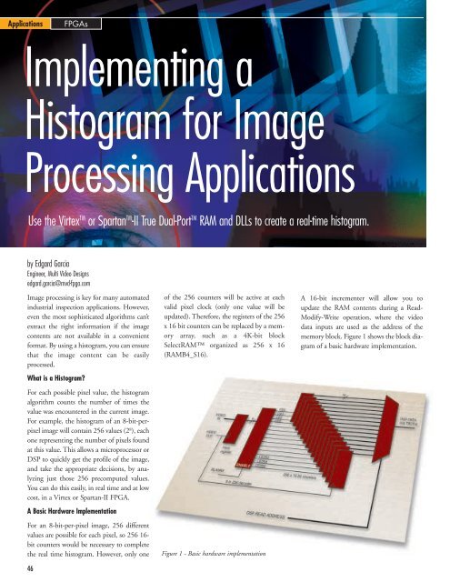
Figure 1 - Basic hardware implementation<br />
A 16-bit incrementer will allow you to<br />
update the RAM contents during a Read-<br />
Modify-Write operation, where the video<br />
data inputs are used as the address of the<br />
memory block. Figure 1 shows the block diagram<br />
of a basic hardware implementation.
<strong>Applications</strong><br />
FPGAs<br />
Optimized Implementation<br />
Each memory cycle can be either a Read<br />
or a Write, so we need to divide each pixel<br />
clock cycle in two sub-cycles: a Read cycle<br />
<strong>for</strong> getting the current value, and a Write<br />
cycle <strong>for</strong> updating (+1) the memory content.<br />
You can do this easily, using a<br />
CLKDLL to recover a clock at twice the<br />
frequency of the video clock (CLK2X),<br />
and to create an image of this clock shifted<br />
by 90° to validate Read and Write<br />
cycles. Figure 2 shows the detailed diagram<br />
of an optimized implementation.<br />
During horizontal and vertical retrace,<br />
pixel values must be discarded. This is<br />
done with no additional logic, by connecting<br />
the BLANKING# signal to the<br />
ENA input of the memory block. Figure<br />
3 illustrates the timing of the operations.<br />
The DSP or microprocessor can directly<br />
read the result of the histogram by using<br />
the B port of the same block SelectRAM<br />
(configured as a RAMB4_S16_S16). A<br />
multiplexer is not needed because the two<br />
ports (A and B) each have dedicated inputs.<br />
Resources and Per<strong>for</strong>mance<br />
Here are the logic resources required <strong>for</strong><br />
implementing the histogram algorithm:<br />
• 1 x CLKDLL + BUFG<br />
• 1 x RAMB4_S16_S16<br />
• 1 x 16-bit INCREMENTER (8 slices)<br />
For a Virtex -6 or Spartan-II -6 device, Fpix<br />
= 50 MHz.<br />
Figure 2 - An optimized implementation<br />
Conclusion<br />
By taking advantage of the high level features<br />
of the Virtex and Spartan-II FPGA<br />
architectures, you can greatly increase the<br />
speed and reduce the cost of your designs.<br />
For more in<strong>for</strong>mation about how to implement<br />
the histogram algorithm, e-mail:<br />
edgard.garcia@mvd-fpga.com<br />
VIDEO_CLOCK<br />
CLK2X<br />
CLK90<br />
BLANKING#<br />
VIDEO_IN<br />
(after register)<br />
10<br />
42 33 10 73 D(n-2) D(n-1)<br />
DOA<br />
0<br />
0 0 1 0 x y<br />
DIA<br />
1 1 1 2 1 x+1 y+1<br />
READ READ READ READ READ READ READ READ READ READ<br />
WRITE WRITE WRITE WRITE WRITE WRITE WRITE WRITE WRITE<br />
PIXEL CYCLE<br />
Figure 3 - Timing<br />
47