Process Control System
Process Control System
Process Control System

Create successful ePaper yourself
Turn your PDF publications into a flip-book with our unique Google optimized e-Paper software.
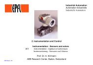
<strong>Control</strong> elements<br />
B5 – 1<br />
B.5 – <strong>Control</strong> elements<br />
All the components for the operation of the stations have been<br />
incorporated in the control console.<br />
Fig. 5.1:<br />
<strong>Control</strong> console<br />
• Function of switches:<br />
− S1 ON / OFF: Operating voltage On / Off<br />
− S2 PUMP: <strong>Control</strong>ler correcting variable acts<br />
on pump / pump runs constantly<br />
− S3 VALVE: Proportional valve closed /<br />
<strong>Control</strong>ler correcting variable acts on<br />
proportional valve<br />
− S4 EXTERNAL<br />
FUNCTION: Freely configurable<br />
• Function of indicator lights:<br />
− H1 CONTROLLER<br />
ON:<br />
Operating voltage On<br />
− H2 ALARM: Alarm<br />
• Allocation of test sockets:<br />
− Individual process signals to be evaluated via external measuring<br />
devices or recording instruments can be connected to the test<br />
sockets.<br />
Standard configuration<br />
• I: X signal flow-rate sensor (0 ... 1 kHz)<br />
• II: Y signal manipulated variable (0 ... 10 V)<br />
• III: ext. SP to connect an external setpoint device<br />
(e.g. 0 ... 10 V; switch controller<br />
to '<strong>Control</strong>ler structure/extern SP'<br />
[refer to operating instructions<br />
of the controller])<br />
Festo Didactic • <strong>Process</strong> <strong>Control</strong> <strong>System</strong>