Process Control System
Process Control System
Process Control System

Create successful ePaper yourself
Turn your PDF publications into a flip-book with our unique Google optimized e-Paper software.
Lernsystem Automatisierung und Kommunikation<br />
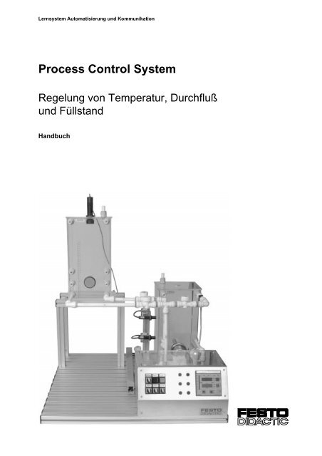
<strong>Process</strong> <strong>Control</strong> <strong>System</strong><br />
Regelung von Temperatur, Durchfluß<br />
und Füllstand<br />
Handbuch
Bestimmungsgemäße Verwendung<br />
Diese Anlage ist ausschließlich für die Aus- und Weiterbildung im<br />
Bereich Automatisierung und Kommunikation entwickelt und hergestellt.<br />
Das Ausbildungsunternehmen und / oder die Ausbildenden hat / haben<br />
dafür Sorge zu tragen, daß von den Auszubildenden die Sicherheitsvorkehrungen,<br />
die in den begleitenden Handbüchern beschrieben sind,<br />
beachtet werden.<br />
Festo Didactic schließt hiermit jegliche Haftung für Schäden des<br />
Auszubildenden, des Ausbildungsunternehmens und / oder sonstiger<br />
Dritter aus, die bei Gebrauch / Einsatz der Anlage außerhalb einer<br />
reinen Ausbildungssituation auftreten; es sei denn Festo Didactic hat<br />
solche Schäden vorsätzlich oder grob fahrlässig verursacht.<br />
Bestell-Nr.: 372 751<br />
Benennung: TECH. DOK.<br />
Bezeichnung: D.VT-TD-TFL-1-D/GB<br />
Stand: 02/1997<br />
Redaktion: Frank Ebel<br />
© Copyright by Festo Didactic KG, D-73734 Esslingen, 1997<br />
Diese Unterlage und alle in ihr enthaltenen Beiträge und Abbildungen<br />
unterliegen dem urheberrechtlichen Schutz. Jede Verwertung außerhalb<br />
der Grenzen des Urheberrechtsgesetzes und außerhalb des Unterrichts<br />
ist ohne unsere Zustimmung unzulässig. Das gilt insbesondere für<br />
Vervielfältigungen, Bearbeitungen, Übersetzungen, Mikroverfilmungen<br />
und die Einspeicherung und Verarbeitung in elektronischen <strong>System</strong>en.<br />
Teile dieser Unterlage dürfen vom berechtigten Verwender<br />
ausschließlich für Unterrichtszwecke vervielfältigt werden.
Inhaltsverzeichnis<br />
A – III<br />
Inhaltsverzeichnis<br />
A.1 Einleitung..................................................................... A1-1<br />
A.2 Arbeits- und Sicherheitshinweise .............................. A2-1<br />
A.3 Übersicht...................................................................... A3-1<br />
A.4 Mechanischer Aufbau ................................................. A4-1<br />
A.4.1 Verrohrung .................................................................... A4-2<br />
A.4.2 Erweitern von Stationen ................................................. A4-3<br />
A.4.3 Kombinieren von Stationen............................................. A4-6<br />
A.5 Bedienelemente........................................................... A5-1<br />
A.6 Beschreibung der Regelstrecken............................... A6-1<br />
A.6.1 Vernetzte Anlage mit 3 Stationen .................................. A6-1<br />
A.6.2 Durchflußregelung......................................................... A6-2<br />
A.6.3 Temperaturregelung...................................................... A6-3<br />
A.6.4 Füllstandsregelung ........................................................ A6-4<br />
A.6.5 Kompaktanlage .............................................................. A6-5<br />
A.7 Inbetriebnahme............................................................ A7-1<br />
A.7.1 Inbetriebnahme von Einzelstationen.............................. A7-1<br />
A.7.2 Inbetriebnahme der Gesamtanlage ............................... A7-2<br />
A.7.3 Reglereinstellungen....................................................... A7-4<br />
A.8 Vernetzung mit Profibus ............................................. A8-1<br />
A.9 Normen und Richtlinien .............................................. A9-1<br />
A.10 Rohrleitungs- und Instrumenten-Fließbilder ........... A10-1<br />
A.10.1 RI-Fließbild Station Durchflußregelung........................ A10-1<br />
A.10.2 RI-Fließbild Station Temperaturregelung..................... A10-2<br />
A.10.3 RI-Fließbild Station Füllstandsregelung ....................... A10-3<br />
A.10.4 RI-Fließbild Kompaktanlage ........................................ A10-4<br />
A.10.5 RI-Fließbild Gesamtanlage .......................................... A10-5<br />
Festo Didactic • <strong>Process</strong> <strong>Control</strong> <strong>System</strong>
A – IV<br />
Inhaltsverzeichnis<br />
A.11 Elektro-Mess-Steuer- und Regel-Stellenpläne......... A11-1<br />
A.11.1 EMSR Stellenplän grob, Station Durchflußregelung .... A11-1<br />
A.11.2 EMSR Stellenplän grob, Station Temperaturregelung . A11-2<br />
A.11.3 EMSR Stellenplän grob, Station Füllstandsregelung.... A11-3<br />
A.12 Stücklisten ................................................................. A12-1<br />
A.12.1 Stückliste Station Durchflußregelung ........................... A12-1<br />
A.12.2 Stückliste Station Temperaturregelung ........................ A12-2<br />
A.12.3 Stückliste Station Füllstandsregelung .......................... A12-3<br />
A.12.4 Stückliste Kompaktanlage............................................ A12-4<br />
A.12.5 Optionale Basiseinheiten und Module.......................... A12-6<br />
A.13 Datenblätter................................................................ A13-1<br />
<strong>Process</strong> <strong>Control</strong> <strong>System</strong> • Festo Didactic
Einleitung<br />
A1 – 1<br />
A.1 – Einleitung<br />
Praxisnahe Ausbildung ist die beste Vorbereitung auf den Beruf. Direkt<br />
an Produktionsanlagen auszubilden ist in den meisten Fällen nicht<br />
möglich. Zum einen wäre das Risiko einer anschließend fehlerhaft<br />
laufenden Anlage zu groß, zum anderen würde der Produktionsablauf<br />
erheblich gestört werden.<br />
Ein praxisnahes Ausbildungssystem wie das <strong>Process</strong> <strong>Control</strong> <strong>System</strong> ist<br />
eine optimale Alternative. An ihr können Auszubildende und<br />
Facharbeiter ohne Zeitdruck auf die Anforderungen im Beruf vorbereitet<br />
werden.<br />
In der Praxis soll ein Team Produktionsanlagen montieren, in Betrieb<br />
nehmen, bedienen, warten und Fehler in Anlagen lokalisieren und<br />
beseitigen.<br />
Für jedes Teammitglied bedeutet dies, daß außer der fachlichen<br />
Kompetenz zusätzliche Qualifikationen für die Teamarbeit trainiert<br />
werden, um ein effektiveres Arbeiten im Team zu ermöglichen. Die<br />
einzelnen Qualifikationen sind:<br />
• Teamfähigkeit,<br />
• Kooperationsbereitschaft,<br />
• Lernfähigkeit,<br />
• Selbständigkeit und<br />
• Organisationsvermögen.<br />
Diese Fähigkeiten und die fachliche Kompetenz werden als berufliche<br />
Handlungskompetenz bezeichnet und sind für den Mitarbeiter der<br />
Schlüssel zur beruflichen Zukunft. Für die technische Aus- und<br />
Weiterbildung in der Verfahrenstechnik bedeutet dies, neue Methoden<br />
zur Vermittlung dieser Qualifizierungsziele anzuwenden. Die Stationen<br />
und Anlagen des <strong>Process</strong> <strong>Control</strong> <strong>System</strong>s sind auf diese<br />
Qualifizierungsziele zugeschnitten.<br />
Festo Didactic • <strong>Process</strong> <strong>Control</strong> <strong>System</strong>
A1 – 2<br />
Einleitung<br />
<strong>Process</strong> <strong>Control</strong> <strong>System</strong> • Festo Didactic
Arbeits- und Sicherheitshinweise<br />
A2 – 1<br />
A.2 – Arbeits- und Sicherheitshinweise<br />
Folgende Hinweise sollten Sie im Interesse Ihrer eigenen Sicherheit<br />
beachten:<br />
Sicherheitshinweise<br />
Allgemein:<br />
r Die Auszubildenden dürfen nur unter Aufsicht einer Ausbilderin /<br />
eines Ausbilders an der Station arbeiten.<br />
r Beachten Sie die Angaben der Datenblätter zu den einzelnen<br />
Elementen, insbesondere auch alle Hinweise zur Sicherheit!<br />
Elektrik:<br />
r<br />
r<br />
Herstellen bzw. Abbauen von elektrischen Verbindungen nur in<br />
spannungslosem Zustand!<br />
Die Heizung wird mit 230 VAC betrieben. Beachten Sie die hierfür<br />
geltenden Sicherheitsbestimmungen bei der Inbetriebnahme!<br />
(DIN VDE 0113 [EN 60204])<br />
Mechanik:<br />
r<br />
r<br />
r<br />
Montieren Sie alle Elemente fest auf die Platte.<br />
Die maximale Betriebstemperatur der Behälter von +65 °C darf<br />
nicht überschritten werden.<br />
Nehmen Sie die Heizung nur in Betrieb, wenn der Heizstab völlig<br />
in die Flüssigkeit getaucht ist.<br />
Festo Didactic • <strong>Process</strong> <strong>Control</strong> <strong>System</strong>
A2 – 2<br />
Arbeits- und Sicherheitshinweise<br />
Arbeitshinweise<br />
r<br />
r<br />
Überprüfen Sie vor Inbetriebnahme der Anlage alle elektrischen<br />
Anschlüsse und alle Rohrleitungen.<br />
Füllen Sie keine verschmutzten Flüssigkeiten in die Behälter ein.<br />
Das Proportionalventil kann sonst verstopfen und die<br />
Pumpendichtungen können beschädigt werden.<br />
<strong>Process</strong> <strong>Control</strong> <strong>System</strong> • Festo Didactic
Übersicht<br />
A3 – 1<br />
A.3 – Übersicht<br />
Das <strong>Process</strong> <strong>Control</strong> <strong>System</strong> kann in der Erstausbildung, Weiterbildung<br />
und Umschulung eingesetzt werden. Das Konzept des <strong>Process</strong> <strong>Control</strong><br />
<strong>System</strong>s ist auf die Berufsbilder Prozeßleitelektroniker, Verfahrenstechniker,<br />
Ver- und Entsorger, Fachkraft für Lebensmitteltechnik, Molkereifachkraft,<br />
Brauer u.ä. zugeschnitten.<br />
Mit den Stationen und Anlagen des <strong>Process</strong> <strong>Control</strong> <strong>System</strong>s ist es<br />
möglich, die Prozesse Füllstands-, Temperatur- und Durchflußregelung<br />
zu untersuchen. Die Anlage besteht aus einzelnen Modulen, die unterschiedlich<br />
kombinierbar sind.<br />
Verschiedenen Ausbaustufen werden ermöglicht. Die Stationen und<br />
Anlagen können selbständig auf- und umgebaut, verrohrt und in Betrieb<br />
genommen werden. Sie sind somit offen für eigene Ideen, eigene Lösungsansätze<br />
und Projektarbeiten.<br />
Es werden ausschließlich industrieübliche Komponenten verwendet, um<br />
eine realitätsgetreue Ausbildung zu gewährleisten. Dieses Ausbildungskonzept<br />
ist die ideale Lösung für den verfahrenstechnischen Unterricht<br />
im Vergleich zu rein simulierten <strong>System</strong>en und großen, raumgebundenen<br />
Industrieanlagen.<br />
Folgende Lerninhalte können mit dem <strong>Process</strong> <strong>Control</strong> <strong>System</strong> vermittelt<br />
werden:<br />
• Messen nicht-elektrischer, verfahrenstechnischer sowie regelungstechnischer<br />
Größen<br />
• Erweiterung von Meßketten zu geschlossenen Regelkreisen<br />
• Aufbau, Inbetriebnahme, Änderung und Wartung von Regelkreisen<br />
• Aufbau, Verschaltung und Inbetriebnahme von Anlagen<br />
• Erweiterung, Änderung, Inbetriebnahme, Inspektion, Wartung und<br />
Instandhaltung von Prozeßleiteinrichtungen sowie Fehlerdiagnose im<br />
Störfall<br />
Festo Didactic • <strong>Process</strong> <strong>Control</strong> <strong>System</strong>
A3 – 2<br />
Übersicht<br />
Das Konzept des <strong>Process</strong> <strong>Control</strong> <strong>System</strong>s basiert auf den folgenden<br />
Punkten:<br />
• Modulares Baukastensystem, stufenweise Erweiterung ist möglich<br />
• Praxisnähe durch den Einsatz von Industriekomponenten<br />
• Leicht zu transportierendes <strong>System</strong><br />
• Betriebsmedium Wasser erlaubt gefahrloses selbständiges Arbeiten<br />
• Offen für neue Technologien wie Prozeßvisualisierung und Prozeßleittechnik<br />
über Profibus<br />
Die Grundkomponenten des <strong>Process</strong> <strong>Control</strong> <strong>System</strong>s sind:<br />
• Behälter<br />
• Pumpen<br />
• Gesteuerte Ventile<br />
• Manuell betätigte Ventile<br />
• Heizung<br />
• Kunststoff-Steckverrohrung<br />
• Sensorik:<br />
r Durchflußsensoren<br />
r Füllstandssensoren<br />
r Temperatursensoren<br />
• Industrieregler<br />
• Elektrische Bauelemente<br />
• Mechanische Bauelemente<br />
<strong>Process</strong> <strong>Control</strong> <strong>System</strong> • Festo Didactic
Übersicht<br />
A3 – 3<br />
Konfigurationsbeispiele der Stationen und Anlagen des<br />
<strong>Process</strong> <strong>Control</strong> <strong>System</strong>s:<br />
• Füllstandsregelung mit Industrieregler<br />
• Temperaturregelung mit Industrieregler<br />
• Durchflußregelung mit Industrieregler<br />
• Durchfluß-, Füllstands- und Temperaturregelung mit Industrieregler<br />
Aufbaubeispiel:<br />
Füllstandsregelung mit Industrieregler<br />
Bild 3.1:<br />
Station Füllstandsregelung<br />
Eingesetzte Komponenten:<br />
1 Pumpe 2 Behälter<br />
1 Motorregeler 1 Bedienpult<br />
1 Analoger Ultraschallsensor 1 Profilplatte<br />
1 Digitaler Industrieregler Verrohrung<br />
elektrische und mechanische<br />
Bauelemente<br />
optional:<br />
Kapazitive Näherungsschalter<br />
Festo Didactic • <strong>Process</strong> <strong>Control</strong> <strong>System</strong>
A3 – 4<br />
Übersicht<br />
Aufbaubeispiel:<br />
Temperaturregelung mit Industrieregler<br />
Bild 3.2:<br />
Station Temperaturregelung<br />
Eingesetzte Komponenten:<br />
1 Pumpe 1 Behälter<br />
1 Heizung 1 Bedienpult<br />
1 Temperatursensor 1 Profilplatte<br />
1 Digitaler Industrieregler Verrohrung<br />
elektrische und mechanische<br />
Bauelemente<br />
optional:<br />
Kapazitive Näherungsschalter<br />
<strong>Process</strong> <strong>Control</strong> <strong>System</strong> • Festo Didactic
Übersicht<br />
A3 – 5<br />
Aufbaubeispiel:<br />
Durchflußregelung mit Industrieregler<br />
Bild 3.3:<br />
Station Durchflußregelung<br />
Eingesetzte Komponenten:<br />
1 Pumpe 1 Behälter<br />
1 Motorregeler 1 Bedienpult<br />
1 Proportionalventil 1 Profilplatte<br />
1 Durchflußsensor Verrohrung<br />
1 Digitaler Industrieregler elektrische und mechanische<br />
Bauelemente<br />
optional:<br />
Kapazitive Näherungsschalter<br />
Festo Didactic • <strong>Process</strong> <strong>Control</strong> <strong>System</strong>
A3 – 6<br />
Übersicht<br />
Aufbaubeispiel:<br />
Durchfluß-, Füllstands- und Temperaturregelung mit Industrieregler<br />
(Kompaktanlage)<br />
Bild 3.4:<br />
Kompaktanlage<br />
Eingesetzte Komponenten:<br />
1 Pumpe 2 Behälter<br />
1 Motorregeler 1 Bedienpult<br />
1 Heizung 1 Profilplatte<br />
1 Durchflußsensor Verrohrung<br />
1 Temperatursensor elektrische und mechanische<br />
1 Analoger Ultraschallsensor Bauelemente<br />
1 Digitaler Industrieregler<br />
optional:<br />
Kapazitive Näherungsschalter<br />
<strong>Process</strong> <strong>Control</strong> <strong>System</strong> • Festo Didactic
Übersicht<br />
A3 – 7<br />
Alle Konfigurationen mit dem digitalen Industrieregler können mit einer<br />
Visualisierungs-Software ausgestattet werden.<br />
Bild 3.5:<br />
Visualisierungs-Software –<br />
Startbildschirm<br />
Bild 3.6:<br />
Visualisierungs-Software –:<br />
Informationen zum<br />
Pt 100 Sensor<br />
Festo Didactic • <strong>Process</strong> <strong>Control</strong> <strong>System</strong>
A3 – 8<br />
Übersicht<br />
Bild 3.7:<br />
Visualisierungs-Software –<br />
Parametereinstellung<br />
und Meßwerterfassung<br />
Kundenspezifische Konfigurationen mit SPS sind möglich.<br />
<strong>Process</strong> <strong>Control</strong> <strong>System</strong> • Festo Didactic
Mechanischer Aufbau<br />
A4 – 1<br />
A.4 – Mechanischer Aufbau<br />
Die Stationen des <strong>System</strong>s sind auf Profilplatten (700 mm x 700 mm)<br />
aufgebaut. Durch dieses Maß ergibt sich eine gute Kombinierbarkeit der<br />
einzelnen Stationen.<br />
Bild 4.1:<br />
Mechanischer Aufbau<br />
Folgende Stationen sind verfügbar:<br />
• Station TEMPERATURREGELUNG:<br />
− Regelstrecke mit Ausgleich<br />
− langsame Regelstrecke<br />
• Station DURCHFLUSSREGELUNG:<br />
− Regelstrecke mit Ausgleich<br />
− schnelle Regelstrecke<br />
• Station FÜLLSTANDSREGELUNG:<br />
− I-Regelstrecke<br />
Festo Didactic • <strong>Process</strong> <strong>Control</strong> <strong>System</strong>
A4 – 2<br />
Mechanischer Aufbau<br />
A.4.1 – Verrohrung<br />
Die Verrohrung besteht aus einem Rohr- und Steckverbindersystem aus<br />
Kunststoff. Die Verrohrung der verfahrenstechnischen Anlagen erfolgt<br />
schnell, sicher und dicht.<br />
Bild 4.2:<br />
Komponenten<br />
der Verrohrung,<br />
Rohrschneider<br />
Montage / Demontage<br />
• Zum Ablängen der Rohre wird ein Rohrschneider benötigt<br />
• Die Rohrmontage / -demontage erfolgt ohne Werkzeuge.<br />
r Montage:<br />
Das Rohr wird bis zum Anschlag in den Steckverbinder geschoben<br />
r Demontage:<br />
Zum Lösen der Verbindung wird die Klemmhülse am Steckverbinder<br />
eingedrückt und das Rohr herausgezogen.<br />
<strong>Process</strong> <strong>Control</strong> <strong>System</strong> • Festo Didactic
Mechanischer Aufbau<br />
A4 – 3<br />
A.4.2 – Erweitern von Stationen<br />
Durch den modularen Aufbau können alle Stationen einfach erweitert<br />
werden.<br />
• Integration zusätzlicher Regelstrecken:<br />
+ +<br />
Station<br />
Füllstandsregelung<br />
+ Basiseinheit<br />
Durchflußsensor<br />
+ Basiseinheit<br />
Proportionalventil<br />
Sie erhalten die Regelstrecken Füllstand und Durchfluß.<br />
Festo Didactic • <strong>Process</strong> <strong>Control</strong> <strong>System</strong>
A4 – 4<br />
Mechanischer Aufbau<br />
• Ersetzen von Handventilen durch Magnetventile:<br />
+<br />
Station<br />
Füllstandsregelung<br />
+ Basiseinheit<br />
Magnetventil<br />
LI<br />
30<br />
LIC<br />
30<br />
V el.<br />
V ab<br />
P<br />
a<br />
Sie erhalten eine elektrisch zuschaltbare Störgröße (z.B. Öffnen eines<br />
Bypasses).<br />
<strong>Process</strong> <strong>Control</strong> <strong>System</strong> • Festo Didactic
Mechanischer Aufbau<br />
A4 – 5<br />
• Füllstandsüberwachung<br />
Mit Hilfe von kapazitiven Näherungsschaltern läßt sich eine Füllstandsüberwachung<br />
realisieren.<br />
Mit einem Haltewinkel werden die Näherungsschalter an einem Profilstab<br />
befestigt. Die Näherungsschalter können stufenlos in der Höhe<br />
verschoben werden.<br />
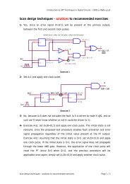
Das Ausgangssignal wird über den Binäreingang an den Regler geleitet.<br />
0 V 24 V Out Alarm Out B1 Pt100 IN Bin<br />
+<br />
S<br />
-<br />
1<br />
2<br />
3<br />
+<br />
-<br />
1<br />
2<br />
-<br />
+<br />
+<br />
+<br />
+<br />
-<br />
-<br />
-<br />
-<br />
Analog Terminal<br />
BN<br />
BK<br />
BU<br />
BU<br />
BK<br />
BN<br />
BK<br />
BU<br />
H2<br />
B<br />
Pt100<br />
230V/115V<br />
PE<br />
L1<br />
N<br />
H1<br />
S2<br />
S1<br />
M<br />
P<br />
24VDC<br />
0VDC<br />
Durch Konfiguration des Reglers im Menü 'Zusätze', 'Bin Ein' kann<br />
ein Alarm bei<br />
− unterschreiten eines Füllstandes (Wirksinn 'Inv: Ja')<br />
oder<br />
− überschreiten eines Füllstandes (Wirksinn 'Inv = Nein')<br />
ausgelöst werden.<br />
Festo Didactic • <strong>Process</strong> <strong>Control</strong> <strong>System</strong>
A4 – 6<br />
Mechanischer Aufbau<br />
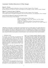
A.4.3 – Kombinieren von Stationen<br />
Einzelne Stationen können mit Profilverbinden verbunden werden.<br />
Mit einer zusätzlichen Pumpe und zwei Ventilen pro Station können Stationen<br />
zur Weiterleitung der Flüssigkeit miteinander verbunden werden.<br />
Bild 4.3:<br />
Kombination von<br />
Stationen zu Anlagen<br />
V3<br />
V1<br />
V4<br />
V2<br />
V4<br />
V2<br />
P<br />
V3<br />
V1<br />
P<br />
Die Ventile können als Handventile, Magnetventile oder als Kombination<br />
der beiden Ventiltypen ausgeführt sein.<br />
Die Ansteuerung kann somit von Hand, über eine Relaissteuerung oder<br />
über eine Speicherprogrammierbare Steuerung erfolgen.<br />
<strong>Process</strong> <strong>Control</strong> <strong>System</strong> • Festo Didactic
Bedienelemente<br />
A5 – 1<br />
A.5 – Bedienelemente<br />
In einem Bedienpult sind alle Komponenten zur Bedienung der<br />
Stationen zusammengefaßt.<br />
Bild 5.1:<br />
Bedienpult<br />
• Funktion der Schalter:<br />
− S1 EIN / AUS: Betriebsspannung Ein / Aus<br />
− S2 PUMPE: Reglerstellgröße wirkt auf Pumpe /<br />
Pumpe läuft konstant<br />
− S3 VENTIL: Proportionalventil geschlossen /<br />
Reglerstellgröße wirkt auf<br />
Proportionalventil<br />
− S4 EXTERNE<br />
FUNKTION: Frei konfigurierbar<br />
• Funktion der Leuchtmelder:<br />
− H1 STEUERUNG<br />
EIN:<br />
Betriebsspannung Ein<br />
− H2 ALARM: Alarm<br />
• Belegung der Meßbuchsen:<br />
− An die Meßbuchsen können individuell Prozeßsignale gelegt<br />
werden, die mit externen Meßgeräten oder Schreibern<br />
ausgewertet werden sollen.<br />
Standard-Belegung<br />
• I: X-Meßsignal Durchflußsensor (0 ... 1 kHz)<br />
• II: Y-Meßsignal Stellgröße (0 ... 10 V)<br />
• III: ext. SP Anschlußmöglichkeit für externen<br />
Sollwertgeber (z.B. 0 ... 10 V; Regler muß<br />
auf 'Struktur/extern W' geschaltet sein<br />
[siehe Reglerhandbuch])<br />
Festo Didactic • <strong>Process</strong> <strong>Control</strong> <strong>System</strong>
A5 – 2<br />
Bedienelemente<br />
• Analog-Terminal<br />
Über das Analog-Terminal werden Sensoren, Aktoren und<br />
Bedienelemente an den eingesetzten Industrieregler angeschlossen.<br />
− Eingänge<br />
Pt 100<br />
Level (0 ... 20 mA)<br />
Flow (0 ... 1 kHz)<br />
S. Funct. (0 ... 1 kHz)<br />
ext. Sp. (0 ... 10 V)<br />
In Bin (0 / 24 V)<br />
Reglereingang 1 'Istwert'<br />
Die Umstellung zwischen:<br />
• Pt 100,<br />
• Level und<br />
• Flow<br />
erfolgt am Regler in den entsprechenden<br />
Konfigurationsmenüs oder mit der<br />
Visualisierungs-Software<br />
Reglereingang 2<br />
am Regler konfigurierbar für :<br />
• Störgrößenaufschaltung<br />
• Kaskadenregelung<br />
• Folgeregelung<br />
• Verhältnisregelung oder<br />
• externer Sollwert<br />
Binäreingang<br />
am Regler konfigurierbar für:<br />
• Auslösen von Alarm<br />
• Umschalten Hand / Automatik<br />
• Umschalten externer / interner Sollwert<br />
− Ausgänge<br />
Out U (0 ... 10 V)<br />
Out I (0 ... 20 mA)<br />
Out B1 (0 / 24 V)<br />
Out B2 (0 / 24 V)<br />
Out B3 (0 / 24 V)<br />
Out Alarm (0 / 24 V; 24 / 0 V)<br />
Reglerausgang 'Stellgröße'<br />
am Regler konfigurierbar als:<br />
• stetiger Ausgang (0 ... 10 V, 0 ... 20 mA)<br />
• 2-Punkt pulsweitenmodulierter Ausgang (B1)<br />
• 3-Punkt pulsweitenmodulierter Ausgang<br />
(B1, B2)<br />
Binärausgang<br />
am Regler konfigurierbar für:<br />
• Meldung Alarm<br />
• Meldung Fehler<br />
• Meldung Hand<br />
Ausgang für Alarmmeldung<br />
(invertiert oder nicht invertiert)<br />
<strong>Process</strong> <strong>Control</strong> <strong>System</strong> • Festo Didactic
Beschreibung der Regelstrecken<br />
A6 – 1<br />
A.6 – Beschreibung der Regelstrecken<br />
A6.1 – Vernetzte Anlage mit 3 Stationen<br />
Mit der vernetzten Anlage ist es möglich, die Prozesse Füllstands-,<br />
Temperatur- und Durchflußregelung zu untersuchen.<br />
LI<br />
30<br />
LIC<br />
30<br />
FIC<br />
20<br />
TIC<br />
10<br />
V ab<br />
a<br />
P<br />
V ab<br />
HSO<br />
FI<br />
LIA -<br />
20<br />
20<br />
TI LS<br />
10 10 10<br />
V ab<br />
P<br />
a<br />
P<br />
Bild 6.1:<br />
Fließbild der vernetzten Anlage<br />
Die Behälter sind durch Rohre verbunden. Mit den Pumpen P wird die<br />
Flüssigkeit umgepumpt.<br />
Die Absperrhähne bzw. Magnetventile sind zum Einstellen der<br />
verschiedenen Prozeßarten und zur Störungsaufschaltung zu<br />
verwenden.<br />
Als universelle Regler für die Prozesse Füllstands-, Temperatur- und<br />
Durchflußregelung werden digitale Industrieregler eingesetzt.<br />
Festo Didactic • <strong>Process</strong> <strong>Control</strong> <strong>System</strong>
A6 – 2<br />
Beschreibung der Regelstrecken<br />
A.6.2 – Durchflußregelung<br />
An der aufgebauten Durchflußregelstrecke kommen zwei Betriebsarten<br />
zum Einsatz:<br />
• Durchflußregelung mit Hilfe eines Proportionalventils.<br />
Die Stellgröße ist hier der Hub des Ventilkolbens, die Pumpe P läuft<br />
konstant.<br />
• Durchflußregelung mit Hilfe der Pumpe.<br />
Stellgröße ist hier die Drehzahl der Pumpe.<br />
Das Umstellen zwischen den beiden Betriebsarten ist durch<br />
handbetätigte Absperrhähne einfach möglich.<br />
Bild 6.2:<br />
Fließbild Durchflußregelung<br />
FIC<br />
20<br />
HSO<br />
20<br />
V ab<br />
P<br />
FI<br />
20<br />
a<br />
<strong>Process</strong> <strong>Control</strong> <strong>System</strong> • Festo Didactic
Beschreibung der Regelstrecken<br />
A6 – 3<br />
A.6.3 – Temperaturregelung<br />
An der aufgebauten Temperaturregelstrecke kann die Temperatur einer<br />
Flüssigkeit mit einer Heizung erhöht werden. Um eine ständige<br />
Durchmischung der Flüssigkeit zu gewährleisten, wird die Flüssigkeit mit<br />
der Pumpe P ständig umgewälzt.<br />
Beachten Sie die maximale Betriebstemperatur der Behälter<br />
von +65 °C<br />
Nehmen Sie die Heizung nur in Betrieb, wenn der Heizstab völlig in die<br />
Flüssigkeit getaucht ist.<br />
Bild 6.3:<br />
TIC<br />
Fließbild<br />
10<br />
Temperaturregelung<br />
LIA -<br />
10<br />
TI<br />
10<br />
LS<br />
10<br />
P<br />
Festo Didactic • <strong>Process</strong> <strong>Control</strong> <strong>System</strong>
A6 – 4<br />
Beschreibung der Regelstrecken<br />
A.6.4 – Füllstandsregelung<br />
An der aufgebauten Füllstandsregelstrecke kann die Füllhöhe der<br />
Flüssigkeit in einem Behälter geregelt werden.<br />
• Der Füllstand der Flüssigkeit wird mit einem analogen<br />
Ultraschallsensor ermittelt.<br />
• Zur Störung der Regelstrecke kann die Flüssigkeit durch teilweises<br />
oder vollständiges Öffnen des Absperrhahns in den unteren Behälter<br />
abgelassen werden.<br />
Bild 6.4:<br />
Füllstandsregelung<br />
LI<br />
30<br />
LIC<br />
30<br />
V ab<br />
P<br />
a<br />
<strong>Process</strong> <strong>Control</strong> <strong>System</strong> • Festo Didactic
Beschreibung der Regelstrecken<br />
A6 – 5<br />
A.6.5 – Kompaktanlage<br />
Bei der Kompaktanlage sind die Regelstrecken Durchfluß, Temperatur<br />
und Füllstand durch entsprechende Umschaltung der Ventile bzw.<br />
Konfiguration des Reglers möglich.<br />
LI<br />
30<br />
Bild 6.5:<br />
Fließbild Kompaktanlage<br />
TI<br />
10<br />
LIA -<br />
10<br />
FIC<br />
20<br />
HSO<br />
20<br />
V ab<br />
P<br />
FI<br />
20<br />
a<br />
Festo Didactic • <strong>Process</strong> <strong>Control</strong> <strong>System</strong>
A6 – 6<br />
Beschreibung der Regelstrecken<br />
<strong>Process</strong> <strong>Control</strong> <strong>System</strong> • Festo Didactic
Inbetriebnahme<br />
A7 – 1<br />
A.7 – Inbetriebnahme<br />
A.7.1 – Inbetriebnahme von Einzelstationen<br />
r Überprüfen Sie vor Inbetriebnahme der Anlage alle elektrischen<br />
Anschlüsse und alle Rohrleitungen!<br />
r Füllen Sie 10 bis 12 l Wasser in den Behälter ein.<br />
Die Verwendung von destilliertem Wasser sorgt für eine längere<br />
wartungsfreie Betriebsdauer der Anlage.<br />
(Proportionalventil, Pumpen)<br />
r Überprüfen Sie die Dichtigkeit der Leitungsanschlüsse und der<br />
Verrohrung der Anlage.<br />
r Schalten Sie die 24 VDC Steuerspannung ein.<br />
r Zum Entlüften der Pumpe schalten Sie diese eventuell mehrmals ein<br />
und aus.<br />
Festo Didactic • <strong>Process</strong> <strong>Control</strong> <strong>System</strong>
A7 – 2<br />
Inbetriebnahme<br />
A.7.2 – Inbetriebnahme der Gesamtanlage<br />
r Überprüfen Sie vor Inbetriebnahme der Anlage alle elektrischen<br />
Anschlüsse und alle Rohrleitungen!<br />
r Zum Befüllen den Behälter B mit destilliertem Wasser füllen.<br />
In der gesamten Anlage darf nicht mehr Wasser sein, wie dieser eine<br />
Behälter faßt.<br />
r Ventil h a schließen<br />
r Ventil h b schließen<br />
r Ventil h c öffnen<br />
h a<br />
h c<br />
B<br />
h b<br />
P<br />
<strong>Process</strong> <strong>Control</strong> <strong>System</strong>• Festo Didactic
Inbetriebnahme<br />
A7 – 3<br />
r Mit der Pumpe P das Wasser in die anderen Teilstationen pumpen,<br />
damit in jeder Station mindestens soviel Wasser ist, daß der jeweils<br />
untere Füllstandssensor an den jeweiligen Behältern anspricht.<br />
zur Station Durchflußregelung<br />
zur Station Temperaturregelung<br />
zur Station<br />
Füllstandsregelung<br />
h6<br />
h5<br />
h4<br />
h3<br />
h2<br />
h1<br />
Dazu die Handventile h1 bis h6 wie in der Tabelle beschrieben<br />
betätigen:<br />
h1 h2 h3 h4 h5 h6 Station<br />
Temperaturregelung<br />
Füllstand der Behälter<br />
Station<br />
Durchflußregelung<br />
Station<br />
Füllstandsregelung<br />
zu auf zu zu zu auf<br />
b<br />
a<br />
b<br />
a<br />
b<br />
a<br />
auf zu zu zu zu auf<br />
b<br />
a<br />
zu zu zu auf zu auf<br />
b<br />
a<br />
zu zu auf zu zu auf<br />
b<br />
a<br />
r h b öffnen, h6 schließen<br />
h c schließen, Pumpe aus<br />
h a öffnen<br />
r Die Verwendung von destilliertem Wasser sorgt für eine längere<br />
wartungsfreie Betriebsdauer der Anlage.<br />
(Proportionalventil, Pumpen)<br />
r Überprüfen Sie die Dichtigkeit der Leitungsanschlüsse und der<br />
Verrohrung der Anlage.<br />
r Schalten Sie die 24 VDC Steuerspannung ein.<br />
r Zum Entlüften der Pumpen schalten Sie diese eventuell mehrmals<br />
ein und aus.<br />
Festo Didactic • <strong>Process</strong> <strong>Control</strong> <strong>System</strong>
A7 – 4<br />
Inbetriebnahme<br />
A.7.3 – Reglereinstellungen<br />
(Ausführliche Informationen über das Bedienen des Reglers, entnehmen Sie bitte der<br />
Bedienungsanleitung des Reglers, Kapitel 6. Beachten Sie die Hinweise zur Sicherheit<br />
in der Bedienungsanleitung des Reglers.)<br />
Der Industrieregler läßt sich über verschiedene Menüs konfigurieren. In<br />
die Konfigurierebene des Reglers gelangt man durch gleichzeitiges<br />
Drücken der SELECT- und ENTER-Taste (5 sec. lang).<br />
Temperaturregelung<br />
Durchflußregelung<br />
Füllstandsregelung<br />
Struktur standard standard standard<br />
Eingang1 Pt100 3-Draht Frequenz 0-20mA<br />
- Fre: 1000 Rad: aus<br />
Skalierung - X1o 100.0 X1o 100.0<br />
- X1u 0.00 X1u 0.00<br />
Sollwertgrenzen W1o 60.00 W1o 100.0 W1o 100.0<br />
W1u 0.00 W1u 0.00 W1u 0.00<br />
Alarm-Modus Al abs Al abs Al abs<br />
Alarmgrenzen X1+ 60.00 X1+ 100.0 X1+ 100.0<br />
X1- 0.00 X1- 0.00 X1- 0.00<br />
Hy 1.00 Hy 1.00 Hy 1.00<br />
Filter Fg1 20.00 Fg1 20.00 Fg1 20.00<br />
Regler Kp 4.00 Kp 3.50 Kp 28<br />
Tn 2500 Tn 0.40 Tn 5.00<br />
Tv 0.00 Tv 0.00 Tv 0.00<br />
Y0 0.00 Y0 0.00 Y0 0.00<br />
Ausgang 2Pkt-PWM stetig stetig<br />
Signalart 0-10V 0-10V<br />
Periodendauer T+ 10.00<br />
Stellgrößen- Yo 100.0 Yo 100.0 Yo 100.0<br />
begrenzung Yu 0.00 Yu 0.00 Yu 0.00<br />
Wirkungssinn Inv nein Inv nein Inv nein<br />
Impulsausgang Imp nein<br />
Sicherh<br />
Ys 0.00 Ys 0.00 Ys 0.00<br />
Adap.Reg<br />
Tune aus Tune aus Tune aus<br />
Adapt aus Adapt aus Adapt aus<br />
Zusätze<br />
mit Visualisierungs-<br />
Software<br />
Sprache Deutsch Sprache Deutsch Sprache Deutsch<br />
Seriell remote Seriell remote Seriell remote<br />
Profibus Addr 002 Addr 003 Addr 005<br />
RS232 Addr 1 Addr 1 Addr 1<br />
BinEin nicht BinEin nicht BinEin nicht<br />
BinAus nicht BinAus nicht BinAus nicht<br />
Rampe aus Rampe aus Rampe aus<br />
SPT aus SPT aus SPT aus<br />
Zeile2 Istw Zeile2 Istw Zeile2 Istw<br />
Code - Code - Code -<br />
<strong>Process</strong> <strong>Control</strong> <strong>System</strong>• Festo Didactic
Vernetzung mit Profibus<br />
A8 – 1<br />
A.8 – Vernetzung mit Profibus<br />
Die Vernetzung der verfahrenstechnischen Gesamtanlage wird mit dem<br />
Feldbus Profibus realisiert.<br />
Leitrechner /<br />
Prozeßvisualisierung<br />
Bild 8.1:<br />
Vernetzung der<br />
Gesamtanlage mit Profibus<br />
Profibus<br />
Knoten 1 Knoten 2 Knoten 3 Knoten 4<br />
Temperatur Durchfluß Füllstand<br />
SPS Regler Regler Regler<br />
Addr. 4 Addr. 2 Addr. 3 Addr. 5<br />
Prozesse<br />
Mit Hilfe einer Prozeßvisualisierungssoftware werden die benötigten Einund<br />
Ausgangssignale der einzelnen Prozesse der Gesamtanlage<br />
gesteuert.<br />
• Pinbelegung<br />
1 Schirm<br />
3 Data +<br />
5 Datenbezug GND<br />
8 Data –<br />
1<br />
2<br />
3<br />
4<br />
5<br />
6<br />
7<br />
8<br />
9<br />
6<br />
7<br />
8<br />
9<br />
1<br />
2<br />
3<br />
4<br />
5<br />
Der Schirm darf niemals an die Datenbezugsleitung Pin 5<br />
angeschlossen werden.<br />
Festo Didactic • <strong>Process</strong> <strong>Control</strong> <strong>System</strong>
A8 – 2<br />
Vernetzung mit Profibus<br />
• Busabschluß<br />
Beim ersten und letzten Knoten, hier den Knoten 1 und 4, muß ein<br />
Busabschluß vorgenommen werden. Dies läßt sich bei vielen<br />
Profibusteilnehmern über DIP-Schalter einstellen. Der Busabschluß<br />
entspricht der abgebildeten Schaltung.<br />
390 Ohm, 1/4 W150 Ohm, 1/4 W 390 Ohm, 1/4 W<br />
5V<br />
(Pin 6)<br />
Data +<br />
(Pin 3)<br />
Data -<br />
(Pin 8)<br />
GND<br />
(Pin 5)<br />
• Verschaltung<br />
Die einzelnen Komponenten werden wie in der folgenden Tabelle<br />
dargestellt verschaltet.<br />
lfd. Nr. Verbindung von nach<br />
1 Profibus-Einsteckkarte PC Profibus T-Verteiler 1<br />
Teilanlage Temperaturregelung<br />
2 Profibus T-Verteiler 1<br />
Teilanlage Temperaturregelung<br />
a) SPS<br />
b) Profibus T-Verteiler 2<br />
Teilanlage Temperaturregelung<br />
3 Profibus T-Verteiler 2<br />
Teilanlage Temperaturregelung<br />
4 Profibus T-Verteiler<br />
Teilanlage Durchflussregelung<br />
5 Profibus T-Verteiler<br />
Teilanlage Füllstandsregelung<br />
a) Industrieregler<br />
Temperaturregelung<br />
b) Profibus T-Verteiler<br />
Teilanlage Durchflussregelung<br />
a) Industrieregler<br />
Durchflussregelung<br />
b) Profibus T-Verteiler<br />
Teilanlage Füllstandsregelung<br />
a) Industrieregler<br />
Füllstandsregelung<br />
<strong>Process</strong> <strong>Control</strong> <strong>System</strong> • Festo Didactic
Normen und Richtlinien<br />
A9 – 1<br />
A.9 – Normen und Richtlinien<br />
DIN VDE 0100<br />
DIN VDE 0113/<br />
EN 60204<br />
VDI/VDE 2180<br />
VDI 2880<br />
DIN 19 226<br />
DIN 19 227<br />
DIN 19 235<br />
DIN 19 239<br />
DIN 19 240<br />
Bestimmungen für das Errichten von Starkstromanlagen<br />
bei Nennspannungen bis 1000 V<br />
Elektrische Ausrüstung von Industriemaschinen;<br />
Allgemeine Festlegungen<br />
Sicherung von Anlagen der Verfahrenstechnik<br />
mit Mitteln der Meß-, Steuerungs- und<br />
Regelungstechnik;<br />
Blatt 1: Einführung, Begriffe, Erklärungen<br />
Blatt 5: Bauliche und installationstechnische<br />
Maßnahmen zur Funktionssicherung<br />
von Meß-, Steuerungs- und Regeleinrichtungen in<br />
Ausnahmezuständen<br />
Speicherprogrammierbare Steuerungsgeräte;<br />
Blatt 1: Definitionen und Kenndaten<br />
Blatt 2: Prozeß- und Datenschnittstellen<br />
Blatt 3: Programmier- und Testeinrichtungen<br />
Blatt 4: Programmiersprachen<br />
Blatt 5: Sicherheitstechnische Grundsätze<br />
Messen, Steuern, Regeln;<br />
Regelungstechnik und Steuerungstechnik;<br />
Teil 5: Funktionelle und gerätetechnische Begriffe<br />
Messen, Steuern, Regeln;<br />
Grapische Symbole und Kennbuchstaben für die<br />
Prozeßleittechnik<br />
Messen, Steuern, Regeln;<br />
Meldung von Betriebszuständen<br />
Messen, Steuern, Regeln;<br />
Speicherprogrammierte Steuerungen,<br />
Programmierung<br />
Messen, Steuern, Regeln;<br />
Peripherie-Schnittstellen elektronischer Steuerungen;<br />
Stromversorgung und binäre Schnittstellen<br />
Festo Didactic • <strong>Process</strong> <strong>Control</strong> <strong>System</strong>
A9 – 2<br />
Normen und Richtlinien<br />
DIN 28 004<br />
DIN 40 719<br />
DIN 40 900<br />
DIN 45 140<br />
Fließbilder verfahrenstechnischer Anlagen;<br />
Begriffe, Fließbildarten, Informationsinhalt<br />
Schaltungsunterlagen;<br />
Teil 6: Regeln für Funktionspläne,<br />
IEC 848 modifiziert<br />
Teil 60: Ausführung von Funktionsplänen für Messen,<br />
Steuern, Regeln<br />
Graphische Symbole für Schaltunterlagen;<br />
Teil 7: Schaltzeichen für Schalt- und Schutzeinrichtungen<br />
Teil 12: Binäre Elemente<br />
Messen, Steuern, Regeln;<br />
Anschlußkennzeichnung von MSR-Geräten,<br />
Teil 1: Festlegung des alphanumerischen <strong>System</strong>s<br />
Teil 2: Ausführung des Übersetzungsschlüssels<br />
<strong>Process</strong> <strong>Control</strong> <strong>System</strong>• Festo Didactic
Fließbilder<br />
A10 – 1<br />
A.10 – Rohrleitungs- und Instrumenten - Fließbilder<br />
A.10.1 – RI - Fließbild Station Durchflußregelung<br />
FIC<br />
20<br />
HSO<br />
20<br />
V ab<br />
P<br />
FI<br />
20<br />
a<br />
Festo Didactic • <strong>Process</strong> <strong>Control</strong> <strong>System</strong>
A10 – 2<br />
Fließbilder<br />
A.10.2 – RI - Fließbild Station Temperaturregelung<br />
TIC<br />
10<br />
LIA -<br />
TI LS<br />
10 10 10<br />
V ab<br />
P<br />
<strong>Process</strong> <strong>Control</strong> <strong>System</strong>• Festo Didactic
Fließbilder<br />
A10 – 3<br />
A.10.3 – RI - Fließbild Station Füllstandsregelung<br />
LI<br />
30<br />
LIC<br />
30<br />
V ab<br />
P<br />
a<br />
Festo Didactic • <strong>Process</strong> <strong>Control</strong> <strong>System</strong>
A10 – 4<br />
Fließbilder<br />
A.10.4 – RI - Fließbild Kompaktanlage<br />
LI<br />
30<br />
TI<br />
10<br />
LIA -<br />
10<br />
FIC<br />
20<br />
HSO<br />
20<br />
V ab<br />
P<br />
FI<br />
20<br />
a<br />
<strong>Process</strong> <strong>Control</strong> <strong>System</strong>• Festo Didactic
Fließbilder<br />
A10 – 5<br />
A.10.5 – RI - Fließbild Gesamtanlage<br />
LI<br />
30<br />
V ab<br />
a<br />
LIC<br />
30<br />
P<br />
V ab<br />
a<br />
FIC<br />
20<br />
HSO<br />
20<br />
P<br />
FI<br />
20<br />
TIC<br />
10<br />
LIA -<br />
TI LS<br />
10 10 10<br />
V ab<br />
P<br />
Festo Didactic • <strong>Process</strong> <strong>Control</strong> <strong>System</strong>
A10 – 6<br />
Fließbilder<br />
<strong>Process</strong> <strong>Control</strong> <strong>System</strong>• Festo Didactic
EMSR Stellenpläne<br />
A11 – 1<br />
A.11 – Elektro-Mess-Steuer- und Regel-Stellenpläne<br />
A11.1 – EMSR Stellenplan grob, Station Durchflußregelung<br />
Leitwarte<br />
Schaltraum<br />
Feld<br />
Festo Didactic • <strong>Process</strong> <strong>Control</strong> <strong>System</strong>
A11 – 2<br />
EMSR Stellenpläne<br />
A11.2 – EMSR Stellenplan grob, Station Temperaturregelung<br />
Leitwarte<br />
Schaltraum<br />
Feld<br />
<strong>Process</strong> <strong>Control</strong> <strong>System</strong> • Festo Didactic
EMSR Stellenpläne<br />
A11 – 3<br />
A11.3 – EMSR Stellenplan grob, Station Füllstandsregelung<br />
Leitwarte<br />
Schaltraum<br />
Feld<br />
Festo Didactic • <strong>Process</strong> <strong>Control</strong> <strong>System</strong>
A11 – 4<br />
EMSR Stellenpläne<br />
<strong>Process</strong> <strong>Control</strong> <strong>System</strong> • Festo Didactic
Stücklisten<br />
A12 – 1<br />
A.12 – Stücklisten<br />
A.12.1 – Stückliste Station Durchflußregelung<br />
• mit Bürkert-Regler: Best.-Nr. 170 668<br />
Pos. Best.-Nr. Menge Benennung<br />
1 170 711 1 Durchflußsensor<br />
2 170 712 1 Pumpe<br />
3 170 698 1 Motorregler<br />
4 170714 1 Proportionalventil<br />
5 170 716 1 Kugelhahn<br />
6 170 696 1 Regler Bürkert 1110<br />
7 170 699 1 Analog-Terminal<br />
8 170 708 1 Bedienpult<br />
9 170 707 1 Behälter<br />
10 007 658 1 Rohrschneider<br />
11 170 700 5 Rohrstück<br />
12 170 701 6 Winkel-Verbinder<br />
13 170 702 2 T-Verbinder<br />
14 170 703 1 Handventil<br />
15 159 410 1 Profilplatte 700 mm x 700 mm<br />
Festo Didactic • <strong>Process</strong> <strong>Control</strong> <strong>System</strong>
A12 – 2<br />
Stücklisten<br />
A.12.2 – Stückliste Station Temperaturregelung<br />
• mit Bürkert-Regler: Best.-Nr. 170 667<br />
Pos. Best.-Nr. Menge Benennung<br />
1 170 709 1 Temperatursensor<br />
2 170 712 1 Pumpe<br />
3 170 713 1 Heizung<br />
4 170 716 1 Kugelhahn<br />
5 170 696 1 Regler Bürkert 1110<br />
6 170 699 1 Analog-Terminal<br />
7 170 708 1 Bedienpult<br />
8 170 707 1 Behälter<br />
9 007 658 1 Rohrschneider<br />
10 170 700 5 Rohrstück<br />
11 170 701 5 Winkel-Verbinder<br />
12 159 410 1 Profilplatte 700 mm x 700 mm<br />
<strong>Process</strong> <strong>Control</strong> <strong>System</strong>• Festo Didactic
Stücklisten<br />
A12 – 3<br />
A.12.3 – Stückliste Station Füllstandsregelung<br />
• mit Bürkert-Regler: Best.-Nr. 170 669<br />
Pos. Best.-Nr. Menge Benennung<br />
1 170 710 1 Analoger Ultraschallsensor<br />
2 170 712 1 Pumpe<br />
3 170 698 1 Motorregler<br />
4 170 716 1 Kugelhahn<br />
5 170 696 1 Regler Bürkert 1110<br />
6 170 699 1 Analog-Terminal<br />
7 170 708 1 Bedienpult<br />
8 170 707 2 Behälter<br />
9 007 658 1 Rohrschneider<br />
10 170 700 5 Rohrstück<br />
11 170 701 8 Winkel-Verbinder<br />
12 170 703 2 Handventil<br />
13 170 704 1 Rückschlagventil<br />
14 159 410 1 Profilplatte 700 mm x 700 mm<br />
Festo Didactic • <strong>Process</strong> <strong>Control</strong> <strong>System</strong>
A12 – 4<br />
Stücklisten<br />
A.12.4 – Stückliste Kompaktanlage<br />
• mit Bürkert-Regler: Best.-Nr. 170 666<br />
Pos. Best.-Nr. Menge Benennung<br />
1 170 711 1 Durchflußsensor<br />
2 170 709 1 Temperatursensor<br />
3 170 710 1 Analoger Ultraschallsensor<br />
4 170 712 1 Pumpe<br />
5 170 698 1 Motorregler<br />
6 170 713 1 Heizung<br />
7 170 716 1 Kugelhahn<br />
8 170 696 1 Regler Bürkert 1110<br />
9 170 699 1 Analog-Terminal<br />
10 170 708 1 Bedienpult<br />
11 170 707 2 Behälter<br />
12 007 658 1 Rohrschneider<br />
13 170 700 5 Rohrstück<br />
14 170 701 9 Winkel-Verbinder<br />
15 170 702 1 T-Verbinder<br />
16 170 703 3 Handventil<br />
17 170 704 1 Rückschlagventil<br />
18 159 410 1 Profilplatte 700 mm x 700 mm<br />
<strong>Process</strong> <strong>Control</strong> <strong>System</strong>• Festo Didactic
Stücklisten<br />
A12 – 5<br />
Festo Didactic • <strong>Process</strong> <strong>Control</strong> <strong>System</strong>
A12 – 6<br />
Stücklisten<br />
A.12.5 – Optionale Basiseinheiten und Module<br />
Pos. Best.-Nr. Menge Benennung<br />
1 258 172 – Kapazitiver Näherungsschalter<br />
2 326 351 – Haltewinkel für Pos. 1<br />
3 109 383 – Profil, 32 x 32 x 318<br />
4 170 715 – 2/2-Wege-Magnetventil<br />
5 170 697 – Serielle und Profibus-FMS Einsteckkarte<br />
für Bürkert-Regler (Best.-Nr. 170 696)<br />
<strong>Process</strong> <strong>Control</strong> <strong>System</strong>• Festo Didactic
Datenblätter<br />
A13 – 1<br />
A.13 – Datenblätter<br />
Festo Didactic • <strong>Process</strong> <strong>Control</strong> <strong>System</strong>
A13 – 2<br />
Datenblätter<br />
lfd. Nr. Benennung Best.-Nr.<br />
1 Bürkert Regler 170 696<br />
2 Motorregler 170 698<br />
3 Analog-Terminal 170 699<br />
4 Verrohrung 170 701<br />
5 Behälter 170 707<br />
6 Temperatursensor 170 709<br />
7 Analoger Ultraschallsensor 170 710<br />
8 Durchflußsensor 170 711<br />
9 Pumpe 170 712<br />
10 Heizung 170 713<br />
11 Proportionalventil 170 714<br />
12 2/2-Wege-Magnetventil 170 715<br />
13 Kugelhahn 170 716<br />
14 Kapazitiver Näherungsschalter 258 172<br />
Die Datenblätter sind nach der Bestellnummer geordnet.<br />
<strong>Process</strong> <strong>Control</strong> <strong>System</strong>• Festo Didactic
Regler 170696<br />
1/2<br />
Aufbau<br />
Der Regler ist in einem Gehäuse montiert. Der Regler wird im Bedienpult eingebaut.<br />
Funktion<br />
Der universelle Digitalregler ist für die Verwendung in Einzelregelkreisen bis hin zur<br />
Automatisierung in Verfahrensprozessen geeignet. Standardmäßig ist eine Selbstoptimierung<br />
eingebaut, die nach FUZZY-Algorithmen arbeitet.<br />
Die Konfiguration erfolgt softwaremäßig. Er besitzt eine zweizeilige alphanumerische<br />
LCD-Anzeige. Die Konfigurations- und Parametereinstellungen werden nichtflüchtig gespeichert.<br />
Hinweis<br />
Beachten Sie die Hinweise in der Bedienungsanleitung.<br />
Regelalgorithmen<br />
PID<br />
Verstärkung<br />
Nachstellzeit<br />
Vorhaltezeit<br />
2 Pkt, 3 Pkt, 3-Pkt-Schritt, stetig<br />
0,1 ... 999,9<br />
0,4 ... 9999 s<br />
0,4 ... 9999 s<br />
Anzeige<br />
LCD<br />
Zifferngröße<br />
Versorgungsspannung<br />
2 x 8 Zeichen<br />
10 x 6 mm<br />
24 VAC<br />
Betriebsumgebungstemperatur 0 ... +55 °C<br />
Ausgänge<br />
Relais<br />
Strom<br />
Spannung<br />
Wirksinn<br />
2 potentialfreie Wechsler, 250 VAC / 5 A<br />
0 / 4 ... 20 mA, max. Last 440 Ω,<br />
0 ... 10 V, max. Laststrom 5 mA<br />
bei stetigem und 2-Punkt-Ausgang umkehrbar<br />
Binärausgang<br />
Konfigurierbar für:<br />
• Alarmfunktion<br />
• Manuell/Automatik Betrieb<br />
• Fühler oder int. Fehler<br />
log. 0 = offen<br />
log. 1 = 17,5 ... 24 V<br />
Ausgangsstrom: 20 mA<br />
Kurzschlussfest<br />
Technische Daten<br />
Festo Didactic
170696 Regler<br />
2/2<br />
Technische Daten<br />
(Fortsetzung)<br />
Eingänge<br />
Messeingang 1<br />
Messeingang 2<br />
Konfigurierbar für:<br />
• ext. Sollwert<br />
• Verhältnisregelung<br />
• Störgrößenaufschaltung<br />
• Stellungsrtegelung<br />
• Kaskadenregelung<br />
Normsignal, Spannung/Strom<br />
Eingangswiderstand<br />
Messbereich<br />
Fehler<br />
Frequenz<br />
Eingangssignal<br />
Frequenzbereich<br />
Fehler<br />
Signalarten<br />
Eingangswiderstand<br />
Pt 100<br />
3- und 4-Leitertechnik<br />
Messbereich<br />
Mess-Stromstärke<br />
Fehler<br />
Fühlerbruch- und Kurzschlusserkennung<br />
Thermoelemente<br />
Fehler der Vergleichstellenkompensation<br />
Eingangsimpedanz<br />
Fühlerbrucherkennung<br />
Potentiometereingang<br />
Binäreingang<br />
Konfigurierbar als:<br />
• Alarmausgang<br />
• Manuell/Automatik Umschaltung<br />
• ext./int. Sollwert-Umschaltung<br />
• Ausgabe Sicherheitswert<br />
Anschluss<br />
Änderungen vorbehalten<br />
Kurzschlussfest, spannungsfest bis 39 V,<br />
galvanisch gegenüber Ausgang getrennt.<br />
Normsignal, Spannung/Strom-Frequenz-<br />
Pt100-Thermoelemente<br />
Kurzschlussfest,<br />
spannungsfest bis 39 V,<br />
galvanisch gegenüber Ausgang getrennt,<br />
galvanisch mit Messeingang 1 gekoppelt.<br />
Spannung: 400 kΩ, Strom: < 300 Ω<br />
0 ... 10 V, 0/4 ... 20 mA<br />
0,1 % +/- 1 Digit<br />
200 mV SS ... 30 V SS<br />
5 Hz ... 900 Hz<br />
< 0,1 %<br />
Sinus, Rechteck<br />
10 kΩ (statisch), 9,4 kΩ (dynamisch)<br />
-200 °C ... +850 °C<br />
max 0,5 mA<br />
0,2 % +/- 2 Digit<br />
0,5 K +/- 1 Digit<br />
>1MΩ<br />
1kΩ... 10 kΩ<br />
log. 0 = 0 ... 4,5 V<br />
log.1 = 13 ... 35 V<br />
Kabel mit Netzstecker, 2000 mm lang<br />
Festo Didactic
Motorregler 170698<br />
1/1<br />
Aufbau<br />
Der Motorregler wird auf einer Hutschiene montiert.<br />
Funktion<br />
Mit dem Motorregler kann die Versorgungsspannung und damit die Drehzahl der Pumpe<br />
variiert werden.<br />
IN+ 22 14 OUT –<br />
IN– 21<br />
32<br />
31<br />
13 OUT +<br />
11 12<br />
24V 0 V<br />
Anschlussbelegung<br />
Zulässige Betriebsspannung<br />
Eingang<br />
Ausgang<br />
Ausgangsstrom<br />
Anschlüsse<br />
Änderungen vorbehalten<br />
24 VDC<br />
-10 ... +10 VDC<br />
-24 ... +24 VDC<br />
max. 1 A<br />
Schraubklemmen<br />
Technische Daten<br />
Festo Didactic
Festo Didactic
Analog-Terminal 170699<br />
1/1<br />
10VDC<br />
24VDC<br />
24 V<br />
24 V<br />
Pt100<br />
Level<br />
–<br />
*<br />
Flow<br />
–<br />
IN Bin<br />
24 V<br />
0 V<br />
*<br />
ext. SP<br />
–<br />
*<br />
S.Funct.<br />
–<br />
Out B3 Out Alarm<br />
+ + + +<br />
– –<br />
0 V Out U Out I Out B1 Out B2<br />
– – – – – – – –<br />
10VDC + 24VDC<br />
*<br />
– 0VDC +<br />
–<br />
0 V<br />
Aufbau<br />
Das Analog-Terminal wird auf einer Hutschiene montiert.<br />
Funktion<br />
Das Analog-Terminal ist eine optimierte Klemmenleiste zum Anschluss von Sensoren<br />
und Aktoren an einen Industrieregler. Eine integrierte 10 VDC Spannungsquelle ermöglicht<br />
den Anschluss von Sensoren oder Sollwertgebern, die eine Versorgungsspannung<br />
von 10 VDC benötigen.<br />
Zulässige Betriebsspannung<br />
24 VDC<br />
Eingänge 6<br />
Ausgänge 6<br />
Spannungsquelle 10 VDC<br />
max. 35 mA<br />
Betriebsspannungsanzeige<br />
LED, grün<br />
10 VDC Spannungsquellenanzeige LED, grün<br />
Anschluss an Regler<br />
24-pol. Centronics<br />
Änderungen vorbehalten<br />
Technische Daten<br />
Festo Didactic
Festo Didactic
Verrohrung 170701, 170702, 170703<br />
1/2<br />
Aufbau<br />
Die Verrohrung besteht aus einem Rohr- und Steckverbindersystem aus Kunststoff.<br />
Funktion<br />
Die Verrohrung der verfahrenstechnischen Anlagen erfolgt schnell, sicher und dicht mit<br />
dem Rohr- und Steckverbindersystem. Die einzelnen Komponenten der Verrohrung<br />
sind:<br />
■ gerade Rohrstücke (o. Abb.)<br />
■ Verschlussstopfen (o. Abb.)<br />
■ 90°-Steckverbinder<br />
■ T-Steckverbinder<br />
■ Absperrhähne<br />
Montage/Demontage<br />
■<br />
■<br />
■<br />
Zum Ablängen der Rohre wird ein Rohrschneider benötigt.<br />
Die Rohrmontage erfolgt ohne Werkzeuge.<br />
Montage:<br />
Das Rohr wird bis zum Anschlag in den Steckverbinder geschoben.<br />
Festo Didactic
170701, 170702, 170703 Verrohrung<br />
2/2<br />
■<br />
Demontage:<br />
Zum Lösen der Verbindung wird die Klemmhülse am Steckverbinder eingedrückt<br />
und das Rohr herausgezogen.<br />
Technische Daten<br />
Betriebswerte<br />
Kaltwasser-<strong>System</strong><br />
Heißwasser-<strong>System</strong><br />
Zentralheizungs-<strong>System</strong><br />
20 °C / 10 bar<br />
65 °C / 7 bar<br />
82 °C / 4 bar<br />
Abzugskräfte > 1200 N / 20 °C<br />
Berstdruck > 40 bar / 20 °C<br />
Durchflussmedien<br />
Wasser, verschiedene Gase<br />
Betriebsdruck max. 6 bar bei 80 °C<br />
Werkstoff<br />
Rohrdurchmesser<br />
Änderungen vorbehalten<br />
Kunststoff<br />
Ø außen 15 mm<br />
Festo Didactic
Behälter 170707<br />
1/1<br />
Aufbau<br />
Der Behälter wird mit vier Schrauben und Hammermuttern auf die Profilplatte montiert<br />
oder an einem MPS-Profil befestigt.<br />
Funktion<br />
Gewindebohrungen für Zu- und Abflüsse und für Sensoren mit Gewindeanschluss sind<br />
vorhanden. Eine Bohrung ist zur Montage einer Heizung vorgesehen. Nicht benötigte<br />
Bohrungen werden mit Verschlussstopfen versehen.<br />
Hinweis<br />
Befestigungsschrauben vorsichtig anziehen.<br />
Zulässige Betriebstemperatur max. +65 °C<br />
Fassungsvermögen<br />
Abmessungen (Außenmaße)<br />
Breite<br />
Tiefe<br />
Höhe<br />
Werkstoff<br />
Leitungsanschlüsse:<br />
Einschraubanschlüsse<br />
Änderungen vorbehalten<br />
ca. 12 l<br />
240 mm<br />
190 mm<br />
385 mm<br />
Kunststoff<br />
15 mm Rohr-Ø<br />
Technische Daten<br />
Festo Didactic
Festo Didactic
Temperatursensor 170709<br />
1/1<br />
Aufbau<br />
Der Temperatursensor wird in eine Gewindebohrung eines Behälters eingeschraubt.<br />
Funktion<br />
Der Temperatursensor enthält ein Widerstandsthermometer aus Platin mit auswechselbarem<br />
Messeinsatz.<br />
Der Sensor besteht aus einem Schutzrohr, einem Anschlusskopf und dem Messeinsatz.<br />
Beim Einbau ist zu beachten, dass der Sensor die zu messende Temperatur möglichst<br />
genau annimmt. Wärmeentzug oder Wärmezufuhr durch den Fühler ist zu vermeiden.<br />
Widerstandsgrundwerte von Pt 100-Widerständen als Funktion der Temperatur:<br />
Temperatur [°C] -100,00 0,00 100,00 200,00<br />
Grundwert [Ω] 60,25 100,00 138,50 175,84<br />
Hinweis<br />
Die zulässige Strömungsgeschwindigkeit für Wasser beträgt 3 m/s.<br />
Bauform nach DIN 43 763<br />
Messbereich -50 °C ... +150 °C<br />
Messwiderstand Pt 100<br />
Toleranz<br />
0°C<br />
100 °C<br />
Werkstoffe:<br />
Ummantelung<br />
Schutzrohr<br />
Abmessungen<br />
Einbaulänge<br />
Messeinsatzlänge<br />
Einschraubgewinde<br />
Elektrischer Anschluss<br />
Änderungen vorbehalten<br />
+/- 0,12 Ω<br />
+/- 0,30 Ω<br />
rostfreier Stahl<br />
rostfreier Stahl<br />
100 mm<br />
145 mm<br />
G 1/2 “<br />
Kabel, 750 mm lang<br />
Technische Daten<br />
Festo Didactic
Festo Didactic
Analoger Ultraschallsensor 170710<br />
1/2<br />
5<br />
6<br />
G<br />
7 8<br />
1 Oszillator<br />
2 Verstärker<br />
3 Auswerteeinheit<br />
4 Messwandler<br />
5 Externe Spannung<br />
6 Interne Konstantspannungsquelle<br />
7 Ultraschallwandler mit<br />
aktiver Zone<br />
8 Ausgang: Stromsignal<br />
1 2 3 4<br />
Aufbau<br />
Der Ultraschallsensor kann mit zwei Überwurfmuttern in einen Haltewinkel montiert werden.<br />
Der Sensor hat eine zylindrische Bauform mit einem Gewinde M30x1.<br />
Funktion<br />
Das Funktionsprinzip eines Ultraschall-Sensors beruht auf der Erzeugung akustischer<br />
Wellen und ihrem Nachweis nach der Reflexion an einem Objekt. Als Träger der Schallwellen<br />
dient im Normalfall die atmosphärische Luft.<br />
Ein Schallgeber wird für eine kurze Zeitdauer angesteuert und sendet einen für das<br />
menschliche Ohr unhörbaren Ultraschallimpuls aus. Nach dem Senden wird der Ultraschallimpuls<br />
an einem innerhalb der Reichweite liegenden Objekt reflektiert und an den<br />
Empfänger zurückgeworfen. Die Laufzeit des Ultraschallimpulses wird in einer nachfolgenden<br />
Elektronik ausgewertet. In einem gewissen Bereich ist das Ausgangssignal proportional<br />
zur Signallaufzeit des Ultraschallimpulses.<br />
Das zu detektierende Objekt kann aus unterschiedlichen Materialien bestehen. Form<br />
und Farbe sowie fester, flüssiger oder pulverförmiger Zustand haben keinen oder nur<br />
einen geringen Einfluss auf den Nachweis. Bei Objekten mit glatter, ebener Oberfläche<br />
muss die Oberfläche senkrecht zur Ultraschallstrahlung ausgerichtet sein.<br />
Hinweis<br />
Im Betrieb ist auf die Polarität der angelegten Spannung zu achten. Die Kabelanschlüsse<br />
sind farblich markiert.<br />
Betriebsspannung Pluspol weiß<br />
Minuspol<br />
braun<br />
Analoges Ausgangssignal Strom grün<br />
Festo Didactic
170710 Analoger Ultraschallsensor<br />
2/2<br />
Der Sensor ist gegen Verpolung geschützt.<br />
Der Ausgang des Sensors liefert einen eingeprägten Strom und wird im Kurzschlussbetrieb<br />
belastet. Der Ausgang ist im Idealfall mit einem Lastwiderstand R L =0Ωzu belasten.<br />
Technische Daten<br />
Zulässige Betriebsspannung<br />
Stromaufnahme (ohne Last)<br />
Lastwiderstand<br />
Stromausgang<br />
Messbereich<br />
Minimaler Abstand zwischen dem Sensor<br />
und einer seitlichen reflektierenden Wand<br />
Auflösung<br />
24 VDC<br />
< 35 mA<br />
< 400 Ohm<br />
4 ... 20 mA<br />
500 ... 150 mm<br />
>75mm<br />
± 1mm<br />
Betriebs-Umgebungstemperatur –20 ... +75 °C<br />
Temperaturdrift<br />
0,1%/°C<br />
Linearitätsfehler 0,2% v.E. (v.E. = vom Endwert)<br />
Messtaktfrequenz<br />
40 Hz<br />
Schallkeulen-Öffnungswinkel ca. 5°<br />
Verpolschutz<br />
Schutzart IP 65<br />
Werkstoffe (Gehäuse)<br />
Gewicht<br />
Änderungen vorbehalten<br />
ja<br />
Kunststoff<br />
0,250 kg<br />
240<br />
mm<br />
200<br />
180<br />
160<br />
Füllstand<br />
140<br />
120<br />
100<br />
80<br />
60<br />
40<br />
20<br />
Sensorkennlinie<br />
0<br />
8 9 10 11 12 13<br />
Sensorsignal<br />
14 15 16 mA 17<br />
Die Oszillationen am Anfang und am Ende der Kennlinie sind bauartbedingt.<br />
Bei der dargestellten Kennlinie beträgt der Abstand zwischen Sensorkopf und Behälterboden<br />
ca. 330 mm.<br />
Festo Didactic
Durchflusssensor 170711<br />
1/2<br />
Aufbau<br />
Der Durchflusssensor wird mit Adaptern in eine Rohrleitung eingebaut.<br />
Funktion<br />
Die in Pfeilrichtung einströmende transparente Flüssigkeit wird durch den Drallkörper in<br />
der Messkammer in eine kreiselförmige Bewegung gebracht und auf den leichtgewichtigen<br />
dreiflügeligen Rotor geleitet. Die Drehzahl des Rotors ist proportional zum Durchfluss<br />
und wird rückwirkungsfrei über das eingebaute opto-elektronische Infrarotsystem<br />
(Diode und Fototransistor) erfasst.<br />
Der integrierte Verstärker liefert ein stabiles Rechtecksignal, wobei die Signalhöhe von<br />
der angelegten Speisespannung (5 - 18 VDC) abhängig ist.<br />
Durch die besondere Auslegung des Rotors werden eventuell in der Flüssigkeit vorhandene<br />
Gasblasen (Lufteinschlüsse), nicht aufgelöst, sondern mit der Flüssigkeit transportiert.<br />
Die Einbaulage ist beliebig. Die Durchflussrichtung ist durch einen Pfeil auf dem Sensorgehäuse<br />
markiert. Beruhigungsstrecken vor oder hinter dem Messgerät sind nicht<br />
erforderlich.<br />
Volumenstromschwankungen oder -pulsationen haben keinen negativen Einfluss auf<br />
das Messergebnis.<br />
Eintrittseitig ist ein Schutzfilter montiert.<br />
Alle medienberührenden Teile des Messgehäuses werden aus Polyvinylidenfluorid<br />
(PVDF) hergestellt.<br />
Hinweis<br />
Im Betrieb ist auf die Polarität der angelegten Spannung zu achten. Die Kabelanschlüsse<br />
sind farblich markiert.<br />
Betriebsspannung<br />
Pluspol<br />
Minuspol<br />
Ausgangssignal<br />
Rechtecksignal<br />
weiß<br />
grün<br />
braun<br />
Festo Didactic
170711 Durchflusssensor<br />
2/2<br />
Technische Daten<br />
Zulässige Betriebsspannung<br />
Stromaufnahme<br />
Ausgangssignal<br />
Frequenzbereich<br />
Signalabgriff<br />
K-Faktor (Impulse / dm 3 ) 3200<br />
Messbereich<br />
5 ... 18 VDC<br />
6 ... 33 mA<br />
Rechtecksignal, 5 ... 18 V<br />
13 ... 1200 Hz<br />
Infrarot (opto-elektronisch)<br />
0,5 ... 15,0 l/min<br />
Messunsicherheit +/- 1% vom Messwert, bei 20 °C<br />
Linearität +/- 1% bei 20 °C<br />
Betriebsdruck max. 6 bar bei 80 °C<br />
Standard-Temperaturbereich 0 °C... +65 °C<br />
Messspanne<br />
Viskositäten<br />
Verpolschutz<br />
Werkstoffe:<br />
alle medienberührten Teile<br />
Dichtungen<br />
Abmessungen<br />
Länge<br />
Anschlussgewinde<br />
Außendurchmesser Schlauchtülle<br />
Nennweite Sensor<br />
Elektrischer Anschluss<br />
Änderungen vorbehalten<br />
30/20:1 (bis zu 5cSt)<br />
bis zu 15 cSt. einsetzbar<br />
ja<br />
PVDF<br />
Viton<br />
43,5 mm<br />
M20x2<br />
9mm<br />
9mm<br />
Kabel, 750 mm lang<br />
Festo Didactic
Pumpe 170712<br />
1/2<br />
Aufbau<br />
Die Pumpe ist in einem Klemmring montiert. Mit zwei Schrauben und Hammermuttern<br />
wird sie auf die Profilplatte montiert.<br />
Funktion<br />
Die Zentrifugalpumpe ist zum Umwälzen von Kühlwasser oder Wasser in Heizanlagen<br />
geeignet. Die Pumpe ist nicht selbstansaugend. Der Motor ist zum Dauerbetrieb geeignet.<br />
Die Drehrichtung der Pumpe ist im Uhrzeigersinn (s. Pfeil auf Pumpengehäuse).<br />
Die Pumpe kann horizontal oder vertikal montiert werden. Wird sie vertikal montiert,<br />
muss der Motor oberhalb des Pumpenkörpers montiert sein. Wird sie horizontal montiert,<br />
muss der Ausgang der Pumpe nach oben zeigen. Die Pumpe muss so montiert<br />
werden, dass sie geflutet ist.<br />
Hinweis<br />
Im Betrieb ist auf die Polarität der angelegten Spannung zu achten. Die Kabelanschlüsse<br />
sind farblich markiert.<br />
Betriebsspannung<br />
Pluspol<br />
Minuspol<br />
blau<br />
braun<br />
Die Pumpe darf nicht trockenlaufen. Die Pumpe darf nicht für Meerwasser oder verschmutzte<br />
Flüssigkeiten verwendet werden.<br />
Festo Didactic
170712 Pumpe<br />
2/2<br />
Technische Daten<br />
Zulässige Betriebsspannung<br />
Stomaufnahme<br />
max. Durchfluss<br />
24 VDC<br />
0,5 ... 0,9 A<br />
10 l/min<br />
Temperaturbereich (Motor) 0 °C ... +65 °C<br />
Werkstoffe:<br />
Pumpengehäuse<br />
Rotor<br />
Rotorachse<br />
Abmessungen:<br />
Länge<br />
Breite<br />
Höhe<br />
Gewicht<br />
Leitungsanschlüsse<br />
Elektrischer Anschluss<br />
Änderungen vorbehalten<br />
Kunststoff (PA66)<br />
Kunststoff (PA66)<br />
Edelstahl<br />
170 mm<br />
62 mm<br />
75 mm<br />
0,53 kg<br />
15 mm<br />
Kabel, 260 mm lang<br />
Festo Didactic
Heizung 170713<br />
1/1<br />
Aufbau<br />
Die Heizung wird mit einer Überwurfmutter in einer 50 mm Bohrung eines Behälters<br />
eingeschraubt.<br />
Funktion<br />
Die Heizung wird mit 230 VAC betrieben. Die spannungsführenden Anschlüsse befinden<br />
sich innerhalb des geerdeten Gehäuses.<br />
Ein- und Ausschalten der Heizung erfolgt über ein Relais. Die Steuerspannung des<br />
Relais beträgt 24 VDC.<br />
Hinweis<br />
Nehmen Sie die Heizung nur in Betrieb, wenn der Heizstab völlig in die Flüssigkeit<br />
getaucht ist.<br />
Heizleistung<br />
Steuerspannung<br />
Abmessungen<br />
Heizstab<br />
Einschraubgewinde<br />
Werkstoffe (Mantel Heizstab)<br />
Anschluss<br />
Heizung<br />
Steueranschluss<br />
Änderungen vorbehalten<br />
1000 W / 230 VAC<br />
24 VDC<br />
150 mm x Ø 20 mm<br />
G11/2“<br />
Edelstahl<br />
Netzkabel mit Stecker, 2000 mm lang<br />
3-polige Buchse<br />
Technische Daten<br />
Festo Didactic
Festo Didactic
Proportionalventil 170714<br />
1/2<br />
Aufbau<br />
Das Proportionalventil ist auf einem Haltewinkel montiert. Mit einer Schraube und einer<br />
Hammermutter kann es an einem MPS-Profil befestigt werden.<br />
Funktion<br />
Mit dem Proportionalventil ist eine Durchflusssteuerung neutraler Gase und Flüssigkeiten<br />
möglich. Es ist als fernverstellbares Stellglied oder in Regelkreisen einsetzbar.<br />
Das Proportionalventil ist ein direkt gesteuertes 2/2-Wegeventil. In Abhängigkeit vom<br />
Magnetspulenstrom wird der Ventilkolben von seinem Sitz abgehoben und gibt den<br />
Durchfluss von Anschluss 1 nach Anschluss 2 frei. Stromlos ist das Ventil geschlossen.<br />
Das Ventil ist federrückgestellt.<br />
Zulässige Betriebsspannung<br />
(an der Ansteuerelektronik anzuschließen)<br />
24 VDC<br />
Leistungsaufnahme (Magnet)<br />
8 W<br />
Nennbetriebsart<br />
Dauerbetrieb<br />
Schutzart IP 65<br />
Nennweite<br />
6 mm<br />
Betriebsdruck<br />
0 ... 0,5 bar<br />
Betriebsumgebungstemperatur max. +55 °C<br />
Hysterese<br />
Ansprechempfindlichkeit<br />
Wiederholgenauigkeit<br />
Durchflussmedien<br />
≤ 5 % vom Endwert<br />
≤ 0,5 % vom Endwert<br />
≤ 0,5 % vom Endwert<br />
Neutrale Medien<br />
z. B. Wasser, Druckluft<br />
Temperatur des Mediums 0 °C ... +65 °C<br />
Technische Daten<br />
Proportionalventil<br />
Festo Didactic
170714 Proportionalventil<br />
2/2<br />
Technische Daten<br />
Proprtionalventil<br />
(Fortsetzung)<br />
Werkstoffe<br />
Gehäuse<br />
Ventlinnenteile<br />
Dichtung<br />
Abmessungen<br />
Höhe mit gesteckter Ansteuerelektronik<br />
Länge<br />
Gewicht<br />
Messing<br />
Edelstahl<br />
FPM<br />
108 mm<br />
46 mm<br />
0,40 kg<br />
Leitungsanschluss G 1/4 “<br />
Elektrischer Anschluss<br />
Änderungen vorbehalten<br />
Steckerfahnen für Ansteuerelektronik<br />
Technische Daten<br />
Ansteuerelektronik<br />
Zulässige Betriebsspannung<br />
24 VDC<br />
Restwelligkeit max. 10 %<br />
Eingangssignal<br />
Eingangswiderstand<br />
Leistungsaufnahme<br />
0 ... 10 V<br />
16,8 kΩ<br />
0,5 W<br />
Umgebungstemperaturbereich max. +55 °C<br />
Gewicht<br />
Werkstoff (Gehäuse)<br />
Elektrischer Anschluss<br />
Änderungen vorbehalten<br />
0,40 kg<br />
Kunststoff<br />
Durchführung für Anschlussleitung<br />
7mm Schraubklemmen im Gehäuse<br />
Festo Didactic
2/2-Wege-Magnetventil 170715<br />
1/1<br />
Aufbau<br />
Das 2/2-Wege-Magnetventil wird mit den Steckverschraubungen in die Rohrleitung eingebaut.<br />
Funktion<br />
Das 2/2-Wege-Magnetventil ist ein direkt gesteuertes Ventil. Bei stromloser Spule ist<br />
das Ventil durch Federkraft geschlossen.<br />
Hinweis<br />
Zur steiferen Befestigung kann vor und hinter dem Ventil ein Rohrhalter montiert werden.<br />
Anschluss<br />
15 mm<br />
Nennweite 6<br />
Druckbereich<br />
0 ... 0,5 bar<br />
Temperaturbereich (mit Kunststoffsteckverbindern) 0 ... +65 °C<br />
Betriebsspannung<br />
24 VDC<br />
Leistungsaufnahme<br />
8 W<br />
Änderungen vorbehalten<br />
Technische Daten<br />
Festo Didactic
Festo Didactic
Kugelhahn 170716<br />
1/1<br />
Aufbau<br />
Der Kugelhahn wird mit den Steckverschraubungen in die Rohrleitung eingebaut.<br />
Funktion<br />
Durch Schwenken des Hebels wird der Durchfluss in beiden Richtungen vollständig<br />
abgesperrt.<br />
Anschluss<br />
15 mm<br />
Nennweite 15<br />
Druckbereich<br />
0 ... 7 bar<br />
Temperaturbereich<br />
(mit Kunststoffsteckverbindern)<br />
Betätigungskraft<br />
Gewicht<br />
Änderungen vorbehalten<br />
0 ... +65 °C<br />
5 Nm<br />
ca. 0,45 kg<br />
Technische Daten<br />
Festo Didactic
Festo Didactic
Kapazitiver Näherungsschalter 258172<br />
1/2<br />
B<br />
+<br />
-<br />
8 G<br />
9<br />
1 3 4 5<br />
7<br />
1 Oszillator<br />
2 Demodulator<br />
3 Triggerstufe<br />
4 Schaltzustandsanzeige<br />
5 Ausgangsstufe mit<br />
Schutzbeschaltung<br />
6 Externe Spannung<br />
7 Interne<br />
Konstantspannungsquelle<br />
8 Kondensator mit aktiver<br />
Zone<br />
9 Schaltausgang<br />
Aufbau<br />
Der kapazitive Näherungsschalter kann mit zwei Überwurfmuttern in einem Haltewinkel<br />
montiert werden. Der Näherungsschalter hat eine zylindrische Bauform mit einem Gewinde<br />
M18x1.<br />
Funktion<br />
Das Funktionsprinzip eines kapazitiven Näherungsschalters beruht auf der Auswertung<br />
der Kapazitätsänderung eines Kondensators in einem RC-Schwingkreis. Wird ein Material<br />
an den Näherungsschalter angenähert, erhöht sich die Kapazität des Kondensators.<br />
Dies führt zu einer auswertbaren Änderung des Schwingverhaltens des RC-Kreises. Die<br />
Kapazitätsänderung hängt im wesentlichen vom Abstand, von den Abmessungen und<br />
von der Dielektrizitätskonstanten des jeweiligen Materials ab.<br />
Der Näherungsschalter hat einen PNP-Ausgang, d. h., die Signalleitung wird im geschalteten<br />
Zustand auf positives Potential geschaltet. Der Schalter ist als Schließer ausgelegt.<br />
Der Anschluss der Last erfolgt zwischen Näherungsschalter-Signalausgang und<br />
Masse. Eine gelbe Leuchtdiode (LED) zeigt den Schaltzustand an. Der kapazitive Näherungsschalter<br />
ist nicht bündig einbaubar.<br />
Festo Didactic
258172 Kapazitiver Näherungsschalter<br />
2/2<br />
Hinweis<br />
Im Betrieb ist auf die Polarität der angelegten Spannung zu achten. Die Kabelanschlüsse<br />
sind farblich markiert.<br />
Betriebsspannung<br />
Pluspol<br />
Minuspol<br />
Lastausgang<br />
braun<br />
blau<br />
schwarz<br />
Der Sensor ist gegen Verpolung, Überlast und Kurzschluss geschützt.<br />
Zulässige Betriebsspannung<br />
10 ... 55 VDC<br />
Schaltausgang<br />
PNP, Schließer<br />
Nennschaltabstand (einstellbar)<br />
2 ... 8 mm<br />
Hysterese (bezgl. Nennschaltabstand) 3 ... 15 %<br />
Maximaler Schaltstrom<br />
200 mA<br />
Maximale Schaltfrequenz<br />
300 Hz<br />
Stromaufnahme im Leerlauf (bei 55 V)<br />
7 mA<br />
Zulässige Betriebs-Umgebungstemperatur 20 °C ... +70 °C<br />
Schutzart IP 65<br />
Verpolungsschutz, Kurzschlussfestigkeit<br />
Werkstoffe (Gehäuse)<br />
Gewicht<br />
Elektrischer Anschluss<br />
ja<br />
Thermoplast<br />
0,20 kg<br />
Kabel, 2000 mm lang<br />
Technische Daten<br />
Änderungen vorbehalten<br />
Festo Didactic
Festo Didactic • <strong>Process</strong> <strong>Control</strong> <strong>System</strong>
Postfach 624<br />
73707 Esslingen<br />
Telefon: 0711 / 3467 - 0
Learning system for automation and communications<br />
<strong>Process</strong> <strong>Control</strong> <strong>System</strong><br />
<strong>Control</strong> of temperature,<br />
flow and filling level<br />
Manual
Intended use<br />
This system has been developed solely for vocational and further<br />
training in the field of automation and communications. Training<br />
companies and / or instructors must ensure that trainees observe the<br />
safety precautions described in the accompanying manuals.<br />
Festo Didactic is exempt from any liability for injury caused to trainees,<br />
employees of companies and / or any other third party, which may occur<br />
uring the use / application of the system other than in a pure training<br />
situation, unless such damage has been caused intentionally or is the<br />
result of gross negligence by Festo Didactic.<br />
Order-No.: 372 751<br />
Description: TECH. DOK.<br />
Designation: D.VT-TD-TFL-1-D/GB<br />
Published: 02/1997<br />
Editor: Frank Ebel<br />
© Copyright by Festo Didactic KG, D-73734 Esslingen, 1997<br />
All rights reserved, including translation rights. No part of this publication<br />
may be reproduced or transmitted in any form or by any means,<br />
electronic, mechanical, photocopying, or otherwise, without the prior<br />
written permission of Festo Didactic.<br />
Parts of this publication may be copied by authorised users solely for the<br />
purpose of instruction.
Table of contents<br />
B – III<br />
Table of contents<br />
B.1 Introduction ................................................................. B1-1<br />
B.2 Notes on safety and procedure .................................. B2-1<br />
B.3 Overview ...................................................................... B3-1<br />
B.4 Mechanical assembly.................................................. B4-1<br />
B.4.1 Piping ............................................................................ B4-2<br />
B.4.2 Expansion of stations ..................................................... B4-3<br />
B.4.3 Combination of stations .................................................. B4-6<br />
B.5 <strong>Control</strong> elements ......................................................... B5-1<br />
B.6 Description of controlled systems............................. B6-1<br />
B.6.1 Networked system with 3 stations ................................. B6-1<br />
B.6.2 Flow control................................................................... B6-2<br />
B.6.3 Temperature control ...................................................... B6-3<br />
B.6.4 Filling level control ......................................................... B6-4<br />
B.6.5 Compact system............................................................ B6-5<br />
B.7 Commissioning ........................................................... B7-1<br />
B.7.1 Commissioning of individual stations ............................. B7-1<br />
B.7.2 Commissioning of complete system .............................. B7-2<br />
B.7.3 <strong>Control</strong>ler settings ......................................................... B7-4<br />
B.8 Networking with Profibus ........................................... B8-1<br />
B.9 Standards and directives............................................ B9-1<br />
B.10 Piping and Instrumentation flow diagrams ............. B10-1<br />
B.10.1 PI flow diagram of flow control station ......................... B10-1<br />
B.10.2 PI flow diagram of temperature control station ............ B10-2<br />
B.10.3 PI flow diagram of filling level control station ............... B10-3<br />
B.10.4 PI flow diagram of compact system ............................. B10-4<br />
B.10.5 PI flow diagram of complete system ............................ B10-5<br />
Festo Didactic • <strong>Process</strong> <strong>Control</strong> <strong>System</strong>
B – IV<br />
Table of contents<br />
B.11 Block diagrams -<br />
Electronic Measurement and <strong>Control</strong> <strong>System</strong>s....... B11-1<br />
B.11.1 EMCS block diagram, flow control station.................... B11-1<br />
B.11.2 EMCS block diagram, temperature control station....... B11-2<br />
B.11.3 EMCS block diagram, filling level station ..................... B11-3<br />
B.12 Parts lists ................................................................... B12-1<br />
B.12.1 Parts list - flow control station ...................................... B12-1<br />
B.12.2 Parts list - temperature control station ......................... B12-2<br />
B.12.3 Parts list - filling level control station ............................ B12-3<br />
B.12.4 Parts list - compact system.......................................... B12-4<br />
B.12.5 Optional basic units and modules ................................ B12-6<br />
B.13 Data sheets ................................................................ B13-1<br />
<strong>Process</strong> <strong>Control</strong> <strong>System</strong> • Festo Didactic
Introduction<br />
B1 – 1<br />
B.1 – Introduction<br />
Practice-orientated training is the ideal preparation for the workplace. In<br />
most cases, training on an actual production plant is not feasible, since<br />
the risk of a malfunctioning system as a result of this would be too great<br />
and the production process would thereby be considerably disrupted.<br />
A practice-orientated training system such as the <strong>Process</strong> <strong>Control</strong><br />
<strong>System</strong> is the optimum alternative. With this, trainees and skilled<br />
workers alike can be prepared for the professional demands of the<br />
workplace without any pressure of time.<br />
In practice, a work team must be able to assemble, commission,<br />
operate and maintain a production plant and localise and eliminate any<br />
faults in a system.<br />
This means that in addition to professional competence, each team<br />
member is trained to gain additional qualifications to enable a team to<br />
work effectively. The individual qualifications are:<br />
• Team spirit,<br />
• Willingness to cooperate,<br />
• Ability to learn,<br />
• Initiative and<br />
• Organisational skills.<br />
These abilities, plus professional competence, are known as all-round<br />
performance competence and provide the key to a professional career.<br />
As far as technical vocational and further training in automation is<br />
concerned, this means that new methods have to be employed in order<br />
to attain these qualification objectives. The stations and systems of the<br />
<strong>Process</strong> <strong>Control</strong> <strong>System</strong>s are designed with the qualifications in mind.<br />
Festo Didactic • <strong>Process</strong> <strong>Control</strong> <strong>System</strong>
B1 – 2<br />
Introduction<br />
<strong>Process</strong> <strong>Control</strong> <strong>System</strong> • Festo Didactic
Notes on safety and procedure<br />
B2 – 1<br />
B.2 – Notes on safety and procedure<br />
In the interests of your own safety, please follow the instructions given<br />
below:<br />
Notes on safety<br />
General:<br />
r<br />
Trainees should not work on the station unless supervised by an<br />
instructor.<br />
r Please observe the data sheets referring to individual<br />
components, in particular any notes regarding safety!<br />
Electrics:<br />
r<br />
r<br />
Do not establish or disconnect electrical connections unless the<br />
power supply has been switched off!<br />
The heater is operated using 230 V AC. Please observe the<br />
applicable safety regulations for commissioning!<br />
(DIN VDE 0113 [EN 60204])<br />
Mechanics:<br />
r<br />
r<br />
r<br />
Securely assemble all components on the board.<br />
The maximum operating temperature of the containers must not<br />
exceed +65 °C.<br />
Do not operate the heating unit unless the heating element is fully<br />
immersed in the fluid.<br />
Festo Didactic • <strong>Process</strong> <strong>Control</strong> <strong>System</strong>
B2 – 2<br />
Notes on safety and procedure<br />
Notes on procedure<br />
r<br />
r<br />
Check all electrical connections and tubing lines prior to<br />
commissioning the system.<br />
Do not pour contaminated fluids into the container. This may clog<br />
the proportional valve and result in damage of the pump seals.<br />
<strong>Process</strong> <strong>Control</strong> <strong>System</strong> • Festo Didactic
Overview<br />
B3 – 1<br />
B.3 – Overview<br />
The <strong>Process</strong> <strong>Control</strong> <strong>System</strong> may be used in initial vocational training,<br />
further training and retraining. The concept of the <strong>Process</strong> <strong>Control</strong> <strong>System</strong><br />
is designed for professions such as process control electronics<br />
engineers, suppliers, process and waste disposal engineers.<br />
With the stations of the <strong>Process</strong> <strong>Control</strong> <strong>System</strong>, the processes of filling<br />
level, temperature and flow control can be tested. The system consists<br />
of individual modules which can be combined in various ways.<br />
Various degrees of expansion are possible in that stations and systems<br />
can be separately constructed and converted, piped up and commissioned.<br />
As such, they are open to your own ideas, approach to problem<br />
solving and project work.<br />
Only components generally employed in industry are used in order to<br />
ensure a realistic training environment. This training concept is the ideal<br />
solution for process technology-related training compared to simulated<br />
systems and large industrial systems, which are confined to a particular<br />
area.<br />
The following training contents can be taught by means of the <strong>Process</strong><br />
<strong>Control</strong> <strong>System</strong>:<br />
• Measuring of non-electrical, process technology and control technology<br />
variables<br />
• Extension of measuring chains into closed control loops<br />
• Assembly, interconnection and commissioning of systems<br />
• Expansion, modification, commissioning, inspection, maintenance<br />
and upkeep of process control equipment and error diagnosis in the<br />
event of malfunction<br />
Festo Didactic • <strong>Process</strong> <strong>Control</strong> <strong>System</strong>
B3 – 2<br />
Overview<br />
The concept of the <strong>Process</strong> <strong>Control</strong> <strong>System</strong> is based on the following<br />
points:<br />
• Modular system, step-by-step expansion possible<br />
• Practice-oriented thanks to use of industrial components<br />
• Easy to transport system<br />
• The medium of water permits safe working<br />
• Open to new technologies such as process visualisation and process<br />
technology via Profibus<br />
The basic components of the <strong>Process</strong> <strong>Control</strong> <strong>System</strong>s are:<br />
• Containers<br />
• Pumps<br />
• Actuated valves<br />
• Manually actuated valves<br />
• Heating unit<br />
• Plastic push-in tubing<br />
• Sensors:<br />
r Flow sensors<br />
r Filling level sensors<br />
r Temperature sensors<br />
• Industrial controllers<br />
• Electrical components<br />
• Mechanical components<br />
<strong>Process</strong> <strong>Control</strong> <strong>System</strong> • Festo Didactic
Overview<br />
B3 – 3<br />
Sample configurations of stations and systems of the<br />
<strong>Process</strong> <strong>Control</strong> <strong>System</strong>:<br />
• Filling level control using industrial controller<br />
• Temperature control using industrial controller<br />
• Flow control using industrial controller<br />
• Flow, filling level and temperature control using industrial controller<br />
Sample construction:<br />
Filling level control using industrial controller<br />
Fig. 3.1:<br />
Filling level control station<br />
Components used:<br />
1 Pump 2 Containers<br />
1 Motor controller 1 <strong>Control</strong> console<br />
1 Analogue ultrasonic sensor 1 Profile plate<br />
1 Digital industrial controller Tubing<br />
Electrical and mechanical<br />
components<br />
Optional:<br />
Capacitive proximity sensors<br />
Festo Didactic • <strong>Process</strong> <strong>Control</strong> <strong>System</strong>
B3 – 4<br />
Overview<br />
Sample construction:<br />
Temperature control using industrial controller<br />
Fig. 3.2:<br />
Temperature control station<br />
Components used:<br />
1 Pump 1 Container<br />
1 Heating unit 1 <strong>Control</strong> console<br />
1 Temperature sensor 1 Profile plate<br />
1 Digital industrial controller Tubing<br />
Electrical and mechanical<br />
components<br />
Optional:<br />
Capacitive proximity sensors<br />
<strong>Process</strong> <strong>Control</strong> <strong>System</strong> • Festo Didactic
Overview<br />
B3 – 5<br />
Sample construction:<br />
Flow control using industrial controller<br />
Fig. 3.3:<br />
Flow control station<br />
Components used:<br />
1 Pump 1 Container<br />
1 Motor controller 1 <strong>Control</strong> console<br />
1 Proportional valve 1 Profile plate<br />
1 Flow sensor Tubing<br />
1 Digital industrial controller Electrical and mechanical<br />
components<br />
Optional:<br />
Capacitive proximity sensors<br />
Festo Didactic • <strong>Process</strong> <strong>Control</strong> <strong>System</strong>
B3 – 6<br />
Overview<br />
Sample construction:<br />
Flow, filling level and temperature control using industrial controller<br />
(Compact system)<br />
Fig. 3.4:<br />
Compact system<br />
Components used:<br />
1 Pump 2 Container<br />
1 Motor controller 1 <strong>Control</strong> console<br />
1 Heating unit 1 Profile plate<br />
1 Flow sensor Tubing<br />
1 Temperature sensor Electrical and mechanical<br />
1 Analogue ultrasonic sensor components<br />
1 Digital industrial controller<br />
Optional:<br />
Capacitive proximity sensors<br />
<strong>Process</strong> <strong>Control</strong> <strong>System</strong> • Festo Didactic
Overview<br />
B3 – 7<br />
All configurations using the digital industrial controller may be equipped<br />
with visualisation software.<br />
Fig. 3.5:<br />
Visualisation software –<br />
Start screen<br />
Fig. 3.6:<br />
Visualisation software –:<br />
Information on<br />
Pt 100 sensor<br />
Festo Didactic • <strong>Process</strong> <strong>Control</strong> <strong>System</strong>
B3 – 8<br />
Overview<br />
Fig. 3.7:<br />
Visualisation software –<br />
Parameter setting and<br />
measured value acquisition<br />
Customer-specific configurations possible with PLC.<br />
<strong>Process</strong> <strong>Control</strong> <strong>System</strong> • Festo Didactic
Mechanical assembly<br />
B4 – 1<br />
B.4 – Mechanical assembly<br />
The stations of the system are assembled on profile plates<br />
(700 mm x 700 mm). These dimensions allow easy combination of the<br />
individual stations.<br />
Fig. 4.1:<br />
Mechanical assembly<br />
The following stations are available:<br />
• TEMPERATURE CONTROL station:<br />
− <strong>Control</strong>led system with compensation<br />
− Slow controlled system<br />
• FLOW CONTROL station:<br />
− <strong>Control</strong>led system with compensation<br />
− Fast controlled system<br />
• FILLING LEVEL CONTROL station:<br />
− I-controlled system<br />
Festo Didactic • <strong>Process</strong> <strong>Control</strong> <strong>System</strong>
B4 – 2<br />
Mechanical assembly<br />
B.4.1 – Piping<br />
The piping system consists of pipe sections and a push-in connection<br />
system. The piping up of the technical process system is quick, safe and<br />
leakproof.<br />
Fig. 4.2:<br />
Piping<br />
components,<br />
tube cutters<br />
Assembly / Disassembly<br />
• A pipe cutter is required to cut the piping to size<br />
• The pipework is assembled / disassembled without tools.<br />
r Assembly:<br />
A pipe section is inserted into the push-in connector up to the stop<br />
r Disassembly:<br />
To release the connection, the clamping sleeve on the push-in<br />
connector is pressed in the pipe pulled out.<br />
<strong>Process</strong> <strong>Control</strong> <strong>System</strong> • Festo Didactic
Mechanical assembly<br />
B4 – 3<br />
B.4.2 – Expansion of stations<br />
Thanks to the modular design, stations can be easily expanded.<br />
• Integration of additional control systems:<br />
+ +<br />
Filling level control<br />
station<br />
+ Basic unit<br />
Flow control sensor<br />
+ Basic unit<br />
Proportional valve<br />
This results in the control systems Filling Level and Flow.<br />
Festo Didactic • <strong>Process</strong> <strong>Control</strong> <strong>System</strong>
B4 – 4<br />
Mechanical assembly<br />
• Replacement of hand valves by solenoid valves:<br />
+<br />
Filling level control<br />
station<br />
+ Basic unit<br />
Solenoid valve<br />
LI<br />
30<br />
LIC<br />
30<br />
V el.<br />
V ab<br />
P<br />
a<br />
This results in an electrically connectable disturbance variable (e.g.<br />
opening of a bypass).<br />
<strong>Process</strong> <strong>Control</strong> <strong>System</strong> • Festo Didactic
Mechanical assembly<br />
B4 – 5<br />
• Filling level monitoring<br />
Filling monitoring can be achieved by means of capacitive proximity<br />
sensors.<br />
The proximity sensors are attached to a profile bar by means of a<br />
mounting bracket. The proximity sensors can be infinitely adjusted in<br />
height.<br />
The output signal is conducted to the controller via the binary input.<br />
0 V 24 V Out Alarm Out B1 Pt100 IN Bin<br />
+<br />
S<br />
-<br />
1<br />
2<br />
3<br />
+<br />
-<br />
1<br />
2<br />
-<br />
+<br />
+<br />
+<br />
+<br />
-<br />
-<br />
-<br />
-<br />
Analog Terminal<br />
BN<br />
BK<br />
BU<br />
BU<br />
BK<br />
BN<br />
BK<br />
BU<br />
H2<br />
B<br />
Pt100<br />
230V/115V<br />
PE<br />
L1<br />
N<br />
H1<br />
S2<br />
S1<br />
M<br />
P<br />
24VDC<br />
0VDC<br />
By means of configuring the controller in the menu 'Additions', 'In<br />
Bin', it is possible to trigger an alarm<br />
− if the filling level has not been attained (direction of control action<br />
'Inv: Yes')<br />
or<br />
− if the filling level is exceeded (direction of control action 'Inv =<br />
No')<br />
Festo Didactic • <strong>Process</strong> <strong>Control</strong> <strong>System</strong>
B4 – 6<br />
Mechanical assembly<br />
B.4.3 – Combination of stations<br />
Individual stations can be connected by means of connecting profiles.<br />
With the help of an additional pump and two valves per station, stations<br />
can be connected together for the transmission of fluid.<br />
Fig. 4.3:<br />
Combination of<br />
stations into sytems<br />
V3<br />
V1<br />
V4<br />
V2<br />
V4<br />
V2<br />
P<br />
V3<br />
V1<br />
P<br />
The valves can be in the form of manually operated valves, solenoid<br />
valves or a combination of both valve types .<br />
They can therefore be activated manually, via relay control or a programmable<br />
logic controller.<br />
<strong>Process</strong> <strong>Control</strong> <strong>System</strong> • Festo Didactic
<strong>Control</strong> elements<br />
B5 – 1<br />
B.5 – <strong>Control</strong> elements<br />
All the components for the operation of the stations have been<br />
incorporated in the control console.<br />
Fig. 5.1:<br />
<strong>Control</strong> console<br />
• Function of switches:<br />
− S1 ON / OFF: Operating voltage On / Off<br />
− S2 PUMP: <strong>Control</strong>ler correcting variable acts<br />
on pump / pump runs constantly<br />
− S3 VALVE: Proportional valve closed /<br />
<strong>Control</strong>ler correcting variable acts on<br />
proportional valve<br />
− S4 EXTERNAL<br />
FUNCTION: Freely configurable<br />
• Function of indicator lights:<br />
− H1 CONTROLLER<br />
ON:<br />
Operating voltage On<br />
− H2 ALARM: Alarm<br />
• Allocation of test sockets:<br />
− Individual process signals to be evaluated via external measuring<br />
devices or recording instruments can be connected to the test<br />
sockets.<br />
Standard configuration<br />
• I: X signal flow-rate sensor (0 ... 1 kHz)<br />
• II: Y signal manipulated variable (0 ... 10 V)<br />
• III: ext. SP to connect an external setpoint device<br />
(e.g. 0 ... 10 V; switch controller<br />
to '<strong>Control</strong>ler structure/extern SP'<br />
[refer to operating instructions<br />
of the controller])<br />
Festo Didactic • <strong>Process</strong> <strong>Control</strong> <strong>System</strong>
B5 – 2<br />
<strong>Control</strong> elements<br />
• Analogue terminal<br />
Sensors, actuators and control elements are connected to the<br />
industrial controller used via the analogue terminal.<br />
− Inputs<br />
Pt 100<br />
Level (0 ... 20 mA)<br />
Flow (0 ... 1 kHz)<br />
S. Funct. (0 ... 1 kHz)<br />
ext. Sp. (0 ... 10 V)<br />
In Bin (0 / 24 V)<br />
<strong>Control</strong>ler input 1 'Actual value'<br />
The changeover:<br />
• Pt 100,<br />
• Level and<br />
• Flow<br />
is effected on the controller in the corresponding<br />
configuration menus or with the visualisation<br />
software<br />
<strong>Control</strong>ler input 2<br />
Configurable on the controller for:<br />
• Feedforward control<br />
• Cascade control<br />
• Sequence control<br />
• Ratio control or<br />
• External setpoint value<br />
Binary input<br />
Configurable on the controller for:<br />
• Triggering of alarm<br />
• Changeover Manual / Automatic<br />
• Changeover external / internal setpoint<br />
− Outputs<br />
<strong>Control</strong>ler output 'correcting variable'<br />
Out V (0 ... 10 V)<br />
Configurable on the controller as:<br />
Out I (0 ... 20 mA)<br />
• Steady-state output (0 ... 10 V, 0 ... 20 mA)<br />
Out B1 (0 / 24 V)<br />
• 2-Point pulse-width modulated output (B1)<br />
Out B2 (0 / 24 V) • 3-Point pulse-width modulated output (B1, B2)<br />
Out B3 (0 / 24 V)<br />
Out Alarm (0 / 24 V; 24 / 0 V)<br />
Binary output<br />
Configurable on the controller for:<br />
• Alarm signal<br />
• Error signal<br />
• Manual signal<br />
Output for alarm signal<br />
(inverted or non-inverted)<br />
<strong>Process</strong> <strong>Control</strong> <strong>System</strong> • Festo Didactic
Description of controlled systems<br />
B6 – 1<br />
B.6 – Description of controlled systems<br />
B.6.1 – Networked system with 3 stations<br />
With the networked system, it is possible to inspect the filling level,<br />
temperature and flow control processes.<br />
LI<br />
30<br />
LIC<br />
30<br />
FIC<br />
20<br />
TIC<br />
10<br />
V ab<br />
a<br />
P<br />
LIA -<br />
HSO<br />
FI<br />
20<br />
20<br />
TI LS<br />
V ab<br />
P<br />
10 10 10<br />
V ab<br />
a<br />
P<br />
Fig. 6.1:<br />
Flow diagram of networked system<br />
The containers are connected by means of piping. The fluid is<br />
recirculated via the pumps P.<br />
The stop cocks, i.e. solenoid valves, are to be used for the setting of the<br />
various process types and for feedforward control.<br />
Digital industrial controllers are used as universal controllers for the<br />
filling level, temperature and flow control processes.<br />
Festo Didactic • <strong>Process</strong> <strong>Control</strong> <strong>System</strong>
B6 – 2<br />
Description of controlled systems<br />
B.6.2 – Flow control<br />
Two modes of operation are used on the assembled flow control<br />
system:<br />
• Flow control with the help of a proportional valve.<br />
The correcting variable in this case is the stroke of the valve piston,<br />
the pump P runs constantly.<br />
• Flow control with the help of the pump.<br />
In this case, the correcting variable is the speed of the pump.<br />
The changeover between the two modes of operation can be made<br />
simply via manually operated stop cocks.<br />
Fig. 6.2:<br />
Flow diagram of flow control<br />
FIC<br />
20<br />
HSO<br />
20<br />
V ab<br />
P<br />
FI<br />
20<br />
a<br />
<strong>Process</strong> <strong>Control</strong> <strong>System</strong> • Festo Didactic
Description of controlled systems<br />
B6 – 3<br />
B.6.3 – Temperature control<br />
On the assembled temperature control system, the temperature of a<br />
fluid can be increased by means of a heating unit. In order to ensure a<br />
constant intermix of the fluid, the fluid is constantly recirculated by the<br />
pump P.<br />
Observe the maximum operating temperature of the container<br />
of +65 °C<br />
Do not operate the heating unit unless the heating element is fully<br />
immersed.<br />
Fig. 6.3:<br />
TIC<br />
Flow diagram<br />
10<br />
Temperature control<br />
LIA -<br />
10<br />
TI<br />
10<br />
LS<br />
10<br />
P<br />
Festo Didactic • <strong>Process</strong> <strong>Control</strong> <strong>System</strong>
B6 – 4<br />
Description of controlled systems<br />
B.6.4 – Filling level control<br />
On the assembled filling level control system, it is possible to control the<br />
filling level of the fluid in the container.<br />
• The filling level of the fluid is determined by means of an analogue<br />
ultrasonic sensor.<br />
• To introduce a malfunction?? in the controlled system, the fluid can<br />
be drained into the lower container by partly or completely opening<br />
the stop cock.<br />
Fig. 6.4:<br />
Filling level control<br />
LI<br />
30<br />
LIC<br />
30<br />
V ab<br />
P<br />
a<br />
<strong>Process</strong> <strong>Control</strong> <strong>System</strong> • Festo Didactic
Description of controlled systems<br />
B6 – 5<br />
B.6.5 – Compact system<br />
With the compact system, the controlled systems of flow, temperature<br />
and filling level can be realised by means of appropriate switching of the<br />
valves or configuration of the controller.<br />
LI<br />
30<br />
Fig. 6.5:<br />
Flow diagram of compact<br />
system<br />
TI<br />
10<br />
LIA -<br />
10<br />
FIC<br />
20<br />
HSO<br />
20<br />
V ab<br />
P<br />
FI<br />
20<br />
a<br />
Festo Didactic • <strong>Process</strong> <strong>Control</strong> <strong>System</strong>
B6 – 6<br />
Description of controlled systems<br />
<strong>Process</strong> <strong>Control</strong> <strong>System</strong> • Festo Didactic
Commissioning<br />
B7 – 1<br />
B.7 – Commissioning<br />
B.7.1 – Commissioning of individual stations<br />
r Prior to commissioning of the system, check all the electrical<br />
connections and tubing!<br />
r Pour 10 to 12 l of water into the container.<br />
The use of distilled water ensures a prolonged maintenance-free<br />
period of operation of the system.<br />
(proportional valve, pumps)<br />
r Check that the line connections and piping of the system are leakproof.<br />
r Switch on the 24 V DC control voltage.<br />
r To vent the pump, this may have to be switched on and off several<br />
times.<br />
Festo Didactic • <strong>Process</strong> <strong>Control</strong> <strong>System</strong>
B7 – 2<br />
Commissioning<br />
B.7.2 – Commissioning of the complete system<br />
r Prior to commissioning of the system, check all the electrical<br />
connections and tubing!<br />
r Fill container B with distilled water.<br />
The entire system must not contain more water than held by this one<br />
container.<br />
r Close valve h a<br />
r Close valve h b<br />
r Open valve h c<br />
h a<br />
h c<br />
B<br />
h b<br />
P<br />
<strong>Process</strong> <strong>Control</strong> <strong>System</strong>• Festo Didactic
Commissioning<br />
B7 – 3<br />
r Use pump P to pump the water into the other substations so that<br />
each station contains at least enough water to operate the lower<br />
filling level sensor of the respective containers.<br />
to flow control station<br />
to temperature control station<br />
to filling level<br />
control station<br />
h6<br />
h5<br />
h4<br />
h3<br />
h2<br />
h1<br />
At the same time, activate the hand valves h1 to h6, as described in<br />
the table:<br />
h1 h2 h3 h4 h5 h6 Temperature<br />
control<br />
station<br />
Filling level of containers<br />
Flow control<br />
station<br />
Filling level<br />
station<br />
closed open closed closed closed open<br />
b<br />
a<br />
b<br />
a<br />
b<br />
a<br />
open closed closed closed closed open<br />
b<br />
a<br />
closed closed closed open closed open<br />
b<br />
a<br />
closed closed open closed closed open<br />
b<br />
a<br />
r Open h b , close h6<br />
Close h c , switch off pump<br />
Open h a<br />
r The use of distilled water ensures prolonged maintenance-free period<br />
of operation of the system.<br />
(proportional valve, pumps)<br />
r Check that the line connections and tubing are leak-proof.<br />
r Switch on the DC control voltage.<br />
r To vent the pumps, these may have to be switched on and off several<br />
times.<br />
Festo Didactic • <strong>Process</strong> <strong>Control</strong> <strong>System</strong>
B7 – 4<br />
Commissioning<br />
B.7.3 – <strong>Control</strong>ler settings<br />
(Detailed information regarding the operation of the controller can be found in the<br />
operating instructions of the controller, chapter 6. Please observe the notes on safety in<br />
the operating instructions of the controller.)<br />
The industrial controller can be configured via a number of different<br />
menus. The configuration level of the controller can be accessed by<br />
simultaneously pressing the SELECT and ENTER keys (for 5 seconds).<br />
Temperature<br />
control<br />
Flow<br />
control<br />
Filling level<br />
control<br />
Structure standard standard standard<br />
Input1 Pt100 3-wire Frequency 0-20mA<br />
- Fre: 1000 Rad: off<br />
Scaling - X1o 100.0 X1o 100.0<br />
- X1u 0.00 X1u 0.00<br />
Setpoint limits W1o 60.00 W1o 100.0 W1o 100.0<br />
W1u 0.00 W1u 0.00 W1u 0.00<br />
Alarm mode Al abs Al abs Al abs<br />
Alarm limits X1+ 60.00 X1+ 100.0 X1+ 100.0<br />
X1- 0.00 X1- 0.00 X1- 0.00<br />
Hy 1.00 Hy 1.00 Hy 1.00<br />
Filter Fg1 20.00 Fg1 20.00 Fg1 20.00<br />
<strong>Control</strong>ler Kp 4.00 Kp 3.50 Kp 28<br />
Tn 2500 Tn 0.40 Tn 5.00<br />
Tv 0.00 Tv 0.00 Tv 0.00<br />
Y0 0.00 Y0 0.00 Y0 0.00<br />
Output 2Pkt-PWM steady-state steady-state<br />
Signal type 0-10V 0-10V<br />
Periodic time T+ 10.00<br />
Correcting variables- Yo 100.0 Yo 100.0 Yo 100.0<br />
limit Yu 0.00 Yu 0.00 Yu 0.00<br />
Direction of control action Inv no Inv no Inv no<br />
Pulse output Imp no<br />
Safety<br />
Ys 0.00 Ys 0.00 Ys 0.00<br />
Adap.contr.<br />
Tune off Tune off Tune off<br />
Additions<br />
with visualisation<br />
software<br />
Adapt off Adapt off Adapt off<br />
Language English Language English Language English<br />
Serial remote Serial remote Serial remote<br />
Profibus Addr 002 Addr 003 Addr 005<br />
RS232 Addr 1 Addr 1 Addr 1<br />
BinIn not BinIn not BinIn not<br />
BinOut not BinOut not BinOut not<br />
Ramp out Ramp out Ramp out<br />
SPT out SPT out SPT out<br />
Line2 Act. vaI. Line2 Act. val. Line2 Act. val.<br />
Code - Code - Code -<br />
<strong>Process</strong> <strong>Control</strong> <strong>System</strong>• Festo Didactic
Networking with Profibus<br />
B8 – 1<br />
B.8 – Networking with Profibus<br />
The networking of the complete <strong>Process</strong> <strong>Control</strong> <strong>System</strong> is realised via<br />
the Profibus fieldbus.<br />
Host computer /<br />
<strong>Process</strong> visualisation<br />
Fig. 8.1:<br />
Networking of complete<br />
system with Profibus<br />
Profibus<br />
Node 1 Node 2 Node 3 Node 4<br />
Temperature Flow Filling level<br />
PLC <strong>Control</strong>ler <strong>Control</strong>ler <strong>Control</strong>ler<br />
Addr. 4 Addr. 2 Addr. 3 Addr. 5<br />
<strong>Process</strong>es<br />
The required input and output signals of the individual processes of the<br />
complete system are controlled with the help of process visualisation<br />
software.<br />
• Pin assignment<br />
1 Screen<br />
3 Data +<br />
5 Reference data GND<br />
8 Data –<br />
1<br />
2<br />
3<br />
4<br />
5<br />
6<br />
7<br />
8<br />
9<br />
6<br />
7<br />
8<br />
9<br />
1<br />
2<br />
3<br />
4<br />
5<br />
The screen must never be connected to the reference data line<br />
Pin 5.<br />
Festo Didactic • <strong>Process</strong> <strong>Control</strong> <strong>System</strong>
B8 – 2<br />
Networking with Profibus<br />
• Bus termination<br />
A bus termination must be effected on the first and last noted, in this<br />
case nodes 1 and 4. This can be set via DIP switches on many<br />
Profibus stations. The bus termination corresponds to the illustrated<br />
circuit.<br />
390 Ohm, 1/4 W150 Ohm, 1/4 W 390 Ohm, 1/4 W<br />
5V<br />
(Pin 6)<br />
Data +<br />
(Pin 3)<br />
Data -<br />
(Pin 8)<br />
GND<br />
(Pin 5)<br />
• Interconnection<br />
The individual components are interconnected as shown in the<br />
following table.<br />
consec.<br />
No.<br />
Connection of<br />
1 Profibus plug-in card PC Profibus branch tee 1<br />
Part system Temperature control<br />
2 Profibus branch tee 1<br />
Part system Temperature control<br />
a) PLC<br />
b) Profibus branch tee 2<br />
Part system<br />
Temperature control<br />
3 Profibus branch tee 2<br />
Part system Temperature control<br />
4 Profibus branch tee<br />
part system Flow control<br />
5 Profibus branch tee<br />
Part system Filling level control<br />
to<br />
a) Industrial controller<br />
Temperature control<br />
b) Profibus branch tee<br />
Part system Flow control<br />
a) Industrial controller<br />
Flow control<br />
b) Profibus branch tee<br />
Part system Filling level control<br />
a) Industrial controller<br />
Filling level control<br />
<strong>Process</strong> <strong>Control</strong> <strong>System</strong> • Festo Didactic
Standards and directives<br />
B9 – 1<br />
B.9 – Standards and directives<br />
DIN VDE 0100<br />
DIN VDE 0113/<br />
EN 60204<br />
VDI/VDE 2180<br />
VDI 2880<br />
DIN 19 226<br />
DIN 19 227<br />
DIN 19 235<br />
DIN 19 239<br />
DIN 19 240<br />
Regulations for installation of power systems up to<br />
1000 V<br />
Electrical equipment of industrial machinery;<br />
General definitions<br />
Protection of process technology systems<br />
by means of measuring and open and closed loop<br />
control technology;<br />
Sheet 1: Introduction, terminology, explanations<br />
Sheet 5: Constructional and installation engineering<br />
measures for functional reliability<br />
of measuring and open and closed loop devices in<br />
exceptional conditions<br />
Programmable logic control devices;<br />
Sheet 1: Definitionen and characteristic data<br />
Sheet 2: <strong>Process</strong> and data interfaces<br />
Sheet 3: Programming and testing devices<br />
Sheet 4: Programming languages<br />
Sheet 5: Safety principles<br />
Measuring, controlling, regulating;<br />
Open and closed loop control technology;<br />
Part 5: Functional and instrumental terminology<br />
Measuring, controlling, regulating;<br />
Graphic symbols and code letters for process control<br />
technology<br />
Measuring, controlling, regulating;<br />
indication of operating statuses<br />
Measuring, controlling, regulating;<br />
Programmable logic controllers,<br />
Programming<br />
Measuring, controlling, regulating;<br />
Peripheral interfaces of electronic controllers; power<br />
supply and binary interfaces<br />
Festo Didactic • <strong>Process</strong> <strong>Control</strong> <strong>System</strong>
B9 – 2<br />
Standards and directives<br />
DIN 28 004<br />
DIN 40 719<br />
DIN 40 900<br />
DIN 45 140<br />
Flow diagrams of process technology systems;<br />
terminology, flow diagram types, information content<br />
Circuit documentation;<br />
Part 6: Rules for function charts,<br />
IEC 848 modified<br />
Part 60: Design of function charts for measuring.<br />
controlling, regulating<br />
Graphic symbols for circuit documentation;<br />
Part 7: Symbols for circuit and protective<br />
devices<br />
Part 12: Binary elements<br />
Measuring, controlling, regulating;<br />
connection identification of MCR devices,<br />
Part 1: Definition of alphanumerical system<br />
Part 2: Design of translation code<br />
<strong>Process</strong> <strong>Control</strong> <strong>System</strong>• Festo Didactic
Flow diagrams<br />
B10 – 1<br />
B.10 – Piping and Instrumentation - Flow diagrams<br />
B.10.1 – PI - Flow diagram - flow control station<br />
FIC<br />
20<br />
HSO<br />
20<br />
V ab<br />
P<br />
FI<br />
20<br />
a<br />
Festo Didactic • <strong>Process</strong> <strong>Control</strong> <strong>System</strong>
B10 – 2<br />
Flow diagrams<br />
B.10.2 – PI - Flow diagram - temperature control station<br />
TIC<br />
10<br />
LIA -<br />
TI LS<br />
10 10 10<br />
V ab<br />
P<br />
<strong>Process</strong> <strong>Control</strong> <strong>System</strong>• Festo Didactic
Flow diagrams<br />
B10 – 3<br />
B.10.3 – PI - Flow diagram - filling level control station<br />
LI<br />
30<br />
LIC<br />
30<br />
V ab<br />
P<br />
a<br />
Festo Didactic • <strong>Process</strong> <strong>Control</strong> <strong>System</strong>
B10 – 4<br />
Flow diagrams<br />
B.10.4 – PI - Flow diagram - compact system<br />
LI<br />
30<br />
TI<br />
10<br />
LIA -<br />
10<br />
FIC<br />
20<br />
HSO<br />
20<br />
V ab<br />
P<br />
FI<br />
20<br />
a<br />
<strong>Process</strong> <strong>Control</strong> <strong>System</strong>• Festo Didactic
Flow diagrams<br />
B10 – 5<br />
B.10.5 – PI - Flow diagram - complete system<br />
LI<br />
30<br />
V ab<br />
a<br />
LIC<br />
30<br />
P<br />
V ab<br />
a<br />
FIC<br />
20<br />
HSO<br />
20<br />
P<br />
FI<br />
20<br />
TIC<br />
10<br />
LIA -<br />
TI LS<br />
10 10 10<br />
V ab<br />
P<br />
Festo Didactic • <strong>Process</strong> <strong>Control</strong> <strong>System</strong>
B10 – 6<br />
Flow diagrams<br />
<strong>Process</strong> <strong>Control</strong> <strong>System</strong>• Festo Didactic
EMCS block diagrams<br />
B11 – 1<br />
B.11 – Block diagrams - Electronic Measurement<br />
and <strong>Control</strong> <strong>System</strong>s<br />
B.11.1 – EMCS block diagram, flow control station<br />
<strong>Control</strong> room<br />
Switchroom<br />
Field<br />
Festo Didactic • <strong>Process</strong> <strong>Control</strong> <strong>System</strong>
B11 – 2<br />
EMCS block diagrams<br />
B.11.2 – EMCS block diagram, temperature control station<br />
<strong>Control</strong> room<br />
Switch room<br />
Field<br />
<strong>Process</strong> <strong>Control</strong> <strong>System</strong> • Festo Didactic
EMCS block diagrams<br />
B11 – 3<br />
B.11.3 – EMCS block diagram, filling level control station<br />
<strong>Control</strong> room<br />
Switchroom<br />
Field<br />
Festo Didactic • <strong>Process</strong> <strong>Control</strong> <strong>System</strong>
B11 – 4<br />
EMCS block diagrams<br />
<strong>Process</strong> <strong>Control</strong> <strong>System</strong> • Festo Didactic
Parts lists<br />
B12 – 1<br />
B.12 – Parts lists<br />
B.12.1 – Parts list - flow control station<br />
• with Bürkert controller: Order No. 170 668<br />
Item Ord. No. Qty. Description<br />
1 170 711 1 Flow sensor<br />
2 170 712 1 Pump<br />
3 170 698 1 Motor regulator<br />
4 170714 1 Proportional valve<br />
5 170 716 1 Ball valve<br />
6 170 696 1 Bürkert 1110 controller<br />
7 170 699 1 Analogue terminal<br />
8 170 708 1 <strong>Control</strong> console<br />
9 170 707 1 Container<br />
10 007 658 1 Pipe cutter<br />
11 170 700 5 Pipe piece<br />
12 170 701 6 Angle connector<br />
13 170 702 2 T-connector<br />
14 170 703 1 Hand valve<br />
15 159 410 1 Profile plate 700 mm x 700 mm<br />
Festo Didactic • <strong>Process</strong> <strong>Control</strong> <strong>System</strong>
B12 – 2<br />
Parts lists<br />
B.12.2 – Parts list - temperature control station<br />
• with Bürkert controller: Order No. 170 667<br />
Item Ord. No. Qty. Description<br />
1 170 709 1 Temperature sensor<br />
2 170 712 1 Pump<br />
3 170 713 1 Heating unit<br />
4 170 716 1 Ball valve<br />
5 170 696 1 Bürkert 1110 controller<br />
6 170 699 1 Analogue terminal<br />
7 170 708 1 <strong>Control</strong> console<br />
8 170 707 1 Container<br />
9 007 658 1 Pipe cutter<br />
10 170 700 5 Pipe piece<br />
11 170 701 5 Angle connector<br />
12 159 410 1 Profile plate 700 mm x 700 mm<br />
<strong>Process</strong> <strong>Control</strong> <strong>System</strong>• Festo Didactic
Parts lists<br />
B12 – 3<br />
B.12.3 – Parts list - filling level control station<br />
• with Bürkert controller: Order No. 170 669<br />
Item Ord. No. Qty. Description<br />
1 170 710 1 Analogue ultrasonic sensor<br />
2 170 712 1 Pump<br />
3 170 698 1 Motor regulator<br />
4 170 716 1 Ball valve<br />
5 170 696 1 Bürkert 1110 controller<br />
6 170 699 1 Analogue terminal<br />
7 170 708 1 <strong>Control</strong> console<br />
8 170 707 2 Container<br />
9 007 658 1 Pipe cutter<br />
10 170 700 5 Pipe piece<br />
11 170 701 8 Angle connector<br />
12 170 703 2 Hand valve<br />
13 170 704 1 Non-return valve<br />
14 159 410 1 Profile plate 700 mm x 700 mm<br />
Festo Didactic • <strong>Process</strong> <strong>Control</strong> <strong>System</strong>
B12 – 4<br />
Parts lists<br />
B.12.4 – Parts list - compact system<br />
• with Bürkert controller: Order No. 170 666<br />
Item Ord. No. Qty. Description<br />
1 170 711 1 Flow sensor<br />
2 170 709 1 Temperature sensor<br />
3 170 710 1 Analogue ultrasonic sensor<br />
4 170 712 1 Pump<br />
5 170 698 1 Motor regulator<br />
6 170 713 1 Heating unit<br />
7 170 716 1 Ball valve<br />
8 170 696 1 Bürkert 1110 controller<br />
9 170 699 1 Analogue terminal<br />
10 170 708 1 <strong>Control</strong> console<br />
11 170 707 2 Container<br />
12 007 658 1 Pipe cutter<br />
13 170 700 5 Pipe piece<br />
14 170 701 9 Angle connector<br />
15 170 702 1 T-connector<br />
16 170 703 3 Hand valve<br />
17 170 704 1 Non-return valve<br />
18 159 410 1 Profile plate 700 mm x 700 mm<br />
<strong>Process</strong> <strong>Control</strong> <strong>System</strong>• Festo Didactic
Parts lists<br />
B12 – 5<br />
Festo Didactic • <strong>Process</strong> <strong>Control</strong> <strong>System</strong>
B12 – 6<br />
Parts lists<br />
B.12.5 – Optional basic units and modules<br />
Item Ord. No. Qty. Description<br />
1 258 172 – Capacitive proximity sensor<br />
2 326 351 – Mounting bracket for item 1<br />
3 109 383 – Profile, 32 x 32 x 318<br />
4 170 715 – 2/2-way solenoid valve<br />
5 170 697 – Serial and Profibus FMS plug-in card<br />
for Bürkert controller (Order No. 170 696)<br />
<strong>Process</strong> <strong>Control</strong> <strong>System</strong>• Festo Didactic
Data sheets<br />
B13 – 1<br />
B.13 – Data sheets<br />
Festo Didactic • <strong>Process</strong> <strong>Control</strong> <strong>System</strong>
B13 – 2<br />
Data sheets<br />
Consec.<br />
No.<br />
Description<br />
Order No.<br />
1 Bürkert controller 170 696<br />
2 Motor regulator 170 698<br />
3 Analogue terminal 170 699<br />
4 Piping 170 701<br />
5 Container 170 707<br />
6 Temperature sensor 170 709<br />
7 Analogue ultrasonic sensor 170 710<br />
8 Flow sensor 170 711<br />
9 Pump 170 712<br />
10 Heating unit 170 713<br />
11 Proportional valve 170 714<br />
12 2/2-way solenoid valve 170 715<br />
13 Ball valve 170 716<br />
14 Capacitive proximity sensor 258 172<br />
The data sheets are arranged according to order number.<br />
<strong>Process</strong> <strong>Control</strong> <strong>System</strong>• Festo Didactic
<strong>Control</strong>ler 170696<br />
1/2<br />
Design<br />
The controller is mounted in a housing and installed in the controle console.<br />
Function<br />
The universal digital controller is suitable for use in individual closed control loops right<br />
through to automation in process technology. Self-optimisation is built-in as standards<br />
and operates according to FUZZY algorithms.<br />
The configuration is effected via software and is equipped with a two-line alphanumerical<br />
LCD display. The configuration and parameter settings are saved via a non-volatile<br />
memory.<br />
Note<br />
Please follow the recommendations in the operating instructions.<br />
<strong>Control</strong> algorithms<br />
PID<br />
Amplification<br />
Reset time<br />
Derivative-action time<br />
2 Pt, 3 Pt, 3 Pt step, steady-state<br />
0.1 ... 9999<br />
0.4 ... 9999 s<br />
0.4 ... 9999 s<br />
Display<br />
LCD<br />
Digit size<br />
Supply voltage<br />
2 x 8 characters<br />
10 x 6 mm<br />
24 V AC<br />
Ambient operating temperature 0 ... +55 °C<br />
Outputs<br />
Relays<br />
Current<br />
Voltage<br />
Direction of control action<br />
2 potential-free changeover contacts,<br />
250 V AC / 5 A<br />
0 / 4 ... 20 mA, max. load 440 Ω<br />
0 ... 10 V, max. load current 5 mA<br />
reversible with steady-state and 2 point output<br />
Binary output<br />
Configurable for:<br />
• Alarm function<br />
• Manual/Automatic operation<br />
• Errors or internal errors<br />
log. 0 = open<br />
log. 1 = 17.5 ... 24 V<br />
Output current: 20 mA<br />
Short circuit protected<br />
Technical data<br />
Festo Didactic
170696 <strong>Control</strong>ler<br />
2/2<br />
Technical data<br />
(continued)<br />
Inputs<br />
Measuring input 1<br />
Measuring input 2<br />
Configurable for:<br />
• Ext. setpoint value<br />
• Ratio control<br />
• Disturbance variable feedforward<br />
• Positioner<br />
• Cascade control<br />
Standard signal, Voltage/current<br />
Input resistance<br />
Measuring range<br />
Error<br />
Frequency<br />
Input signal<br />
Frequency range<br />
Error<br />
Signal types<br />
Input resistance<br />
Pt 100<br />
3 and 4 wire technology<br />
Measuring range<br />
Measuring current intensity<br />
Error<br />
Sensor failure and short circuit detection<br />
Thermoelements<br />
Errors of reference point compensation<br />
Input impendance<br />
Sensor failure detection<br />
Potentiometer input<br />
Binary input<br />
Configurable as:<br />
• Alarm output<br />
• Manual/Automatic changeover<br />
• Ext./int. setpoint changeover<br />
• Output of safety value<br />
Connection<br />
Subject to change<br />
Short-circuit protected, Voltage-proof<br />
up to 39 V, Electrically isolated from<br />
output. Standard signal, Voltage/current<br />
frequency-Pt100-Thermoelements<br />
Short-circuit protected,<br />
Voltage-proof up to 39 V,<br />
Electrically isolated from output,<br />
Galvanic coupling with measuring input 1.<br />
Voltage: 400 kΩ, Current: < 300 Ω<br />
0 to 10 V, 0/4 to 20 mA<br />
0.1 % +/- 1 digit<br />
200 mV SS to 30 V SS<br />
5 Hz to 900 Hz<br />
1MΩ<br />
1kΩto 10 kΩ<br />
log. 0 = 0 to 4.5 V<br />
log.1 = 13 to 35 V<br />
cable with mains plug, 2000 mm lang<br />
Festo Didactic
Motor regulator 170698<br />
1/1<br />
Design<br />
The motor regulator is mounted on a top-hat rail.<br />
Function<br />
The motor regulator enables you to vary the supply voltage and as such the speed of<br />
the pump.<br />
IN+ 22 14 OUT –<br />
IN– 21<br />
32<br />
31<br />
13 OUT +<br />
11 12<br />
24V 0 V<br />
Connection allocation<br />
Permissible operating voltage<br />
Input<br />
Output<br />
Output current<br />
Connections<br />
Subject to change<br />
24 V DC<br />
-10 ... +10 V DC<br />
-24 ... +24 V DC<br />
max. 1 A<br />
screw terminals<br />
Technical data<br />
Festo Didactic
Festo Didactic
Analogue terminal 170699<br />
1/1<br />
10VDC<br />
24VDC<br />
24 V<br />
24 V<br />
Pt100<br />
Level<br />
–<br />
*<br />
Flow<br />
–<br />
IN Bin<br />
24 V<br />
0 V<br />
*<br />
ext. SP<br />
–<br />
*<br />
S.Funct.<br />
–<br />
Out B3 Out Alarm<br />
+ + + +<br />
– –<br />
0 V Out U Out I Out B1 Out B2<br />
– – – – – – – –<br />
10VDC + 24VDC<br />
*<br />
– 0VDC +<br />
–<br />
0 V<br />
Design<br />
The analogue terminal is mounted on a top-hat rail.<br />
Function<br />
The analogue terminal is an optimised terminal strip for the connection of sensors and<br />
actuators to an industrial controller. An integrated 10 V DC voltage supply facilitates the<br />
connection of sensors or setpoint generators requiring this voltage.<br />
Permissible operating voltage<br />
24 V DC<br />
Inputs 6<br />
Outputs 6<br />
Voltage supply 10 V DC<br />
max. 35 mA<br />
Operating voltage display<br />
LED, green<br />
10 V DC voltage supply display LED<br />
Connection to controller<br />
24-pin Centronics<br />
Subject to change<br />
Technical data<br />
Festo Didactic
Festo Didactic
Piping 170701, 170702, 170703<br />
1/2<br />
Design<br />
The piping system consists of plastic pipes and push-in connectors.<br />
Function<br />
Pipework for the process engineering systems can be effected quickly, safely and leakproof<br />
using the piping and push-in connection system. The individual tubing components<br />
are:<br />
■ Straight pipe piece (see above)<br />
■ End plugs (see above.)<br />
■ 90° push-in connectors<br />
■ T-push-in connectors<br />
■ Stop cocks<br />
Assembly/Disassembly<br />
■<br />
■<br />
■<br />
A pipe cutter is required to cut the pipes to size.<br />
The piping is assembled without the use of tools.<br />
Assembly:<br />
Pipes must be inserted in the push-in connector up to the stop.<br />
Festo Didactic
170701, 170702, 170703 Piping<br />
2/2<br />
■<br />
Disassembly:<br />
To release the connection, the collect on the push-in connector must be pressed<br />
down and the pipe pulled out.<br />
Technical data<br />
Operating characteristics<br />
Cold water system<br />
Hot water syystem<br />
Central heating system<br />
20 °C / 10 bar<br />
65 °C / 7 bar<br />
82 °C / 4 bar<br />
Withdrawal force > 1200 N / 20 °C<br />
Burst pressure > 40 bar / 20 °C<br />
Flow media<br />
Water, various gases<br />
Operating pressure max. 6 bar at 80 °C<br />
Material<br />
Pipe diameter<br />
Subject to change<br />
Plastic<br />
Ø external 15 mm<br />
Festo Didactic
Container 170707<br />
1/1<br />
Design<br />
The container is mounted on the profile plate or attached to an MPS profile using four<br />
screws and T-head nuts.<br />
Function<br />
Threaded connections are provided for inflow and outflow and for sensors with threaded<br />
connection. A hole is provided for the connection of a heating unit. Threaded holes<br />
which are not required, are to be fitted with end plugs.<br />
Note<br />
Tighten the mounting screws carefully.<br />
Permissible operating temperature max. +65 °C<br />
Capacity<br />
Dimensions (external measurements)<br />
Width<br />
Depth<br />
Height<br />
Material<br />
Line connections:<br />
Screw connections<br />
Subject to change<br />
approx. 12 l<br />
240 mm<br />
190 mm<br />
385 mm<br />
Plastic<br />
15 mm pipe-Ø<br />
Technical data<br />
Festo Didactic
Festo Didactic
Temperature sensor 170709<br />
1/1<br />
Design<br />
The temperature sensor is screwed into a threaded hole in the container.<br />
Function<br />
The temperature sensor contains a platinum resistance thermometer with interchangeable<br />
measuring element.<br />
The sensor consists of a shield tube, a connection head and the measuring element.<br />
During installation, ensure as accurately as possible that the sensor accepts the temperature<br />
to be measured. Heat absorbed or given out by the sensor is to be avoided.<br />
Resistance default value of platinum resistance thermometer Pt 100 - as a function of<br />
temperature:<br />
Temperature [°C] -100,00 0,00 100,00 200,00<br />
Basic value [Ω] 60,25 100,00 138,50 175,84<br />
Note<br />
The permissible flow velocity for water is 3 m/s.<br />
Design to DIN 43 763<br />
Measurement range -50 °C to +150 °C<br />
Measurement resistor Pt 100<br />
Tolerance<br />
0°C<br />
100 °C<br />
Materials<br />
Casing<br />
Tube protector<br />
Dimensions<br />
Length<br />
Measuring element length<br />
Screw thread<br />
Electrical connection<br />
Subject to change<br />
+/- 0.12 Ω<br />
+/- 0.30 Ω<br />
stainless steel<br />
stainless steel<br />
100 mm<br />
145 mm<br />
G 1/2 “<br />
Cable, 750 mm long<br />
Technical data<br />
Festo Didactic
Festo Didactic
Analogue ultrasound sensor 170710<br />
1/2<br />
5<br />
6<br />
G<br />
7 8<br />
1 Oscillator<br />
2 Amplifier<br />
3 Evaluating unit<br />
4 Measuring transducer<br />
5 External voltage<br />
6 Internal constant<br />
voltage supply<br />
7 Ultrasonic converter<br />
with active zone<br />
8 Output: Current signal<br />
1 2 3 4<br />
Design<br />
The ultrasonic sensor can be assembled on a mounting bracket using two connector<br />
nuts. The sensor is of cylindrical design with a M30x1 thread.<br />
Function<br />
The operational principle of an ultrasonic sensor is based on the generation of acoustic<br />
waves and their detection following reflection on an object. Normally, atmospheric air<br />
acts as a carrier of the ultrasonic waves.<br />
A sound generator is actuated for a short period of time and emits an ultrasonic pulse<br />
which is inaudible to the human ear. Following emission, the ultrasonic pulse is reflected<br />
on an object located within range and echoed back to the receiver. The duration of the<br />
ultrasonic pulse is evaluated electronically. Within a certain range, the output signal is<br />
proportional to the signal duration of the ultrasonic pulse.<br />
The object to be detected can be made of different materials. The shape or colour,<br />
solid, fluid or powdery condition do not have any or a very minimal effect on detection.<br />
In the case of objects of smooth, even surface, the surface must be aligned vertically to<br />
the ultrasonic beam.<br />
Note<br />
During operation, please observe the polarity of the connected voltage. The terminals<br />
are colour coded.<br />
Operating voltage Positive terminal white<br />
Negative terminal brown<br />
Analogue output signal Current green<br />
Festo Didactic
170710 Analog ultrasound sensor<br />
2/2<br />
The sensor is protected against reverse polarity.<br />
The sensor output supplies an impressed current and is loaded during short-circuit operation.<br />
Ideally, the output should be loaded with a resistance of R L =0Ω.<br />
Technical data<br />
Permissible operating voltage<br />
Current consumption (without load)<br />
Load resistance<br />
Current output<br />
Measuring range<br />
Minimum distance between sensor and a<br />
laterally reflecting wall<br />
Resolution<br />
24 V DC<br />
< 35 mA<br />
< 400 Ohm<br />
4 to 20 mA<br />
500 to 150 mm<br />
>75mm<br />
± 1mm<br />
Operating/ambient temperature range –20 to +75 °C<br />
Temperature drift<br />
Linearity error<br />
Measuring pulse frequency<br />
0.1%/°C<br />
0.2% FSD* (*FSD = full scale deflection)<br />
40 Hz<br />
Sound cone aperture angle Approx. 5°<br />
Reverse polarity protection<br />
Yes<br />
Degree of protection IP 65<br />
Materials (housing)<br />
Weight<br />
Subject to change<br />
Plastic<br />
0.250 kg<br />
240<br />
mm<br />
200<br />
180<br />
160<br />
140<br />
Level<br />
120<br />
100<br />
80<br />
60<br />
40<br />
20<br />
Characteristic curve<br />
0<br />
8 9 10 11 12 13<br />
Sensor output<br />
14 15 16 mA 17<br />
The oszillations at the beginning and the end of the characteristic curve are caused by<br />
the type of sensor construction.<br />
For the characteristic curve displayed, the distance between the sensor and the bottom<br />
of the container was adjusted to 330 mm.<br />
Festo Didactic
Flow sensor 170711<br />
1/2<br />
Design<br />
The flow sensor is built into the pipework using adapters.<br />
Function<br />
The transparent fluid admitted in the direction of the arrow is guided into a circular<br />
motion via the swirl plate in the measuring chamber and directed onto the lightweight<br />
triple vane rotor. The speed of the rotor is proportional to the flow rate and is detected<br />
without feedback via the built-in optoelectronic infrared system (diode and phototransistor).<br />
The integrated amplifier supplies a steady square wave signal, whereby the signal level<br />
is dependent on the applied supply voltage (5 to 12 V DC).<br />
Due to the particular design of the rotor, any gas bubbles (air bubbles) which may occur<br />
in the fluid, are not dissolved, but carried along with the fluid.<br />
Any assembly position is possible. The direction of flow is indicated by an arrow on the<br />
sensor housing. Stabilizing zones up or downstream of the measuring device are not<br />
necessary.<br />
Flow rate fluctuations or pulsations do not have a negative influence on the resulting<br />
measurement.<br />
A protective filter is fitted on the inlet side.<br />
All parts of the measurement housing in contact with media are made of polyvinylidene<br />
fluoride (PVDF).<br />
Note<br />
During operation, please observe the polarity of the applied voltage. The terminals are<br />
colour coded.<br />
Operating voltage<br />
Positive terminal<br />
Negative terminal<br />
Output signal<br />
Square-wave signal<br />
white<br />
green<br />
brown<br />
Festo Didactic
170711 Flow sensor<br />
2/2<br />
Permissible operating voltage<br />
5 to 12 V DC<br />
Current consumption<br />
6 to 33 mA<br />
Output signal<br />
Square-wave signal, 5 ... 12 V<br />
Frequency range<br />
13 to 1200 Hz<br />
Signal acquisition<br />
Infrared (optoelectronic)<br />
K-Factor (pulse / dm 3 ) 3200<br />
Measuring range<br />
0.5 to 15.0 l/min<br />
Measurement reliability ± 1% of meas. value, at 20 °C<br />
Linearity ± 1% at 20 °C<br />
Operating pressure max. 6 bar at 80 °C<br />
Standard temperature range 0 °C to + 65 °C<br />
Technical data<br />
Measuring span<br />
Viscosities<br />
Reverse polarity protection<br />
Materials:<br />
All media-contacting parts<br />
Seals<br />
Dimensions<br />
Length<br />
Connecting thread<br />
External diameter – female hose connector<br />
Nominal size – sensor<br />
Electrical connection<br />
Subject to change<br />
30/20:1 (up to 5cSt)<br />
Applicable up to 15 cSt.<br />
Yes<br />
PVDF<br />
Viton<br />
43.5 mm<br />
M20x2<br />
9mm<br />
9mm<br />
Cable, 750 mm long<br />
Festo Didactic
Pump 170712<br />
1/2<br />
Design<br />
The pump is attached via a ring clamp, which is mounted on the profile plate by means<br />
of two screws and T-head nuts.<br />
Function<br />
The centrifugal pump is suitable for the recirculation of cooling water or water in heating<br />
systems. The pump is not self-priming. The motor is suitable for continuous operation.<br />
Pump rotation is clockwise (see arrow on pump housing).The pump can be mounted<br />
horizontally or vertically. If mounted vertically, the motor must be mounted above the<br />
pump body. If it is mounted horizontally, the output of the pump must point upwards.<br />
The pump must be mounted so that it is flooded.<br />
Note<br />
During operation, please observe the polarity of the applied voltage. The terminals are<br />
colour coded.<br />
Operating voltage<br />
Positive terminal<br />
Negative terminal<br />
blue<br />
brown<br />
The pump must not be operated dry or used for sea water or contaminated fluids.<br />
Festo Didactic
170712 Pump<br />
2/2<br />
Technical data<br />
Permissible operating voltage<br />
Current consumption<br />
max. flow<br />
24 V DC<br />
0.5 to 0.9 A<br />
10 l/min<br />
Temperature range (motor) 0 °C to +65 °C<br />
Materials:<br />
Pump housing<br />
Rotor<br />
Rotor axis<br />
Dimensions:<br />
Length<br />
Width<br />
Height<br />
Weight<br />
Pipe connections<br />
Electrical connection<br />
Subject to change<br />
Plastic (PA66)<br />
Plastic (PA66)<br />
Stainless steel<br />
170 mm<br />
62 mm<br />
75 mm<br />
0.53 kg<br />
15 mm<br />
Cable, 260 mm long<br />
Festo Didactic
Heating unit 170713<br />
1/1<br />
Design<br />
The heating unit is screwed into a 50 mm hole in the container by means of a hexagon<br />
head.<br />
Function<br />
The heating unit is operated using 230 V AC. The conducting connections are within the<br />
earther housing.<br />
The heating unit is switched on and off via a relay. The control voltage of the relay is<br />
24 V DC.<br />
Note<br />
Do not operate the heating unit unless the heating element is fully immersed in the fluid.<br />
Heating capacity<br />
<strong>Control</strong> voltage<br />
Dimensions<br />
Heating element<br />
Screw thread<br />
Materials (casing – heating element)<br />
Connection<br />
Heating unit<br />
<strong>Control</strong> connection<br />
Subject to change<br />
1000 W / 230 V AC<br />
24 V DC<br />
150 mm x Ø 20 mm<br />
G11/2“<br />
Stainless steel<br />
Mains cable with plug, 2000 mm long<br />
3-pin socket<br />
Technical data<br />
Festo Didactic
170713<br />
Festo Didactic
Proportional valve 170714<br />
1/2<br />
Design<br />
The proportional valve is mounted on an angle bracket and can be attached to an MPS<br />
profile plate using a screw and T-head nut.<br />
Function<br />
The proportional valve facilitates flow control of neutral gases and fluids. It can be used<br />
as a remote controllable final control element or in closed control loops.<br />
The proportional valve is a directly actuated 2/2-way valve. The valve piston is lifted of<br />
its seat as a function of the solenoid coil current and releases the flow from connection<br />
1 to connection 2. Once the valve is de-energised, it is closed via a reset spring.<br />
Permissible operating voltage<br />
(to be connected to control electronics)<br />
24 V DC<br />
Power consumption (solenoid)<br />
8 W<br />
Rated duty<br />
Continuous operation<br />
Degree of protection IP 65<br />
Nominal size<br />
6 mm<br />
Operating pressure<br />
0 to 0.5 bar<br />
Ambient operating temperature max. +55 °C<br />
Hysteresis<br />
≤ 5 % of final value<br />
Response sensitivity<br />
≤ 0.5 % of final value<br />
Repetition accuracy<br />
≤ 0.5 % of final value<br />
Flow media<br />
Neutral media, e.g. water, compressed air<br />
Temperature of medium 0 °C to +65 °C<br />
Technical data<br />
Proportional valve<br />
Festo Didactic
170714 Proportional valve<br />
2/2<br />
Materials<br />
Housing<br />
Internal valve parts<br />
Seal<br />
Brass<br />
Stainless steel<br />
FPM<br />
Technical data<br />
Proportional valve<br />
(continuation)<br />
Dimensions<br />
Height with plugged in control electronics<br />
Length<br />
Weight<br />
108 mm<br />
46 mm<br />
0.40 kg<br />
Pipe connection G 1/4 “<br />
Subject to chnage<br />
Permissible operating voltage<br />
24 V DC<br />
Residual ripple max. 10 %<br />
Input signal<br />
0 ... 10 V<br />
Input resistance<br />
16.8 kΩ<br />
Power consumption<br />
0.5 W<br />
Ambient operating temperature max. +55 °C<br />
Weight<br />
0.40 kg<br />
Technical data<br />
<strong>Control</strong> electronics<br />
Material (housing)<br />
Electrical connection<br />
Subject to change<br />
plastic<br />
screwed cable connector<br />
7mm screw terminals in housing<br />
Festo Didactic
2/2-way solenoid valve 170715<br />
1/1<br />
Design<br />
The 2/2-way solenoid valve is installed in the piping by means of quick push-pull connectors.<br />
Function<br />
The 2/2-way solenoid valve is a directly actuated valve. When the coil is de-energised,<br />
the valve is closed by means of spring force.<br />
Note<br />
For a firm attachment, a pipe clamp may be fitted in front and behind the valve.<br />
Connection<br />
15 mm<br />
Nominal size 6<br />
Pressure range<br />
0 to 0.5 bar<br />
Temperature range (with plastic connectors) 0 to +65 °C<br />
Operating voltage<br />
24 V DC<br />
Power consumption<br />
8 W<br />
Subject to change<br />
Technical data<br />
Festo Didactic
Festo Didactic
Ball valve 170716<br />
1/1<br />
Design<br />
The ball valve is installed in the piping by means of quick push-pull connectors.<br />
Function<br />
Swivelling of the lever, causes the flow to be shut off completely in both directions.<br />
Connection<br />
15 mm<br />
Nominal size 15<br />
Pressure range<br />
0 to 7 bar<br />
Temperature range (with plastic connectors) 0 to +65 °C<br />
Actuating force<br />
5 Nm<br />
Weight<br />
approx. 0.45 kg<br />
Subject to change<br />
Technical data<br />
Festo Didactic
Festo Didactic
Capacitive proximity sensor 258172<br />
1/2<br />
B<br />
+<br />
-<br />
8 G<br />
9<br />
1 3 4 5<br />
7<br />
1 Oscillator<br />
2 Demodulator<br />
3 Trigger stage<br />
4 Switching status display<br />
5 Output stage with<br />
protective circuit<br />
6 External voltage<br />
7 Internal constant<br />
voltage supply<br />
8 Capacitor with active zone<br />
9 Switch output<br />
Design<br />
The capacitive proximity sensor can be attached via an angle bracket and two lock<br />
nuts. The sensor is of cylindrical design with an M18x1 thread.<br />
Function<br />
The operational principle of a capacitive proximity sensor is based on the evaluation of<br />
the change in capacitance of a capacitor in an RC resonant circuit. The capacitance<br />
increases, when an object approaches the proximity sensor. This leads to a change in<br />
the oscillating action of the RC circuit which can be evaluated. The change in capacitance<br />
largely depends on the distance, the dimensions and the dielectric constant of the<br />
respective material.<br />
The proximity sensor has a PNP output, i.e. the signal line is switched to positive potential<br />
in the switched status. The switch is designed in the form of a normally open contact.<br />
The load is connected between the sensor signal output and earth. A yellow light<br />
emitting diode (LED) indicates the switching status. The capacitive proximity sensor<br />
cannot be flush fitted.<br />
Festo Didactic
258172 Capacitive proximity sensor<br />
2/2<br />
Note<br />
During operation, please observe the polarity of the applied voltage. The terminals are<br />
colour coded.<br />
Operating voltage<br />
Positive terminal<br />
Negative terminal<br />
Load output<br />
brown<br />
blue<br />
black<br />
The sensor is protected against reverse polarity and short circuit.<br />
Permissible operating voltage<br />
Switch output<br />
Nominal switching distance (adjustable)<br />
10 to 55 V DC<br />
PNP, Normally open contact<br />
2 to 8 mm<br />
Hysteresis (at nominal switching distance) 3 to 15 %<br />
Maximum switching current<br />
Maximum switching frequency<br />
Current consumption during idling (at 55 V)<br />
200 mA<br />
300 Hz<br />
7 mA<br />
Permissible ambient operating temperature 20 °C to +70 °C<br />
Degree of protection IP 65<br />
Technical data<br />
Reverse polarity protection, short circuit strength<br />
Materials (housing)<br />
Weight<br />
Electrical connection<br />
Subject to change<br />
yes<br />
Thermoplast<br />
0.20 kg<br />
Cable, 2000 mm long<br />
Festo Didactic
Festo Didactic • <strong>Process</strong> <strong>Control</strong> <strong>System</strong>
PO Box 624<br />
D-73707 Esslingen<br />
Telephone: +49 (0) 711 3467 0