Process Control System
Process Control System
Process Control System

You also want an ePaper? Increase the reach of your titles
YUMPU automatically turns print PDFs into web optimized ePapers that Google loves.
Lernsystem Automatisierung und Kommunikation<br />
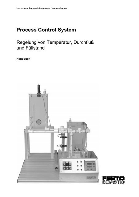
<strong>Process</strong> <strong>Control</strong> <strong>System</strong><br />
Regelung von Temperatur, Durchfluß<br />
und Füllstand<br />
Handbuch
Bestimmungsgemäße Verwendung<br />
Diese Anlage ist ausschließlich für die Aus- und Weiterbildung im<br />
Bereich Automatisierung und Kommunikation entwickelt und hergestellt.<br />
Das Ausbildungsunternehmen und / oder die Ausbildenden hat / haben<br />
dafür Sorge zu tragen, daß von den Auszubildenden die Sicherheitsvorkehrungen,<br />
die in den begleitenden Handbüchern beschrieben sind,<br />
beachtet werden.<br />
Festo Didactic schließt hiermit jegliche Haftung für Schäden des<br />
Auszubildenden, des Ausbildungsunternehmens und / oder sonstiger<br />
Dritter aus, die bei Gebrauch / Einsatz der Anlage außerhalb einer<br />
reinen Ausbildungssituation auftreten; es sei denn Festo Didactic hat<br />
solche Schäden vorsätzlich oder grob fahrlässig verursacht.<br />
Bestell-Nr.: 372 751<br />
Benennung: TECH. DOK.<br />
Bezeichnung: D.VT-TD-TFL-1-D/GB<br />
Stand: 02/1997<br />
Redaktion: Frank Ebel<br />
© Copyright by Festo Didactic KG, D-73734 Esslingen, 1997<br />
Diese Unterlage und alle in ihr enthaltenen Beiträge und Abbildungen<br />
unterliegen dem urheberrechtlichen Schutz. Jede Verwertung außerhalb<br />
der Grenzen des Urheberrechtsgesetzes und außerhalb des Unterrichts<br />
ist ohne unsere Zustimmung unzulässig. Das gilt insbesondere für<br />
Vervielfältigungen, Bearbeitungen, Übersetzungen, Mikroverfilmungen<br />
und die Einspeicherung und Verarbeitung in elektronischen <strong>System</strong>en.<br />
Teile dieser Unterlage dürfen vom berechtigten Verwender<br />
ausschließlich für Unterrichtszwecke vervielfältigt werden.
Inhaltsverzeichnis<br />
A – III<br />
Inhaltsverzeichnis<br />
A.1 Einleitung..................................................................... A1-1<br />
A.2 Arbeits- und Sicherheitshinweise .............................. A2-1<br />
A.3 Übersicht...................................................................... A3-1<br />
A.4 Mechanischer Aufbau ................................................. A4-1<br />
A.4.1 Verrohrung .................................................................... A4-2<br />
A.4.2 Erweitern von Stationen ................................................. A4-3<br />
A.4.3 Kombinieren von Stationen............................................. A4-6<br />
A.5 Bedienelemente........................................................... A5-1<br />
A.6 Beschreibung der Regelstrecken............................... A6-1<br />
A.6.1 Vernetzte Anlage mit 3 Stationen .................................. A6-1<br />
A.6.2 Durchflußregelung......................................................... A6-2<br />
A.6.3 Temperaturregelung...................................................... A6-3<br />
A.6.4 Füllstandsregelung ........................................................ A6-4<br />
A.6.5 Kompaktanlage .............................................................. A6-5<br />
A.7 Inbetriebnahme............................................................ A7-1<br />
A.7.1 Inbetriebnahme von Einzelstationen.............................. A7-1<br />
A.7.2 Inbetriebnahme der Gesamtanlage ............................... A7-2<br />
A.7.3 Reglereinstellungen....................................................... A7-4<br />
A.8 Vernetzung mit Profibus ............................................. A8-1<br />
A.9 Normen und Richtlinien .............................................. A9-1<br />
A.10 Rohrleitungs- und Instrumenten-Fließbilder ........... A10-1<br />
A.10.1 RI-Fließbild Station Durchflußregelung........................ A10-1<br />
A.10.2 RI-Fließbild Station Temperaturregelung..................... A10-2<br />
A.10.3 RI-Fließbild Station Füllstandsregelung ....................... A10-3<br />
A.10.4 RI-Fließbild Kompaktanlage ........................................ A10-4<br />
A.10.5 RI-Fließbild Gesamtanlage .......................................... A10-5<br />
Festo Didactic • <strong>Process</strong> <strong>Control</strong> <strong>System</strong>
A – IV<br />
Inhaltsverzeichnis<br />
A.11 Elektro-Mess-Steuer- und Regel-Stellenpläne......... A11-1<br />
A.11.1 EMSR Stellenplän grob, Station Durchflußregelung .... A11-1<br />
A.11.2 EMSR Stellenplän grob, Station Temperaturregelung . A11-2<br />
A.11.3 EMSR Stellenplän grob, Station Füllstandsregelung.... A11-3<br />
A.12 Stücklisten ................................................................. A12-1<br />
A.12.1 Stückliste Station Durchflußregelung ........................... A12-1<br />
A.12.2 Stückliste Station Temperaturregelung ........................ A12-2<br />
A.12.3 Stückliste Station Füllstandsregelung .......................... A12-3<br />
A.12.4 Stückliste Kompaktanlage............................................ A12-4<br />
A.12.5 Optionale Basiseinheiten und Module.......................... A12-6<br />
A.13 Datenblätter................................................................ A13-1<br />
<strong>Process</strong> <strong>Control</strong> <strong>System</strong> • Festo Didactic
Einleitung<br />
A1 – 1<br />
A.1 – Einleitung<br />
Praxisnahe Ausbildung ist die beste Vorbereitung auf den Beruf. Direkt<br />
an Produktionsanlagen auszubilden ist in den meisten Fällen nicht<br />
möglich. Zum einen wäre das Risiko einer anschließend fehlerhaft<br />
laufenden Anlage zu groß, zum anderen würde der Produktionsablauf<br />
erheblich gestört werden.<br />
Ein praxisnahes Ausbildungssystem wie das <strong>Process</strong> <strong>Control</strong> <strong>System</strong> ist<br />
eine optimale Alternative. An ihr können Auszubildende und<br />
Facharbeiter ohne Zeitdruck auf die Anforderungen im Beruf vorbereitet<br />
werden.<br />
In der Praxis soll ein Team Produktionsanlagen montieren, in Betrieb<br />
nehmen, bedienen, warten und Fehler in Anlagen lokalisieren und<br />
beseitigen.<br />
Für jedes Teammitglied bedeutet dies, daß außer der fachlichen<br />
Kompetenz zusätzliche Qualifikationen für die Teamarbeit trainiert<br />
werden, um ein effektiveres Arbeiten im Team zu ermöglichen. Die<br />
einzelnen Qualifikationen sind:<br />
• Teamfähigkeit,<br />
• Kooperationsbereitschaft,<br />
• Lernfähigkeit,<br />
• Selbständigkeit und<br />
• Organisationsvermögen.<br />
Diese Fähigkeiten und die fachliche Kompetenz werden als berufliche<br />
Handlungskompetenz bezeichnet und sind für den Mitarbeiter der<br />
Schlüssel zur beruflichen Zukunft. Für die technische Aus- und<br />
Weiterbildung in der Verfahrenstechnik bedeutet dies, neue Methoden<br />
zur Vermittlung dieser Qualifizierungsziele anzuwenden. Die Stationen<br />
und Anlagen des <strong>Process</strong> <strong>Control</strong> <strong>System</strong>s sind auf diese<br />
Qualifizierungsziele zugeschnitten.<br />
Festo Didactic • <strong>Process</strong> <strong>Control</strong> <strong>System</strong>
A1 – 2<br />
Einleitung<br />
<strong>Process</strong> <strong>Control</strong> <strong>System</strong> • Festo Didactic
Arbeits- und Sicherheitshinweise<br />
A2 – 1<br />
A.2 – Arbeits- und Sicherheitshinweise<br />
Folgende Hinweise sollten Sie im Interesse Ihrer eigenen Sicherheit<br />
beachten:<br />
Sicherheitshinweise<br />
Allgemein:<br />
r Die Auszubildenden dürfen nur unter Aufsicht einer Ausbilderin /<br />
eines Ausbilders an der Station arbeiten.<br />
r Beachten Sie die Angaben der Datenblätter zu den einzelnen<br />
Elementen, insbesondere auch alle Hinweise zur Sicherheit!<br />
Elektrik:<br />
r<br />
r<br />
Herstellen bzw. Abbauen von elektrischen Verbindungen nur in<br />
spannungslosem Zustand!<br />
Die Heizung wird mit 230 VAC betrieben. Beachten Sie die hierfür<br />
geltenden Sicherheitsbestimmungen bei der Inbetriebnahme!<br />
(DIN VDE 0113 [EN 60204])<br />
Mechanik:<br />
r<br />
r<br />
r<br />
Montieren Sie alle Elemente fest auf die Platte.<br />
Die maximale Betriebstemperatur der Behälter von +65 °C darf<br />
nicht überschritten werden.<br />
Nehmen Sie die Heizung nur in Betrieb, wenn der Heizstab völlig<br />
in die Flüssigkeit getaucht ist.<br />
Festo Didactic • <strong>Process</strong> <strong>Control</strong> <strong>System</strong>
A2 – 2<br />
Arbeits- und Sicherheitshinweise<br />
Arbeitshinweise<br />
r<br />
r<br />
Überprüfen Sie vor Inbetriebnahme der Anlage alle elektrischen<br />
Anschlüsse und alle Rohrleitungen.<br />
Füllen Sie keine verschmutzten Flüssigkeiten in die Behälter ein.<br />
Das Proportionalventil kann sonst verstopfen und die<br />
Pumpendichtungen können beschädigt werden.<br />
<strong>Process</strong> <strong>Control</strong> <strong>System</strong> • Festo Didactic
Übersicht<br />
A3 – 1<br />
A.3 – Übersicht<br />
Das <strong>Process</strong> <strong>Control</strong> <strong>System</strong> kann in der Erstausbildung, Weiterbildung<br />
und Umschulung eingesetzt werden. Das Konzept des <strong>Process</strong> <strong>Control</strong><br />
<strong>System</strong>s ist auf die Berufsbilder Prozeßleitelektroniker, Verfahrenstechniker,<br />
Ver- und Entsorger, Fachkraft für Lebensmitteltechnik, Molkereifachkraft,<br />
Brauer u.ä. zugeschnitten.<br />
Mit den Stationen und Anlagen des <strong>Process</strong> <strong>Control</strong> <strong>System</strong>s ist es<br />
möglich, die Prozesse Füllstands-, Temperatur- und Durchflußregelung<br />
zu untersuchen. Die Anlage besteht aus einzelnen Modulen, die unterschiedlich<br />
kombinierbar sind.<br />
Verschiedenen Ausbaustufen werden ermöglicht. Die Stationen und<br />
Anlagen können selbständig auf- und umgebaut, verrohrt und in Betrieb<br />
genommen werden. Sie sind somit offen für eigene Ideen, eigene Lösungsansätze<br />
und Projektarbeiten.<br />
Es werden ausschließlich industrieübliche Komponenten verwendet, um<br />
eine realitätsgetreue Ausbildung zu gewährleisten. Dieses Ausbildungskonzept<br />
ist die ideale Lösung für den verfahrenstechnischen Unterricht<br />
im Vergleich zu rein simulierten <strong>System</strong>en und großen, raumgebundenen<br />
Industrieanlagen.<br />
Folgende Lerninhalte können mit dem <strong>Process</strong> <strong>Control</strong> <strong>System</strong> vermittelt<br />
werden:<br />
• Messen nicht-elektrischer, verfahrenstechnischer sowie regelungstechnischer<br />
Größen<br />
• Erweiterung von Meßketten zu geschlossenen Regelkreisen<br />
• Aufbau, Inbetriebnahme, Änderung und Wartung von Regelkreisen<br />
• Aufbau, Verschaltung und Inbetriebnahme von Anlagen<br />
• Erweiterung, Änderung, Inbetriebnahme, Inspektion, Wartung und<br />
Instandhaltung von Prozeßleiteinrichtungen sowie Fehlerdiagnose im<br />
Störfall<br />
Festo Didactic • <strong>Process</strong> <strong>Control</strong> <strong>System</strong>
A3 – 2<br />
Übersicht<br />
Das Konzept des <strong>Process</strong> <strong>Control</strong> <strong>System</strong>s basiert auf den folgenden<br />
Punkten:<br />
• Modulares Baukastensystem, stufenweise Erweiterung ist möglich<br />
• Praxisnähe durch den Einsatz von Industriekomponenten<br />
• Leicht zu transportierendes <strong>System</strong><br />
• Betriebsmedium Wasser erlaubt gefahrloses selbständiges Arbeiten<br />
• Offen für neue Technologien wie Prozeßvisualisierung und Prozeßleittechnik<br />
über Profibus<br />
Die Grundkomponenten des <strong>Process</strong> <strong>Control</strong> <strong>System</strong>s sind:<br />
• Behälter<br />
• Pumpen<br />
• Gesteuerte Ventile<br />
• Manuell betätigte Ventile<br />
• Heizung<br />
• Kunststoff-Steckverrohrung<br />
• Sensorik:<br />
r Durchflußsensoren<br />
r Füllstandssensoren<br />
r Temperatursensoren<br />
• Industrieregler<br />
• Elektrische Bauelemente<br />
• Mechanische Bauelemente<br />
<strong>Process</strong> <strong>Control</strong> <strong>System</strong> • Festo Didactic
Übersicht<br />
A3 – 3<br />
Konfigurationsbeispiele der Stationen und Anlagen des<br />
<strong>Process</strong> <strong>Control</strong> <strong>System</strong>s:<br />
• Füllstandsregelung mit Industrieregler<br />
• Temperaturregelung mit Industrieregler<br />
• Durchflußregelung mit Industrieregler<br />
• Durchfluß-, Füllstands- und Temperaturregelung mit Industrieregler<br />
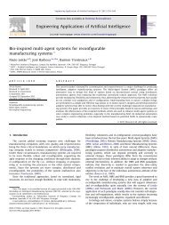
Aufbaubeispiel:<br />
Füllstandsregelung mit Industrieregler<br />
Bild 3.1:<br />
Station Füllstandsregelung<br />
Eingesetzte Komponenten:<br />
1 Pumpe 2 Behälter<br />
1 Motorregeler 1 Bedienpult<br />
1 Analoger Ultraschallsensor 1 Profilplatte<br />
1 Digitaler Industrieregler Verrohrung<br />
elektrische und mechanische<br />
Bauelemente<br />
optional:<br />
Kapazitive Näherungsschalter<br />
Festo Didactic • <strong>Process</strong> <strong>Control</strong> <strong>System</strong>
A3 – 4<br />
Übersicht<br />
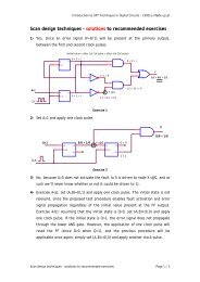
Aufbaubeispiel:<br />
Temperaturregelung mit Industrieregler<br />
Bild 3.2:<br />
Station Temperaturregelung<br />
Eingesetzte Komponenten:<br />
1 Pumpe 1 Behälter<br />
1 Heizung 1 Bedienpult<br />
1 Temperatursensor 1 Profilplatte<br />
1 Digitaler Industrieregler Verrohrung<br />
elektrische und mechanische<br />
Bauelemente<br />
optional:<br />
Kapazitive Näherungsschalter<br />
<strong>Process</strong> <strong>Control</strong> <strong>System</strong> • Festo Didactic
Übersicht<br />
A3 – 5<br />
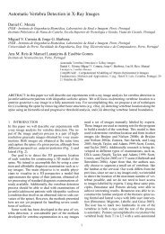
Aufbaubeispiel:<br />
Durchflußregelung mit Industrieregler<br />
Bild 3.3:<br />
Station Durchflußregelung<br />
Eingesetzte Komponenten:<br />
1 Pumpe 1 Behälter<br />
1 Motorregeler 1 Bedienpult<br />
1 Proportionalventil 1 Profilplatte<br />
1 Durchflußsensor Verrohrung<br />
1 Digitaler Industrieregler elektrische und mechanische<br />
Bauelemente<br />
optional:<br />
Kapazitive Näherungsschalter<br />
Festo Didactic • <strong>Process</strong> <strong>Control</strong> <strong>System</strong>
A3 – 6<br />
Übersicht<br />
Aufbaubeispiel:<br />
Durchfluß-, Füllstands- und Temperaturregelung mit Industrieregler<br />
(Kompaktanlage)<br />
Bild 3.4:<br />
Kompaktanlage<br />
Eingesetzte Komponenten:<br />
1 Pumpe 2 Behälter<br />
1 Motorregeler 1 Bedienpult<br />
1 Heizung 1 Profilplatte<br />
1 Durchflußsensor Verrohrung<br />
1 Temperatursensor elektrische und mechanische<br />
1 Analoger Ultraschallsensor Bauelemente<br />
1 Digitaler Industrieregler<br />
optional:<br />
Kapazitive Näherungsschalter<br />
<strong>Process</strong> <strong>Control</strong> <strong>System</strong> • Festo Didactic
Übersicht<br />
A3 – 7<br />
Alle Konfigurationen mit dem digitalen Industrieregler können mit einer<br />
Visualisierungs-Software ausgestattet werden.<br />
Bild 3.5:<br />
Visualisierungs-Software –<br />
Startbildschirm<br />
Bild 3.6:<br />
Visualisierungs-Software –:<br />
Informationen zum<br />
Pt 100 Sensor<br />
Festo Didactic • <strong>Process</strong> <strong>Control</strong> <strong>System</strong>
A3 – 8<br />
Übersicht<br />
Bild 3.7:<br />
Visualisierungs-Software –<br />
Parametereinstellung<br />
und Meßwerterfassung<br />
Kundenspezifische Konfigurationen mit SPS sind möglich.<br />
<strong>Process</strong> <strong>Control</strong> <strong>System</strong> • Festo Didactic
Mechanischer Aufbau<br />
A4 – 1<br />
A.4 – Mechanischer Aufbau<br />
Die Stationen des <strong>System</strong>s sind auf Profilplatten (700 mm x 700 mm)<br />
aufgebaut. Durch dieses Maß ergibt sich eine gute Kombinierbarkeit der<br />
einzelnen Stationen.<br />
Bild 4.1:<br />
Mechanischer Aufbau<br />
Folgende Stationen sind verfügbar:<br />
• Station TEMPERATURREGELUNG:<br />
− Regelstrecke mit Ausgleich<br />
− langsame Regelstrecke<br />
• Station DURCHFLUSSREGELUNG:<br />
− Regelstrecke mit Ausgleich<br />
− schnelle Regelstrecke<br />
• Station FÜLLSTANDSREGELUNG:<br />
− I-Regelstrecke<br />
Festo Didactic • <strong>Process</strong> <strong>Control</strong> <strong>System</strong>
A4 – 2<br />
Mechanischer Aufbau<br />
A.4.1 – Verrohrung<br />
Die Verrohrung besteht aus einem Rohr- und Steckverbindersystem aus<br />
Kunststoff. Die Verrohrung der verfahrenstechnischen Anlagen erfolgt<br />
schnell, sicher und dicht.<br />
Bild 4.2:<br />
Komponenten<br />
der Verrohrung,<br />
Rohrschneider<br />
Montage / Demontage<br />
• Zum Ablängen der Rohre wird ein Rohrschneider benötigt<br />
• Die Rohrmontage / -demontage erfolgt ohne Werkzeuge.<br />
r Montage:<br />
Das Rohr wird bis zum Anschlag in den Steckverbinder geschoben<br />
r Demontage:<br />
Zum Lösen der Verbindung wird die Klemmhülse am Steckverbinder<br />
eingedrückt und das Rohr herausgezogen.<br />
<strong>Process</strong> <strong>Control</strong> <strong>System</strong> • Festo Didactic
Mechanischer Aufbau<br />
A4 – 3<br />
A.4.2 – Erweitern von Stationen<br />
Durch den modularen Aufbau können alle Stationen einfach erweitert<br />
werden.<br />
• Integration zusätzlicher Regelstrecken:<br />
+ +<br />
Station<br />
Füllstandsregelung<br />
+ Basiseinheit<br />
Durchflußsensor<br />
+ Basiseinheit<br />
Proportionalventil<br />
Sie erhalten die Regelstrecken Füllstand und Durchfluß.<br />
Festo Didactic • <strong>Process</strong> <strong>Control</strong> <strong>System</strong>
A4 – 4<br />
Mechanischer Aufbau<br />
• Ersetzen von Handventilen durch Magnetventile:<br />
+<br />
Station<br />
Füllstandsregelung<br />
+ Basiseinheit<br />
Magnetventil<br />
LI<br />
30<br />
LIC<br />
30<br />
V el.<br />
V ab<br />
P<br />
a<br />
Sie erhalten eine elektrisch zuschaltbare Störgröße (z.B. Öffnen eines<br />
Bypasses).<br />
<strong>Process</strong> <strong>Control</strong> <strong>System</strong> • Festo Didactic
Mechanischer Aufbau<br />
A4 – 5<br />
• Füllstandsüberwachung<br />
Mit Hilfe von kapazitiven Näherungsschaltern läßt sich eine Füllstandsüberwachung<br />
realisieren.<br />
Mit einem Haltewinkel werden die Näherungsschalter an einem Profilstab<br />
befestigt. Die Näherungsschalter können stufenlos in der Höhe<br />
verschoben werden.<br />
Das Ausgangssignal wird über den Binäreingang an den Regler geleitet.<br />
0 V 24 V Out Alarm Out B1 Pt100 IN Bin<br />
+<br />
S<br />
-<br />
1<br />
2<br />
3<br />
+<br />
-<br />
1<br />
2<br />
-<br />
+<br />
+<br />
+<br />
+<br />
-<br />
-<br />
-<br />
-<br />
Analog Terminal<br />
BN<br />
BK<br />
BU<br />
BU<br />
BK<br />
BN<br />
BK<br />
BU<br />
H2<br />
B<br />
Pt100<br />
230V/115V<br />
PE<br />
L1<br />
N<br />
H1<br />
S2<br />
S1<br />
M<br />
P<br />
24VDC<br />
0VDC<br />
Durch Konfiguration des Reglers im Menü 'Zusätze', 'Bin Ein' kann<br />
ein Alarm bei<br />
− unterschreiten eines Füllstandes (Wirksinn 'Inv: Ja')<br />
oder<br />
− überschreiten eines Füllstandes (Wirksinn 'Inv = Nein')<br />
ausgelöst werden.<br />
Festo Didactic • <strong>Process</strong> <strong>Control</strong> <strong>System</strong>
A4 – 6<br />
Mechanischer Aufbau<br />
A.4.3 – Kombinieren von Stationen<br />
Einzelne Stationen können mit Profilverbinden verbunden werden.<br />
Mit einer zusätzlichen Pumpe und zwei Ventilen pro Station können Stationen<br />
zur Weiterleitung der Flüssigkeit miteinander verbunden werden.<br />
Bild 4.3:<br />
Kombination von<br />
Stationen zu Anlagen<br />
V3<br />
V1<br />
V4<br />
V2<br />
V4<br />
V2<br />
P<br />
V3<br />
V1<br />
P<br />
Die Ventile können als Handventile, Magnetventile oder als Kombination<br />
der beiden Ventiltypen ausgeführt sein.<br />
Die Ansteuerung kann somit von Hand, über eine Relaissteuerung oder<br />
über eine Speicherprogrammierbare Steuerung erfolgen.<br />
<strong>Process</strong> <strong>Control</strong> <strong>System</strong> • Festo Didactic
Bedienelemente<br />
A5 – 1<br />
A.5 – Bedienelemente<br />
In einem Bedienpult sind alle Komponenten zur Bedienung der<br />
Stationen zusammengefaßt.<br />
Bild 5.1:<br />
Bedienpult<br />
• Funktion der Schalter:<br />
− S1 EIN / AUS: Betriebsspannung Ein / Aus<br />
− S2 PUMPE: Reglerstellgröße wirkt auf Pumpe /<br />
Pumpe läuft konstant<br />
− S3 VENTIL: Proportionalventil geschlossen /<br />
Reglerstellgröße wirkt auf<br />
Proportionalventil<br />
− S4 EXTERNE<br />
FUNKTION: Frei konfigurierbar<br />
• Funktion der Leuchtmelder:<br />
− H1 STEUERUNG<br />
EIN:<br />
Betriebsspannung Ein<br />
− H2 ALARM: Alarm<br />
• Belegung der Meßbuchsen:<br />
− An die Meßbuchsen können individuell Prozeßsignale gelegt<br />
werden, die mit externen Meßgeräten oder Schreibern<br />
ausgewertet werden sollen.<br />
Standard-Belegung<br />
• I: X-Meßsignal Durchflußsensor (0 ... 1 kHz)<br />
• II: Y-Meßsignal Stellgröße (0 ... 10 V)<br />
• III: ext. SP Anschlußmöglichkeit für externen<br />
Sollwertgeber (z.B. 0 ... 10 V; Regler muß<br />
auf 'Struktur/extern W' geschaltet sein<br />
[siehe Reglerhandbuch])<br />
Festo Didactic • <strong>Process</strong> <strong>Control</strong> <strong>System</strong>
A5 – 2<br />
Bedienelemente<br />
• Analog-Terminal<br />
Über das Analog-Terminal werden Sensoren, Aktoren und<br />
Bedienelemente an den eingesetzten Industrieregler angeschlossen.<br />
− Eingänge<br />
Pt 100<br />
Level (0 ... 20 mA)<br />
Flow (0 ... 1 kHz)<br />
S. Funct. (0 ... 1 kHz)<br />
ext. Sp. (0 ... 10 V)<br />
In Bin (0 / 24 V)<br />
Reglereingang 1 'Istwert'<br />
Die Umstellung zwischen:<br />
• Pt 100,<br />
• Level und<br />
• Flow<br />
erfolgt am Regler in den entsprechenden<br />
Konfigurationsmenüs oder mit der<br />
Visualisierungs-Software<br />
Reglereingang 2<br />
am Regler konfigurierbar für :<br />
• Störgrößenaufschaltung<br />
• Kaskadenregelung<br />
• Folgeregelung<br />
• Verhältnisregelung oder<br />
• externer Sollwert<br />
Binäreingang<br />
am Regler konfigurierbar für:<br />
• Auslösen von Alarm<br />
• Umschalten Hand / Automatik<br />
• Umschalten externer / interner Sollwert<br />
− Ausgänge<br />
Out U (0 ... 10 V)<br />
Out I (0 ... 20 mA)<br />
Out B1 (0 / 24 V)<br />
Out B2 (0 / 24 V)<br />
Out B3 (0 / 24 V)<br />
Out Alarm (0 / 24 V; 24 / 0 V)<br />
Reglerausgang 'Stellgröße'<br />
am Regler konfigurierbar als:<br />
• stetiger Ausgang (0 ... 10 V, 0 ... 20 mA)<br />
• 2-Punkt pulsweitenmodulierter Ausgang (B1)<br />
• 3-Punkt pulsweitenmodulierter Ausgang<br />
(B1, B2)<br />
Binärausgang<br />
am Regler konfigurierbar für:<br />
• Meldung Alarm<br />
• Meldung Fehler<br />
• Meldung Hand<br />
Ausgang für Alarmmeldung<br />
(invertiert oder nicht invertiert)<br />
<strong>Process</strong> <strong>Control</strong> <strong>System</strong> • Festo Didactic
Beschreibung der Regelstrecken<br />
A6 – 1<br />
A.6 – Beschreibung der Regelstrecken<br />
A6.1 – Vernetzte Anlage mit 3 Stationen<br />
Mit der vernetzten Anlage ist es möglich, die Prozesse Füllstands-,<br />
Temperatur- und Durchflußregelung zu untersuchen.<br />
LI<br />
30<br />
LIC<br />
30<br />
FIC<br />
20<br />
TIC<br />
10<br />
V ab<br />
a<br />
P<br />
V ab<br />
HSO<br />
FI<br />
LIA -<br />
20<br />
20<br />
TI LS<br />
10 10 10<br />
V ab<br />
P<br />
a<br />
P<br />
Bild 6.1:<br />
Fließbild der vernetzten Anlage<br />
Die Behälter sind durch Rohre verbunden. Mit den Pumpen P wird die<br />
Flüssigkeit umgepumpt.<br />
Die Absperrhähne bzw. Magnetventile sind zum Einstellen der<br />
verschiedenen Prozeßarten und zur Störungsaufschaltung zu<br />
verwenden.<br />
Als universelle Regler für die Prozesse Füllstands-, Temperatur- und<br />
Durchflußregelung werden digitale Industrieregler eingesetzt.<br />
Festo Didactic • <strong>Process</strong> <strong>Control</strong> <strong>System</strong>
A6 – 2<br />
Beschreibung der Regelstrecken<br />
A.6.2 – Durchflußregelung<br />
An der aufgebauten Durchflußregelstrecke kommen zwei Betriebsarten<br />
zum Einsatz:<br />
• Durchflußregelung mit Hilfe eines Proportionalventils.<br />
Die Stellgröße ist hier der Hub des Ventilkolbens, die Pumpe P läuft<br />
konstant.<br />
• Durchflußregelung mit Hilfe der Pumpe.<br />
Stellgröße ist hier die Drehzahl der Pumpe.<br />
Das Umstellen zwischen den beiden Betriebsarten ist durch<br />
handbetätigte Absperrhähne einfach möglich.<br />
Bild 6.2:<br />
Fließbild Durchflußregelung<br />
FIC<br />
20<br />
HSO<br />
20<br />
V ab<br />
P<br />
FI<br />
20<br />
a<br />
<strong>Process</strong> <strong>Control</strong> <strong>System</strong> • Festo Didactic
Beschreibung der Regelstrecken<br />
A6 – 3<br />
A.6.3 – Temperaturregelung<br />
An der aufgebauten Temperaturregelstrecke kann die Temperatur einer<br />
Flüssigkeit mit einer Heizung erhöht werden. Um eine ständige<br />
Durchmischung der Flüssigkeit zu gewährleisten, wird die Flüssigkeit mit<br />
der Pumpe P ständig umgewälzt.<br />
Beachten Sie die maximale Betriebstemperatur der Behälter<br />
von +65 °C<br />
Nehmen Sie die Heizung nur in Betrieb, wenn der Heizstab völlig in die<br />
Flüssigkeit getaucht ist.<br />
Bild 6.3:<br />
TIC<br />
Fließbild<br />
10<br />
Temperaturregelung<br />
LIA -<br />
10<br />
TI<br />
10<br />
LS<br />
10<br />
P<br />
Festo Didactic • <strong>Process</strong> <strong>Control</strong> <strong>System</strong>
A6 – 4<br />
Beschreibung der Regelstrecken<br />
A.6.4 – Füllstandsregelung<br />
An der aufgebauten Füllstandsregelstrecke kann die Füllhöhe der<br />
Flüssigkeit in einem Behälter geregelt werden.<br />
• Der Füllstand der Flüssigkeit wird mit einem analogen<br />
Ultraschallsensor ermittelt.<br />
• Zur Störung der Regelstrecke kann die Flüssigkeit durch teilweises<br />
oder vollständiges Öffnen des Absperrhahns in den unteren Behälter<br />
abgelassen werden.<br />
Bild 6.4:<br />
Füllstandsregelung<br />
LI<br />
30<br />
LIC<br />
30<br />
V ab<br />
P<br />
a<br />
<strong>Process</strong> <strong>Control</strong> <strong>System</strong> • Festo Didactic
Beschreibung der Regelstrecken<br />
A6 – 5<br />
A.6.5 – Kompaktanlage<br />
Bei der Kompaktanlage sind die Regelstrecken Durchfluß, Temperatur<br />
und Füllstand durch entsprechende Umschaltung der Ventile bzw.<br />
Konfiguration des Reglers möglich.<br />
LI<br />
30<br />
Bild 6.5:<br />
Fließbild Kompaktanlage<br />
TI<br />
10<br />
LIA -<br />
10<br />
FIC<br />
20<br />
HSO<br />
20<br />
V ab<br />
P<br />
FI<br />
20<br />
a<br />
Festo Didactic • <strong>Process</strong> <strong>Control</strong> <strong>System</strong>
A6 – 6<br />
Beschreibung der Regelstrecken<br />
<strong>Process</strong> <strong>Control</strong> <strong>System</strong> • Festo Didactic
Inbetriebnahme<br />
A7 – 1<br />
A.7 – Inbetriebnahme<br />
A.7.1 – Inbetriebnahme von Einzelstationen<br />
r Überprüfen Sie vor Inbetriebnahme der Anlage alle elektrischen<br />
Anschlüsse und alle Rohrleitungen!<br />
r Füllen Sie 10 bis 12 l Wasser in den Behälter ein.<br />
Die Verwendung von destilliertem Wasser sorgt für eine längere<br />
wartungsfreie Betriebsdauer der Anlage.<br />
(Proportionalventil, Pumpen)<br />
r Überprüfen Sie die Dichtigkeit der Leitungsanschlüsse und der<br />
Verrohrung der Anlage.<br />
r Schalten Sie die 24 VDC Steuerspannung ein.<br />
r Zum Entlüften der Pumpe schalten Sie diese eventuell mehrmals ein<br />
und aus.<br />
Festo Didactic • <strong>Process</strong> <strong>Control</strong> <strong>System</strong>
A7 – 2<br />
Inbetriebnahme<br />
A.7.2 – Inbetriebnahme der Gesamtanlage<br />
r Überprüfen Sie vor Inbetriebnahme der Anlage alle elektrischen<br />
Anschlüsse und alle Rohrleitungen!<br />
r Zum Befüllen den Behälter B mit destilliertem Wasser füllen.<br />
In der gesamten Anlage darf nicht mehr Wasser sein, wie dieser eine<br />
Behälter faßt.<br />
r Ventil h a schließen<br />
r Ventil h b schließen<br />
r Ventil h c öffnen<br />
h a<br />
h c<br />
B<br />
h b<br />
P<br />
<strong>Process</strong> <strong>Control</strong> <strong>System</strong>• Festo Didactic
Inbetriebnahme<br />
A7 – 3<br />
r Mit der Pumpe P das Wasser in die anderen Teilstationen pumpen,<br />
damit in jeder Station mindestens soviel Wasser ist, daß der jeweils<br />
untere Füllstandssensor an den jeweiligen Behältern anspricht.<br />
zur Station Durchflußregelung<br />
zur Station Temperaturregelung<br />
zur Station<br />
Füllstandsregelung<br />
h6<br />
h5<br />
h4<br />
h3<br />
h2<br />
h1<br />
Dazu die Handventile h1 bis h6 wie in der Tabelle beschrieben<br />
betätigen:<br />
h1 h2 h3 h4 h5 h6 Station<br />
Temperaturregelung<br />
Füllstand der Behälter<br />
Station<br />
Durchflußregelung<br />
Station<br />
Füllstandsregelung<br />
zu auf zu zu zu auf<br />
b<br />
a<br />
b<br />
a<br />
b<br />
a<br />
auf zu zu zu zu auf<br />
b<br />
a<br />
zu zu zu auf zu auf<br />
b<br />
a<br />
zu zu auf zu zu auf<br />
b<br />
a<br />
r h b öffnen, h6 schließen<br />
h c schließen, Pumpe aus<br />
h a öffnen<br />
r Die Verwendung von destilliertem Wasser sorgt für eine längere<br />
wartungsfreie Betriebsdauer der Anlage.<br />
(Proportionalventil, Pumpen)<br />
r Überprüfen Sie die Dichtigkeit der Leitungsanschlüsse und der<br />
Verrohrung der Anlage.<br />
r Schalten Sie die 24 VDC Steuerspannung ein.<br />
r Zum Entlüften der Pumpen schalten Sie diese eventuell mehrmals<br />
ein und aus.<br />
Festo Didactic • <strong>Process</strong> <strong>Control</strong> <strong>System</strong>
A7 – 4<br />
Inbetriebnahme<br />
A.7.3 – Reglereinstellungen<br />
(Ausführliche Informationen über das Bedienen des Reglers, entnehmen Sie bitte der<br />
Bedienungsanleitung des Reglers, Kapitel 6. Beachten Sie die Hinweise zur Sicherheit<br />
in der Bedienungsanleitung des Reglers.)<br />
Der Industrieregler läßt sich über verschiedene Menüs konfigurieren. In<br />
die Konfigurierebene des Reglers gelangt man durch gleichzeitiges<br />
Drücken der SELECT- und ENTER-Taste (5 sec. lang).<br />
Temperaturregelung<br />
Durchflußregelung<br />
Füllstandsregelung<br />
Struktur standard standard standard<br />
Eingang1 Pt100 3-Draht Frequenz 0-20mA<br />
- Fre: 1000 Rad: aus<br />
Skalierung - X1o 100.0 X1o 100.0<br />
- X1u 0.00 X1u 0.00<br />
Sollwertgrenzen W1o 60.00 W1o 100.0 W1o 100.0<br />
W1u 0.00 W1u 0.00 W1u 0.00<br />
Alarm-Modus Al abs Al abs Al abs<br />
Alarmgrenzen X1+ 60.00 X1+ 100.0 X1+ 100.0<br />
X1- 0.00 X1- 0.00 X1- 0.00<br />
Hy 1.00 Hy 1.00 Hy 1.00<br />
Filter Fg1 20.00 Fg1 20.00 Fg1 20.00<br />
Regler Kp 4.00 Kp 3.50 Kp 28<br />
Tn 2500 Tn 0.40 Tn 5.00<br />
Tv 0.00 Tv 0.00 Tv 0.00<br />
Y0 0.00 Y0 0.00 Y0 0.00<br />
Ausgang 2Pkt-PWM stetig stetig<br />
Signalart 0-10V 0-10V<br />
Periodendauer T+ 10.00<br />
Stellgrößen- Yo 100.0 Yo 100.0 Yo 100.0<br />
begrenzung Yu 0.00 Yu 0.00 Yu 0.00<br />
Wirkungssinn Inv nein Inv nein Inv nein<br />
Impulsausgang Imp nein<br />
Sicherh<br />
Ys 0.00 Ys 0.00 Ys 0.00<br />
Adap.Reg<br />
Tune aus Tune aus Tune aus<br />
Adapt aus Adapt aus Adapt aus<br />
Zusätze<br />
mit Visualisierungs-<br />
Software<br />
Sprache Deutsch Sprache Deutsch Sprache Deutsch<br />
Seriell remote Seriell remote Seriell remote<br />
Profibus Addr 002 Addr 003 Addr 005<br />
RS232 Addr 1 Addr 1 Addr 1<br />
BinEin nicht BinEin nicht BinEin nicht<br />
BinAus nicht BinAus nicht BinAus nicht<br />
Rampe aus Rampe aus Rampe aus<br />
SPT aus SPT aus SPT aus<br />
Zeile2 Istw Zeile2 Istw Zeile2 Istw<br />
Code - Code - Code -<br />
<strong>Process</strong> <strong>Control</strong> <strong>System</strong>• Festo Didactic
Vernetzung mit Profibus<br />
A8 – 1<br />
A.8 – Vernetzung mit Profibus<br />
Die Vernetzung der verfahrenstechnischen Gesamtanlage wird mit dem<br />
Feldbus Profibus realisiert.<br />
Leitrechner /<br />
Prozeßvisualisierung<br />
Bild 8.1:<br />
Vernetzung der<br />
Gesamtanlage mit Profibus<br />
Profibus<br />
Knoten 1 Knoten 2 Knoten 3 Knoten 4<br />
Temperatur Durchfluß Füllstand<br />
SPS Regler Regler Regler<br />
Addr. 4 Addr. 2 Addr. 3 Addr. 5<br />
Prozesse<br />
Mit Hilfe einer Prozeßvisualisierungssoftware werden die benötigten Einund<br />
Ausgangssignale der einzelnen Prozesse der Gesamtanlage<br />
gesteuert.<br />
• Pinbelegung<br />
1 Schirm<br />
3 Data +<br />
5 Datenbezug GND<br />
8 Data –<br />
1<br />
2<br />
3<br />
4<br />
5<br />
6<br />
7<br />
8<br />
9<br />
6<br />
7<br />
8<br />
9<br />
1<br />
2<br />
3<br />
4<br />
5<br />
Der Schirm darf niemals an die Datenbezugsleitung Pin 5<br />
angeschlossen werden.<br />
Festo Didactic • <strong>Process</strong> <strong>Control</strong> <strong>System</strong>
A8 – 2<br />
Vernetzung mit Profibus<br />
• Busabschluß<br />
Beim ersten und letzten Knoten, hier den Knoten 1 und 4, muß ein<br />
Busabschluß vorgenommen werden. Dies läßt sich bei vielen<br />
Profibusteilnehmern über DIP-Schalter einstellen. Der Busabschluß<br />
entspricht der abgebildeten Schaltung.<br />
390 Ohm, 1/4 W150 Ohm, 1/4 W 390 Ohm, 1/4 W<br />
5V<br />
(Pin 6)<br />
Data +<br />
(Pin 3)<br />
Data -<br />
(Pin 8)<br />
GND<br />
(Pin 5)<br />
• Verschaltung<br />
Die einzelnen Komponenten werden wie in der folgenden Tabelle<br />
dargestellt verschaltet.<br />
lfd. Nr. Verbindung von nach<br />
1 Profibus-Einsteckkarte PC Profibus T-Verteiler 1<br />
Teilanlage Temperaturregelung<br />
2 Profibus T-Verteiler 1<br />
Teilanlage Temperaturregelung<br />
a) SPS<br />
b) Profibus T-Verteiler 2<br />
Teilanlage Temperaturregelung<br />
3 Profibus T-Verteiler 2<br />
Teilanlage Temperaturregelung<br />
4 Profibus T-Verteiler<br />
Teilanlage Durchflussregelung<br />
5 Profibus T-Verteiler<br />
Teilanlage Füllstandsregelung<br />
a) Industrieregler<br />
Temperaturregelung<br />
b) Profibus T-Verteiler<br />
Teilanlage Durchflussregelung<br />
a) Industrieregler<br />
Durchflussregelung<br />
b) Profibus T-Verteiler<br />
Teilanlage Füllstandsregelung<br />
a) Industrieregler<br />
Füllstandsregelung<br />
<strong>Process</strong> <strong>Control</strong> <strong>System</strong> • Festo Didactic
Normen und Richtlinien<br />
A9 – 1<br />
A.9 – Normen und Richtlinien<br />
DIN VDE 0100<br />
DIN VDE 0113/<br />
EN 60204<br />
VDI/VDE 2180<br />
VDI 2880<br />
DIN 19 226<br />
DIN 19 227<br />
DIN 19 235<br />
DIN 19 239<br />
DIN 19 240<br />
Bestimmungen für das Errichten von Starkstromanlagen<br />
bei Nennspannungen bis 1000 V<br />
Elektrische Ausrüstung von Industriemaschinen;<br />
Allgemeine Festlegungen<br />
Sicherung von Anlagen der Verfahrenstechnik<br />
mit Mitteln der Meß-, Steuerungs- und<br />
Regelungstechnik;<br />
Blatt 1: Einführung, Begriffe, Erklärungen<br />
Blatt 5: Bauliche und installationstechnische<br />
Maßnahmen zur Funktionssicherung<br />
von Meß-, Steuerungs- und Regeleinrichtungen in<br />
Ausnahmezuständen<br />
Speicherprogrammierbare Steuerungsgeräte;<br />
Blatt 1: Definitionen und Kenndaten<br />
Blatt 2: Prozeß- und Datenschnittstellen<br />
Blatt 3: Programmier- und Testeinrichtungen<br />
Blatt 4: Programmiersprachen<br />
Blatt 5: Sicherheitstechnische Grundsätze<br />
Messen, Steuern, Regeln;<br />
Regelungstechnik und Steuerungstechnik;<br />
Teil 5: Funktionelle und gerätetechnische Begriffe<br />
Messen, Steuern, Regeln;<br />
Grapische Symbole und Kennbuchstaben für die<br />
Prozeßleittechnik<br />
Messen, Steuern, Regeln;<br />
Meldung von Betriebszuständen<br />
Messen, Steuern, Regeln;<br />
Speicherprogrammierte Steuerungen,<br />
Programmierung<br />
Messen, Steuern, Regeln;<br />
Peripherie-Schnittstellen elektronischer Steuerungen;<br />
Stromversorgung und binäre Schnittstellen<br />
Festo Didactic • <strong>Process</strong> <strong>Control</strong> <strong>System</strong>
A9 – 2<br />
Normen und Richtlinien<br />
DIN 28 004<br />
DIN 40 719<br />
DIN 40 900<br />
DIN 45 140<br />
Fließbilder verfahrenstechnischer Anlagen;<br />
Begriffe, Fließbildarten, Informationsinhalt<br />
Schaltungsunterlagen;<br />
Teil 6: Regeln für Funktionspläne,<br />
IEC 848 modifiziert<br />
Teil 60: Ausführung von Funktionsplänen für Messen,<br />
Steuern, Regeln<br />
Graphische Symbole für Schaltunterlagen;<br />
Teil 7: Schaltzeichen für Schalt- und Schutzeinrichtungen<br />
Teil 12: Binäre Elemente<br />
Messen, Steuern, Regeln;<br />
Anschlußkennzeichnung von MSR-Geräten,<br />
Teil 1: Festlegung des alphanumerischen <strong>System</strong>s<br />
Teil 2: Ausführung des Übersetzungsschlüssels<br />
<strong>Process</strong> <strong>Control</strong> <strong>System</strong>• Festo Didactic
Fließbilder<br />
A10 – 1<br />
A.10 – Rohrleitungs- und Instrumenten - Fließbilder<br />
A.10.1 – RI - Fließbild Station Durchflußregelung<br />
FIC<br />
20<br />
HSO<br />
20<br />
V ab<br />
P<br />
FI<br />
20<br />
a<br />
Festo Didactic • <strong>Process</strong> <strong>Control</strong> <strong>System</strong>
A10 – 2<br />
Fließbilder<br />
A.10.2 – RI - Fließbild Station Temperaturregelung<br />
TIC<br />
10<br />
LIA -<br />
TI LS<br />
10 10 10<br />
V ab<br />
P<br />
<strong>Process</strong> <strong>Control</strong> <strong>System</strong>• Festo Didactic
Fließbilder<br />
A10 – 3<br />
A.10.3 – RI - Fließbild Station Füllstandsregelung<br />
LI<br />
30<br />
LIC<br />
30<br />
V ab<br />
P<br />
a<br />
Festo Didactic • <strong>Process</strong> <strong>Control</strong> <strong>System</strong>
A10 – 4<br />
Fließbilder<br />
A.10.4 – RI - Fließbild Kompaktanlage<br />
LI<br />
30<br />
TI<br />
10<br />
LIA -<br />
10<br />
FIC<br />
20<br />
HSO<br />
20<br />
V ab<br />
P<br />
FI<br />
20<br />
a<br />
<strong>Process</strong> <strong>Control</strong> <strong>System</strong>• Festo Didactic
Fließbilder<br />
A10 – 5<br />
A.10.5 – RI - Fließbild Gesamtanlage<br />
LI<br />
30<br />
V ab<br />
a<br />
LIC<br />
30<br />
P<br />
V ab<br />
a<br />
FIC<br />
20<br />
HSO<br />
20<br />
P<br />
FI<br />
20<br />
TIC<br />
10<br />
LIA -<br />
TI LS<br />
10 10 10<br />
V ab<br />
P<br />
Festo Didactic • <strong>Process</strong> <strong>Control</strong> <strong>System</strong>
A10 – 6<br />
Fließbilder<br />
<strong>Process</strong> <strong>Control</strong> <strong>System</strong>• Festo Didactic
EMSR Stellenpläne<br />
A11 – 1<br />
A.11 – Elektro-Mess-Steuer- und Regel-Stellenpläne<br />
A11.1 – EMSR Stellenplan grob, Station Durchflußregelung<br />
Leitwarte<br />
Schaltraum<br />
Feld<br />
Festo Didactic • <strong>Process</strong> <strong>Control</strong> <strong>System</strong>
A11 – 2<br />
EMSR Stellenpläne<br />
A11.2 – EMSR Stellenplan grob, Station Temperaturregelung<br />
Leitwarte<br />
Schaltraum<br />
Feld<br />
<strong>Process</strong> <strong>Control</strong> <strong>System</strong> • Festo Didactic
EMSR Stellenpläne<br />
A11 – 3<br />
A11.3 – EMSR Stellenplan grob, Station Füllstandsregelung<br />
Leitwarte<br />
Schaltraum<br />
Feld<br />
Festo Didactic • <strong>Process</strong> <strong>Control</strong> <strong>System</strong>
A11 – 4<br />
EMSR Stellenpläne<br />
<strong>Process</strong> <strong>Control</strong> <strong>System</strong> • Festo Didactic
Stücklisten<br />
A12 – 1<br />
A.12 – Stücklisten<br />
A.12.1 – Stückliste Station Durchflußregelung<br />
• mit Bürkert-Regler: Best.-Nr. 170 668<br />
Pos. Best.-Nr. Menge Benennung<br />
1 170 711 1 Durchflußsensor<br />
2 170 712 1 Pumpe<br />
3 170 698 1 Motorregler<br />
4 170714 1 Proportionalventil<br />
5 170 716 1 Kugelhahn<br />
6 170 696 1 Regler Bürkert 1110<br />
7 170 699 1 Analog-Terminal<br />
8 170 708 1 Bedienpult<br />
9 170 707 1 Behälter<br />
10 007 658 1 Rohrschneider<br />
11 170 700 5 Rohrstück<br />
12 170 701 6 Winkel-Verbinder<br />
13 170 702 2 T-Verbinder<br />
14 170 703 1 Handventil<br />
15 159 410 1 Profilplatte 700 mm x 700 mm<br />
Festo Didactic • <strong>Process</strong> <strong>Control</strong> <strong>System</strong>
A12 – 2<br />
Stücklisten<br />
A.12.2 – Stückliste Station Temperaturregelung<br />
• mit Bürkert-Regler: Best.-Nr. 170 667<br />
Pos. Best.-Nr. Menge Benennung<br />
1 170 709 1 Temperatursensor<br />
2 170 712 1 Pumpe<br />
3 170 713 1 Heizung<br />
4 170 716 1 Kugelhahn<br />
5 170 696 1 Regler Bürkert 1110<br />
6 170 699 1 Analog-Terminal<br />
7 170 708 1 Bedienpult<br />
8 170 707 1 Behälter<br />
9 007 658 1 Rohrschneider<br />
10 170 700 5 Rohrstück<br />
11 170 701 5 Winkel-Verbinder<br />
12 159 410 1 Profilplatte 700 mm x 700 mm<br />
<strong>Process</strong> <strong>Control</strong> <strong>System</strong>• Festo Didactic
Stücklisten<br />
A12 – 3<br />
A.12.3 – Stückliste Station Füllstandsregelung<br />
• mit Bürkert-Regler: Best.-Nr. 170 669<br />
Pos. Best.-Nr. Menge Benennung<br />
1 170 710 1 Analoger Ultraschallsensor<br />
2 170 712 1 Pumpe<br />
3 170 698 1 Motorregler<br />
4 170 716 1 Kugelhahn<br />
5 170 696 1 Regler Bürkert 1110<br />
6 170 699 1 Analog-Terminal<br />
7 170 708 1 Bedienpult<br />
8 170 707 2 Behälter<br />
9 007 658 1 Rohrschneider<br />
10 170 700 5 Rohrstück<br />
11 170 701 8 Winkel-Verbinder<br />
12 170 703 2 Handventil<br />
13 170 704 1 Rückschlagventil<br />
14 159 410 1 Profilplatte 700 mm x 700 mm<br />
Festo Didactic • <strong>Process</strong> <strong>Control</strong> <strong>System</strong>
A12 – 4<br />
Stücklisten<br />
A.12.4 – Stückliste Kompaktanlage<br />
• mit Bürkert-Regler: Best.-Nr. 170 666<br />
Pos. Best.-Nr. Menge Benennung<br />
1 170 711 1 Durchflußsensor<br />
2 170 709 1 Temperatursensor<br />
3 170 710 1 Analoger Ultraschallsensor<br />
4 170 712 1 Pumpe<br />
5 170 698 1 Motorregler<br />
6 170 713 1 Heizung<br />
7 170 716 1 Kugelhahn<br />
8 170 696 1 Regler Bürkert 1110<br />
9 170 699 1 Analog-Terminal<br />
10 170 708 1 Bedienpult<br />
11 170 707 2 Behälter<br />
12 007 658 1 Rohrschneider<br />
13 170 700 5 Rohrstück<br />
14 170 701 9 Winkel-Verbinder<br />
15 170 702 1 T-Verbinder<br />
16 170 703 3 Handventil<br />
17 170 704 1 Rückschlagventil<br />
18 159 410 1 Profilplatte 700 mm x 700 mm<br />
<strong>Process</strong> <strong>Control</strong> <strong>System</strong>• Festo Didactic
Stücklisten<br />
A12 – 5<br />
Festo Didactic • <strong>Process</strong> <strong>Control</strong> <strong>System</strong>
A12 – 6<br />
Stücklisten<br />
A.12.5 – Optionale Basiseinheiten und Module<br />
Pos. Best.-Nr. Menge Benennung<br />
1 258 172 – Kapazitiver Näherungsschalter<br />
2 326 351 – Haltewinkel für Pos. 1<br />
3 109 383 – Profil, 32 x 32 x 318<br />
4 170 715 – 2/2-Wege-Magnetventil<br />
5 170 697 – Serielle und Profibus-FMS Einsteckkarte<br />
für Bürkert-Regler (Best.-Nr. 170 696)<br />
<strong>Process</strong> <strong>Control</strong> <strong>System</strong>• Festo Didactic
Datenblätter<br />
A13 – 1<br />
A.13 – Datenblätter<br />
Festo Didactic • <strong>Process</strong> <strong>Control</strong> <strong>System</strong>
A13 – 2<br />
Datenblätter<br />
lfd. Nr. Benennung Best.-Nr.<br />
1 Bürkert Regler 170 696<br />
2 Motorregler 170 698<br />
3 Analog-Terminal 170 699<br />
4 Verrohrung 170 701<br />
5 Behälter 170 707<br />
6 Temperatursensor 170 709<br />
7 Analoger Ultraschallsensor 170 710<br />
8 Durchflußsensor 170 711<br />
9 Pumpe 170 712<br />
10 Heizung 170 713<br />
11 Proportionalventil 170 714<br />
12 2/2-Wege-Magnetventil 170 715<br />
13 Kugelhahn 170 716<br />
14 Kapazitiver Näherungsschalter 258 172<br />
Die Datenblätter sind nach der Bestellnummer geordnet.<br />
<strong>Process</strong> <strong>Control</strong> <strong>System</strong>• Festo Didactic
Regler 170696<br />
1/2<br />
Aufbau<br />
Der Regler ist in einem Gehäuse montiert. Der Regler wird im Bedienpult eingebaut.<br />
Funktion<br />
Der universelle Digitalregler ist für die Verwendung in Einzelregelkreisen bis hin zur<br />
Automatisierung in Verfahrensprozessen geeignet. Standardmäßig ist eine Selbstoptimierung<br />
eingebaut, die nach FUZZY-Algorithmen arbeitet.<br />
Die Konfiguration erfolgt softwaremäßig. Er besitzt eine zweizeilige alphanumerische<br />
LCD-Anzeige. Die Konfigurations- und Parametereinstellungen werden nichtflüchtig gespeichert.<br />
Hinweis<br />
Beachten Sie die Hinweise in der Bedienungsanleitung.<br />
Regelalgorithmen<br />
PID<br />
Verstärkung<br />
Nachstellzeit<br />
Vorhaltezeit<br />
2 Pkt, 3 Pkt, 3-Pkt-Schritt, stetig<br />
0,1 ... 999,9<br />
0,4 ... 9999 s<br />
0,4 ... 9999 s<br />
Anzeige<br />
LCD<br />
Zifferngröße<br />
Versorgungsspannung<br />
2 x 8 Zeichen<br />
10 x 6 mm<br />
24 VAC<br />
Betriebsumgebungstemperatur 0 ... +55 °C<br />
Ausgänge<br />
Relais<br />
Strom<br />
Spannung<br />
Wirksinn<br />
2 potentialfreie Wechsler, 250 VAC / 5 A<br />
0 / 4 ... 20 mA, max. Last 440 Ω,<br />
0 ... 10 V, max. Laststrom 5 mA<br />
bei stetigem und 2-Punkt-Ausgang umkehrbar<br />
Binärausgang<br />
Konfigurierbar für:<br />
• Alarmfunktion<br />
• Manuell/Automatik Betrieb<br />
• Fühler oder int. Fehler<br />
log. 0 = offen<br />
log. 1 = 17,5 ... 24 V<br />
Ausgangsstrom: 20 mA<br />
Kurzschlussfest<br />
Technische Daten<br />
Festo Didactic
170696 Regler<br />
2/2<br />
Technische Daten<br />
(Fortsetzung)<br />
Eingänge<br />
Messeingang 1<br />
Messeingang 2<br />
Konfigurierbar für:<br />
• ext. Sollwert<br />
• Verhältnisregelung<br />
• Störgrößenaufschaltung<br />
• Stellungsrtegelung<br />
• Kaskadenregelung<br />
Normsignal, Spannung/Strom<br />
Eingangswiderstand<br />
Messbereich<br />
Fehler<br />
Frequenz<br />
Eingangssignal<br />
Frequenzbereich<br />
Fehler<br />
Signalarten<br />
Eingangswiderstand<br />
Pt 100<br />
3- und 4-Leitertechnik<br />
Messbereich<br />
Mess-Stromstärke<br />
Fehler<br />
Fühlerbruch- und Kurzschlusserkennung<br />
Thermoelemente<br />
Fehler der Vergleichstellenkompensation<br />
Eingangsimpedanz<br />
Fühlerbrucherkennung<br />
Potentiometereingang<br />
Binäreingang<br />
Konfigurierbar als:<br />
• Alarmausgang<br />
• Manuell/Automatik Umschaltung<br />
• ext./int. Sollwert-Umschaltung<br />
• Ausgabe Sicherheitswert<br />
Anschluss<br />
Änderungen vorbehalten<br />
Kurzschlussfest, spannungsfest bis 39 V,<br />
galvanisch gegenüber Ausgang getrennt.<br />
Normsignal, Spannung/Strom-Frequenz-<br />
Pt100-Thermoelemente<br />
Kurzschlussfest,<br />
spannungsfest bis 39 V,<br />
galvanisch gegenüber Ausgang getrennt,<br />
galvanisch mit Messeingang 1 gekoppelt.<br />
Spannung: 400 kΩ, Strom: < 300 Ω<br />
0 ... 10 V, 0/4 ... 20 mA<br />
0,1 % +/- 1 Digit<br />
200 mV SS ... 30 V SS<br />
5 Hz ... 900 Hz<br />
< 0,1 %<br />
Sinus, Rechteck<br />
10 kΩ (statisch), 9,4 kΩ (dynamisch)<br />
-200 °C ... +850 °C<br />
max 0,5 mA<br />
0,2 % +/- 2 Digit<br />
0,5 K +/- 1 Digit<br />
>1MΩ<br />
1kΩ... 10 kΩ<br />
log. 0 = 0 ... 4,5 V<br />
log.1 = 13 ... 35 V<br />
Kabel mit Netzstecker, 2000 mm lang<br />
Festo Didactic
Motorregler 170698<br />
1/1<br />
Aufbau<br />
Der Motorregler wird auf einer Hutschiene montiert.<br />
Funktion<br />
Mit dem Motorregler kann die Versorgungsspannung und damit die Drehzahl der Pumpe<br />
variiert werden.<br />
IN+ 22 14 OUT –<br />
IN– 21<br />
32<br />
31<br />
13 OUT +<br />
11 12<br />
24V 0 V<br />
Anschlussbelegung<br />
Zulässige Betriebsspannung<br />
Eingang<br />
Ausgang<br />
Ausgangsstrom<br />
Anschlüsse<br />
Änderungen vorbehalten<br />
24 VDC<br />
-10 ... +10 VDC<br />
-24 ... +24 VDC<br />
max. 1 A<br />
Schraubklemmen<br />
Technische Daten<br />
Festo Didactic
Festo Didactic
Analog-Terminal 170699<br />
1/1<br />
10VDC<br />
24VDC<br />
24 V<br />
24 V<br />
Pt100<br />
Level<br />
–<br />
*<br />
Flow<br />
–<br />
IN Bin<br />
24 V<br />
0 V<br />
*<br />
ext. SP<br />
–<br />
*<br />
S.Funct.<br />
–<br />
Out B3 Out Alarm<br />
+ + + +<br />
– –<br />
0 V Out U Out I Out B1 Out B2<br />
– – – – – – – –<br />
10VDC + 24VDC<br />
*<br />
– 0VDC +<br />
–<br />
0 V<br />
Aufbau<br />
Das Analog-Terminal wird auf einer Hutschiene montiert.<br />
Funktion<br />
Das Analog-Terminal ist eine optimierte Klemmenleiste zum Anschluss von Sensoren<br />
und Aktoren an einen Industrieregler. Eine integrierte 10 VDC Spannungsquelle ermöglicht<br />
den Anschluss von Sensoren oder Sollwertgebern, die eine Versorgungsspannung<br />
von 10 VDC benötigen.<br />
Zulässige Betriebsspannung<br />
24 VDC<br />
Eingänge 6<br />
Ausgänge 6<br />
Spannungsquelle 10 VDC<br />
max. 35 mA<br />
Betriebsspannungsanzeige<br />
LED, grün<br />
10 VDC Spannungsquellenanzeige LED, grün<br />
Anschluss an Regler<br />
24-pol. Centronics<br />
Änderungen vorbehalten<br />
Technische Daten<br />
Festo Didactic
Festo Didactic
Verrohrung 170701, 170702, 170703<br />
1/2<br />
Aufbau<br />
Die Verrohrung besteht aus einem Rohr- und Steckverbindersystem aus Kunststoff.<br />
Funktion<br />
Die Verrohrung der verfahrenstechnischen Anlagen erfolgt schnell, sicher und dicht mit<br />
dem Rohr- und Steckverbindersystem. Die einzelnen Komponenten der Verrohrung<br />
sind:<br />
■ gerade Rohrstücke (o. Abb.)<br />
■ Verschlussstopfen (o. Abb.)<br />
■ 90°-Steckverbinder<br />
■ T-Steckverbinder<br />
■ Absperrhähne<br />
Montage/Demontage<br />
■<br />
■<br />
■<br />
Zum Ablängen der Rohre wird ein Rohrschneider benötigt.<br />
Die Rohrmontage erfolgt ohne Werkzeuge.<br />
Montage:<br />
Das Rohr wird bis zum Anschlag in den Steckverbinder geschoben.<br />
Festo Didactic
170701, 170702, 170703 Verrohrung<br />
2/2<br />
■<br />
Demontage:<br />
Zum Lösen der Verbindung wird die Klemmhülse am Steckverbinder eingedrückt<br />
und das Rohr herausgezogen.<br />
Technische Daten<br />
Betriebswerte<br />
Kaltwasser-<strong>System</strong><br />
Heißwasser-<strong>System</strong><br />
Zentralheizungs-<strong>System</strong><br />
20 °C / 10 bar<br />
65 °C / 7 bar<br />
82 °C / 4 bar<br />
Abzugskräfte > 1200 N / 20 °C<br />
Berstdruck > 40 bar / 20 °C<br />
Durchflussmedien<br />
Wasser, verschiedene Gase<br />
Betriebsdruck max. 6 bar bei 80 °C<br />
Werkstoff<br />
Rohrdurchmesser<br />
Änderungen vorbehalten<br />
Kunststoff<br />
Ø außen 15 mm<br />
Festo Didactic
Behälter 170707<br />
1/1<br />
Aufbau<br />
Der Behälter wird mit vier Schrauben und Hammermuttern auf die Profilplatte montiert<br />
oder an einem MPS-Profil befestigt.<br />
Funktion<br />
Gewindebohrungen für Zu- und Abflüsse und für Sensoren mit Gewindeanschluss sind<br />
vorhanden. Eine Bohrung ist zur Montage einer Heizung vorgesehen. Nicht benötigte<br />
Bohrungen werden mit Verschlussstopfen versehen.<br />
Hinweis<br />
Befestigungsschrauben vorsichtig anziehen.<br />
Zulässige Betriebstemperatur max. +65 °C<br />
Fassungsvermögen<br />
Abmessungen (Außenmaße)<br />
Breite<br />
Tiefe<br />
Höhe<br />
Werkstoff<br />
Leitungsanschlüsse:<br />
Einschraubanschlüsse<br />
Änderungen vorbehalten<br />
ca. 12 l<br />
240 mm<br />
190 mm<br />
385 mm<br />
Kunststoff<br />
15 mm Rohr-Ø<br />
Technische Daten<br />
Festo Didactic
Festo Didactic
Temperatursensor 170709<br />
1/1<br />
Aufbau<br />
Der Temperatursensor wird in eine Gewindebohrung eines Behälters eingeschraubt.<br />
Funktion<br />
Der Temperatursensor enthält ein Widerstandsthermometer aus Platin mit auswechselbarem<br />
Messeinsatz.<br />
Der Sensor besteht aus einem Schutzrohr, einem Anschlusskopf und dem Messeinsatz.<br />
Beim Einbau ist zu beachten, dass der Sensor die zu messende Temperatur möglichst<br />
genau annimmt. Wärmeentzug oder Wärmezufuhr durch den Fühler ist zu vermeiden.<br />
Widerstandsgrundwerte von Pt 100-Widerständen als Funktion der Temperatur:<br />
Temperatur [°C] -100,00 0,00 100,00 200,00<br />
Grundwert [Ω] 60,25 100,00 138,50 175,84<br />
Hinweis<br />
Die zulässige Strömungsgeschwindigkeit für Wasser beträgt 3 m/s.<br />
Bauform nach DIN 43 763<br />
Messbereich -50 °C ... +150 °C<br />
Messwiderstand Pt 100<br />
Toleranz<br />
0°C<br />
100 °C<br />
Werkstoffe:<br />
Ummantelung<br />
Schutzrohr<br />
Abmessungen<br />
Einbaulänge<br />
Messeinsatzlänge<br />
Einschraubgewinde<br />
Elektrischer Anschluss<br />
Änderungen vorbehalten<br />
+/- 0,12 Ω<br />
+/- 0,30 Ω<br />
rostfreier Stahl<br />
rostfreier Stahl<br />
100 mm<br />
145 mm<br />
G 1/2 “<br />
Kabel, 750 mm lang<br />
Technische Daten<br />
Festo Didactic
Festo Didactic
Analoger Ultraschallsensor 170710<br />
1/2<br />
5<br />
6<br />
G<br />
7 8<br />
1 Oszillator<br />
2 Verstärker<br />
3 Auswerteeinheit<br />
4 Messwandler<br />
5 Externe Spannung<br />
6 Interne Konstantspannungsquelle<br />
7 Ultraschallwandler mit<br />
aktiver Zone<br />
8 Ausgang: Stromsignal<br />
1 2 3 4<br />
Aufbau<br />
Der Ultraschallsensor kann mit zwei Überwurfmuttern in einen Haltewinkel montiert werden.<br />
Der Sensor hat eine zylindrische Bauform mit einem Gewinde M30x1.<br />
Funktion<br />
Das Funktionsprinzip eines Ultraschall-Sensors beruht auf der Erzeugung akustischer<br />
Wellen und ihrem Nachweis nach der Reflexion an einem Objekt. Als Träger der Schallwellen<br />
dient im Normalfall die atmosphärische Luft.<br />
Ein Schallgeber wird für eine kurze Zeitdauer angesteuert und sendet einen für das<br />
menschliche Ohr unhörbaren Ultraschallimpuls aus. Nach dem Senden wird der Ultraschallimpuls<br />
an einem innerhalb der Reichweite liegenden Objekt reflektiert und an den<br />
Empfänger zurückgeworfen. Die Laufzeit des Ultraschallimpulses wird in einer nachfolgenden<br />
Elektronik ausgewertet. In einem gewissen Bereich ist das Ausgangssignal proportional<br />
zur Signallaufzeit des Ultraschallimpulses.<br />
Das zu detektierende Objekt kann aus unterschiedlichen Materialien bestehen. Form<br />
und Farbe sowie fester, flüssiger oder pulverförmiger Zustand haben keinen oder nur<br />
einen geringen Einfluss auf den Nachweis. Bei Objekten mit glatter, ebener Oberfläche<br />
muss die Oberfläche senkrecht zur Ultraschallstrahlung ausgerichtet sein.<br />
Hinweis<br />
Im Betrieb ist auf die Polarität der angelegten Spannung zu achten. Die Kabelanschlüsse<br />
sind farblich markiert.<br />
Betriebsspannung Pluspol weiß<br />
Minuspol<br />
braun<br />
Analoges Ausgangssignal Strom grün<br />
Festo Didactic
170710 Analoger Ultraschallsensor<br />
2/2<br />
Der Sensor ist gegen Verpolung geschützt.<br />
Der Ausgang des Sensors liefert einen eingeprägten Strom und wird im Kurzschlussbetrieb<br />
belastet. Der Ausgang ist im Idealfall mit einem Lastwiderstand R L =0Ωzu belasten.<br />
Technische Daten<br />
Zulässige Betriebsspannung<br />
Stromaufnahme (ohne Last)<br />
Lastwiderstand<br />
Stromausgang<br />
Messbereich<br />
Minimaler Abstand zwischen dem Sensor<br />
und einer seitlichen reflektierenden Wand<br />
Auflösung<br />
24 VDC<br />
< 35 mA<br />
< 400 Ohm<br />
4 ... 20 mA<br />
500 ... 150 mm<br />
>75mm<br />
± 1mm<br />
Betriebs-Umgebungstemperatur –20 ... +75 °C<br />
Temperaturdrift<br />
0,1%/°C<br />
Linearitätsfehler 0,2% v.E. (v.E. = vom Endwert)<br />
Messtaktfrequenz<br />
40 Hz<br />
Schallkeulen-Öffnungswinkel ca. 5°<br />
Verpolschutz<br />
Schutzart IP 65<br />
Werkstoffe (Gehäuse)<br />
Gewicht<br />
Änderungen vorbehalten<br />
ja<br />
Kunststoff<br />
0,250 kg<br />
240<br />
mm<br />
200<br />
180<br />
160<br />
Füllstand<br />
140<br />
120<br />
100<br />
80<br />
60<br />
40<br />
20<br />
Sensorkennlinie<br />
0<br />
8 9 10 11 12 13<br />
Sensorsignal<br />
14 15 16 mA 17<br />
Die Oszillationen am Anfang und am Ende der Kennlinie sind bauartbedingt.<br />
Bei der dargestellten Kennlinie beträgt der Abstand zwischen Sensorkopf und Behälterboden<br />
ca. 330 mm.<br />
Festo Didactic
Durchflusssensor 170711<br />
1/2<br />
Aufbau<br />
Der Durchflusssensor wird mit Adaptern in eine Rohrleitung eingebaut.<br />
Funktion<br />
Die in Pfeilrichtung einströmende transparente Flüssigkeit wird durch den Drallkörper in<br />
der Messkammer in eine kreiselförmige Bewegung gebracht und auf den leichtgewichtigen<br />
dreiflügeligen Rotor geleitet. Die Drehzahl des Rotors ist proportional zum Durchfluss<br />
und wird rückwirkungsfrei über das eingebaute opto-elektronische Infrarotsystem<br />
(Diode und Fototransistor) erfasst.<br />
Der integrierte Verstärker liefert ein stabiles Rechtecksignal, wobei die Signalhöhe von<br />
der angelegten Speisespannung (5 - 18 VDC) abhängig ist.<br />
Durch die besondere Auslegung des Rotors werden eventuell in der Flüssigkeit vorhandene<br />
Gasblasen (Lufteinschlüsse), nicht aufgelöst, sondern mit der Flüssigkeit transportiert.<br />
Die Einbaulage ist beliebig. Die Durchflussrichtung ist durch einen Pfeil auf dem Sensorgehäuse<br />
markiert. Beruhigungsstrecken vor oder hinter dem Messgerät sind nicht<br />
erforderlich.<br />
Volumenstromschwankungen oder -pulsationen haben keinen negativen Einfluss auf<br />
das Messergebnis.<br />
Eintrittseitig ist ein Schutzfilter montiert.<br />
Alle medienberührenden Teile des Messgehäuses werden aus Polyvinylidenfluorid<br />
(PVDF) hergestellt.<br />
Hinweis<br />
Im Betrieb ist auf die Polarität der angelegten Spannung zu achten. Die Kabelanschlüsse<br />
sind farblich markiert.<br />
Betriebsspannung<br />
Pluspol<br />
Minuspol<br />
Ausgangssignal<br />
Rechtecksignal<br />
weiß<br />
grün<br />
braun<br />
Festo Didactic
170711 Durchflusssensor<br />
2/2<br />
Technische Daten<br />
Zulässige Betriebsspannung<br />
Stromaufnahme<br />
Ausgangssignal<br />
Frequenzbereich<br />
Signalabgriff<br />
K-Faktor (Impulse / dm 3 ) 3200<br />
Messbereich<br />
5 ... 18 VDC<br />
6 ... 33 mA<br />
Rechtecksignal, 5 ... 18 V<br />
13 ... 1200 Hz<br />
Infrarot (opto-elektronisch)<br />
0,5 ... 15,0 l/min<br />
Messunsicherheit +/- 1% vom Messwert, bei 20 °C<br />
Linearität +/- 1% bei 20 °C<br />
Betriebsdruck max. 6 bar bei 80 °C<br />
Standard-Temperaturbereich 0 °C... +65 °C<br />
Messspanne<br />
Viskositäten<br />
Verpolschutz<br />
Werkstoffe:<br />
alle medienberührten Teile<br />
Dichtungen<br />
Abmessungen<br />
Länge<br />
Anschlussgewinde<br />
Außendurchmesser Schlauchtülle<br />
Nennweite Sensor<br />
Elektrischer Anschluss<br />
Änderungen vorbehalten<br />
30/20:1 (bis zu 5cSt)<br />
bis zu 15 cSt. einsetzbar<br />
ja<br />
PVDF<br />
Viton<br />
43,5 mm<br />
M20x2<br />
9mm<br />
9mm<br />
Kabel, 750 mm lang<br />
Festo Didactic
Pumpe 170712<br />
1/2<br />
Aufbau<br />
Die Pumpe ist in einem Klemmring montiert. Mit zwei Schrauben und Hammermuttern<br />
wird sie auf die Profilplatte montiert.<br />
Funktion<br />
Die Zentrifugalpumpe ist zum Umwälzen von Kühlwasser oder Wasser in Heizanlagen<br />
geeignet. Die Pumpe ist nicht selbstansaugend. Der Motor ist zum Dauerbetrieb geeignet.<br />
Die Drehrichtung der Pumpe ist im Uhrzeigersinn (s. Pfeil auf Pumpengehäuse).<br />
Die Pumpe kann horizontal oder vertikal montiert werden. Wird sie vertikal montiert,<br />
muss der Motor oberhalb des Pumpenkörpers montiert sein. Wird sie horizontal montiert,<br />
muss der Ausgang der Pumpe nach oben zeigen. Die Pumpe muss so montiert<br />
werden, dass sie geflutet ist.<br />
Hinweis<br />
Im Betrieb ist auf die Polarität der angelegten Spannung zu achten. Die Kabelanschlüsse<br />
sind farblich markiert.<br />
Betriebsspannung<br />
Pluspol<br />
Minuspol<br />
blau<br />
braun<br />
Die Pumpe darf nicht trockenlaufen. Die Pumpe darf nicht für Meerwasser oder verschmutzte<br />
Flüssigkeiten verwendet werden.<br />
Festo Didactic
170712 Pumpe<br />
2/2<br />
Technische Daten<br />
Zulässige Betriebsspannung<br />
Stomaufnahme<br />
max. Durchfluss<br />
24 VDC<br />
0,5 ... 0,9 A<br />
10 l/min<br />
Temperaturbereich (Motor) 0 °C ... +65 °C<br />
Werkstoffe:<br />
Pumpengehäuse<br />
Rotor<br />
Rotorachse<br />
Abmessungen:<br />
Länge<br />
Breite<br />
Höhe<br />
Gewicht<br />
Leitungsanschlüsse<br />
Elektrischer Anschluss<br />
Änderungen vorbehalten<br />
Kunststoff (PA66)<br />
Kunststoff (PA66)<br />
Edelstahl<br />
170 mm<br />
62 mm<br />
75 mm<br />
0,53 kg<br />
15 mm<br />
Kabel, 260 mm lang<br />
Festo Didactic
Heizung 170713<br />
1/1<br />
Aufbau<br />
Die Heizung wird mit einer Überwurfmutter in einer 50 mm Bohrung eines Behälters<br />
eingeschraubt.<br />
Funktion<br />
Die Heizung wird mit 230 VAC betrieben. Die spannungsführenden Anschlüsse befinden<br />
sich innerhalb des geerdeten Gehäuses.<br />
Ein- und Ausschalten der Heizung erfolgt über ein Relais. Die Steuerspannung des<br />
Relais beträgt 24 VDC.<br />
Hinweis<br />
Nehmen Sie die Heizung nur in Betrieb, wenn der Heizstab völlig in die Flüssigkeit<br />
getaucht ist.<br />
Heizleistung<br />
Steuerspannung<br />
Abmessungen<br />
Heizstab<br />
Einschraubgewinde<br />
Werkstoffe (Mantel Heizstab)<br />
Anschluss<br />
Heizung<br />
Steueranschluss<br />
Änderungen vorbehalten<br />
1000 W / 230 VAC<br />
24 VDC<br />
150 mm x Ø 20 mm<br />
G11/2“<br />
Edelstahl<br />
Netzkabel mit Stecker, 2000 mm lang<br />
3-polige Buchse<br />
Technische Daten<br />
Festo Didactic
Festo Didactic
Proportionalventil 170714<br />
1/2<br />
Aufbau<br />
Das Proportionalventil ist auf einem Haltewinkel montiert. Mit einer Schraube und einer<br />
Hammermutter kann es an einem MPS-Profil befestigt werden.<br />
Funktion<br />
Mit dem Proportionalventil ist eine Durchflusssteuerung neutraler Gase und Flüssigkeiten<br />
möglich. Es ist als fernverstellbares Stellglied oder in Regelkreisen einsetzbar.<br />
Das Proportionalventil ist ein direkt gesteuertes 2/2-Wegeventil. In Abhängigkeit vom<br />
Magnetspulenstrom wird der Ventilkolben von seinem Sitz abgehoben und gibt den<br />
Durchfluss von Anschluss 1 nach Anschluss 2 frei. Stromlos ist das Ventil geschlossen.<br />
Das Ventil ist federrückgestellt.<br />
Zulässige Betriebsspannung<br />
(an der Ansteuerelektronik anzuschließen)<br />
24 VDC<br />
Leistungsaufnahme (Magnet)<br />
8 W<br />
Nennbetriebsart<br />
Dauerbetrieb<br />
Schutzart IP 65<br />
Nennweite<br />
6 mm<br />
Betriebsdruck<br />
0 ... 0,5 bar<br />
Betriebsumgebungstemperatur max. +55 °C<br />
Hysterese<br />
Ansprechempfindlichkeit<br />
Wiederholgenauigkeit<br />
Durchflussmedien<br />
≤ 5 % vom Endwert<br />
≤ 0,5 % vom Endwert<br />
≤ 0,5 % vom Endwert<br />
Neutrale Medien<br />
z. B. Wasser, Druckluft<br />
Temperatur des Mediums 0 °C ... +65 °C<br />
Technische Daten<br />
Proportionalventil<br />
Festo Didactic
170714 Proportionalventil<br />
2/2<br />
Technische Daten<br />
Proprtionalventil<br />
(Fortsetzung)<br />
Werkstoffe<br />
Gehäuse<br />
Ventlinnenteile<br />
Dichtung<br />
Abmessungen<br />
Höhe mit gesteckter Ansteuerelektronik<br />
Länge<br />
Gewicht<br />
Messing<br />
Edelstahl<br />
FPM<br />
108 mm<br />
46 mm<br />
0,40 kg<br />
Leitungsanschluss G 1/4 “<br />
Elektrischer Anschluss<br />
Änderungen vorbehalten<br />
Steckerfahnen für Ansteuerelektronik<br />
Technische Daten<br />
Ansteuerelektronik<br />
Zulässige Betriebsspannung<br />
24 VDC<br />
Restwelligkeit max. 10 %<br />
Eingangssignal<br />
Eingangswiderstand<br />
Leistungsaufnahme<br />
0 ... 10 V<br />
16,8 kΩ<br />
0,5 W<br />
Umgebungstemperaturbereich max. +55 °C<br />
Gewicht<br />
Werkstoff (Gehäuse)<br />
Elektrischer Anschluss<br />
Änderungen vorbehalten<br />
0,40 kg<br />
Kunststoff<br />
Durchführung für Anschlussleitung<br />
7mm Schraubklemmen im Gehäuse<br />
Festo Didactic
2/2-Wege-Magnetventil 170715<br />
1/1<br />
Aufbau<br />
Das 2/2-Wege-Magnetventil wird mit den Steckverschraubungen in die Rohrleitung eingebaut.<br />
Funktion<br />
Das 2/2-Wege-Magnetventil ist ein direkt gesteuertes Ventil. Bei stromloser Spule ist<br />
das Ventil durch Federkraft geschlossen.<br />
Hinweis<br />
Zur steiferen Befestigung kann vor und hinter dem Ventil ein Rohrhalter montiert werden.<br />
Anschluss<br />
15 mm<br />
Nennweite 6<br />
Druckbereich<br />
0 ... 0,5 bar<br />
Temperaturbereich (mit Kunststoffsteckverbindern) 0 ... +65 °C<br />
Betriebsspannung<br />
24 VDC<br />
Leistungsaufnahme<br />
8 W<br />
Änderungen vorbehalten<br />
Technische Daten<br />
Festo Didactic
Festo Didactic
Kugelhahn 170716<br />
1/1<br />
Aufbau<br />
Der Kugelhahn wird mit den Steckverschraubungen in die Rohrleitung eingebaut.<br />
Funktion<br />
Durch Schwenken des Hebels wird der Durchfluss in beiden Richtungen vollständig<br />
abgesperrt.<br />
Anschluss<br />
15 mm<br />
Nennweite 15<br />
Druckbereich<br />
0 ... 7 bar<br />
Temperaturbereich<br />
(mit Kunststoffsteckverbindern)<br />
Betätigungskraft<br />
Gewicht<br />
Änderungen vorbehalten<br />
0 ... +65 °C<br />
5 Nm<br />
ca. 0,45 kg<br />
Technische Daten<br />
Festo Didactic
Festo Didactic
Kapazitiver Näherungsschalter 258172<br />
1/2<br />
B<br />
+<br />
-<br />
8 G<br />
9<br />
1 3 4 5<br />
7<br />
1 Oszillator<br />
2 Demodulator<br />
3 Triggerstufe<br />
4 Schaltzustandsanzeige<br />
5 Ausgangsstufe mit<br />
Schutzbeschaltung<br />
6 Externe Spannung<br />
7 Interne<br />
Konstantspannungsquelle<br />
8 Kondensator mit aktiver<br />
Zone<br />
9 Schaltausgang<br />
Aufbau<br />
Der kapazitive Näherungsschalter kann mit zwei Überwurfmuttern in einem Haltewinkel<br />
montiert werden. Der Näherungsschalter hat eine zylindrische Bauform mit einem Gewinde<br />
M18x1.<br />
Funktion<br />
Das Funktionsprinzip eines kapazitiven Näherungsschalters beruht auf der Auswertung<br />
der Kapazitätsänderung eines Kondensators in einem RC-Schwingkreis. Wird ein Material<br />
an den Näherungsschalter angenähert, erhöht sich die Kapazität des Kondensators.<br />
Dies führt zu einer auswertbaren Änderung des Schwingverhaltens des RC-Kreises. Die<br />
Kapazitätsänderung hängt im wesentlichen vom Abstand, von den Abmessungen und<br />
von der Dielektrizitätskonstanten des jeweiligen Materials ab.<br />
Der Näherungsschalter hat einen PNP-Ausgang, d. h., die Signalleitung wird im geschalteten<br />
Zustand auf positives Potential geschaltet. Der Schalter ist als Schließer ausgelegt.<br />
Der Anschluss der Last erfolgt zwischen Näherungsschalter-Signalausgang und<br />
Masse. Eine gelbe Leuchtdiode (LED) zeigt den Schaltzustand an. Der kapazitive Näherungsschalter<br />
ist nicht bündig einbaubar.<br />
Festo Didactic
258172 Kapazitiver Näherungsschalter<br />
2/2<br />
Hinweis<br />
Im Betrieb ist auf die Polarität der angelegten Spannung zu achten. Die Kabelanschlüsse<br />
sind farblich markiert.<br />
Betriebsspannung<br />
Pluspol<br />
Minuspol<br />
Lastausgang<br />
braun<br />
blau<br />
schwarz<br />
Der Sensor ist gegen Verpolung, Überlast und Kurzschluss geschützt.<br />
Zulässige Betriebsspannung<br />
10 ... 55 VDC<br />
Schaltausgang<br />
PNP, Schließer<br />
Nennschaltabstand (einstellbar)<br />
2 ... 8 mm<br />
Hysterese (bezgl. Nennschaltabstand) 3 ... 15 %<br />
Maximaler Schaltstrom<br />
200 mA<br />
Maximale Schaltfrequenz<br />
300 Hz<br />
Stromaufnahme im Leerlauf (bei 55 V)<br />
7 mA<br />
Zulässige Betriebs-Umgebungstemperatur 20 °C ... +70 °C<br />
Schutzart IP 65<br />
Verpolungsschutz, Kurzschlussfestigkeit<br />
Werkstoffe (Gehäuse)<br />
Gewicht<br />
Elektrischer Anschluss<br />
ja<br />
Thermoplast<br />
0,20 kg<br />
Kabel, 2000 mm lang<br />
Technische Daten<br />
Änderungen vorbehalten<br />
Festo Didactic
Festo Didactic • <strong>Process</strong> <strong>Control</strong> <strong>System</strong>
Postfach 624<br />
73707 Esslingen<br />
Telefon: 0711 / 3467 - 0
Learning system for automation and communications<br />
<strong>Process</strong> <strong>Control</strong> <strong>System</strong><br />
<strong>Control</strong> of temperature,<br />
flow and filling level<br />
Manual
Intended use<br />
This system has been developed solely for vocational and further<br />
training in the field of automation and communications. Training<br />
companies and / or instructors must ensure that trainees observe the<br />
safety precautions described in the accompanying manuals.<br />
Festo Didactic is exempt from any liability for injury caused to trainees,<br />
employees of companies and / or any other third party, which may occur<br />
uring the use / application of the system other than in a pure training<br />
situation, unless such damage has been caused intentionally or is the<br />
result of gross negligence by Festo Didactic.<br />
Order-No.: 372 751<br />
Description: TECH. DOK.<br />
Designation: D.VT-TD-TFL-1-D/GB<br />
Published: 02/1997<br />
Editor: Frank Ebel<br />
© Copyright by Festo Didactic KG, D-73734 Esslingen, 1997<br />
All rights reserved, including translation rights. No part of this publication<br />
may be reproduced or transmitted in any form or by any means,<br />
electronic, mechanical, photocopying, or otherwise, without the prior<br />
written permission of Festo Didactic.<br />
Parts of this publication may be copied by authorised users solely for the<br />
purpose of instruction.
Table of contents<br />
B – III<br />
Table of contents<br />
B.1 Introduction ................................................................. B1-1<br />
B.2 Notes on safety and procedure .................................. B2-1<br />
B.3 Overview ...................................................................... B3-1<br />
B.4 Mechanical assembly.................................................. B4-1<br />
B.4.1 Piping ............................................................................ B4-2<br />
B.4.2 Expansion of stations ..................................................... B4-3<br />
B.4.3 Combination of stations .................................................. B4-6<br />
B.5 <strong>Control</strong> elements ......................................................... B5-1<br />
B.6 Description of controlled systems............................. B6-1<br />
B.6.1 Networked system with 3 stations ................................. B6-1<br />
B.6.2 Flow control................................................................... B6-2<br />
B.6.3 Temperature control ...................................................... B6-3<br />
B.6.4 Filling level control ......................................................... B6-4<br />
B.6.5 Compact system............................................................ B6-5<br />
B.7 Commissioning ........................................................... B7-1<br />
B.7.1 Commissioning of individual stations ............................. B7-1<br />
B.7.2 Commissioning of complete system .............................. B7-2<br />
B.7.3 <strong>Control</strong>ler settings ......................................................... B7-4<br />
B.8 Networking with Profibus ........................................... B8-1<br />
B.9 Standards and directives............................................ B9-1<br />
B.10 Piping and Instrumentation flow diagrams ............. B10-1<br />
B.10.1 PI flow diagram of flow control station ......................... B10-1<br />
B.10.2 PI flow diagram of temperature control station ............ B10-2<br />
B.10.3 PI flow diagram of filling level control station ............... B10-3<br />
B.10.4 PI flow diagram of compact system ............................. B10-4<br />
B.10.5 PI flow diagram of complete system ............................ B10-5<br />
Festo Didactic • <strong>Process</strong> <strong>Control</strong> <strong>System</strong>
B – IV<br />
Table of contents<br />
B.11 Block diagrams -<br />
Electronic Measurement and <strong>Control</strong> <strong>System</strong>s....... B11-1<br />
B.11.1 EMCS block diagram, flow control station.................... B11-1<br />
B.11.2 EMCS block diagram, temperature control station....... B11-2<br />
B.11.3 EMCS block diagram, filling level station ..................... B11-3<br />
B.12 Parts lists ................................................................... B12-1<br />
B.12.1 Parts list - flow control station ...................................... B12-1<br />
B.12.2 Parts list - temperature control station ......................... B12-2<br />
B.12.3 Parts list - filling level control station ............................ B12-3<br />
B.12.4 Parts list - compact system.......................................... B12-4<br />
B.12.5 Optional basic units and modules ................................ B12-6<br />
B.13 Data sheets ................................................................ B13-1<br />
<strong>Process</strong> <strong>Control</strong> <strong>System</strong> • Festo Didactic
Introduction<br />
B1 – 1<br />
B.1 – Introduction<br />
Practice-orientated training is the ideal preparation for the workplace. In<br />
most cases, training on an actual production plant is not feasible, since<br />
the risk of a malfunctioning system as a result of this would be too great<br />
and the production process would thereby be considerably disrupted.<br />
A practice-orientated training system such as the <strong>Process</strong> <strong>Control</strong><br />
<strong>System</strong> is the optimum alternative. With this, trainees and skilled<br />
workers alike can be prepared for the professional demands of the<br />
workplace without any pressure of time.<br />
In practice, a work team must be able to assemble, commission,<br />
operate and maintain a production plant and localise and eliminate any<br />
faults in a system.<br />
This means that in addition to professional competence, each team<br />
member is trained to gain additional qualifications to enable a team to<br />
work effectively. The individual qualifications are:<br />
• Team spirit,<br />
• Willingness to cooperate,<br />
• Ability to learn,<br />
• Initiative and<br />
• Organisational skills.<br />
These abilities, plus professional competence, are known as all-round<br />
performance competence and provide the key to a professional career.<br />
As far as technical vocational and further training in automation is<br />
concerned, this means that new methods have to be employed in order<br />
to attain these qualification objectives. The stations and systems of the<br />
<strong>Process</strong> <strong>Control</strong> <strong>System</strong>s are designed with the qualifications in mind.<br />
Festo Didactic • <strong>Process</strong> <strong>Control</strong> <strong>System</strong>
B1 – 2<br />
Introduction<br />
<strong>Process</strong> <strong>Control</strong> <strong>System</strong> • Festo Didactic
Notes on safety and procedure<br />
B2 – 1<br />
B.2 – Notes on safety and procedure<br />
In the interests of your own safety, please follow the instructions given<br />
below:<br />
Notes on safety<br />
General:<br />
r<br />
Trainees should not work on the station unless supervised by an<br />
instructor.<br />
r Please observe the data sheets referring to individual<br />
components, in particular any notes regarding safety!<br />
Electrics:<br />
r<br />
r<br />
Do not establish or disconnect electrical connections unless the<br />
power supply has been switched off!<br />
The heater is operated using 230 V AC. Please observe the<br />
applicable safety regulations for commissioning!<br />
(DIN VDE 0113 [EN 60204])<br />
Mechanics:<br />
r<br />
r<br />
r<br />
Securely assemble all components on the board.<br />
The maximum operating temperature of the containers must not<br />
exceed +65 °C.<br />
Do not operate the heating unit unless the heating element is fully<br />
immersed in the fluid.<br />
Festo Didactic • <strong>Process</strong> <strong>Control</strong> <strong>System</strong>
B2 – 2<br />
Notes on safety and procedure<br />
Notes on procedure<br />
r<br />
r<br />
Check all electrical connections and tubing lines prior to<br />
commissioning the system.<br />
Do not pour contaminated fluids into the container. This may clog<br />
the proportional valve and result in damage of the pump seals.<br />
<strong>Process</strong> <strong>Control</strong> <strong>System</strong> • Festo Didactic
Overview<br />
B3 – 1<br />
B.3 – Overview<br />
The <strong>Process</strong> <strong>Control</strong> <strong>System</strong> may be used in initial vocational training,<br />
further training and retraining. The concept of the <strong>Process</strong> <strong>Control</strong> <strong>System</strong><br />
is designed for professions such as process control electronics<br />
engineers, suppliers, process and waste disposal engineers.<br />
With the stations of the <strong>Process</strong> <strong>Control</strong> <strong>System</strong>, the processes of filling<br />
level, temperature and flow control can be tested. The system consists<br />
of individual modules which can be combined in various ways.<br />
Various degrees of expansion are possible in that stations and systems<br />
can be separately constructed and converted, piped up and commissioned.<br />
As such, they are open to your own ideas, approach to problem<br />
solving and project work.<br />
Only components generally employed in industry are used in order to<br />
ensure a realistic training environment. This training concept is the ideal<br />
solution for process technology-related training compared to simulated<br />
systems and large industrial systems, which are confined to a particular<br />
area.<br />
The following training contents can be taught by means of the <strong>Process</strong><br />
<strong>Control</strong> <strong>System</strong>:<br />
• Measuring of non-electrical, process technology and control technology<br />
variables<br />
• Extension of measuring chains into closed control loops<br />
• Assembly, interconnection and commissioning of systems<br />
• Expansion, modification, commissioning, inspection, maintenance<br />
and upkeep of process control equipment and error diagnosis in the<br />
event of malfunction<br />
Festo Didactic • <strong>Process</strong> <strong>Control</strong> <strong>System</strong>
B3 – 2<br />
Overview<br />
The concept of the <strong>Process</strong> <strong>Control</strong> <strong>System</strong> is based on the following<br />
points:<br />
• Modular system, step-by-step expansion possible<br />
• Practice-oriented thanks to use of industrial components<br />
• Easy to transport system<br />
• The medium of water permits safe working<br />
• Open to new technologies such as process visualisation and process<br />
technology via Profibus<br />
The basic components of the <strong>Process</strong> <strong>Control</strong> <strong>System</strong>s are:<br />
• Containers<br />
• Pumps<br />
• Actuated valves<br />
• Manually actuated valves<br />
• Heating unit<br />
• Plastic push-in tubing<br />
• Sensors:<br />
r Flow sensors<br />
r Filling level sensors<br />
r Temperature sensors<br />
• Industrial controllers<br />
• Electrical components<br />
• Mechanical components<br />
<strong>Process</strong> <strong>Control</strong> <strong>System</strong> • Festo Didactic
Overview<br />
B3 – 3<br />
Sample configurations of stations and systems of the<br />
<strong>Process</strong> <strong>Control</strong> <strong>System</strong>:<br />
• Filling level control using industrial controller<br />
• Temperature control using industrial controller<br />
• Flow control using industrial controller<br />
• Flow, filling level and temperature control using industrial controller<br />
Sample construction:<br />
Filling level control using industrial controller<br />
Fig. 3.1:<br />
Filling level control station<br />
Components used:<br />
1 Pump 2 Containers<br />
1 Motor controller 1 <strong>Control</strong> console<br />
1 Analogue ultrasonic sensor 1 Profile plate<br />
1 Digital industrial controller Tubing<br />
Electrical and mechanical<br />
components<br />
Optional:<br />
Capacitive proximity sensors<br />
Festo Didactic • <strong>Process</strong> <strong>Control</strong> <strong>System</strong>
B3 – 4<br />
Overview<br />
Sample construction:<br />
Temperature control using industrial controller<br />
Fig. 3.2:<br />
Temperature control station<br />
Components used:<br />
1 Pump 1 Container<br />
1 Heating unit 1 <strong>Control</strong> console<br />
1 Temperature sensor 1 Profile plate<br />
1 Digital industrial controller Tubing<br />
Electrical and mechanical<br />
components<br />
Optional:<br />
Capacitive proximity sensors<br />
<strong>Process</strong> <strong>Control</strong> <strong>System</strong> • Festo Didactic
Overview<br />
B3 – 5<br />
Sample construction:<br />
Flow control using industrial controller<br />
Fig. 3.3:<br />
Flow control station<br />
Components used:<br />
1 Pump 1 Container<br />
1 Motor controller 1 <strong>Control</strong> console<br />
1 Proportional valve 1 Profile plate<br />
1 Flow sensor Tubing<br />
1 Digital industrial controller Electrical and mechanical<br />
components<br />
Optional:<br />
Capacitive proximity sensors<br />
Festo Didactic • <strong>Process</strong> <strong>Control</strong> <strong>System</strong>
B3 – 6<br />
Overview<br />
Sample construction:<br />
Flow, filling level and temperature control using industrial controller<br />
(Compact system)<br />
Fig. 3.4:<br />
Compact system<br />
Components used:<br />
1 Pump 2 Container<br />
1 Motor controller 1 <strong>Control</strong> console<br />
1 Heating unit 1 Profile plate<br />
1 Flow sensor Tubing<br />
1 Temperature sensor Electrical and mechanical<br />
1 Analogue ultrasonic sensor components<br />
1 Digital industrial controller<br />
Optional:<br />
Capacitive proximity sensors<br />
<strong>Process</strong> <strong>Control</strong> <strong>System</strong> • Festo Didactic
Overview<br />
B3 – 7<br />
All configurations using the digital industrial controller may be equipped<br />
with visualisation software.<br />
Fig. 3.5:<br />
Visualisation software –<br />
Start screen<br />
Fig. 3.6:<br />
Visualisation software –:<br />
Information on<br />
Pt 100 sensor<br />
Festo Didactic • <strong>Process</strong> <strong>Control</strong> <strong>System</strong>
B3 – 8<br />
Overview<br />
Fig. 3.7:<br />
Visualisation software –<br />
Parameter setting and<br />
measured value acquisition<br />
Customer-specific configurations possible with PLC.<br />
<strong>Process</strong> <strong>Control</strong> <strong>System</strong> • Festo Didactic
Mechanical assembly<br />
B4 – 1<br />
B.4 – Mechanical assembly<br />
The stations of the system are assembled on profile plates<br />
(700 mm x 700 mm). These dimensions allow easy combination of the<br />
individual stations.<br />
Fig. 4.1:<br />
Mechanical assembly<br />
The following stations are available:<br />
• TEMPERATURE CONTROL station:<br />
− <strong>Control</strong>led system with compensation<br />
− Slow controlled system<br />
• FLOW CONTROL station:<br />
− <strong>Control</strong>led system with compensation<br />
− Fast controlled system<br />
• FILLING LEVEL CONTROL station:<br />
− I-controlled system<br />
Festo Didactic • <strong>Process</strong> <strong>Control</strong> <strong>System</strong>
B4 – 2<br />
Mechanical assembly<br />
B.4.1 – Piping<br />
The piping system consists of pipe sections and a push-in connection<br />
system. The piping up of the technical process system is quick, safe and<br />
leakproof.<br />
Fig. 4.2:<br />
Piping<br />
components,<br />
tube cutters<br />
Assembly / Disassembly<br />
• A pipe cutter is required to cut the piping to size<br />
• The pipework is assembled / disassembled without tools.<br />
r Assembly:<br />
A pipe section is inserted into the push-in connector up to the stop<br />
r Disassembly:<br />
To release the connection, the clamping sleeve on the push-in<br />
connector is pressed in the pipe pulled out.<br />
<strong>Process</strong> <strong>Control</strong> <strong>System</strong> • Festo Didactic
Mechanical assembly<br />
B4 – 3<br />
B.4.2 – Expansion of stations<br />
Thanks to the modular design, stations can be easily expanded.<br />
• Integration of additional control systems:<br />
+ +<br />
Filling level control<br />
station<br />
+ Basic unit<br />
Flow control sensor<br />
+ Basic unit<br />
Proportional valve<br />
This results in the control systems Filling Level and Flow.<br />
Festo Didactic • <strong>Process</strong> <strong>Control</strong> <strong>System</strong>
B4 – 4<br />
Mechanical assembly<br />
• Replacement of hand valves by solenoid valves:<br />
+<br />
Filling level control<br />
station<br />
+ Basic unit<br />
Solenoid valve<br />
LI<br />
30<br />
LIC<br />
30<br />
V el.<br />
V ab<br />
P<br />
a<br />
This results in an electrically connectable disturbance variable (e.g.<br />
opening of a bypass).<br />
<strong>Process</strong> <strong>Control</strong> <strong>System</strong> • Festo Didactic
Mechanical assembly<br />
B4 – 5<br />
• Filling level monitoring<br />
Filling monitoring can be achieved by means of capacitive proximity<br />
sensors.<br />
The proximity sensors are attached to a profile bar by means of a<br />
mounting bracket. The proximity sensors can be infinitely adjusted in<br />
height.<br />
The output signal is conducted to the controller via the binary input.<br />
0 V 24 V Out Alarm Out B1 Pt100 IN Bin<br />
+<br />
S<br />
-<br />
1<br />
2<br />
3<br />
+<br />
-<br />
1<br />
2<br />
-<br />
+<br />
+<br />
+<br />
+<br />
-<br />
-<br />
-<br />
-<br />
Analog Terminal<br />
BN<br />
BK<br />
BU<br />
BU<br />
BK<br />
BN<br />
BK<br />
BU<br />
H2<br />
B<br />
Pt100<br />
230V/115V<br />
PE<br />
L1<br />
N<br />
H1<br />
S2<br />
S1<br />
M<br />
P<br />
24VDC<br />
0VDC<br />
By means of configuring the controller in the menu 'Additions', 'In<br />
Bin', it is possible to trigger an alarm<br />
− if the filling level has not been attained (direction of control action<br />
'Inv: Yes')<br />
or<br />
− if the filling level is exceeded (direction of control action 'Inv =<br />
No')<br />
Festo Didactic • <strong>Process</strong> <strong>Control</strong> <strong>System</strong>
B4 – 6<br />
Mechanical assembly<br />
B.4.3 – Combination of stations<br />
Individual stations can be connected by means of connecting profiles.<br />
With the help of an additional pump and two valves per station, stations<br />
can be connected together for the transmission of fluid.<br />
Fig. 4.3:<br />
Combination of<br />
stations into sytems<br />
V3<br />
V1<br />
V4<br />
V2<br />
V4<br />
V2<br />
P<br />
V3<br />
V1<br />
P<br />
The valves can be in the form of manually operated valves, solenoid<br />
valves or a combination of both valve types .<br />
They can therefore be activated manually, via relay control or a programmable<br />
logic controller.<br />
<strong>Process</strong> <strong>Control</strong> <strong>System</strong> • Festo Didactic
<strong>Control</strong> elements<br />
B5 – 1<br />
B.5 – <strong>Control</strong> elements<br />
All the components for the operation of the stations have been<br />
incorporated in the control console.<br />
Fig. 5.1:<br />
<strong>Control</strong> console<br />
• Function of switches:<br />
− S1 ON / OFF: Operating voltage On / Off<br />
− S2 PUMP: <strong>Control</strong>ler correcting variable acts<br />
on pump / pump runs constantly<br />
− S3 VALVE: Proportional valve closed /<br />
<strong>Control</strong>ler correcting variable acts on<br />
proportional valve<br />
− S4 EXTERNAL<br />
FUNCTION: Freely configurable<br />
• Function of indicator lights:<br />
− H1 CONTROLLER<br />
ON:<br />
Operating voltage On<br />
− H2 ALARM: Alarm<br />
• Allocation of test sockets:<br />
− Individual process signals to be evaluated via external measuring<br />
devices or recording instruments can be connected to the test<br />
sockets.<br />
Standard configuration<br />
• I: X signal flow-rate sensor (0 ... 1 kHz)<br />
• II: Y signal manipulated variable (0 ... 10 V)<br />
• III: ext. SP to connect an external setpoint device<br />
(e.g. 0 ... 10 V; switch controller<br />
to '<strong>Control</strong>ler structure/extern SP'<br />
[refer to operating instructions<br />
of the controller])<br />
Festo Didactic • <strong>Process</strong> <strong>Control</strong> <strong>System</strong>
B5 – 2<br />
<strong>Control</strong> elements<br />
• Analogue terminal<br />
Sensors, actuators and control elements are connected to the<br />
industrial controller used via the analogue terminal.<br />
− Inputs<br />
Pt 100<br />
Level (0 ... 20 mA)<br />
Flow (0 ... 1 kHz)<br />
S. Funct. (0 ... 1 kHz)<br />
ext. Sp. (0 ... 10 V)<br />
In Bin (0 / 24 V)<br />
<strong>Control</strong>ler input 1 'Actual value'<br />
The changeover:<br />
• Pt 100,<br />
• Level and<br />
• Flow<br />
is effected on the controller in the corresponding<br />
configuration menus or with the visualisation<br />
software<br />
<strong>Control</strong>ler input 2<br />
Configurable on the controller for:<br />
• Feedforward control<br />
• Cascade control<br />
• Sequence control<br />
• Ratio control or<br />
• External setpoint value<br />
Binary input<br />
Configurable on the controller for:<br />
• Triggering of alarm<br />
• Changeover Manual / Automatic<br />
• Changeover external / internal setpoint<br />
− Outputs<br />
<strong>Control</strong>ler output 'correcting variable'<br />
Out V (0 ... 10 V)<br />
Configurable on the controller as:<br />
Out I (0 ... 20 mA)<br />
• Steady-state output (0 ... 10 V, 0 ... 20 mA)<br />
Out B1 (0 / 24 V)<br />
• 2-Point pulse-width modulated output (B1)<br />
Out B2 (0 / 24 V) • 3-Point pulse-width modulated output (B1, B2)<br />
Out B3 (0 / 24 V)<br />
Out Alarm (0 / 24 V; 24 / 0 V)<br />
Binary output<br />
Configurable on the controller for:<br />
• Alarm signal<br />
• Error signal<br />
• Manual signal<br />
Output for alarm signal<br />
(inverted or non-inverted)<br />
<strong>Process</strong> <strong>Control</strong> <strong>System</strong> • Festo Didactic
Description of controlled systems<br />
B6 – 1<br />
B.6 – Description of controlled systems<br />
B.6.1 – Networked system with 3 stations<br />
With the networked system, it is possible to inspect the filling level,<br />
temperature and flow control processes.<br />
LI<br />
30<br />
LIC<br />
30<br />
FIC<br />
20<br />
TIC<br />
10<br />
V ab<br />
a<br />
P<br />
LIA -<br />
HSO<br />
FI<br />
20<br />
20<br />
TI LS<br />
V ab<br />
P<br />
10 10 10<br />
V ab<br />
a<br />
P<br />
Fig. 6.1:<br />
Flow diagram of networked system<br />
The containers are connected by means of piping. The fluid is<br />
recirculated via the pumps P.<br />
The stop cocks, i.e. solenoid valves, are to be used for the setting of the<br />
various process types and for feedforward control.<br />
Digital industrial controllers are used as universal controllers for the<br />
filling level, temperature and flow control processes.<br />
Festo Didactic • <strong>Process</strong> <strong>Control</strong> <strong>System</strong>
B6 – 2<br />
Description of controlled systems<br />
B.6.2 – Flow control<br />
Two modes of operation are used on the assembled flow control<br />
system:<br />
• Flow control with the help of a proportional valve.<br />
The correcting variable in this case is the stroke of the valve piston,<br />
the pump P runs constantly.<br />
• Flow control with the help of the pump.<br />
In this case, the correcting variable is the speed of the pump.<br />
The changeover between the two modes of operation can be made<br />
simply via manually operated stop cocks.<br />
Fig. 6.2:<br />
Flow diagram of flow control<br />
FIC<br />
20<br />
HSO<br />
20<br />
V ab<br />
P<br />
FI<br />
20<br />
a<br />
<strong>Process</strong> <strong>Control</strong> <strong>System</strong> • Festo Didactic
Description of controlled systems<br />
B6 – 3<br />
B.6.3 – Temperature control<br />
On the assembled temperature control system, the temperature of a<br />
fluid can be increased by means of a heating unit. In order to ensure a<br />
constant intermix of the fluid, the fluid is constantly recirculated by the<br />
pump P.<br />
Observe the maximum operating temperature of the container<br />
of +65 °C<br />
Do not operate the heating unit unless the heating element is fully<br />
immersed.<br />
Fig. 6.3:<br />
TIC<br />
Flow diagram<br />
10<br />
Temperature control<br />
LIA -<br />
10<br />
TI<br />
10<br />
LS<br />
10<br />
P<br />
Festo Didactic • <strong>Process</strong> <strong>Control</strong> <strong>System</strong>
B6 – 4<br />
Description of controlled systems<br />
B.6.4 – Filling level control<br />
On the assembled filling level control system, it is possible to control the<br />
filling level of the fluid in the container.<br />
• The filling level of the fluid is determined by means of an analogue<br />
ultrasonic sensor.<br />
• To introduce a malfunction?? in the controlled system, the fluid can<br />
be drained into the lower container by partly or completely opening<br />
the stop cock.<br />
Fig. 6.4:<br />
Filling level control<br />
LI<br />
30<br />
LIC<br />
30<br />
V ab<br />
P<br />
a<br />
<strong>Process</strong> <strong>Control</strong> <strong>System</strong> • Festo Didactic
Description of controlled systems<br />
B6 – 5<br />
B.6.5 – Compact system<br />
With the compact system, the controlled systems of flow, temperature<br />
and filling level can be realised by means of appropriate switching of the<br />
valves or configuration of the controller.<br />
LI<br />
30<br />
Fig. 6.5:<br />
Flow diagram of compact<br />
system<br />
TI<br />
10<br />
LIA -<br />
10<br />
FIC<br />
20<br />
HSO<br />
20<br />
V ab<br />
P<br />
FI<br />
20<br />
a<br />
Festo Didactic • <strong>Process</strong> <strong>Control</strong> <strong>System</strong>
B6 – 6<br />
Description of controlled systems<br />
<strong>Process</strong> <strong>Control</strong> <strong>System</strong> • Festo Didactic
Commissioning<br />
B7 – 1<br />
B.7 – Commissioning<br />
B.7.1 – Commissioning of individual stations<br />
r Prior to commissioning of the system, check all the electrical<br />
connections and tubing!<br />
r Pour 10 to 12 l of water into the container.<br />
The use of distilled water ensures a prolonged maintenance-free<br />
period of operation of the system.<br />
(proportional valve, pumps)<br />
r Check that the line connections and piping of the system are leakproof.<br />
r Switch on the 24 V DC control voltage.<br />
r To vent the pump, this may have to be switched on and off several<br />
times.<br />
Festo Didactic • <strong>Process</strong> <strong>Control</strong> <strong>System</strong>
B7 – 2<br />
Commissioning<br />
B.7.2 – Commissioning of the complete system<br />
r Prior to commissioning of the system, check all the electrical<br />
connections and tubing!<br />
r Fill container B with distilled water.<br />
The entire system must not contain more water than held by this one<br />
container.<br />
r Close valve h a<br />
r Close valve h b<br />
r Open valve h c<br />
h a<br />
h c<br />
B<br />
h b<br />
P<br />
<strong>Process</strong> <strong>Control</strong> <strong>System</strong>• Festo Didactic
Commissioning<br />
B7 – 3<br />
r Use pump P to pump the water into the other substations so that<br />
each station contains at least enough water to operate the lower<br />
filling level sensor of the respective containers.<br />
to flow control station<br />
to temperature control station<br />
to filling level<br />
control station<br />
h6<br />
h5<br />
h4<br />
h3<br />
h2<br />
h1<br />
At the same time, activate the hand valves h1 to h6, as described in<br />
the table:<br />
h1 h2 h3 h4 h5 h6 Temperature<br />
control<br />
station<br />
Filling level of containers<br />
Flow control<br />
station<br />
Filling level<br />
station<br />
closed open closed closed closed open<br />
b<br />
a<br />
b<br />
a<br />
b<br />
a<br />
open closed closed closed closed open<br />
b<br />
a<br />
closed closed closed open closed open<br />
b<br />
a<br />
closed closed open closed closed open<br />
b<br />
a<br />
r Open h b , close h6<br />
Close h c , switch off pump<br />
Open h a<br />
r The use of distilled water ensures prolonged maintenance-free period<br />
of operation of the system.<br />
(proportional valve, pumps)<br />
r Check that the line connections and tubing are leak-proof.<br />
r Switch on the DC control voltage.<br />
r To vent the pumps, these may have to be switched on and off several<br />
times.<br />
Festo Didactic • <strong>Process</strong> <strong>Control</strong> <strong>System</strong>
B7 – 4<br />
Commissioning<br />
B.7.3 – <strong>Control</strong>ler settings<br />
(Detailed information regarding the operation of the controller can be found in the<br />
operating instructions of the controller, chapter 6. Please observe the notes on safety in<br />
the operating instructions of the controller.)<br />
The industrial controller can be configured via a number of different<br />
menus. The configuration level of the controller can be accessed by<br />
simultaneously pressing the SELECT and ENTER keys (for 5 seconds).<br />
Temperature<br />
control<br />
Flow<br />
control<br />
Filling level<br />
control<br />
Structure standard standard standard<br />
Input1 Pt100 3-wire Frequency 0-20mA<br />
- Fre: 1000 Rad: off<br />
Scaling - X1o 100.0 X1o 100.0<br />
- X1u 0.00 X1u 0.00<br />
Setpoint limits W1o 60.00 W1o 100.0 W1o 100.0<br />
W1u 0.00 W1u 0.00 W1u 0.00<br />
Alarm mode Al abs Al abs Al abs<br />
Alarm limits X1+ 60.00 X1+ 100.0 X1+ 100.0<br />
X1- 0.00 X1- 0.00 X1- 0.00<br />
Hy 1.00 Hy 1.00 Hy 1.00<br />
Filter Fg1 20.00 Fg1 20.00 Fg1 20.00<br />
<strong>Control</strong>ler Kp 4.00 Kp 3.50 Kp 28<br />
Tn 2500 Tn 0.40 Tn 5.00<br />
Tv 0.00 Tv 0.00 Tv 0.00<br />
Y0 0.00 Y0 0.00 Y0 0.00<br />
Output 2Pkt-PWM steady-state steady-state<br />
Signal type 0-10V 0-10V<br />
Periodic time T+ 10.00<br />
Correcting variables- Yo 100.0 Yo 100.0 Yo 100.0<br />
limit Yu 0.00 Yu 0.00 Yu 0.00<br />
Direction of control action Inv no Inv no Inv no<br />
Pulse output Imp no<br />
Safety<br />
Ys 0.00 Ys 0.00 Ys 0.00<br />
Adap.contr.<br />
Tune off Tune off Tune off<br />
Additions<br />
with visualisation<br />
software<br />
Adapt off Adapt off Adapt off<br />
Language English Language English Language English<br />
Serial remote Serial remote Serial remote<br />
Profibus Addr 002 Addr 003 Addr 005<br />
RS232 Addr 1 Addr 1 Addr 1<br />
BinIn not BinIn not BinIn not<br />
BinOut not BinOut not BinOut not<br />
Ramp out Ramp out Ramp out<br />
SPT out SPT out SPT out<br />
Line2 Act. vaI. Line2 Act. val. Line2 Act. val.<br />
Code - Code - Code -<br />
<strong>Process</strong> <strong>Control</strong> <strong>System</strong>• Festo Didactic
Networking with Profibus<br />
B8 – 1<br />
B.8 – Networking with Profibus<br />
The networking of the complete <strong>Process</strong> <strong>Control</strong> <strong>System</strong> is realised via<br />
the Profibus fieldbus.<br />
Host computer /<br />
<strong>Process</strong> visualisation<br />
Fig. 8.1:<br />
Networking of complete<br />
system with Profibus<br />
Profibus<br />
Node 1 Node 2 Node 3 Node 4<br />
Temperature Flow Filling level<br />
PLC <strong>Control</strong>ler <strong>Control</strong>ler <strong>Control</strong>ler<br />
Addr. 4 Addr. 2 Addr. 3 Addr. 5<br />
<strong>Process</strong>es<br />
The required input and output signals of the individual processes of the<br />
complete system are controlled with the help of process visualisation<br />
software.<br />
• Pin assignment<br />
1 Screen<br />
3 Data +<br />
5 Reference data GND<br />
8 Data –<br />
1<br />
2<br />
3<br />
4<br />
5<br />
6<br />
7<br />
8<br />
9<br />
6<br />
7<br />
8<br />
9<br />
1<br />
2<br />
3<br />
4<br />
5<br />
The screen must never be connected to the reference data line<br />
Pin 5.<br />
Festo Didactic • <strong>Process</strong> <strong>Control</strong> <strong>System</strong>
B8 – 2<br />
Networking with Profibus<br />
• Bus termination<br />
A bus termination must be effected on the first and last noted, in this<br />
case nodes 1 and 4. This can be set via DIP switches on many<br />
Profibus stations. The bus termination corresponds to the illustrated<br />
circuit.<br />
390 Ohm, 1/4 W150 Ohm, 1/4 W 390 Ohm, 1/4 W<br />
5V<br />
(Pin 6)<br />
Data +<br />
(Pin 3)<br />
Data -<br />
(Pin 8)<br />
GND<br />
(Pin 5)<br />
• Interconnection<br />
The individual components are interconnected as shown in the<br />
following table.<br />
consec.<br />
No.<br />
Connection of<br />
1 Profibus plug-in card PC Profibus branch tee 1<br />
Part system Temperature control<br />
2 Profibus branch tee 1<br />
Part system Temperature control<br />
a) PLC<br />
b) Profibus branch tee 2<br />
Part system<br />
Temperature control<br />
3 Profibus branch tee 2<br />
Part system Temperature control<br />
4 Profibus branch tee<br />
part system Flow control<br />
5 Profibus branch tee<br />
Part system Filling level control<br />
to<br />
a) Industrial controller<br />
Temperature control<br />
b) Profibus branch tee<br />
Part system Flow control<br />
a) Industrial controller<br />
Flow control<br />
b) Profibus branch tee<br />
Part system Filling level control<br />
a) Industrial controller<br />
Filling level control<br />
<strong>Process</strong> <strong>Control</strong> <strong>System</strong> • Festo Didactic
Standards and directives<br />
B9 – 1<br />
B.9 – Standards and directives<br />
DIN VDE 0100<br />
DIN VDE 0113/<br />
EN 60204<br />
VDI/VDE 2180<br />
VDI 2880<br />
DIN 19 226<br />
DIN 19 227<br />
DIN 19 235<br />
DIN 19 239<br />
DIN 19 240<br />
Regulations for installation of power systems up to<br />
1000 V<br />
Electrical equipment of industrial machinery;<br />
General definitions<br />
Protection of process technology systems<br />
by means of measuring and open and closed loop<br />
control technology;<br />
Sheet 1: Introduction, terminology, explanations<br />
Sheet 5: Constructional and installation engineering<br />
measures for functional reliability<br />
of measuring and open and closed loop devices in<br />
exceptional conditions<br />
Programmable logic control devices;<br />
Sheet 1: Definitionen and characteristic data<br />
Sheet 2: <strong>Process</strong> and data interfaces<br />
Sheet 3: Programming and testing devices<br />
Sheet 4: Programming languages<br />
Sheet 5: Safety principles<br />
Measuring, controlling, regulating;<br />
Open and closed loop control technology;<br />
Part 5: Functional and instrumental terminology<br />
Measuring, controlling, regulating;<br />
Graphic symbols and code letters for process control<br />
technology<br />
Measuring, controlling, regulating;<br />
indication of operating statuses<br />
Measuring, controlling, regulating;<br />
Programmable logic controllers,<br />
Programming<br />
Measuring, controlling, regulating;<br />
Peripheral interfaces of electronic controllers; power<br />
supply and binary interfaces<br />
Festo Didactic • <strong>Process</strong> <strong>Control</strong> <strong>System</strong>
B9 – 2<br />
Standards and directives<br />
DIN 28 004<br />
DIN 40 719<br />
DIN 40 900<br />
DIN 45 140<br />
Flow diagrams of process technology systems;<br />
terminology, flow diagram types, information content<br />
Circuit documentation;<br />
Part 6: Rules for function charts,<br />
IEC 848 modified<br />
Part 60: Design of function charts for measuring.<br />
controlling, regulating<br />
Graphic symbols for circuit documentation;<br />
Part 7: Symbols for circuit and protective<br />
devices<br />
Part 12: Binary elements<br />
Measuring, controlling, regulating;<br />
connection identification of MCR devices,<br />
Part 1: Definition of alphanumerical system<br />
Part 2: Design of translation code<br />
<strong>Process</strong> <strong>Control</strong> <strong>System</strong>• Festo Didactic
Flow diagrams<br />
B10 – 1<br />
B.10 – Piping and Instrumentation - Flow diagrams<br />
B.10.1 – PI - Flow diagram - flow control station<br />
FIC<br />
20<br />
HSO<br />
20<br />
V ab<br />
P<br />
FI<br />
20<br />
a<br />
Festo Didactic • <strong>Process</strong> <strong>Control</strong> <strong>System</strong>
B10 – 2<br />
Flow diagrams<br />
B.10.2 – PI - Flow diagram - temperature control station<br />
TIC<br />
10<br />
LIA -<br />
TI LS<br />
10 10 10<br />
V ab<br />
P<br />
<strong>Process</strong> <strong>Control</strong> <strong>System</strong>• Festo Didactic
Flow diagrams<br />
B10 – 3<br />
B.10.3 – PI - Flow diagram - filling level control station<br />
LI<br />
30<br />
LIC<br />
30<br />
V ab<br />
P<br />
a<br />
Festo Didactic • <strong>Process</strong> <strong>Control</strong> <strong>System</strong>
B10 – 4<br />
Flow diagrams<br />
B.10.4 – PI - Flow diagram - compact system<br />
LI<br />
30<br />
TI<br />
10<br />
LIA -<br />
10<br />
FIC<br />
20<br />
HSO<br />
20<br />
V ab<br />
P<br />
FI<br />
20<br />
a<br />
<strong>Process</strong> <strong>Control</strong> <strong>System</strong>• Festo Didactic
Flow diagrams<br />
B10 – 5<br />
B.10.5 – PI - Flow diagram - complete system<br />
LI<br />
30<br />
V ab<br />
a<br />
LIC<br />
30<br />
P<br />
V ab<br />
a<br />
FIC<br />
20<br />
HSO<br />
20<br />
P<br />
FI<br />
20<br />
TIC<br />
10<br />
LIA -<br />
TI LS<br />
10 10 10<br />
V ab<br />
P<br />
Festo Didactic • <strong>Process</strong> <strong>Control</strong> <strong>System</strong>
B10 – 6<br />
Flow diagrams<br />
<strong>Process</strong> <strong>Control</strong> <strong>System</strong>• Festo Didactic
EMCS block diagrams<br />
B11 – 1<br />
B.11 – Block diagrams - Electronic Measurement<br />
and <strong>Control</strong> <strong>System</strong>s<br />
B.11.1 – EMCS block diagram, flow control station<br />
<strong>Control</strong> room<br />
Switchroom<br />
Field<br />
Festo Didactic • <strong>Process</strong> <strong>Control</strong> <strong>System</strong>
B11 – 2<br />
EMCS block diagrams<br />
B.11.2 – EMCS block diagram, temperature control station<br />
<strong>Control</strong> room<br />
Switch room<br />
Field<br />
<strong>Process</strong> <strong>Control</strong> <strong>System</strong> • Festo Didactic
EMCS block diagrams<br />
B11 – 3<br />
B.11.3 – EMCS block diagram, filling level control station<br />
<strong>Control</strong> room<br />
Switchroom<br />
Field<br />
Festo Didactic • <strong>Process</strong> <strong>Control</strong> <strong>System</strong>
B11 – 4<br />
EMCS block diagrams<br />
<strong>Process</strong> <strong>Control</strong> <strong>System</strong> • Festo Didactic
Parts lists<br />
B12 – 1<br />
B.12 – Parts lists<br />
B.12.1 – Parts list - flow control station<br />
• with Bürkert controller: Order No. 170 668<br />
Item Ord. No. Qty. Description<br />
1 170 711 1 Flow sensor<br />
2 170 712 1 Pump<br />
3 170 698 1 Motor regulator<br />
4 170714 1 Proportional valve<br />
5 170 716 1 Ball valve<br />
6 170 696 1 Bürkert 1110 controller<br />
7 170 699 1 Analogue terminal<br />
8 170 708 1 <strong>Control</strong> console<br />
9 170 707 1 Container<br />
10 007 658 1 Pipe cutter<br />
11 170 700 5 Pipe piece<br />
12 170 701 6 Angle connector<br />
13 170 702 2 T-connector<br />
14 170 703 1 Hand valve<br />
15 159 410 1 Profile plate 700 mm x 700 mm<br />
Festo Didactic • <strong>Process</strong> <strong>Control</strong> <strong>System</strong>
B12 – 2<br />
Parts lists<br />
B.12.2 – Parts list - temperature control station<br />
• with Bürkert controller: Order No. 170 667<br />
Item Ord. No. Qty. Description<br />
1 170 709 1 Temperature sensor<br />
2 170 712 1 Pump<br />
3 170 713 1 Heating unit<br />
4 170 716 1 Ball valve<br />
5 170 696 1 Bürkert 1110 controller<br />
6 170 699 1 Analogue terminal<br />
7 170 708 1 <strong>Control</strong> console<br />
8 170 707 1 Container<br />
9 007 658 1 Pipe cutter<br />
10 170 700 5 Pipe piece<br />
11 170 701 5 Angle connector<br />
12 159 410 1 Profile plate 700 mm x 700 mm<br />
<strong>Process</strong> <strong>Control</strong> <strong>System</strong>• Festo Didactic
Parts lists<br />
B12 – 3<br />
B.12.3 – Parts list - filling level control station<br />
• with Bürkert controller: Order No. 170 669<br />
Item Ord. No. Qty. Description<br />
1 170 710 1 Analogue ultrasonic sensor<br />
2 170 712 1 Pump<br />
3 170 698 1 Motor regulator<br />
4 170 716 1 Ball valve<br />
5 170 696 1 Bürkert 1110 controller<br />
6 170 699 1 Analogue terminal<br />
7 170 708 1 <strong>Control</strong> console<br />
8 170 707 2 Container<br />
9 007 658 1 Pipe cutter<br />
10 170 700 5 Pipe piece<br />
11 170 701 8 Angle connector<br />
12 170 703 2 Hand valve<br />
13 170 704 1 Non-return valve<br />
14 159 410 1 Profile plate 700 mm x 700 mm<br />
Festo Didactic • <strong>Process</strong> <strong>Control</strong> <strong>System</strong>
B12 – 4<br />
Parts lists<br />
B.12.4 – Parts list - compact system<br />
• with Bürkert controller: Order No. 170 666<br />
Item Ord. No. Qty. Description<br />
1 170 711 1 Flow sensor<br />
2 170 709 1 Temperature sensor<br />
3 170 710 1 Analogue ultrasonic sensor<br />
4 170 712 1 Pump<br />
5 170 698 1 Motor regulator<br />
6 170 713 1 Heating unit<br />
7 170 716 1 Ball valve<br />
8 170 696 1 Bürkert 1110 controller<br />
9 170 699 1 Analogue terminal<br />
10 170 708 1 <strong>Control</strong> console<br />
11 170 707 2 Container<br />
12 007 658 1 Pipe cutter<br />
13 170 700 5 Pipe piece<br />
14 170 701 9 Angle connector<br />
15 170 702 1 T-connector<br />
16 170 703 3 Hand valve<br />
17 170 704 1 Non-return valve<br />
18 159 410 1 Profile plate 700 mm x 700 mm<br />
<strong>Process</strong> <strong>Control</strong> <strong>System</strong>• Festo Didactic
Parts lists<br />
B12 – 5<br />
Festo Didactic • <strong>Process</strong> <strong>Control</strong> <strong>System</strong>
B12 – 6<br />
Parts lists<br />
B.12.5 – Optional basic units and modules<br />
Item Ord. No. Qty. Description<br />
1 258 172 – Capacitive proximity sensor<br />
2 326 351 – Mounting bracket for item 1<br />
3 109 383 – Profile, 32 x 32 x 318<br />
4 170 715 – 2/2-way solenoid valve<br />
5 170 697 – Serial and Profibus FMS plug-in card<br />
for Bürkert controller (Order No. 170 696)<br />
<strong>Process</strong> <strong>Control</strong> <strong>System</strong>• Festo Didactic
Data sheets<br />
B13 – 1<br />
B.13 – Data sheets<br />
Festo Didactic • <strong>Process</strong> <strong>Control</strong> <strong>System</strong>
B13 – 2<br />
Data sheets<br />
Consec.<br />
No.<br />
Description<br />
Order No.<br />
1 Bürkert controller 170 696<br />
2 Motor regulator 170 698<br />
3 Analogue terminal 170 699<br />
4 Piping 170 701<br />
5 Container 170 707<br />
6 Temperature sensor 170 709<br />
7 Analogue ultrasonic sensor 170 710<br />
8 Flow sensor 170 711<br />
9 Pump 170 712<br />
10 Heating unit 170 713<br />
11 Proportional valve 170 714<br />
12 2/2-way solenoid valve 170 715<br />
13 Ball valve 170 716<br />
14 Capacitive proximity sensor 258 172<br />
The data sheets are arranged according to order number.<br />
<strong>Process</strong> <strong>Control</strong> <strong>System</strong>• Festo Didactic
<strong>Control</strong>ler 170696<br />
1/2<br />
Design<br />
The controller is mounted in a housing and installed in the controle console.<br />
Function<br />
The universal digital controller is suitable for use in individual closed control loops right<br />
through to automation in process technology. Self-optimisation is built-in as standards<br />
and operates according to FUZZY algorithms.<br />
The configuration is effected via software and is equipped with a two-line alphanumerical<br />
LCD display. The configuration and parameter settings are saved via a non-volatile<br />
memory.<br />
Note<br />
Please follow the recommendations in the operating instructions.<br />
<strong>Control</strong> algorithms<br />
PID<br />
Amplification<br />
Reset time<br />
Derivative-action time<br />
2 Pt, 3 Pt, 3 Pt step, steady-state<br />
0.1 ... 9999<br />
0.4 ... 9999 s<br />
0.4 ... 9999 s<br />
Display<br />
LCD<br />
Digit size<br />
Supply voltage<br />
2 x 8 characters<br />
10 x 6 mm<br />
24 V AC<br />
Ambient operating temperature 0 ... +55 °C<br />
Outputs<br />
Relays<br />
Current<br />
Voltage<br />
Direction of control action<br />
2 potential-free changeover contacts,<br />
250 V AC / 5 A<br />
0 / 4 ... 20 mA, max. load 440 Ω<br />
0 ... 10 V, max. load current 5 mA<br />
reversible with steady-state and 2 point output<br />
Binary output<br />
Configurable for:<br />
• Alarm function<br />
• Manual/Automatic operation<br />
• Errors or internal errors<br />
log. 0 = open<br />
log. 1 = 17.5 ... 24 V<br />
Output current: 20 mA<br />
Short circuit protected<br />
Technical data<br />
Festo Didactic
170696 <strong>Control</strong>ler<br />
2/2<br />
Technical data<br />
(continued)<br />
Inputs<br />
Measuring input 1<br />
Measuring input 2<br />
Configurable for:<br />
• Ext. setpoint value<br />
• Ratio control<br />
• Disturbance variable feedforward<br />
• Positioner<br />
• Cascade control<br />
Standard signal, Voltage/current<br />
Input resistance<br />
Measuring range<br />
Error<br />
Frequency<br />
Input signal<br />
Frequency range<br />
Error<br />
Signal types<br />
Input resistance<br />
Pt 100<br />
3 and 4 wire technology<br />
Measuring range<br />
Measuring current intensity<br />
Error<br />
Sensor failure and short circuit detection<br />
Thermoelements<br />
Errors of reference point compensation<br />
Input impendance<br />
Sensor failure detection<br />
Potentiometer input<br />
Binary input<br />
Configurable as:<br />
• Alarm output<br />
• Manual/Automatic changeover<br />
• Ext./int. setpoint changeover<br />
• Output of safety value<br />
Connection<br />
Subject to change<br />
Short-circuit protected, Voltage-proof<br />
up to 39 V, Electrically isolated from<br />
output. Standard signal, Voltage/current<br />
frequency-Pt100-Thermoelements<br />
Short-circuit protected,<br />
Voltage-proof up to 39 V,<br />
Electrically isolated from output,<br />
Galvanic coupling with measuring input 1.<br />
Voltage: 400 kΩ, Current: < 300 Ω<br />
0 to 10 V, 0/4 to 20 mA<br />
0.1 % +/- 1 digit<br />
200 mV SS to 30 V SS<br />
5 Hz to 900 Hz<br />
1MΩ<br />
1kΩto 10 kΩ<br />
log. 0 = 0 to 4.5 V<br />
log.1 = 13 to 35 V<br />
cable with mains plug, 2000 mm lang<br />
Festo Didactic
Motor regulator 170698<br />
1/1<br />
Design<br />
The motor regulator is mounted on a top-hat rail.<br />
Function<br />
The motor regulator enables you to vary the supply voltage and as such the speed of<br />
the pump.<br />
IN+ 22 14 OUT –<br />
IN– 21<br />
32<br />
31<br />
13 OUT +<br />
11 12<br />
24V 0 V<br />
Connection allocation<br />
Permissible operating voltage<br />
Input<br />
Output<br />
Output current<br />
Connections<br />
Subject to change<br />
24 V DC<br />
-10 ... +10 V DC<br />
-24 ... +24 V DC<br />
max. 1 A<br />
screw terminals<br />
Technical data<br />
Festo Didactic
Festo Didactic
Analogue terminal 170699<br />
1/1<br />
10VDC<br />
24VDC<br />
24 V<br />
24 V<br />
Pt100<br />
Level<br />
–<br />
*<br />
Flow<br />
–<br />
IN Bin<br />
24 V<br />
0 V<br />
*<br />
ext. SP<br />
–<br />
*<br />
S.Funct.<br />
–<br />
Out B3 Out Alarm<br />
+ + + +<br />
– –<br />
0 V Out U Out I Out B1 Out B2<br />
– – – – – – – –<br />
10VDC + 24VDC<br />
*<br />
– 0VDC +<br />
–<br />
0 V<br />
Design<br />
The analogue terminal is mounted on a top-hat rail.<br />
Function<br />
The analogue terminal is an optimised terminal strip for the connection of sensors and<br />
actuators to an industrial controller. An integrated 10 V DC voltage supply facilitates the<br />
connection of sensors or setpoint generators requiring this voltage.<br />
Permissible operating voltage<br />
24 V DC<br />
Inputs 6<br />
Outputs 6<br />
Voltage supply 10 V DC<br />
max. 35 mA<br />
Operating voltage display<br />
LED, green<br />
10 V DC voltage supply display LED<br />
Connection to controller<br />
24-pin Centronics<br />
Subject to change<br />
Technical data<br />
Festo Didactic
Festo Didactic
Piping 170701, 170702, 170703<br />
1/2<br />
Design<br />
The piping system consists of plastic pipes and push-in connectors.<br />
Function<br />
Pipework for the process engineering systems can be effected quickly, safely and leakproof<br />
using the piping and push-in connection system. The individual tubing components<br />
are:<br />
■ Straight pipe piece (see above)<br />
■ End plugs (see above.)<br />
■ 90° push-in connectors<br />
■ T-push-in connectors<br />
■ Stop cocks<br />
Assembly/Disassembly<br />
■<br />
■<br />
■<br />
A pipe cutter is required to cut the pipes to size.<br />
The piping is assembled without the use of tools.<br />
Assembly:<br />
Pipes must be inserted in the push-in connector up to the stop.<br />
Festo Didactic
170701, 170702, 170703 Piping<br />
2/2<br />
■<br />
Disassembly:<br />
To release the connection, the collect on the push-in connector must be pressed<br />
down and the pipe pulled out.<br />
Technical data<br />
Operating characteristics<br />
Cold water system<br />
Hot water syystem<br />
Central heating system<br />
20 °C / 10 bar<br />
65 °C / 7 bar<br />
82 °C / 4 bar<br />
Withdrawal force > 1200 N / 20 °C<br />
Burst pressure > 40 bar / 20 °C<br />
Flow media<br />
Water, various gases<br />
Operating pressure max. 6 bar at 80 °C<br />
Material<br />
Pipe diameter<br />
Subject to change<br />
Plastic<br />
Ø external 15 mm<br />
Festo Didactic
Container 170707<br />
1/1<br />
Design<br />
The container is mounted on the profile plate or attached to an MPS profile using four<br />
screws and T-head nuts.<br />
Function<br />
Threaded connections are provided for inflow and outflow and for sensors with threaded<br />
connection. A hole is provided for the connection of a heating unit. Threaded holes<br />
which are not required, are to be fitted with end plugs.<br />
Note<br />
Tighten the mounting screws carefully.<br />
Permissible operating temperature max. +65 °C<br />
Capacity<br />
Dimensions (external measurements)<br />
Width<br />
Depth<br />
Height<br />
Material<br />
Line connections:<br />
Screw connections<br />
Subject to change<br />
approx. 12 l<br />
240 mm<br />
190 mm<br />
385 mm<br />
Plastic<br />
15 mm pipe-Ø<br />
Technical data<br />
Festo Didactic
Festo Didactic
Temperature sensor 170709<br />
1/1<br />
Design<br />
The temperature sensor is screwed into a threaded hole in the container.<br />
Function<br />
The temperature sensor contains a platinum resistance thermometer with interchangeable<br />
measuring element.<br />
The sensor consists of a shield tube, a connection head and the measuring element.<br />
During installation, ensure as accurately as possible that the sensor accepts the temperature<br />
to be measured. Heat absorbed or given out by the sensor is to be avoided.<br />
Resistance default value of platinum resistance thermometer Pt 100 - as a function of<br />
temperature:<br />
Temperature [°C] -100,00 0,00 100,00 200,00<br />
Basic value [Ω] 60,25 100,00 138,50 175,84<br />
Note<br />
The permissible flow velocity for water is 3 m/s.<br />
Design to DIN 43 763<br />
Measurement range -50 °C to +150 °C<br />
Measurement resistor Pt 100<br />
Tolerance<br />
0°C<br />
100 °C<br />
Materials<br />
Casing<br />
Tube protector<br />
Dimensions<br />
Length<br />
Measuring element length<br />
Screw thread<br />
Electrical connection<br />
Subject to change<br />
+/- 0.12 Ω<br />
+/- 0.30 Ω<br />
stainless steel<br />
stainless steel<br />
100 mm<br />
145 mm<br />
G 1/2 “<br />
Cable, 750 mm long<br />
Technical data<br />
Festo Didactic
Festo Didactic
Analogue ultrasound sensor 170710<br />
1/2<br />
5<br />
6<br />
G<br />
7 8<br />
1 Oscillator<br />
2 Amplifier<br />
3 Evaluating unit<br />
4 Measuring transducer<br />
5 External voltage<br />
6 Internal constant<br />
voltage supply<br />
7 Ultrasonic converter<br />
with active zone<br />
8 Output: Current signal<br />
1 2 3 4<br />
Design<br />
The ultrasonic sensor can be assembled on a mounting bracket using two connector<br />
nuts. The sensor is of cylindrical design with a M30x1 thread.<br />
Function<br />
The operational principle of an ultrasonic sensor is based on the generation of acoustic<br />
waves and their detection following reflection on an object. Normally, atmospheric air<br />
acts as a carrier of the ultrasonic waves.<br />
A sound generator is actuated for a short period of time and emits an ultrasonic pulse<br />
which is inaudible to the human ear. Following emission, the ultrasonic pulse is reflected<br />
on an object located within range and echoed back to the receiver. The duration of the<br />
ultrasonic pulse is evaluated electronically. Within a certain range, the output signal is<br />
proportional to the signal duration of the ultrasonic pulse.<br />
The object to be detected can be made of different materials. The shape or colour,<br />
solid, fluid or powdery condition do not have any or a very minimal effect on detection.<br />
In the case of objects of smooth, even surface, the surface must be aligned vertically to<br />
the ultrasonic beam.<br />
Note<br />
During operation, please observe the polarity of the connected voltage. The terminals<br />
are colour coded.<br />
Operating voltage Positive terminal white<br />
Negative terminal brown<br />
Analogue output signal Current green<br />
Festo Didactic
170710 Analog ultrasound sensor<br />
2/2<br />
The sensor is protected against reverse polarity.<br />
The sensor output supplies an impressed current and is loaded during short-circuit operation.<br />
Ideally, the output should be loaded with a resistance of R L =0Ω.<br />
Technical data<br />
Permissible operating voltage<br />
Current consumption (without load)<br />
Load resistance<br />
Current output<br />
Measuring range<br />
Minimum distance between sensor and a<br />
laterally reflecting wall<br />
Resolution<br />
24 V DC<br />
< 35 mA<br />
< 400 Ohm<br />
4 to 20 mA<br />
500 to 150 mm<br />
>75mm<br />
± 1mm<br />
Operating/ambient temperature range –20 to +75 °C<br />
Temperature drift<br />
Linearity error<br />
Measuring pulse frequency<br />
0.1%/°C<br />
0.2% FSD* (*FSD = full scale deflection)<br />
40 Hz<br />
Sound cone aperture angle Approx. 5°<br />
Reverse polarity protection<br />
Yes<br />
Degree of protection IP 65<br />
Materials (housing)<br />
Weight<br />
Subject to change<br />
Plastic<br />
0.250 kg<br />
240<br />
mm<br />
200<br />
180<br />
160<br />
140<br />
Level<br />
120<br />
100<br />
80<br />
60<br />
40<br />
20<br />
Characteristic curve<br />
0<br />
8 9 10 11 12 13<br />
Sensor output<br />
14 15 16 mA 17<br />
The oszillations at the beginning and the end of the characteristic curve are caused by<br />
the type of sensor construction.<br />
For the characteristic curve displayed, the distance between the sensor and the bottom<br />
of the container was adjusted to 330 mm.<br />
Festo Didactic
Flow sensor 170711<br />
1/2<br />
Design<br />
The flow sensor is built into the pipework using adapters.<br />
Function<br />
The transparent fluid admitted in the direction of the arrow is guided into a circular<br />
motion via the swirl plate in the measuring chamber and directed onto the lightweight<br />
triple vane rotor. The speed of the rotor is proportional to the flow rate and is detected<br />
without feedback via the built-in optoelectronic infrared system (diode and phototransistor).<br />
The integrated amplifier supplies a steady square wave signal, whereby the signal level<br />
is dependent on the applied supply voltage (5 to 12 V DC).<br />
Due to the particular design of the rotor, any gas bubbles (air bubbles) which may occur<br />
in the fluid, are not dissolved, but carried along with the fluid.<br />
Any assembly position is possible. The direction of flow is indicated by an arrow on the<br />
sensor housing. Stabilizing zones up or downstream of the measuring device are not<br />
necessary.<br />
Flow rate fluctuations or pulsations do not have a negative influence on the resulting<br />
measurement.<br />
A protective filter is fitted on the inlet side.<br />
All parts of the measurement housing in contact with media are made of polyvinylidene<br />
fluoride (PVDF).<br />
Note<br />
During operation, please observe the polarity of the applied voltage. The terminals are<br />
colour coded.<br />
Operating voltage<br />
Positive terminal<br />
Negative terminal<br />
Output signal<br />
Square-wave signal<br />
white<br />
green<br />
brown<br />
Festo Didactic
170711 Flow sensor<br />
2/2<br />
Permissible operating voltage<br />
5 to 12 V DC<br />
Current consumption<br />
6 to 33 mA<br />
Output signal<br />
Square-wave signal, 5 ... 12 V<br />
Frequency range<br />
13 to 1200 Hz<br />
Signal acquisition<br />
Infrared (optoelectronic)<br />
K-Factor (pulse / dm 3 ) 3200<br />
Measuring range<br />
0.5 to 15.0 l/min<br />
Measurement reliability ± 1% of meas. value, at 20 °C<br />
Linearity ± 1% at 20 °C<br />
Operating pressure max. 6 bar at 80 °C<br />
Standard temperature range 0 °C to + 65 °C<br />
Technical data<br />
Measuring span<br />
Viscosities<br />
Reverse polarity protection<br />
Materials:<br />
All media-contacting parts<br />
Seals<br />
Dimensions<br />
Length<br />
Connecting thread<br />
External diameter – female hose connector<br />
Nominal size – sensor<br />
Electrical connection<br />
Subject to change<br />
30/20:1 (up to 5cSt)<br />
Applicable up to 15 cSt.<br />
Yes<br />
PVDF<br />
Viton<br />
43.5 mm<br />
M20x2<br />
9mm<br />
9mm<br />
Cable, 750 mm long<br />
Festo Didactic
Pump 170712<br />
1/2<br />
Design<br />
The pump is attached via a ring clamp, which is mounted on the profile plate by means<br />
of two screws and T-head nuts.<br />
Function<br />
The centrifugal pump is suitable for the recirculation of cooling water or water in heating<br />
systems. The pump is not self-priming. The motor is suitable for continuous operation.<br />
Pump rotation is clockwise (see arrow on pump housing).The pump can be mounted<br />
horizontally or vertically. If mounted vertically, the motor must be mounted above the<br />
pump body. If it is mounted horizontally, the output of the pump must point upwards.<br />
The pump must be mounted so that it is flooded.<br />
Note<br />
During operation, please observe the polarity of the applied voltage. The terminals are<br />
colour coded.<br />
Operating voltage<br />
Positive terminal<br />
Negative terminal<br />
blue<br />
brown<br />
The pump must not be operated dry or used for sea water or contaminated fluids.<br />
Festo Didactic
170712 Pump<br />
2/2<br />
Technical data<br />
Permissible operating voltage<br />
Current consumption<br />
max. flow<br />
24 V DC<br />
0.5 to 0.9 A<br />
10 l/min<br />
Temperature range (motor) 0 °C to +65 °C<br />
Materials:<br />
Pump housing<br />
Rotor<br />
Rotor axis<br />
Dimensions:<br />
Length<br />
Width<br />
Height<br />
Weight<br />
Pipe connections<br />
Electrical connection<br />
Subject to change<br />
Plastic (PA66)<br />
Plastic (PA66)<br />
Stainless steel<br />
170 mm<br />
62 mm<br />
75 mm<br />
0.53 kg<br />
15 mm<br />
Cable, 260 mm long<br />
Festo Didactic
Heating unit 170713<br />
1/1<br />
Design<br />
The heating unit is screwed into a 50 mm hole in the container by means of a hexagon<br />
head.<br />
Function<br />
The heating unit is operated using 230 V AC. The conducting connections are within the<br />
earther housing.<br />
The heating unit is switched on and off via a relay. The control voltage of the relay is<br />
24 V DC.<br />
Note<br />
Do not operate the heating unit unless the heating element is fully immersed in the fluid.<br />
Heating capacity<br />
<strong>Control</strong> voltage<br />
Dimensions<br />
Heating element<br />
Screw thread<br />
Materials (casing – heating element)<br />
Connection<br />
Heating unit<br />
<strong>Control</strong> connection<br />
Subject to change<br />
1000 W / 230 V AC<br />
24 V DC<br />
150 mm x Ø 20 mm<br />
G11/2“<br />
Stainless steel<br />
Mains cable with plug, 2000 mm long<br />
3-pin socket<br />
Technical data<br />
Festo Didactic
170713<br />
Festo Didactic
Proportional valve 170714<br />
1/2<br />
Design<br />
The proportional valve is mounted on an angle bracket and can be attached to an MPS<br />
profile plate using a screw and T-head nut.<br />
Function<br />
The proportional valve facilitates flow control of neutral gases and fluids. It can be used<br />
as a remote controllable final control element or in closed control loops.<br />
The proportional valve is a directly actuated 2/2-way valve. The valve piston is lifted of<br />
its seat as a function of the solenoid coil current and releases the flow from connection<br />
1 to connection 2. Once the valve is de-energised, it is closed via a reset spring.<br />
Permissible operating voltage<br />
(to be connected to control electronics)<br />
24 V DC<br />
Power consumption (solenoid)<br />
8 W<br />
Rated duty<br />
Continuous operation<br />
Degree of protection IP 65<br />
Nominal size<br />
6 mm<br />
Operating pressure<br />
0 to 0.5 bar<br />
Ambient operating temperature max. +55 °C<br />
Hysteresis<br />
≤ 5 % of final value<br />
Response sensitivity<br />
≤ 0.5 % of final value<br />
Repetition accuracy<br />
≤ 0.5 % of final value<br />
Flow media<br />
Neutral media, e.g. water, compressed air<br />
Temperature of medium 0 °C to +65 °C<br />
Technical data<br />
Proportional valve<br />
Festo Didactic
170714 Proportional valve<br />
2/2<br />
Materials<br />
Housing<br />
Internal valve parts<br />
Seal<br />
Brass<br />
Stainless steel<br />
FPM<br />
Technical data<br />
Proportional valve<br />
(continuation)<br />
Dimensions<br />
Height with plugged in control electronics<br />
Length<br />
Weight<br />
108 mm<br />
46 mm<br />
0.40 kg<br />
Pipe connection G 1/4 “<br />
Subject to chnage<br />
Permissible operating voltage<br />
24 V DC<br />
Residual ripple max. 10 %<br />
Input signal<br />
0 ... 10 V<br />
Input resistance<br />
16.8 kΩ<br />
Power consumption<br />
0.5 W<br />
Ambient operating temperature max. +55 °C<br />
Weight<br />
0.40 kg<br />
Technical data<br />
<strong>Control</strong> electronics<br />
Material (housing)<br />
Electrical connection<br />
Subject to change<br />
plastic<br />
screwed cable connector<br />
7mm screw terminals in housing<br />
Festo Didactic
2/2-way solenoid valve 170715<br />
1/1<br />
Design<br />
The 2/2-way solenoid valve is installed in the piping by means of quick push-pull connectors.<br />
Function<br />
The 2/2-way solenoid valve is a directly actuated valve. When the coil is de-energised,<br />
the valve is closed by means of spring force.<br />
Note<br />
For a firm attachment, a pipe clamp may be fitted in front and behind the valve.<br />
Connection<br />
15 mm<br />
Nominal size 6<br />
Pressure range<br />
0 to 0.5 bar<br />
Temperature range (with plastic connectors) 0 to +65 °C<br />
Operating voltage<br />
24 V DC<br />
Power consumption<br />
8 W<br />
Subject to change<br />
Technical data<br />
Festo Didactic
Festo Didactic
Ball valve 170716<br />
1/1<br />
Design<br />
The ball valve is installed in the piping by means of quick push-pull connectors.<br />
Function<br />
Swivelling of the lever, causes the flow to be shut off completely in both directions.<br />
Connection<br />
15 mm<br />
Nominal size 15<br />
Pressure range<br />
0 to 7 bar<br />
Temperature range (with plastic connectors) 0 to +65 °C<br />
Actuating force<br />
5 Nm<br />
Weight<br />
approx. 0.45 kg<br />
Subject to change<br />
Technical data<br />
Festo Didactic
Festo Didactic
Capacitive proximity sensor 258172<br />
1/2<br />
B<br />
+<br />
-<br />
8 G<br />
9<br />
1 3 4 5<br />
7<br />
1 Oscillator<br />
2 Demodulator<br />
3 Trigger stage<br />
4 Switching status display<br />
5 Output stage with<br />
protective circuit<br />
6 External voltage<br />
7 Internal constant<br />
voltage supply<br />
8 Capacitor with active zone<br />
9 Switch output<br />
Design<br />
The capacitive proximity sensor can be attached via an angle bracket and two lock<br />
nuts. The sensor is of cylindrical design with an M18x1 thread.<br />
Function<br />
The operational principle of a capacitive proximity sensor is based on the evaluation of<br />
the change in capacitance of a capacitor in an RC resonant circuit. The capacitance<br />
increases, when an object approaches the proximity sensor. This leads to a change in<br />
the oscillating action of the RC circuit which can be evaluated. The change in capacitance<br />
largely depends on the distance, the dimensions and the dielectric constant of the<br />
respective material.<br />
The proximity sensor has a PNP output, i.e. the signal line is switched to positive potential<br />
in the switched status. The switch is designed in the form of a normally open contact.<br />
The load is connected between the sensor signal output and earth. A yellow light<br />
emitting diode (LED) indicates the switching status. The capacitive proximity sensor<br />
cannot be flush fitted.<br />
Festo Didactic
258172 Capacitive proximity sensor<br />
2/2<br />
Note<br />
During operation, please observe the polarity of the applied voltage. The terminals are<br />
colour coded.<br />
Operating voltage<br />
Positive terminal<br />
Negative terminal<br />
Load output<br />
brown<br />
blue<br />
black<br />
The sensor is protected against reverse polarity and short circuit.<br />
Permissible operating voltage<br />
Switch output<br />
Nominal switching distance (adjustable)<br />
10 to 55 V DC<br />
PNP, Normally open contact<br />
2 to 8 mm<br />
Hysteresis (at nominal switching distance) 3 to 15 %<br />
Maximum switching current<br />
Maximum switching frequency<br />
Current consumption during idling (at 55 V)<br />
200 mA<br />
300 Hz<br />
7 mA<br />
Permissible ambient operating temperature 20 °C to +70 °C<br />
Degree of protection IP 65<br />
Technical data<br />
Reverse polarity protection, short circuit strength<br />
Materials (housing)<br />
Weight<br />
Electrical connection<br />
Subject to change<br />
yes<br />
Thermoplast<br />
0.20 kg<br />
Cable, 2000 mm long<br />
Festo Didactic
Festo Didactic • <strong>Process</strong> <strong>Control</strong> <strong>System</strong>
PO Box 624<br />
D-73707 Esslingen<br />
Telephone: +49 (0) 711 3467 0