Mass and Heat transfer processes in Solid oxide fuel cell (SOFC)
Mass and Heat transfer processes in Solid oxide fuel cell (SOFC)
Mass and Heat transfer processes in Solid oxide fuel cell (SOFC)

You also want an ePaper? Increase the reach of your titles
YUMPU automatically turns print PDFs into web optimized ePapers that Google loves.
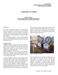
Project Report<br />
2012 MVK160 <strong>Heat</strong> <strong>and</strong> <strong>Mass</strong> Transport<br />
May 7, 2012, Lund, Sweden<br />
<strong>Mass</strong> <strong>and</strong> <strong>Heat</strong> <strong>transfer</strong> <strong>processes</strong> <strong>in</strong> <strong>Solid</strong> <strong>oxide</strong> <strong>fuel</strong> <strong>cell</strong> (<strong>SOFC</strong>)<br />
Chao Yang<br />
Dept. of Energy Sciences, Faculty of Eng<strong>in</strong>eer<strong>in</strong>g,<br />
Lund University, Box 118, 22100 Lund, Sweden<br />
ABSTRACT<br />
<strong>SOFC</strong> is one of the prom<strong>in</strong>ent <strong>fuel</strong> <strong>cell</strong> which<br />
can convert chemical energy of hydrocarbon <strong>fuel</strong><br />
<strong>in</strong>to electrical energy with heat change. This<br />
process <strong>in</strong>cludes mass <strong>transfer</strong> of various reactant<br />
gases (CH 4 , H 2 , H 2 O, CO, CO 2 , O 2 <strong>in</strong> this work)<br />
<strong>and</strong> heat <strong>transfer</strong> between different reaction<br />
<strong>processes</strong> referr<strong>in</strong>g to endothermic methane steam<br />
reform<strong>in</strong>g reactions (MSR) <strong>and</strong> exothermic<br />
electrochemical reactions between different parts of<br />
the <strong>SOFC</strong> components. There is a balance of mass<br />
<strong>and</strong> heat <strong>transfer</strong> between different species,<br />
different reactions <strong>and</strong> also <strong>in</strong> different parts of the<br />
<strong>SOFC</strong>. It is important to evaluate the mass <strong>and</strong> heat<br />
<strong>transfer</strong> <strong>processes</strong> as talked above to research the<br />
reaction mechanism <strong>and</strong> transport process<br />
occurr<strong>in</strong>g <strong>in</strong> <strong>SOFC</strong>, which will be benefit to give an<br />
advice for design <strong>and</strong> optimization of <strong>SOFC</strong>.<br />
1 INTRODUCTION<br />
<strong>Solid</strong> <strong>oxide</strong> <strong>fuel</strong> <strong>cell</strong> (<strong>SOFC</strong>) is one of the<br />
prom<strong>in</strong>ent <strong>fuel</strong> <strong>cell</strong>, it works <strong>in</strong> high temperature<br />
conditions, <strong>SOFC</strong> has a relative higher<br />
performance <strong>and</strong> <strong>fuel</strong> utilization due to its<br />
endothermic <strong>in</strong>ternal reform<strong>in</strong>g occurr<strong>in</strong>g <strong>in</strong> anode<br />
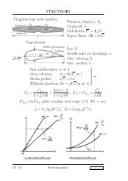
porous layer. Tubular <strong>SOFC</strong> <strong>and</strong> planar <strong>SOFC</strong> are<br />
two basic types of <strong>SOFC</strong>. In this work, planar<br />
<strong>SOFC</strong> is chosen for work as shown <strong>in</strong> Fig.1. The<br />
<strong>SOFC</strong> <strong>cell</strong> <strong>in</strong>cludes porous anode/cathode,<br />
electrolyte, <strong>fuel</strong> <strong>and</strong> air channel, solid connector,<br />
etc. The porous electrode structure is an important<br />
character <strong>in</strong> <strong>SOFC</strong>, gas species can penetrate<br />
through the porous layer from gas channel, then<br />
occurr<strong>in</strong>g reform<strong>in</strong>g <strong>and</strong> electrochemical reactions<br />
near the <strong>in</strong>terface between gas <strong>and</strong> solid phases.<br />
<strong>Mass</strong> <strong>and</strong> energy changes are also occurr<strong>in</strong>g <strong>in</strong> the<br />
<strong>processes</strong> of reactions. High temperature has high<br />
performance <strong>and</strong> more k<strong>in</strong>ds of <strong>fuel</strong> can be used <strong>in</strong><br />
<strong>SOFC</strong>, but high temperature also causes thermal<br />
stress, catalyst degradation (carbon deposition),<br />
materials thermal stability problems, etc. How to<br />
decrease the temperature is a big issue for the<br />
development of <strong>SOFC</strong> [1], evaluate the various<br />
<strong>transfer</strong> <strong>processes</strong> coupled with reaction<br />
mechanism is benefit to achieve the target.<br />
Regard<strong>in</strong>g to the <strong>transfer</strong> <strong>processes</strong> <strong>in</strong> <strong>SOFC</strong>, it<br />
<strong>in</strong>cludes mass, energy, momentum <strong>and</strong> also charge<br />
(electron <strong>and</strong> ion) <strong>transfer</strong>s. The <strong>transfer</strong> <strong>processes</strong><br />
are affected by the reaction occurr<strong>in</strong>g <strong>in</strong> electrode<br />
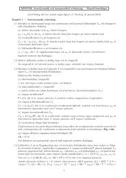
layer (diffusion <strong>and</strong> active layer <strong>in</strong> Fig.2a <strong>and</strong> 2b),<br />
porous characteristics, <strong>fuel</strong> composition, etc.<br />
Referr<strong>in</strong>g to the heat <strong>transfer</strong>, many researchers<br />
assumed an isothermal system <strong>in</strong> their models[2-6],<br />
<strong>in</strong> the other h<strong>and</strong>, many work focus on the heat<br />
<strong>transfer</strong> model<strong>in</strong>g to evaluate the more accuracy<br />
physical <strong>processes</strong> occurr<strong>in</strong>g <strong>in</strong> <strong>SOFC</strong> [7-12]. The<br />
heat <strong>transfer</strong> ma<strong>in</strong>ly refers to the heat generation<br />
due to electrochemical reactions, overpotential<br />
losses <strong>and</strong> joule effects of conductor <strong>and</strong> heat<br />
consumption due to reform<strong>in</strong>g. As mentioned<br />
above, decreas<strong>in</strong>g the temperature is one of the<br />
most important issues <strong>in</strong> the development of <strong>SOFC</strong>,<br />
It is a good approach to <strong>in</strong>crease the thickness of<br />
anode (called anode-supported <strong>SOFC</strong>) <strong>in</strong> order to<br />
reduce the temperature, <strong>and</strong> there is a large amount<br />
of heat <strong>transfer</strong> between anode active layer (with<br />
exothermic electrochemical reactions) <strong>and</strong> anode<br />
support layer (with reform<strong>in</strong>g reactions), it affects<br />
MSR strongly, higher temperature <strong>in</strong>crease the<br />
reaction rate of MSR to improve the performance<br />
of <strong>SOFC</strong>. The conductivities of ion <strong>and</strong> electron<br />
also depend on the temperature distribution. But<br />
too high temperature leads to thermal stress <strong>and</strong><br />
material thermostabilization problem which are the<br />
major reasons of low work<strong>in</strong>g life. Evaluate the<br />
physical <strong>processes</strong> to help underst<strong>and</strong> how it works<br />
<strong>in</strong> energy balance between different components<br />
<strong>and</strong> how to keep balance between temperature<br />
reduction, meanwhile avoid<strong>in</strong>g performance losses.<br />
In recent work, many literatures have focused on<br />
the small scale of function materials <strong>in</strong> porous layer<br />
<strong>and</strong> surface elementary reactions on <strong>and</strong> <strong>in</strong>side<br />
catalyst species [13-17]. In consideration of the<br />
porous structure <strong>and</strong> catalytic elementary reaction<br />
mechanism, more accuracy models have been<br />
developed to evaluate the true physical <strong>processes</strong> <strong>in</strong><br />
<strong>SOFC</strong>.<br />
<strong>Mass</strong> <strong>transfer</strong> <strong>in</strong> <strong>SOFC</strong> is coupl<strong>in</strong>g with other<br />
<strong>transfer</strong>, MSR <strong>and</strong> electrochemical reactions<br />
occurr<strong>in</strong>g <strong>in</strong> anode porous layer are the most
important factors to affect the mass <strong>transfer</strong><br />
<strong>processes</strong>. Due to <strong>in</strong>ternal reform<strong>in</strong>g can occur <strong>in</strong><br />
<strong>SOFC</strong>’s anode, mixture hydrocarbon <strong>fuel</strong><br />
(CH 4 ,H 2 ,H 2 O,CO <strong>and</strong> CO 2 <strong>in</strong> this work) is usually<br />
used, H 2 <strong>and</strong> CO are generated by MSR <strong>and</strong><br />
WGSR, then provide to take part <strong>in</strong> the<br />
electrochemical reactions <strong>in</strong> anode active layer.<br />
H 2 O <strong>and</strong> CO 2 will be produced <strong>in</strong> anode active<br />
layer, amount of H 2 O can be reused by MSR <strong>in</strong><br />
anode which improve the <strong>fuel</strong> usage obviously. In<br />
the other h<strong>and</strong>, O 2 will be consumed <strong>in</strong> the cathode<br />
side. Diffusion of mixture species (especially <strong>in</strong><br />
porous layer) has been worked <strong>in</strong> many literature to<br />
evaluate the physical <strong>processes</strong>. Fick model (FM) is<br />
a simple approach to describe the diffusion between<br />
different gas species, to extend the FM, Stefan-<br />
Maxwell Model (SMM) has been used more <strong>and</strong><br />
more to evaluate the mixture gas diffusion.<br />
Knudsen diffusion is also <strong>in</strong> consideration to fit for<br />
the gas diffusion <strong>in</strong> porous structure. In summary,<br />
FM with Knudsen diffusion (EFM) <strong>and</strong> SMM with<br />
Knudsen diffusion (Dusty-Gas Model DGM) are<br />
most common <strong>in</strong> mixture gas diffusion model <strong>in</strong><br />
<strong>SOFC</strong>. There are both many literatures to use EFM<br />
<strong>and</strong> DGM.<br />
process occurr<strong>in</strong>g <strong>in</strong> the anode layer, <strong>in</strong> anodesupported<br />
planar <strong>SOFC</strong>, MSR reaction occurr<strong>in</strong>g <strong>in</strong><br />
the thick anode can reduce the temperature of<br />
<strong>SOFC</strong>. The heat consumption by MSR reaction is<br />
ma<strong>in</strong>ly provided by the heat production from<br />
electrochemical reactions <strong>and</strong> water-gas shift<br />
reaction(WGSR), exothermic electrochemical<br />
reactions occurr<strong>in</strong>g <strong>in</strong> the active anode layer is the<br />
major heat source. There is a heat <strong>transfer</strong> between<br />
exothermic electrochemical reaction <strong>in</strong> active layer<br />
<strong>and</strong> endothermic reaction <strong>in</strong> diffusion layer.<br />
Regard<strong>in</strong>g to the model describ<strong>in</strong>g the heat <strong>transfer</strong><br />
<strong>processes</strong>, local temperature equilibrium (LTE)<br />
approach is the most common way to be used,<br />
which assume the same temperature for fluid <strong>and</strong><br />
solid materials <strong>in</strong> <strong>SOFC</strong>. Accord<strong>in</strong>gly, local<br />
temperature non-equilibrium (LTNE) approach<br />
which assumes the temperature difference between<br />
solid <strong>and</strong> fluid materials <strong>in</strong> <strong>SOFC</strong> is also used <strong>in</strong><br />
many references. It will be discussed later.<br />
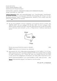
Table I . GEOMETRY OF <strong>SOFC</strong> COMPONENT<br />
Component<br />
Geometry Size (m)<br />
Cell length 20<br />
Cell width (half) 1<br />
Duct width (half) 0.5<br />
Anode support layer thickness 0.48<br />
Anode/Cathode active layer thickness 0.02<br />
Cathode support layer thickness 0.05<br />
Electrolyte layer thickness 0.01<br />
Fig. 1 The sketch of 3D anode-supported <strong>SOFC</strong><br />
<strong>cell</strong><br />
2. HEAT TRANSFER IN <strong>SOFC</strong><br />
<strong>Heat</strong> <strong>transfer</strong> <strong>in</strong> <strong>SOFC</strong> ma<strong>in</strong>ly <strong>in</strong>cludes the<br />
<strong>transfer</strong> <strong>processes</strong> due to the production <strong>and</strong><br />
consumption of reactions, joule, overpotential <strong>and</strong><br />
ohmic effects <strong>in</strong> electronic <strong>and</strong> ion conductor, heat<br />
conductivity, convection <strong>and</strong> heat radiation <strong>in</strong> solid<br />
<strong>and</strong> fluid materials, energy change due to species<br />
diffusion is also <strong>in</strong> consideration <strong>in</strong> some models.<br />
Energy change due to the reactions is the most<br />
important part of heat <strong>transfer</strong> <strong>in</strong> <strong>SOFC</strong>. Methane<br />
steam reform<strong>in</strong>g reaction (MSR) is an endothermic<br />
Fig. 2 The draw<strong>in</strong>g of (a) structure of porous, (b)<br />
mass <strong>and</strong> heat <strong>transfer</strong> <strong>in</strong> <strong>SOFC</strong><br />
2.1 LTE approach model<br />
Assume the same temperature between fluid <strong>and</strong><br />
solid materials <strong>in</strong> <strong>SOFC</strong>, energy balance <strong>in</strong> <strong>SOFC</strong><br />
can been evaluated as:<br />
<br />
n<br />
eff<br />
cp,eff<br />
T<br />
eff cp,eff UT = ( keff T mh<br />
i i<br />
) S<br />
(1)<br />
<br />
T<br />
<br />
i1<br />
As shown above, the energy balance equation<br />
<strong>in</strong>cludes unsteady term, convection term, diffusion<br />
term <strong>and</strong> source term. The first two terms on the<br />
right-h<strong>and</strong> side of equation represent energy<br />
<strong>transfer</strong> due to conduction <strong>and</strong> species diffusion,<br />
respectively. And k eff , c p,eff represents effective
conductivity <strong>and</strong> specific heat capacity which equal<br />
to:<br />
keff <br />
k<br />
f<br />
(1 <br />
) ks<br />
(2)<br />
cp, eff<br />
cp, f<br />
(1 <br />
) cp,<br />
s<br />
(3)<br />
where ε is the porosity.<br />
S T <strong>in</strong> equation (1) is source term which can be<br />
represented as:<br />
2<br />
ST hreact Ran , cat<br />
an,<br />
cat<br />
I Rohm<br />
(4)<br />
where R an,cat η an,cat is heat change due to<br />
overpotential by active current, I 2 R ohm is joule heat<br />
production due to ohmic effects, h react is the<br />
enthalpy change caused by reactions, MSR, WGSR<br />
<strong>and</strong> electrochemical reactions which should be <strong>in</strong><br />
consideration, then h react can be represented as:<br />
<br />
S Rh<br />
T i reaction,<br />
i<br />
i<br />
(5)<br />
where R i are reaction rates of MSR, MGSR <strong>and</strong><br />
electrochemical reactions, i is the reaction <strong>in</strong>dex,<br />
Δh reaction,i are enthalpy changes of those reactions.<br />
2.2 LTNE approach model<br />
In consideration of the temperature distribution<br />
between solid <strong>and</strong> fluid phase, the temperature<br />
distribution can be calculated separately for the gas<br />
<strong>and</strong> solid phase as shown below:<br />
( ks<br />
Ts)<br />
Q<br />
s<br />
(6)<br />
( kg Tg)<br />
Qg g cp,<br />
g<br />
uT g<br />
(7)<br />
where k s <strong>and</strong> k g are conductivity of solid <strong>and</strong> gas<br />
phase, Q s <strong>and</strong> Q g are source terms <strong>in</strong> solid <strong>and</strong> gas<br />
phase. It should be noted that, the source term Q s <strong>in</strong><br />
solid phase <strong>in</strong>cludes heat <strong>transfer</strong> between two<br />
phase, heat production of electrochemical reaction,<br />
ohmic effects <strong>and</strong> overpotential losses <strong>in</strong> active<br />
layer. Q g <strong>in</strong> gas phase <strong>in</strong>cludes heat <strong>transfer</strong><br />
between two phase <strong>and</strong> enthalpy changes of MSR<br />
<strong>and</strong> WGSR. The heat source is similar with LTE<br />
approach model discussed above. But there is a<br />
heat <strong>transfer</strong> between solid <strong>and</strong> gas phase which<br />
can be evaluated by:<br />
Qg hv( Tg Ts) SAhs, g,<br />
por<br />
( Tg Ts)<br />
(8)<br />
where h s,g,por is the heat <strong>transfer</strong> coefficient which<br />
can be evaluated <strong>in</strong> [18]. SA is the surface area ratio<br />
which means the surface area per volume.<br />
2.3 Radiation effects<br />
Due to the high temperature of <strong>SOFC</strong> (800-<br />
1100K), thermal radiation has been <strong>in</strong> evaluated <strong>in</strong><br />
many work, In general, heat radiation <strong>in</strong> <strong>SOFC</strong> is<br />
between the surface of gas <strong>and</strong> solid phase, as<br />
shown below:<br />
' 4<br />
qnet Ak<br />
s<br />
( gTg gT<br />
4 s<br />
) (9)<br />
where A s is the active surface area, ε g is the<br />
emissivity <strong>and</strong> the α g is absorptivity.<br />
2.4 Enthalpy change <strong>in</strong> energy equation<br />
As mentioned above, the energy change of MSR<br />
<strong>and</strong> WGSR can be evaluated by enthalpy change of<br />
global way as shown below:<br />
CH<br />
4+H2O CO+ 3H2 ΔH (1000 K)<br />
= 226 kJ/mol (10)<br />
COH2O CO2 H2 H ( 1000K) 35 kJ / mol (11)<br />
the electrochemical reaction can be formulated<br />
globally as well:<br />
2<br />
H<br />
2<br />
O <br />
<br />
H2O2e H( 1000K) 248 kJ / mol (12)<br />
More <strong>and</strong> more work has been done <strong>in</strong> the<br />
elementary surface reactions mechanism <strong>in</strong> Ni/YSZ<br />
materials, It describes the elementary reactions of<br />
adsorption, desorption <strong>and</strong> surface reaction <strong>in</strong><br />
catalyst, there are multi-step mechanisms to<br />
describe the methane steam occurr<strong>in</strong>g reform<strong>in</strong>g<br />
reaction <strong>and</strong> electrochemical reactions <strong>in</strong> the<br />
Ni/YSZ anode materials respectively.<br />
Table II. HETEROGENEOUS REACTION MECHANISM<br />
FOR METHANE REFORMING REACTIONS ON NI/YSZ<br />
Reaction<br />
Reaction<br />
1. H 2 +Ni s +Ni s →H s +H s 22. CO2s+Nis→Os+COs<br />
2. O 2 +Ni s +Ni s →O s +O s 23. HCO s +Ni s →Hs+CO s<br />
3. Nis+CH4→CH4s 24. H s +CO s →HCO s +Ni s<br />
4. H2O+Nis→H2Os 25. HCO s +Ni s →CH s +O s<br />
5. CO2+Nis→CO2s 26. CH s +O s →HCO s +Ni s<br />
6. CO+Nis→COs 27. CH 4s +Ni s →CH 3s +H s<br />
7. Hs+Hs→H2+Nis+Nis 28. CH 3s +H s →CH 4s +Ni s<br />
8. Os+Os→O2+Nis+Nis 29. CH 3s +Ni s →CH 2s +H s<br />
9. CH4s→Nis+CH4 30. CH 2s +H s →CH 3s +Ni s<br />
10. H2Os→H2O+Nis 31. CH 2s +Ni s →CH s +H s<br />
11. CO2s→CO2+Nis 32. CH s +H s →CH 2s +Ni s<br />
12. COs→CO+Nis 33. CH s +Ni s →C s +H s<br />
13. Os+Hs→OHs+Nis 34. C s +H s →CH s +Ni s<br />
14. OHs+Nis→Os+Hs 35. O s +CH 4s →CH 3s +OH s<br />
15. OHs+Hs→H2Os+Nis 36. OH s +CH3 s →O s +CH 4s<br />
16. H2Os+Nis→OHs+Hs 37. O s +CH3 s →CH2 s +OH s<br />
17. OHs+OHs→Os+H2Os 38. OH s +CH2 s →CH3 s +O s<br />
18. Os+H2Os→OHs+OHs 39. O s +CH 2s →CH s +OH s<br />
19. Os+Cs→COs+Nis 40. OH s +CH s →CH 2s +O s<br />
20. COs+Nis→Os+Cs 41. O s +CH s →C s +OH s<br />
21. Os+COs→CO2s+Nis 42. C s +OH s →O s +CH s<br />
For example, there is a 42-step elementary<br />
reactions mechanism <strong>in</strong>clud<strong>in</strong>g several gases <strong>and</strong><br />
surface species participat<strong>in</strong>g <strong>in</strong> the elementary<br />
reaction <strong>processes</strong> as shown <strong>in</strong> Table II, <strong>and</strong> the<br />
enthalpy changes of each species which can be<br />
used to calculate the heat change <strong>in</strong> each reaction<br />
has also been evaluated <strong>in</strong> Table III.<br />
Table III. ENTHALPIES OF SPECIES IN NI/YSZ<br />
MATERIALS IN 973K<br />
Species<br />
Molar<br />
Enthalpies<br />
J/mol Species<br />
Molar<br />
Enthalpies<br />
J/mol Species<br />
Molar<br />
Enthalpies<br />
J/mol<br />
H2 1,987E+04 H2Os -2,816E+05 CO2s -3,915E+05<br />
H2O 2,169E+05 Hs -3,274E+04 HCOs -1,136E+05<br />
O2 2,176E+04 OHs -1,997E+05 CH4s -8,022E+04<br />
CH4 3,860E+04 COs -2,051E+05 CH3s -5,135E+04
CO 8,974E+04 Cs -3,275E+04 CH2s 2,607E+04<br />
CO2 3,616E+05 Os -2,287E+05 CHs 7,675E+04<br />
2.5 Further improvement discussion<br />
More <strong>and</strong> more work has been focused on the<br />
small scale of <strong>SOFC</strong> <strong>in</strong>volv<strong>in</strong>g the meso-scale <strong>and</strong><br />
micro-scale models of porous electrode <strong>and</strong><br />
electrolyte, elementary reactions on catalytic<br />
surface species, etc. It has improved the heat<br />
<strong>transfer</strong> model more accurate <strong>and</strong> reasonable <strong>in</strong><br />
some aspects.<br />
2.5.1 Effect heat conductivity<br />
More <strong>and</strong> more work has been focused on the<br />
heat analysis <strong>and</strong> model development based on the<br />
smaller scale of porous electrode structure. As<br />
mentioned before, the heat conductivity <strong>in</strong> porous<br />
layer can been evaluated as equation (13), but it can<br />
not def<strong>in</strong>e the different solid connect materials (Ni<br />
<strong>and</strong> YSZ) <strong>in</strong> porous layer. Due to low velocity of<br />
gas <strong>transfer</strong> <strong>in</strong> porous layer, convection can be<br />
omitted <strong>in</strong> comparison with heat conduct <strong>in</strong> some<br />
degree, <strong>and</strong> conduct through solid structure<br />
dom<strong>in</strong>ates the heat <strong>transfer</strong> process. Evaluate the<br />
conductivity of Ni <strong>and</strong> YSZ separately is necessary<br />
to improve the accuracy of heat <strong>transfer</strong> <strong>and</strong><br />
temperature distribution, as shown <strong>in</strong> equation (13):<br />
k 1<br />
<br />
eff<br />
( ) k V s,<br />
i<br />
<br />
eff<br />
i <br />
(13)<br />
where ε is porosity, τ is tortuosity, k s,i is<br />
conductivity of Ni or YSZ, <strong>and</strong> V eff is volume<br />
fraction of each species <strong>in</strong> solid part. Table IV is<br />
porous properties <strong>in</strong> <strong>SOFC</strong>.<br />
Table IV. POROUS PROPERTIES IN <strong>SOFC</strong><br />
Anode Electrolyte Cathode<br />
ε 0.4 0 0.3<br />
τ 10 None 10<br />
Veff YSZ:0.6, Ni:0.4 YSZ:1 YSZ:0.6, Ni:0.4<br />
2.5.3 <strong>Heat</strong> <strong>transfer</strong> <strong>in</strong> rarefied gases region.<br />
As mentioned above, the scale of signal <strong>SOFC</strong><br />
<strong>cell</strong> is on mm order, the component (channel,<br />
electrode, electrolyte, etc.) of <strong>cell</strong> unit is less than<br />
mm order, <strong>and</strong> the function layer (active layer,<br />
porous pore, etc.) is under μm order. In the micro<br />
structure <strong>in</strong> <strong>SOFC</strong>, cont<strong>in</strong>uum model is not<br />
adequately to describe the low pressure or low<br />
density <strong>in</strong> small scales. It is supposed to develop a<br />
new approach to characterize the <strong>transfer</strong> <strong>processes</strong><br />
<strong>in</strong> smaller scales. Compare with conventional<br />
approach used <strong>in</strong> cont<strong>in</strong>uum model, k<strong>in</strong>etic gas<br />
theory with important parameters (wavelength of<br />
the molecular, mean velocity, etc.) is a good tool to<br />
evaluate the conditions. There is a reasonable<br />
approach to evaluate the flow type of boundary<br />
layer between solid surface <strong>and</strong> gas flow <strong>in</strong> <strong>SOFC</strong>.<br />
As shown <strong>in</strong> equation (16)-(17), Knudsen number<br />
represent the ratio of free mean path wavelength λ<br />
of the molecule <strong>and</strong> characteristic dimension L, for<br />
boundary layer <strong>in</strong> <strong>SOFC</strong>, characteristic dimension<br />
is thickness of boundary layer δ.<br />
1 r<br />
Ma<br />
Kn <br />
/ L <br />
0.499 8 Re<br />
(16)<br />
Ma<br />
Kn <br />
Re<br />
(17)<br />
In summary, the flow can be divided <strong>in</strong>to<br />
different regimes depend<strong>in</strong>g on the magnitude of<br />
the Knudsen number, <strong>and</strong> there are different<br />
methods for different flow regimes, as shown<br />
below.<br />
Table V. GENERAL FLOW REGIMES DIVIDED BY<br />
KNUDSEN NUMBER<br />
Flow<br />
regimes<br />
Important<br />
parameter<br />
for<br />
validation<br />
Characteristic<br />
conditions<br />
Methods<br />
2.5.2 Anisotropic heat <strong>transfer</strong><br />
Regard<strong>in</strong>g to the particle structure of porous<br />
layer <strong>in</strong> smaller scale as shown <strong>in</strong> Fig.2a, heat<br />
<strong>transfer</strong> should be <strong>in</strong> consideration of anisotropic<br />
way. Compare with isotropic materials, the thermal<br />
conductivity <strong>in</strong> anisotropic materials is assumed to<br />
vary with the directions. Omit the effect of<br />
convection <strong>and</strong> heat <strong>transfer</strong> by diffusion, energy<br />
equation for anisotropic materials can be evaluated<br />
as:<br />
2 2 2 2<br />
eff<br />
cp,eff<br />
T T T T T<br />
kxx k 2 xy<br />
kxz kyx<br />
<br />
x xy xz yx<br />
<br />
2 2 2 2 2<br />
T T T T T<br />
kyy k 2 yz<br />
kzx kzy kzz<br />
S<br />
2 T<br />
y yz zx zy z<br />
(14)<br />
where k ij is the anisotropic conductivity <strong>in</strong> different<br />
directions, it should be noted that k ij =k ji then the<br />
equation can be simplified as:<br />
2 2 2<br />
eff<br />
cp,eff<br />
T T T T<br />
kxx k 2 yy<br />
k<br />
2 zz 2<br />
<br />
x y z<br />
2 2 2<br />
T T T<br />
2kxy 2kyz 2kxz ST<br />
xy yz zy<br />
(15)<br />
Cont<strong>in</strong>uum<br />
flow<br />
Ma Re <<br />
0.01<br />
Slip flow 0.01<<br />
Ma Re <<br />
0.1<br />
Transition<br />
flow<br />
Ma Re ><br />
0.1 <strong>and</strong><br />
Ma/Re
Free<br />
molecular<br />
flow<br />
(Knudsen<br />
flow)<br />
Ma/Re>10<br />
Molecular hit the<br />
solid surface much<br />
more than<br />
<strong>in</strong>termolecular<br />
collisions, the<br />
boundary flow<br />
depends on the<br />
<strong>in</strong>teraction between<br />
fluid molecular <strong>and</strong><br />
solid surface.<br />
Use k<strong>in</strong>etic<br />
gas theory<br />
k j can been expressed as Arrhenius expression as<br />
below [20]:<br />
Ks<br />
E<br />
j<br />
aj <br />
kj<br />
kj k <br />
k<br />
jAT<br />
j<br />
exp( ) k<br />
exp( ) <br />
RT k1<br />
RT (25)<br />
where A j <strong>and</strong> E aj are Arrhenius parameters, μ kj <strong>and</strong><br />
ε kj the parameters model<strong>in</strong>g the coverage<br />
dependence on the rate constants, θ k is the surface<br />
coverage.<br />
It should be noted that, this theory is also<br />
adequately for momentum <strong>and</strong> mass <strong>transfer</strong>.<br />
3 MASS TRANSFER IN <strong>SOFC</strong><br />
<strong>Mass</strong> <strong>transfer</strong> <strong>in</strong> <strong>SOFC</strong> is very important for the<br />
reactions <strong>and</strong> performance of <strong>fuel</strong> <strong>cell</strong>. <strong>Mass</strong><br />
<strong>transfer</strong> <strong>in</strong> <strong>SOFC</strong> ma<strong>in</strong>ly refers to diffusion of the<br />
multi-component gas species <strong>and</strong> transport <strong>in</strong><br />
porous layer. <strong>Mass</strong> balance equation has been<br />
shown below:<br />
( eff U Yi ) ( Di,<br />
eff<br />
Y i<br />
) S<br />
(18)<br />
g , i<br />
where D i,eff is mass diffusion coefficient, Y i is mass<br />
fraction of species i <strong>and</strong> S g,i is mass source term of<br />
species i. And ρ eff is effective density of multicomponent<br />
gas species which can be expressed as:<br />
<br />
X <br />
eff i i<br />
f i<br />
(19)<br />
X i is molar fraction of gas species i.<br />
3.1 Source term<br />
Accord<strong>in</strong>g to the source term, it depends on the<br />
reaction mechanism. In global reaction mechanism<br />
as discussed <strong>in</strong> 2.4, source term of species i <strong>in</strong><br />
reform<strong>in</strong>g <strong>and</strong> electrochemical reactions can be<br />
evaluated as:<br />
Sg , i<br />
( mRr nRs)<br />
M<br />
i<br />
(20)<br />
Iact<br />
Sele,<br />
i<br />
TPB Mi<br />
nF<br />
(21)<br />
where R r <strong>and</strong> R s are reaction rate of MSR <strong>and</strong><br />
WGSR, I act is active current density, <strong>and</strong> TPB is<br />
three phase boundary area per volume for<br />
electrochemical reaction.<br />
In surface elementary reaction mechanism of<br />
methane on Ni/YSZ anode as discussed <strong>in</strong> Table II,<br />
reaction rate of each gas species should be<br />
expressed as [19]:<br />
Kr<br />
KgKs<br />
<br />
R <br />
k X<br />
gi ,<br />
ij j i<br />
j1 i1<br />
(22)<br />
where k j is the reaction constant, K r , K g , K s<br />
represent the number of the total reactions, gas <strong>and</strong><br />
surface-phase species, respectively, υ ij <strong>and</strong> υ ’ ij the<br />
stochiometric coefficients of products <strong>and</strong> reactants.<br />
[X i ] is gas species concentration:<br />
X<br />
i<br />
p<br />
3<br />
X<br />
( /<br />
i<br />
<br />
mol cm )<br />
6<br />
RT<br />
g<br />
10<br />
(23)<br />
while the surface-phase species concentration is<br />
calculated by :<br />
2<br />
X<br />
i itot ( mol / cm )<br />
(24)<br />
Γ tot is the total surface site density <strong>in</strong>clud<strong>in</strong>g open<br />
catalyst surface specie Ni s .<br />
'<br />
ij<br />
<br />
3.2 Diffusion coefficient<br />
As mentioned above, diffusion of mass can be<br />
evaluated by EFM which can be calculated D i,eff as:<br />
Digm<br />
,<br />
Dik<br />
,<br />
Dieff<br />
,<br />
<br />
Digm<br />
,<br />
Dik<br />
,<br />
(26)<br />
where ε is porosity <strong>and</strong> τ is tortuosity of porous<br />
materials, D i,gm is the diffusion of multi-component<br />
gas species, which can be expressed as [21]:<br />
1<br />
Yi<br />
Digm<br />
,<br />
<br />
Y<br />
<br />
i<br />
i<br />
j Di,<br />
j<br />
(27)<br />
where D i,j are the b<strong>in</strong>ary diffusion coefficients of<br />
gas-phase species i, as shown <strong>in</strong> Table VI.<br />
Table VI. BINARY DIFFUSIVITY OF THE ITH GAS-<br />
PHASE SPECIES AT T=1123.2K, P=1.013 BAR [22]<br />
i/j D ij (m2/s) i/j D ij (m2/s)<br />
CH 4 /CO 3.47e-05 CO/ H 2 11.92e-05<br />
CH 4 / H 2 O 4.30e-05 CO/ CO 2 2.59e-05<br />
CH 4 / H 2 11.04e-05 H 2 O/ H 2 14.10e-05<br />
CH 4 /CO 2 2.88e-05 H 2 O/ CO 2 3.38e-05<br />
CO/ H 2 O 4.15e-05 H 2 / CO 2 10.23e-05<br />
The diffusion coefficients of gas-phase species i<br />
<strong>in</strong> the porous layer are controlled by the pore size<br />
<strong>and</strong> the free-path of the diffusion gas molecules. In<br />
this work, it is assumed that the mean free-path of<br />
the molecules is bigger than the pore size, which<br />
means that the collisions between the molecules<br />
<strong>and</strong> the walls are more often than the collisions<br />
between themselves. Then, Knudsen diffusion is<br />
evaluated as follows:<br />
2 2 8RT<br />
Dik ,<br />
revi re<br />
3 3 M<br />
i<br />
(28)<br />
where r e is the effective radius <strong>and</strong> ν i is the average<br />
molecular speed of species i.<br />
But SMM has been used <strong>in</strong> many literatures [23-<br />
25]. It is generally agreed that DGM is superior to<br />
EFM to predict the fluxes <strong>in</strong>side porous materials<br />
[26]. The model can be evaluated by [27]:<br />
( effU Yi ) ( Jk ) S<br />
(29)<br />
g,<br />
i<br />
where J k equal to<br />
<br />
DGM<br />
Kg<br />
Kg Dij<br />
X<br />
DGM<br />
j <br />
Ji Mi Dij X <br />
<br />
(30)<br />
<br />
<br />
j <br />
<br />
p<br />
e<br />
j1 j1<br />
D <br />
j<strong>in</strong> ,<br />
<br />
<br />
<br />
<br />
<br />
<br />
where D DGM kl are def<strong>in</strong>ed as the matrix of DGM<br />
diffusion coefficients <strong>and</strong> can be represented as a<br />
matrix <strong>in</strong>verse:<br />
D<br />
DGM<br />
ij<br />
<br />
1<br />
H <br />
where the elements of H matrix are<br />
(31)
1 X <br />
l<br />
X<br />
i<br />
hij <br />
<br />
ij<br />
(<br />
ij<br />
1)<br />
e<br />
<br />
e<br />
e<br />
D l <br />
j,<br />
<strong>in</strong><br />
D <br />
<br />
<br />
il Dil<br />
(32)<br />
D i,j <strong>and</strong> D i , k are the effective b<strong>in</strong>ary diffusion<br />
coefficient <strong>and</strong> effective Knudsen diffusion<br />
coefficient which have been given above.<br />
4 SIMULATION RESUTLS AND<br />
DISCUSSION<br />
In this work, a <strong>SOFC</strong> model (discussed <strong>in</strong> Table<br />
1) <strong>in</strong>volved LTE energy model (equations (1)-(5))<br />
with global reaction mechanisms referr<strong>in</strong>g to<br />
equations (10)-(12) has been simulated by<br />
Ansys/Fluent 12.1 with Fuel Cell Module issued by<br />
Fluent Inc. to show the temperature <strong>and</strong> gas species<br />
distribution <strong>in</strong> order to evaluate the heat <strong>and</strong> mass<br />
<strong>transfer</strong>. It should be noted that, the CFD model is<br />
also <strong>in</strong>cludes momentum <strong>transfer</strong> besides heat <strong>and</strong><br />
mass <strong>transfer</strong> but not be discussed <strong>in</strong> this paper.<br />
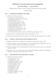
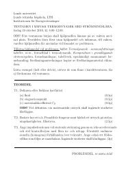
Fig. 4 (a) Distribution of H 2 (molar fraction) <strong>in</strong><br />
anode, (b) H 2 along ma<strong>in</strong> flow direction at<br />
symmetric side<br />
Regard<strong>in</strong>g to the mass distribution, it <strong>in</strong>cludes<br />
the hydrocarbon <strong>fuel</strong> <strong>in</strong> anode side <strong>and</strong> oxidant (O 2 )<br />
<strong>in</strong> cathode side. H 2 distribution is shown <strong>in</strong> Fig 4a<br />
<strong>and</strong> b, X H2 <strong>in</strong> porous layer is big near the <strong>in</strong>let<br />
region, <strong>and</strong> decreases along the y direction, that is<br />
because of the comb<strong>in</strong>ed reform<strong>in</strong>g <strong>and</strong><br />
electrochemical reactions. MSR <strong>and</strong> WGSR<br />
produce large amount of H 2 especially near the<br />
<strong>in</strong>let region, <strong>and</strong> H 2 goes through the porous layer<br />
then be consumed by electrochemical reaction at<br />
TPB near the electrolyte. The H 2 distribution along<br />
z direction is affected by channel near <strong>in</strong>let <strong>and</strong> by<br />
electrochemical reaction near outlet, it is <strong>in</strong> keep<br />
with the reform<strong>in</strong>g rate <strong>and</strong> H 2 drop.<br />
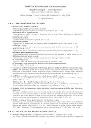
Fig. 3 (a) Temperature distribution <strong>in</strong> half-<strong>cell</strong>, (b)<br />
Temperature distribution <strong>in</strong> sectional cross near<br />
outlet<br />
Accord<strong>in</strong>g to Fig.3a, It shows the temperature<br />
distribution affected by the reform<strong>in</strong>g <strong>and</strong><br />
electrochemical reactions. As mentioned above,<br />
there is a heat balance between endothermic RSM<br />
with exothermic electrochemical reactions, <strong>and</strong> a<br />
higher temperature appears <strong>in</strong> active layer near<br />
electrolyte. Lower temperature exits <strong>in</strong> <strong>in</strong>let side<br />
which means bigger reaction rate of reform<strong>in</strong>g<br />
consum<strong>in</strong>g more heat, it is because the higher <strong>fuel</strong><br />
concentration near <strong>in</strong>let improves MSR. As shown<br />
<strong>in</strong> Fig. 3b, the temperature of gas channel is lower<br />
than other parts.
Fig. 5 (a) Distribution of CH 4 <strong>in</strong> anode, (b) CH 4<br />
along ma<strong>in</strong> flow direction at symmetric side<br />
Fig. 6 (a) Distribution of O 2 <strong>in</strong> cathode, (b)O 2<br />
along ma<strong>in</strong> flow direction at symmetric side<br />
As shown <strong>in</strong> Fig.5a <strong>and</strong> b, CH 4 decrease along<br />
all directions because of consumption by reform<strong>in</strong>g<br />
<strong>in</strong> anode porous layer, X CH4 is about 11% to 17%,<br />
which means the usage of CH 4 is only up to 45%.<br />
The only reactant <strong>in</strong> the cathode side O 2 also<br />
decreases as shown <strong>in</strong> Fig.6a <strong>and</strong> b. It should be<br />
noted that, the concentration near outlet decrease<br />
apparently, even below 1% <strong>in</strong> some part along z<br />
direction, it means too much O 2 has been used <strong>in</strong><br />
the active layer <strong>and</strong> lower concentration will cause<br />
big concentration potential losses.<br />
In Fig.7, the distribution of H 2 , H 2 O, CH 4 , CO,<br />
CO 2 <strong>and</strong> O 2 have been presented along ma<strong>in</strong> flow<br />
direction of anode <strong>and</strong> cathode <strong>in</strong> active layer (<strong>in</strong><br />
Fig.7a) <strong>and</strong> diffusion layer (<strong>in</strong> Fig.7b). H 2 O <strong>and</strong><br />
CO 2 are ma<strong>in</strong> production <strong>in</strong> anode side. It should<br />
be noted that, as reactant of MSR <strong>and</strong> WGSR, H 2 O<br />
is still <strong>in</strong>creas<strong>in</strong>g, even though the electrochemical<br />
reaction rate is much smaller than reform<strong>in</strong>g. The<br />
MSR is still <strong>in</strong>sufficient, maybe due to <strong>fuel</strong><br />
concentration, porous diffusion, catalyst activity,<br />
etc. CH 4 <strong>and</strong> H 2 are ma<strong>in</strong> reactants at anode side<br />
<strong>and</strong> O 2 is the only reactant at cathode side,<br />
respectively. X H2 is big near <strong>in</strong>let because strong<br />
reform<strong>in</strong>g releases large amount of H 2 , but it<br />
decreases apparently. CO is generated by MSR <strong>and</strong><br />
consumed by WGSR <strong>and</strong> electrochemical reaction,<br />
its concentration becomes small, especially near the<br />
outlet where the rate of reform<strong>in</strong>g is smallest.<br />
Compar<strong>in</strong>g with the distribution between two<br />
figures, it is found that less H 2 , CO <strong>and</strong> more H 2 O,<br />
CO 2 exit <strong>in</strong> active layer (Fig.7a) due to<br />
electrochemical reactions occurs <strong>in</strong> active layer.<br />
Fig. 7 Averaged molar fraction of <strong>fuel</strong> <strong>and</strong> O 2<br />
along ma<strong>in</strong> flow direction <strong>in</strong> (a) active layer (plane<br />
y=1.385mm <strong>in</strong> anode <strong>and</strong> y=1.365mm <strong>in</strong> cathode)<br />
(b) diffusion layer (plane y=1.65mm <strong>in</strong> anode <strong>and</strong><br />
y=1.33mm <strong>in</strong> cathode)<br />
CONLUSION<br />
In this work, the heat <strong>and</strong> mass <strong>transfer</strong> <strong>in</strong> <strong>SOFC</strong><br />
has been discussed. The heat process is based on<br />
the exothermic <strong>and</strong> endothermic reactions<br />
occurr<strong>in</strong>g <strong>in</strong> the active <strong>and</strong> diffusion layer <strong>in</strong> <strong>SOFC</strong>,<br />
overpontential losses <strong>and</strong> ohimc effect are also<br />
<strong>in</strong>cluded. <strong>Heat</strong> <strong>transfer</strong> between solid <strong>and</strong> gas phase<br />
<strong>and</strong> thermal radiation are supposed to be <strong>in</strong><br />
consideration <strong>in</strong> the future work. <strong>Mass</strong> <strong>transfer</strong><br />
model referr<strong>in</strong>g to multi-component <strong>fuel</strong> <strong>and</strong> air<br />
has been developed, there are EFM <strong>and</strong> SMM to<br />
evaluate the mass <strong>transfer</strong> <strong>processes</strong> <strong>in</strong> the porous<br />
layer, mass <strong>transfer</strong> is coupled with heat <strong>transfer</strong><br />
due to the reactions which consume <strong>and</strong> produce<br />
the mass <strong>and</strong> heat simultaneously. The further<br />
discussion should be taken <strong>in</strong> the smaller scale, the<br />
mechanism of heat <strong>and</strong> mass <strong>transfer</strong> will be<br />
different <strong>in</strong> the smaller scale model, improvements<br />
for the method to evaluate the micro-scale <strong>transfer</strong><br />
<strong>processes</strong> (such as gas species <strong>and</strong> heat <strong>transfer</strong> <strong>in</strong><br />
the pore structure, or <strong>in</strong> the catalyst surface, etc. )<br />
are supposed to be develop <strong>in</strong> the future work.<br />
REFERENCE<br />
[1] D. Wachsman, Kang Taek Lee, 2011,<br />
“Lower<strong>in</strong>g the Temperature of <strong>Solid</strong> Oxide<br />
Fuel Cells”, Science 18 November, pp.<br />
935-939.<br />
[2] J<strong>in</strong> X, Xue X. 2010, “Mathematical<br />
model<strong>in</strong>g analysis of regenerative solid<br />
<strong>oxide</strong> <strong>fuel</strong> <strong>cell</strong>s <strong>in</strong> swithch<strong>in</strong>g mode<br />
conditions”. Journal of Power Sources<br />
195, pp. 6652-6658
[3] Zu H, Kee Rj. 2003, “A general<br />
mathematical model for analyz<strong>in</strong>g the<br />
performance of <strong>fuel</strong>-<strong>cell</strong> membraneelectrode<br />
assemblies” Journal of Power<br />
Sources, 117, pp.61-74.<br />
[4] Suwanwarangkul R, Croiset E, Pritzker<br />
MD, 2006, “Mechanistic model<strong>in</strong>g of a<br />
cathode-supported tubular solid <strong>oxide</strong> <strong>fuel</strong><br />
<strong>cell</strong>” Journal of Power Sources, 154, pp.<br />
74-85.<br />
[5] Lehnert W, Meus<strong>in</strong>ger J, Thom F. 2000,<br />
“Modell<strong>in</strong>g of gas transport phenomena <strong>in</strong><br />
<strong>SOFC</strong> anodes” Journal of Power Sources,<br />
87, pp. 57-63.<br />
[6] Xie Y, Xue X. 2009, “Transient model<strong>in</strong>g<br />
of anode-supported solid <strong>oxide</strong> <strong>fuel</strong> <strong>cell</strong>s”<br />
International Journal of Hydrogen Energy,<br />
34, pp. 6682-6691.<br />
[7] B. Sundén <strong>and</strong> J. Yuan 2010,<br />
“Development of Multi-scale Models for<br />
Transport Processes Involv<strong>in</strong>g Catalytic<br />
Reactions <strong>in</strong> <strong>SOFC</strong>s,” Int. J. Micro-Nano<br />
Scale Transport, Vol.1, No.1, pp. 37-42.<br />
[8] BA Haberman, JB Young, 2004 “Threedimensional<br />
Simulation of Chemically<br />
Rreact<strong>in</strong>g Gas Flows <strong>in</strong> the Porous<br />
Support Structure of an Integrated-planar<br />
<strong>Solid</strong> Oxide Fuel Cell,” Int.J. <strong>Heat</strong> <strong>Mass</strong><br />
Tranfer, 47, pp. 3617-3629.<br />
[9] A. Aguiar, C.S. Adjiman, <strong>and</strong> N.P.<br />
Br<strong>and</strong>on. 2004 “Anode-supported<br />
Intermediate Temperature Direct Internal<br />
Reform<strong>in</strong>g <strong>Solid</strong> Fuel Cell, I: Modelbased<br />
Steady-state Performance”. J. Power<br />
Sources 138, pp. 120-136,.<br />
[10] H. Yakabe, M. Hish<strong>in</strong>uma, M. Uratani, Y.<br />
Matsuzaki <strong>and</strong> J. Yasuda, 2000<br />
“Evaluation <strong>and</strong> Model<strong>in</strong>g of Performance<br />
of Anode-supported <strong>Solid</strong> Oxide Fuel<br />
Cell,” J. Power sources 86, pp. 423-431.<br />
[11] J. Yuan <strong>and</strong> B. Sunden, 2006 “Analysis of<br />
Chemically React<strong>in</strong>g Transport<br />
Phenomena <strong>in</strong> an Anode Duct of<br />
Intermediate Temperature <strong>SOFC</strong>s,” ASME<br />
J.Fuel Cell Sci., Tech. <strong>and</strong> Engn., 2, pp.<br />
89-98.<br />
[12] J. Yuan, Y. Huang, B. Sundén <strong>and</strong> W.G.<br />
Wang, 2009, “CFD Approach to Analyze<br />
Parameter Effects on Chemical-React<strong>in</strong>g<br />
Transport Phenomena <strong>in</strong> <strong>SOFC</strong> Anodes”,<br />
<strong>Heat</strong> <strong>and</strong> <strong>Mass</strong> Transfer, 45, pp. 471-484.<br />
[13] U. Doraswarmi, P. Shear<strong>in</strong>g, N.<br />
Droushiotis, K. Li, N.P. Br<strong>and</strong>on, G.H.<br />
Kelsall, 2011, “Modell<strong>in</strong>g the effects of<br />
measured anode triple-phase boundary<br />
densities on the performance of microtubular<br />
hollow fiber <strong>SOFC</strong>s” <strong>Solid</strong> State<br />
Ionics, 192, pp. 494-500.<br />
[14] K.N. Grew, A.S. Joshi, A.A. Peracchio,<br />
W.K.S. Chiu, 2010, “Pore-scale<br />
<strong>in</strong>vestigation of mass transport <strong>and</strong><br />
electrochemistry <strong>in</strong> a solid <strong>oxide</strong> <strong>fuel</strong> <strong>cell</strong><br />
anode” 195, pp. 2331-2345.<br />
[15] V.M. Janardhanan, O. Deutschmann,<br />
2006, “CFD analysis of a solid <strong>oxide</strong> <strong>fuel</strong><br />
<strong>cell</strong> with <strong>in</strong>ternal reform<strong>in</strong>g coupled<br />
<strong>in</strong>teractions of transport, heterogeneous<br />
catalysis <strong>and</strong> electrochemical <strong>processes</strong>”<br />
162, pp. 1192-1202.<br />
[16] Sangho S., J<strong>in</strong> H.N., Dong H. J. Charn J.<br />
K. 2010, “A micro macroscale model for<br />
<strong>in</strong>termediate temperature solid <strong>oxide</strong> <strong>fuel</strong><br />
<strong>cell</strong>s with prescribed fully-developed axial<br />
velocity profiles <strong>in</strong> gas channels”<br />
International Journal of Hydrogen Energy<br />
35, pp. 11890-11907.<br />
[17] Zhang, Y., Xia C., Ni M.<br />
2012, ”Simulation of s<strong>in</strong>ter<strong>in</strong>g k<strong>in</strong>etics<br />
<strong>and</strong> microstructure evolution of composite<br />
solid <strong>oxide</strong> <strong>fuel</strong> <strong>cell</strong>s electrodes”,<br />
International journal of hydrogen energy<br />
37, pp. 3392-3402.<br />
[18] Damm D.L., Fedorov A.G., Local Thermal<br />
Non-Equlibrium Effects <strong>in</strong> Porous<br />
Electrodes of the Hydrogen Fueled <strong>SOFC</strong>,<br />
J.Power Sources, 159 1153-1157, 2006.<br />
[19] H.Zhu, R.J. Kee, V.M. Janardhanan, O.<br />
Deutschmann, D. Goodw<strong>in</strong>, 2005 J.<br />
Electrochem. Soc. 152, pp. A2427-A2440.<br />
[20] Y.X. Shi, N.S. Cai, C. Li, 2007, J.Power<br />
Sources 164, pp. 639-648.<br />
[21] I.L. Most<strong>in</strong>sky, G.F. Hewitt, G.L. Shires,<br />
<strong>and</strong> Y.V. Polezhaev, 1996, “Diffusion<br />
coefficient”, International Encyclopedia of<br />
<strong>Heat</strong> & <strong>Mass</strong> Transfer, CRC Press,<br />
Florida, USA.<br />
[22] H. Yakabe, M. Hish<strong>in</strong>uma, M. Uratani, Y.<br />
Matsuzaki <strong>and</strong> J. Yasuda, 2000,<br />
“Evaluation <strong>and</strong> Model<strong>in</strong>g of Performance<br />
of Anode-supported <strong>Solid</strong> Oxide Fuel<br />
Cell” J. Power sources 86, pp. 423-431.<br />
[23] Y.X. Shi, N.S. Cai, C. Li, C. Bao, E.<br />
Croiset, J.Q. Qian, Q. Hu, S.R. Wang.<br />
2007, J. Power Sources 172, pp. 235-245.<br />
[24] Y.X. Shi, N.S. Cai, C. Li, 2007, J.Power<br />
Sources 164, pp. 639-648.<br />
[25] H.Zhu, R.J.Kee, M.R.Pillai, S.A.Barnett,<br />
2008, J. Power Sources 183, pp. 143-150.<br />
[26] D<strong>in</strong>cer I, Hamdullahpur F.A, 2008 “review<br />
on macro-level modell<strong>in</strong>g of planar <strong>oxide</strong><br />
<strong>fuel</strong> <strong>cell</strong>s”. Int. J. Energy Res. 32, pp. 336-<br />
355.<br />
[27] E.A. Mason, A.P. Mal<strong>in</strong>auskas, Gas<br />
Transport <strong>in</strong> Porous Media: The Dusty-<br />
Gas Model, Elsevier, New York, 1983.