Operating instructions - PowerBox Systems
Operating instructions - PowerBox Systems
Operating instructions - PowerBox Systems

Create successful ePaper yourself
Turn your PDF publications into a flip-book with our unique Google optimized e-Paper software.
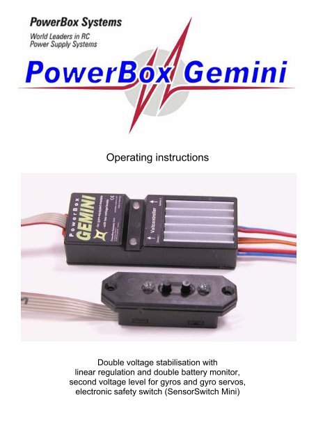
<strong>Operating</strong> <strong>instructions</strong><br />
Double voltage stabilisation with<br />
linear regulation and double battery monitor,<br />
second voltage level for gyros and gyro servos,<br />
electronic safety switch (SensorSwitch Mini)
POWER BOX Gemini<br />
Dear customer,<br />
We are delighted that you have decided to purchase the <strong>PowerBox</strong> Gemini from<br />
our range.<br />
Your valuable model aircraft can now be fitted with one of the most capable battery<br />
backers available, enabling you to couple two batteries battery backer) and also<br />
constantly monitor the voltage of the two batteries of your choice (NC, NiMH or<br />
LiPo).<br />
The minimum value of the battery voltage curves is stored, and can be called up<br />
again after each flight.<br />
The battery backer also provides a stabilised power supply (linear stabilisation)<br />
of 5.90 Volts for the receiver and servos.<br />
The special feature of the <strong>PowerBox</strong> Gemini is the second stabilised voltage level<br />
of 5.3 Volts, which can be used to power a gyro and the associated gyro servo.<br />
Although the unit is simple to operate, you do need to understand certain points if<br />
you are to exploit its advantages to the full. These <strong>instructions</strong> are designed to help<br />
you feel “at home” with your new equipment as quickly as possible. To ensure that<br />
this is the case, please read through these <strong>instructions</strong> attentively before using the<br />
power supply system for the first time.<br />
We hope you have many years of pleasure and success with your <strong>PowerBox</strong><br />
Gemini!<br />
Contents<br />
1. History of <strong>PowerBox</strong> <strong>Systems</strong> voltage-stabilised battery backers ....... - 4 -<br />
2. Product description.................................................................................... - 5 -<br />
3. Connections, controls................................................................................ - 8 -<br />
4. The Sensor-Switch ..................................................................................... - 9 -<br />
5. Setting the battery type............................................................................ - 11 -<br />
6. <strong>PowerBox</strong> Gemini block circuit diagram................................................ - 12 -<br />
7. Specification ............................................................................................. - 12 -<br />
8. <strong>Operating</strong> the unit, safety notes.............................................................. - 13 -<br />
9. Guarantee conditions............................................................................... - 15 -<br />
- 3 -
POWER BOX Gemini<br />
1. History of <strong>PowerBox</strong> <strong>Systems</strong> voltage-stabilised battery backers<br />
TOC 2002, Las Vegas: this is where the development of the first voltage-stabilised<br />
power supply systems for model aircraft began. In October 2002 Sebastiano<br />
Silvestri took part in the Tournament of Champions at Las Vegas; he was the first<br />
TOC participant to have a type of receiving system power supply installed in his<br />
Katana which had never been seen before. This was the <strong>PowerBox</strong> 40/24<br />
Professional, developed by us and an extremely successful unit, with “remotely<br />
accessed” channels (i.e. remote >from the receiver), signal amplification, voltage<br />
monitoring and much more besides - it could be summed up as a complete servo /<br />
receiver management system.<br />
At that time all the top European pilots were still flying their models with four-cell or<br />
five-cell NC batteries, or the then new NiMH packs, but in the USA many leading<br />
flyers were already using Li-Ion batteries made by the renowned battery<br />
manufacturer DuraLite. It was inevitable that Emory Donaldson, Manager of<br />
Duralite, would be present at the TOC, and he showed great interest in the type of<br />
power supply represented by the <strong>PowerBox</strong> Professional. There and then - in Las<br />
Vegas - he granted us a contract to develop a power supply system for DuraLite Li-<br />
Ion batteries, which have a voltage curve similar to the LiPo types now in common<br />
use (max. 8.4 Volts).<br />
In April 2003, at the “Joe Nall” event in Greenville, USA - only six months later - we<br />
were able to present him with a power supply system which contained linear<br />
voltage regulators - a completely new in-house development - electronic switches,<br />
voltage monitor etc.<br />
(Registered design DE 203 13 420.6)<br />
This ultra high-performance linear voltage stabilisation circuit has been employed<br />
unchanged in all our “regulated” battery backer systems and switches since 2003.<br />
All the companies which produce competing products have copied this idea, and<br />
fitted their battery backers not only with a regulated voltage circuit, but also the<br />
original <strong>PowerBox</strong> stabilisation circuit.<br />
For us and for our customers this is reassuring, and ample evidence of the<br />
rightness of our concept, since good ideas and innovative electronics always find<br />
their way to the front!<br />
- 4 -
POWER BOX Gemini<br />
2. Product description<br />
The <strong>PowerBox</strong> Gemini is a new kind of power supply system which contains all<br />
the latest electronic components which are necessary to provide power to highperformance<br />
servos and receivers. Basically, all the essential components, ICs,<br />
electronic circuits and programs required for a reliable power supply system are<br />
duplicated!<br />
This is in direct contrast with other manufacturers’ products which are powered by<br />
two batteries, and therefore give the impression of a dual power supply, but which<br />
contain no duplicated components - as required for a truly secure system. You have<br />
selected a product which offers genuine duplication of systems (system<br />
redundancy) in the interests of your safety. We believe it is important to emphasise<br />
this particular point, as we and most serious modellers accept it as a fundamental<br />
necessity that any device which is responsible for safety in an aircraft should<br />
always be present in a duplicated, or redundant form. This is precisely the approach<br />
taken by the <strong>PowerBox</strong> Gemini.<br />
The backer (battery change-over switch) function is based on an extremely highperformance<br />
12 Amp Dual Schottky diode; both diodes are housed in a single<br />
case. This diode arrangement ensures that voltage losses in operation are<br />
extremely low (0.25 Volt).<br />
If both batteries are in good condition, both contribute to the receiving system’s<br />
power supply. This means that each battery only bears half the total load, and both<br />
are recharged to the same level during the charge process. This arrangement<br />
avoids premature damage to your battery cells, and extends the useful life of your<br />
receiver packs significantly.<br />
During the charge process you will find that slightly more capacity can be charged<br />
into one battery, and slightly less into the other. This is normal, provided that the<br />
difference stays within the tolerance range of the components: after several flights<br />
this may be up to 100 - 150 mAh.<br />
This is the reason for the possible discrepancy:<br />
The <strong>PowerBox</strong> Gemini is fitted with two independent IC-controlled voltage<br />
regulators, i.e. one regulator for each battery. This duplication is known as<br />
redundancy. However, electronic components - like any other technical parts - are<br />
never 100% identical, i.e. all components are manufactured to a certain tolerance.<br />
We do take the greatest trouble to select components for our products which exhibit<br />
the tightest tolerances according to the manufacturer’s data sheets, but we cannot<br />
completely avoid minor deviations. Neither are all batteries 100% identical, so it is<br />
not possible to eliminate the problem just by the selection process.<br />
- 5 -
POWER BOX Gemini<br />
This means that a slight difference in the capacity of your batteries after several<br />
flights actually constitutes proof that your <strong>PowerBox</strong> Gemini contains two<br />
independent systems. We are aware that other systems always feed absolutely<br />
identical capacities into the batteries. We therefore ask you to consider for a<br />
moment whether this could really occur if - as claimed - the system contained two<br />
completely independent systems. Our experience obliges us to conclude that these<br />
alternative systems actually contain no duplicated circuitry - apart from the two<br />
batteries. Both batteries are simply discharged via one regulator, which provides<br />
power to the servos and the receiver.<br />
In our opinion a process of this type does not represent a system with redundancy,<br />
as required for valuable model aircraft and for safe modelling in general.<br />
Naturally all our <strong>PowerBox</strong>es are protected against reverse voltage which can be<br />
generated by servo motors.<br />
This measure is necessary because there are servos available on the market fitted<br />
with electronic circuitry which does not prevent reverse voltage.<br />
The situation is exacerbated by the existence of receivers which are not adequately<br />
protected against reverse servo voltage.<br />
If you use our <strong>PowerBox</strong>es you can be certain that it is safe to use all servos and<br />
receiver systems currently available.<br />
The <strong>PowerBox</strong> Gemini is equipped with two independent IC-controlled voltage<br />
monitors whose task is to check the performance of the two power sources. The<br />
two multi-colour LEDs in the housing of the <strong>PowerBox</strong> Gemini and the two ultrabright<br />
red LEDs in the SensorSwitch indicate the voltage of each battery separately.<br />
The multi-colour LEDs indicate the voltage level in four stages: green, orange,<br />
red, and flashing red. Under normal circumstances the ultra-bright red LEDs in the<br />
SensorSwitch flash briefly every two seconds. If their flashing frequency rises to a<br />
high level, this indicates that the corresponding battery is flat or almost flat. For this<br />
reason we recommend that you install the SensorSwitch and the <strong>PowerBox</strong><br />
Gemini in your model in such a position that you can clearly see these voltage<br />
monitor LEDs.<br />
- 6 -
POWER BOX Gemini<br />
Please believe what the voltage display tells you!<br />
You should check before every flight - by “stirring the sticks” - that the voltage of<br />
both batteries remains stable. If the batteries in your model are too “weedy” for the<br />
application, i.e. of inadequate capacity, this check will immediately show up the<br />
shortcoming. In general terms, small batteries of high capacity are not suitable for<br />
use as receiver power supplies because they have very high internal resistance;<br />
this means that their current delivery capacity is often inadequate for powerful, highspeed<br />
digital servos.<br />
For even better monitoring of the power sources, the battery backer also features a<br />
minimum value memory (low voltage memory) for both packs. This memory<br />
records all voltage collapses during the flight.<br />
This is a very important feature, as it provides you with important information<br />
regarding battery performance. You can now check the state and capability of your<br />
batteries in a long-term test (over the full duration of the flight) as well as in a brief<br />
pre-flight test.<br />
After each flight you can call up the minimum voltage memory by simultaneously<br />
“pressing” both sensor buttons before switching the system off.<br />
The memory is reset when you switch off the power supply system; the recording<br />
process begins anew when you next switch the system on.<br />
The voltage display is not linear, but matched to the discharge curve of today’s<br />
Nickel-Cadmium (NC), Nickel-Metal-Hydride (NiMH) and Lithium-Polymer (LiPo)<br />
cells. It is not possible to make general predictions regarding useful battery<br />
operating times, because this varies according to the battery capacity, the number<br />
of servos, the type of servos, and the frequency of control commands.<br />
- 7 -
POWER BOX Gemini<br />
3. Connections, controls<br />
The two receiver batteries are connected via the pair of integral Uni / JR sockets.<br />
In theory the <strong>PowerBox</strong> Gemini will also work with a single battery, but if you do<br />
this you forfeit the extra security of a dual-battery power supply. In principle you<br />
could connect one battery to both battery inputs using a Y-lead, in which case both<br />
switches and both regulators would be active. This arrangement would also allow<br />
the full regulator power of the <strong>PowerBox</strong> Gemini to be exploited.<br />
If you have to make up your own battery connecting leads, please take great care<br />
to avoid reversed polarity, as this would immediately destroy the battery backer’s<br />
linear regulators.<br />
Power is fed to the receiver and all the servos via the two servo leads (0.34 mm²,<br />
blue / red), which should be connected to the socket on your receiver marked “B”<br />
(battery) and any other vacant channel output socket.<br />
Connect the third servo lead (orange / red / brown) to the receiver output which<br />
controls the gyro and the associated gyro servo. The <strong>PowerBox</strong> Gemini only picks<br />
up and passes on the signal from this channel; at the other end of the unit you will<br />
find the socket for the gyro immediately adjacent to the red connector for the<br />
SensorSwitch. The signal picked up from the receiver is present at this socket, as is<br />
the second voltage level, which is set to 5.3 Volts.<br />
- 8 -
POWER BOX Gemini<br />
Of course, it is possible to connect two separate receivers to this battery backer. If<br />
you wish to do this be sure to observe the information supplied by your RC<br />
manufacturer concerning the use of two receivers in a model, otherwise there may<br />
be problems with interaction between the two units (minimum physical separation<br />
20 cm).<br />
Power is supplied to each receiver by one of the two integral servo leads.<br />
4. The Sensor-Switch<br />
The purpose of the SensorSwitch is to provide external control of the integral<br />
electronic switches in our <strong>PowerBox</strong> Gemini. The SensorSwitch does not switch<br />
the current for the servos and receiver. The actual switching process is carried out<br />
by the two completely independent electronic switches inside the battery backer.<br />
The switch plate houses two push-buttons and two ultra-bright red LEDs. The<br />
switch features two countersunk holes through which the retaining screws are fitted.<br />
The mounting bezel supplied provides a means of mounting the switch in the model<br />
securely without having to add an additional glued-in plate.<br />
Retaining screw<br />
Ribbon cable for connection<br />
to the <strong>PowerBox</strong> Gemini<br />
Switch button, Battery 1<br />
Two red<br />
ultra-bright LEDs<br />
Retaining screw<br />
Pressing both switch<br />
buttons simultaneously<br />
activates a read-out of the<br />
minimum value memory<br />
Switch button, Battery 2<br />
The pair of push-buttons is used to switch both power circuits on. This method of<br />
operation enables you to check individually each power circuit or battery.<br />
The method of using the buttons to switch on or off is always the same: hold the<br />
button pressed, and wait until the LED on the SensorSwitch lights up red, then<br />
release the button and press it briefly a second time.<br />
- 9 -
POWER BOX Gemini<br />
The LED flashes red every two seconds if this was the power-on procedure, or<br />
goes out if it was the power-off procedure.<br />
To check the two power circuits, switch on only one battery and watch the<br />
corresponding LED on the <strong>PowerBox</strong> Gemini to see whether and to what extent<br />
the battery voltage collapses when you “stir the sticks”. If everything is in order,<br />
switch this first battery off (LED goes out) and switch on the second battery. If<br />
everything is again in order, switch the first battery on again (both LEDs light up<br />
green). You have now checked both power systems.<br />
This new switch system provides you with an ultra-high level of security!<br />
The two ultra-bright red LEDs in the SensorSwitch provide the opportunity to<br />
monitor the batteries in flight: they flash at a very fast rate when the batteries are<br />
flat. If everything is working properly, these LEDs flash briefly every two or three<br />
seconds. If one battery is flat, the corresponding LED flashes very brightly and at a<br />
very rapid rate.<br />
When the unit is switched off, the “Standby” circuit of the electronic switches<br />
draws an idle current of around 5µA. This equates to a fraction of the self-discharge<br />
rate of normal batteries.<br />
The red plug on the ribbon cable attached to the SensorSwitch should be plugged<br />
into the red multi-pin socket on the right-hand side of the backer. Note that the<br />
switched state of the backer is not affected if the SensorSwitch is accidentally<br />
disconnected or comes adrift for any reason!<br />
Please take the trouble to deploy the ribbon cable in such a way that it is not<br />
subject to vibration!<br />
Don’t just let it dangle in the fuselage, and avoid placing it under strain. A small<br />
piece of double-sided foam tape between cable and fuselage is often all that is<br />
required.<br />
- 10 -
POWER BOX Gemini<br />
5. Setting the battery type<br />
The <strong>PowerBox</strong> Gemini is switchable to suit different battery types, i.e. you can<br />
switch the unit from five-cell NC to two-cell LiPo batteries yourself.<br />
The default setting is for LiPo batteries. If you wish to switch the unit for use with<br />
NC batteries, please use this procedure:<br />
Connect the two five-cell NC batteries to the unit; both LEDs now flash red, as the<br />
voltage monitor is set to LiPo by default.<br />
If you wish to reset the voltage monitor, please note that both monitor circuits have<br />
to be switched over separately using the two sensor buttons of the SensorSwitch.<br />
Simply hold the sensor button pressed in until the correct setting appears on the<br />
LED in set-up mode. This is the key:<br />
- LED flashes green once: two-cell LiPo battery<br />
- LED flashes green twice: five-cell NC battery<br />
Now we come to the method of setting the voltage monitor:<br />
- Hold one of the sensor buttons pressed in.<br />
- After about one second the colour of the LED changes to orange.<br />
- After a further three seconds the colour of the LED changes to red.<br />
- After a further five seconds the LED goes out briefly; now take care:<br />
- The LED flashes green once; if you release the button now, the voltage<br />
monitor is set to two-cell LiPo.<br />
- If you continue holding the button, the LED flashes green twice; release the<br />
button now, and the voltage monitor is set to five-cell NC or NiMH.<br />
- Repeat the procedure with the second button; both LEDs will now glow green -<br />
assuming that both NC batteries are fully charged.<br />
- 11 -
POWER BOX Gemini<br />
6. <strong>PowerBox</strong> Gemini block circuit diagram<br />
The block circuit diagram printed below is intended to clarify the function of the<br />
<strong>PowerBox</strong> Gemini. It represents the functional sequence of the individual<br />
components in graphic form:<br />
Battery 1<br />
Power supply<br />
CPU 1<br />
Linear regulator /<br />
electronic switch 1<br />
De-coupling diode1<br />
Receiver socket 1<br />
5,9 V +/-0,1V<br />
Switching<br />
voltage<br />
Sensor-<br />
Switch 1<br />
Micro-processor 1<br />
Indicator LED<br />
Battery 1<br />
Gyro socket<br />
Sensor –<br />
Switch 2<br />
Micro-processor 2<br />
Indicator LED<br />
Battery 2<br />
5,3 V +/-0,1V<br />
Switching<br />
voltage<br />
Battery 2<br />
Power supply<br />
CPU 2<br />
Linear regulator /<br />
electronic switch 2<br />
De-coupling diode 2<br />
Receiver socket 2<br />
5,9 V +/-0,1V<br />
7. Specification<br />
<strong>Operating</strong> voltage:<br />
4.0 to 9.0 Volts<br />
Power supply:<br />
Two 5-cell NiCd or NiMH batteries<br />
Two 2-cell LiPo batteries, 7.4 Volt<br />
Current drain:<br />
approx. 30 mA<br />
Voltage drop:<br />
approx. 0.30 V<br />
Max. receiver current:<br />
2 x 4 A (stabilised)<br />
Servo supply voltage:<br />
5.9 Volt<br />
Gyro supply voltage:<br />
5.3 Volt<br />
Max. continuous current: 10 A<br />
Temperature range:<br />
-10°C to +75°C<br />
Dimensions: 72 x 28 x 14 mm (L x W x H)<br />
Weight:<br />
32 g including all leads<br />
SensorSwitch:<br />
12 g<br />
- 12 -
POWER BOX Gemini<br />
8. <strong>Operating</strong> the unit, safety notes<br />
It is essential to use low-resistance batteries of the best possible quality to supply<br />
your receiving system. Don’t be tempted to use receiver packs of inadequate<br />
capacity, as just one of them will have to power the whole system on its own if one<br />
battery should fail in flight. We recommend that you use NC packs of at least 1700<br />
mAh capacity, and for large-scale models batteries of 3000 mAh or more are<br />
appropriate. You can use either Nickel-Cadmium (NC) batteries or Nickel-Metal-<br />
Hydride (NiMH) packs.<br />
If you decide to use modern, lightweight LiPo batteries, we recommend the<br />
<strong>PowerBox</strong> Battery 1500 and <strong>PowerBox</strong> Battery 2800 from our own range.<br />
These LiPo batteries currently represent the safest, most reliable battery packs<br />
available, as they contain a balancer and a low-voltage monitor as well as complete<br />
charge and security electronics.<br />
Charging these batteries is as simple as charging a mobile phone!<br />
Naturally, each battery set includes a practical mount and accessories.<br />
- 13 -
POWER BOX Gemini<br />
Install the battery backer in the model aircraft with adequate vibration protection, as<br />
used for the other components of the receiving system.<br />
Take care not to cover the heat-sink area.<br />
Please don’t just throw away the inner packaging, as it includes a template for<br />
marking the aperture for the SensorSwitch. Cut or saw clear of the marked line,<br />
as shown in the photo.<br />
Even though our products are very well protected from the effects of vibration, the<br />
switch should always be mounted in a part of the model relatively low in vibration.<br />
Please note that the GRP fuselage sides of a large power model are not suitable,<br />
as they are always subject to considerable vibration. You can remedy the situation<br />
by cutting a ply plate (2 - 3 mm thick) about 3 cm larger than the switch aperture,<br />
and gluing it in the appropriate place, as shown in the photo. The plate absorbs<br />
much of the vibration.<br />
- 14 -
POWER BOX Gemini<br />
The battery backer fulfils the EMV protection requirements, entitling it to bear<br />
the CE symbol. However, please note that the unit is designed and approved<br />
solely for use in modelling applications, and may only be used in radio-controlled<br />
models.<br />
It must never be connected to a mains PSU!<br />
9. Guarantee conditions<br />
During the production process each battery backer undergoes a series of tests. We<br />
take the maintenance of the highest quality standards very seriously, and that is<br />
why we are able to grant a 24 month guarantee on all our battery backer systems,<br />
valid from the initial date of purchase. The guarantee covers proven material faults,<br />
which will be corrected by us at no charge to you. We wish to emphasise expressly<br />
that we reserve the right to replace the unit if a repair is impossible for economic<br />
reasons.<br />
Proof of the commencement and progress of this guarantee period is the purchase<br />
receipt. Repairs which our Service Department carries out for you do not extend the<br />
guarantee period. Misuse and maltreatment, such as reversed polarity, excessive<br />
voltage and the effects of damp, invalidate the guarantee. The same applies to<br />
faults due to severe wear or excessive vibration. The guarantee does not cover any<br />
additional claims, such as consequent damage.<br />
We expressly deny liability for damages which are caused by the device, or<br />
arise through the use of the device.<br />
Liability exclusion:<br />
We are unable to ensure that you install and operate the battery backer correctly,<br />
nor that the entire radio control system has been maintained properly.<br />
For this reason we are unable to accept liability for loss, damages or costs<br />
which result from the use of the backer, or are connected with its use in any<br />
way.<br />
Unless otherwise prescribed by binding law, our obligation to pay compensation,<br />
regardless of the legal argument employed, is limited to the invoice value of that<br />
quantity of our products which was immediately and directly involved in the event<br />
which caused the damage.<br />
- 15 -
POWER BOX Gemini<br />
We wish you every success using your new battery backer, and hope you have<br />
loads of fun with it.<br />
Donauwörth, March 2007<br />
- 16 -
- 17 -<br />
POWER BOX Gemini
<strong>PowerBox</strong>-<strong>Systems</strong> GmbH<br />
Ludwig-Auer-Strasse 5<br />
D-86609 Donauwörth<br />
Germany<br />
Tel: +49-906-22 55 9<br />
Fax: +49-906-22 45 9<br />
info@<strong>PowerBox</strong>-<strong>Systems</strong>.com<br />
www.<strong>PowerBox</strong>-<strong>Systems</strong>.com