Pilatus PC-21 Depron-Version - HT-Modellbau
Pilatus PC-21 Depron-Version - HT-Modellbau
Pilatus PC-21 Depron-Version - HT-Modellbau

Create successful ePaper yourself
Turn your PDF publications into a flip-book with our unique Google optimized e-Paper software.
Recommended general procedures warranting best results of kit assembly:<br />
Polystyrene parts should be handled with care, do not put down heavy objects on them, do not put them on sharp edges, so that<br />
you would not damage their surface (by impact, too high finger pressure, etc.). These damages could be repaired by hair dryer or<br />
steam (it should be tested on a material sample!).<br />
Fit up parts for one operation on the desk without gluing. If necessary modify them and when they fit perfectly glue them<br />
in correct position.<br />
The parts are painted with alcohol-based paints, which are not resistant to paint thinners. In such areas where glue has to be<br />
applied, use the glue sparingly so that it would not flow out and with extreme care as not to damage the paint.<br />
Cut all PSH parts out with small overlap (cca 1 mm), modify them by grinding before gluing. Repair edges by a paint.<br />
Make the openings in PP parts with a safety razor, sharp knife or a scalpel. Blunt knife tears edges, the cut is not smooth!<br />
Glue the PP parts together with the UHU-por glue (or LA glue if necessary). Apply thin layer, spread well, let dry for a while and<br />
press parts together. Excessive UHU-por glue can be washed by gasoline (does not damage alcohol based paint). Glue strength<br />
joints with EPOXY. Tack the PSH parts (not PP parts!) with instant glue (CyA glue in the guide). Recommended type of glue is<br />
mentioned in the assembly illustrations.<br />
Clean milled edges of wooden parts by grinding with sandpaper before assembly.<br />
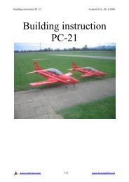
Assembly of Scale Model of<br />
"<strong>Pilatus</strong> <strong>PC</strong>-<strong>21</strong>"<br />
1) Before assembly application of decals on fuselage, wings and tail is recommended.<br />
The set of landing gear parts is not part of the kit, it is supplied separately.<br />
Connection of electric accessories "on the desk" is necessary!<br />
Optional parts:<br />
2x microservo 8g<br />
2x microservo 12g<br />
1x motor + regulator, Mega<br />
1x receiver, 5 channels<br />
2x extension cables of servos, 30 cm<br />
2x extension cables of servos for tail, 15cm<br />
1x battery 3 cell Li-Pol 1500 mAh<br />
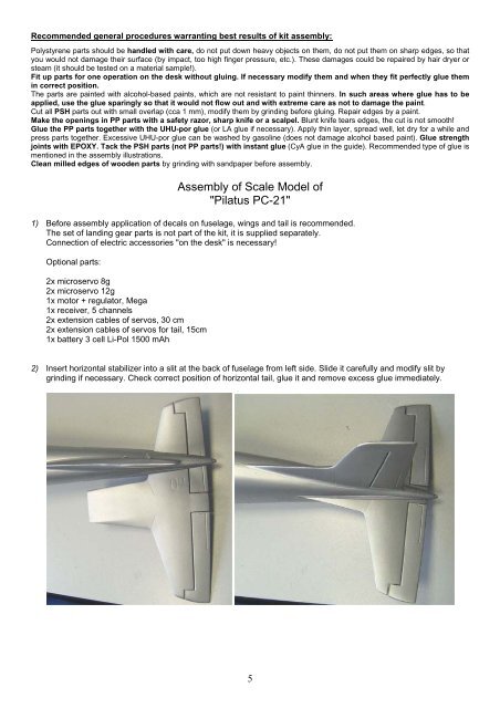
2) Insert horizontal stabilizer into a slit at the back of fuselage from left side. Slide it carefully and modify slit by<br />
grinding if necessary. Check correct position of horizontal tail, glue it and remove excess glue immediately.<br />
5
3) Install rod pins on levers of servos. Pass rods through bowdens in fuselage. Install servos into plywood plate in<br />
fuselage from below. Connect rods with servos and levers of rudder and elevator.<br />
4) Screw the motor with connected regulator to the bulkhead, pass it through the opening in bulkhead into fuselage.<br />
Put plastic motor hood on and check if shaft of the carrier passes through bonnet center and modify position of<br />
motor if necessary. Stick motor cover either to fuselage or fix it to inside spruce braces of fuselage using two<br />
screws.<br />
6
5) Cut a pad from balsa sheet according to battery size and cut out part of cockpit floor of the same size. You may<br />
make the pad longer so that you can move battery and modify the center of gravity. Glue balsa pad to fuselage.<br />
At the same time glue velcro to the pad and to the battery. Cut another pad from balsa for the receiver, fix it in<br />
front of batteries using velcro. Pass the antenna through fuselage and take it out through a small opening made at<br />
the back of fuselage.<br />
6) Remove carefully servo covers from wings and make slits for servo levers in them. Cut out opening for servos.<br />
Connect extension cables 30 cm to servos and pass them through the wing. Insert servos to prepared openings<br />
and stick bases of servos with a drop of glue. Glue servo covers in. Make links of aileron and servo levers from<br />
steel wire 0.8 mm and secure them with a drop of glue or with a piece of spaghetti.<br />
7) Cut and glue flap mechanism covers. Prepare openings in wings for their installation.<br />
WARNING! If you install landing gear, glue the covers into openings after installation of gear locks.<br />
If you are going to fly without landing gear, glue covers into slits and represent wheel tires using black paint.<br />
7
8) Make two parts from polypropylene strip 820 mm long and two 760 mm long. Glue the shorter parts to sides of<br />
front cockpit and longer parts to rear cockpit. Cut instrument panels out, paint them a glue them in. Assemble pilot<br />
seats, blind rear parts with parts cut from PP. Cut out parts of pilots, glue them together and caulk the seams.<br />
Paint pilots with light green-ochre paint, helmets with white paint. You can prepare oxygen mask tubes from<br />
pieces of spaghetti. Stick pilots to seats, you can prepare seat belts for better look. Install seats into fuselage.<br />
Assemble dial sight and glue it. Glue the cockpit.<br />
8
9) Assemble the spinner, propeller and install it. You can glue front part of the spinner or fix it with two screws.<br />
10) Deflections setting - ailerons can have slightly negative angle in basic position, max. 1 mm. Elevator slightly up at<br />
basic position, cca 1 mm.<br />
11) Insert batteries, install wing and verify correct position of the center of gravity. Modify it using batteries movement.<br />
67 - 72 mm from center leading edge at fuselage. Fix the wing with a plastic screw when connectors from<br />
receiver to aileron servos are connected. Be aware of a reaction moment of propeller when you launch model<br />
from the hand. It causes model tilting to left. Do not decrease throttle rapidly, make landing maneuver with<br />
running motor.<br />
12) Landing gear assembly<br />
Assemble the lock of nose gear from supplied parts and spruce lath so that steel wire would be inserted tightly to<br />
prepared opening. Prepare locks of main landing gear in the same way. Cut covers of landing gear wells and glue<br />
the lock of nose gear in. Locks of main landing gear will be glued to the lower wing covering. Assemble landing<br />
gear legs from supplied parts, glue shock absorbers from supplied parts to main legs, glue door rods and struts.<br />
Bend carefully nose gear cover and insert it into well. Modify main gear covers by bending ends to angle 90 o and<br />
by gluing bends, slide landing gear legs into locks, insert covers into locks and press legs to locks. Landing gear<br />
and wells are white.<br />
9
<strong>Pilatus</strong> <strong>PC</strong>-<strong>21</strong> Produce:<br />
<strong>HT</strong> <strong>Modellbau</strong><br />
Rebensweg 35<br />
CH-3293 Dotzingen<br />
Switzerland<br />
www.ht-modellbau.ch<br />
and<br />
FLYING STYRO KIT, spol. s r.o.<br />
J. Faimonové 11a, 628 00 BRNO, Czech Republic<br />
Tel.: 544<strong>21</strong>5000<br />
Fax: 544<strong>21</strong>0176<br />
e-mail: info@flyingstyrokit.cz<br />
www.flyingstyrokit.cz<br />
11