Maule Student Handbook - Henderson State University
Maule Student Handbook - Henderson State University
Maule Student Handbook - Henderson State University

Create successful ePaper yourself
Turn your PDF publications into a flip-book with our unique Google optimized e-Paper software.
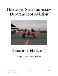
<strong>Henderson</strong> <strong>State</strong> <strong>University</strong><br />
Department of Aviation<br />
Record of Revisions<br />
<strong>Maule</strong> <strong>Student</strong> <strong>Handbook</strong><br />
Revision No. Page Action Remarks Initials<br />
1 All N/A 1. Original Issuance N/A<br />
2 All R 1. Page numbering system modified & Table of Contents added<br />
“ “ “ 2. SOPA changed to make flows more manageable and easier to<br />
understand<br />
“ “ “ 3. QRH changed to correspond with changes made to SOPA<br />
“ “ “ 4. Abbreviated checklist changed to correspond with changes<br />
made to SOPA<br />
“ “ “ 5. Expanded checklist changed to correspond with changes<br />
made to SOPA<br />
“ “ “ 6. Standardization Manual name changed to Standardized<br />
Maneuvers and Configurations (SMAC) to correspond with<br />
SOPA<br />
“ “ “ 7. SMAC (former Standardization Manual) changed to<br />
correspond with SOPA<br />
“ “ “ 8. (SMAC) Short Field Landing—Inputting 40 o Flaps is<br />
changed to the Final Leg instead of the Base Leg.<br />
“ “ “ 9. (SMAC) Soft Field Landing—Inputting 40 o Flaps is changed<br />
to the Final Leg instead of the Base Leg.<br />
10. Electrical system voltage added to Quick Reference<br />
Numbers<br />
“ A-1 A 11. Appendix 1 added (relocated MXT-7-160 AFM)<br />
“ A-2 A 12. Appendix 2 added (relocated MXT-7-180A AFM)<br />
“ A-3 A 13. Appendix 3 added – <strong>Maule</strong> Maintenance Guide (for<br />
reference only)<br />
A-4 A 14. Appendix 4 added – Depicts <strong>Maule</strong> cockpit flows<br />
A-5 A 15. Appendix 5 added – Briefing Guide<br />
Action Legend: R=Remove and Replace D=Delete and Destroy A=Add<br />
i
This Page Intentionally Left Blank.
<strong>Henderson</strong> <strong>State</strong> <strong>University</strong><br />
Department of Aviation<br />
List of Effective Pages<br />
<strong>Maule</strong> <strong>Student</strong> <strong>Handbook</strong><br />
Page(s) Date Page(s) Date Page(s) Date<br />
All 25-Aug-08<br />
All 24-Aug-09<br />
ii
This Page Intentionally Left Blank.
<strong>Henderson</strong> <strong>State</strong> <strong>University</strong><br />
Department of Aviation<br />
Table of Contents<br />
<strong>Maule</strong> <strong>Student</strong> <strong>Handbook</strong><br />
Section............................................................................................... Section-Page Number<br />
Record of Revisions ............................................................................................................ i<br />
List of Effective Pages ....................................................................................................... ii<br />
Table of Contents .............................................................................................................. iii<br />
Quick Reference Numbers .............................................................................................. 1-1<br />
Checklists ........................................................................................................................ 2-1<br />
Expanded Checklists ....................................................................................................... 3-1<br />
Standard Operating Procedures-Amplified (SOPA) ....................................................... 4-1<br />
Standardized Maneuvers and Configurations (SMAC) .................................................. 5-1<br />
<strong>Maule</strong> MXT-7-160 AFM .................................................................................. Appendix 1<br />
<strong>Maule</strong> MXT-7-180A AFM ............................................................................... Appendix 2<br />
<strong>Maule</strong> Maintenance Guide ................................................................................ Appendix 3<br />
Cockpit Flows ................................................................................................... Appendix 4<br />
Briefing Guide .................................................................................................. Appendix 5<br />
iii
This Page Intentionally Left Blank.
HENDERSON STATE UNIVERSITY<br />
DEPARTMENT OF AVIATION<br />
Quick Reference Numbers<br />
For the <strong>Maule</strong> MXT-7-160 & -180A
Quick Reference Numbers<br />
V SPD MXT-7-160 MXT-7-180A<br />
Do not exceed in any operation --------------- V NE ----------- 156 KIAS ------------ 161 KIAS<br />
Exceed only in smooth air --------------------- V NO ----------- 128 KIAS ------------ 129 KIAS<br />
No full/abrupt control inputs ------------------ V A ------------ 109 KIAS ------------ 109 KIAS<br />
Max flap extended speed ----------------------- V FE ------------- 82 KIAS ------------- 85 KIAS<br />
Stall speed landing configuration ------------- V S0 -------------- 38 KIAS ------------- 41 KIAS<br />
Stall speed clean configuration ---------------- V S1 -------------- 50 KIAS ------------- 53 KIAS<br />
Best angle of climb ----------------------------- V X -------------- 65 KIAS ------------- 65 KIAS<br />
Best rate of climb ------------------------------- V Y -------------- 78 KIAS ------------- 78 KIAS<br />
Max gliding distance speed -------------------- ------------------ 72 KIAS ------------- 72 KIAS<br />
Max crosswind component -------------------- ------------------ 13 KIAS ------------- 13 KIAS<br />
Max window open speed ----------------------- ---------------- 104 KIAS ------------ 104 KIAS<br />
Fuel grade ---------------------------------------- -------------------- 100LL ---------------- 100LL<br />
Fuel consumption (75% power) --------------- ---------------- 10.0 GPH ------------ 10.5 GPH<br />
Fuel consumption (65% power) --------------- ------------------ 8.8 GPH ------------- 9.5 GPH<br />
Oil grade ----------------------------------------- -------------- 15W50 X-C --------- 15W50 X-C<br />
Oil capacity -------------------------------------- ------------------- 8 quarts -------------- 8 quarts<br />
Max Weight -------------------------------------- ------------- 2200 Pounds -------- 2400 Pounds<br />
Electrical System Voltage --------------------- ---------------------------- -------------- 12 volts<br />
Fuel Capacity<br />
Aircraft Model Mains (Usable) Aux (Usable)<br />
N43HS --------- MXT-7-180A ---------- 21.5 gal/side --------------- N/A<br />
N54HS ---------- MXT-7-160 ----------- 21.5 gal/side --------------- N/A<br />
N57HS ---------- MXT-7-160 ----------- 21.5 gal/side --------------- N/A<br />
N79HS ---------- MXT-7-160 ----------- 21.5 gal/side --------------- N/A<br />
N103HS -------- MXT-7-160 ----------- 21.5 gal/side --------------- N/A<br />
N110HS -------- MXT-7-160 ----------- 21.5 gal/side --------------- N/A<br />
N114HS ------- MXT-7-180A ---------- 21.5 gal/side ---------- 15.0 gal/side<br />
N125HS ------- MXT-7-180A ---------- 21.5 gal/side ---------- 15.0 gal/side<br />
N136HS ------- MXT-7-180A ---------- 21.5 gal/side ---------- 15.0 gal/side<br />
N152HS ------- MXT-7-180A ---------- 21.5 gal/side ---------- 15.0 gal/side<br />
N171HS ------- MXT-7-180A ---------- 21.5 gal/side ---------- 15.0 gal/side<br />
1. This airplane must be operated as a normal category airplane in compliance with the<br />
operating limitations stated in the flight manual and in the form of placards and markings.<br />
2. No aerobatic maneuvers including spins, approved.<br />
3. Maneuvering speed: 109KIAS.<br />
4. This airplane approved for day or night IFR non-icing flight when equipped in accordance<br />
with FAR 91 or FAR 135.<br />
5. Do not turn off alternator in flight except in case of emergency.<br />
6. Fuel remaining in tank when indicator reads zero cannot be used safely in flight.<br />
7. See loading instruction sin weight and balance section of airplane flight manual.<br />
8. Demonstrated crosswind 13 knots.<br />
HSU-AVN <strong>Maule</strong> <strong>Student</strong> <strong>Handbook</strong> Page 1-1
This Page Intentionally Left Blank.<br />
HSU-AVN <strong>Maule</strong> <strong>Student</strong> <strong>Handbook</strong> Page 1-2
HENDERSON STATE UNIVERSITY<br />
DEPARTMENT OF AVIATION<br />
Aircraft Checklists<br />
For the <strong>Maule</strong> MXT-7-160 & -180A
Preflight Walk-around Inspection (Read & Do)<br />
1. Left Wing Fuel Drain ---------------------- DRAIN<br />
2. Fuselage Fuel Drain ------------------------ DRAIN<br />
3. Left Landing Gear ----------------------- INSPECT<br />
4. Left Flap ---------------------------------- INSPECT<br />
5. Left Aileron ------------------------------ INSPECT<br />
6. Left Wing Tip ---------------------------- INSPECT<br />
7. Left Landing Light ---------------------- INSPECT<br />
8. Left Tie Down --------------------------- REMOVE<br />
9. Pitot Tube --------------------------------- INSPECT<br />
10. Stall Warning Switch ------------------- INSPECT<br />
11. Left Fuel Vents -------------------------- INSPECT<br />
12. Left Wing Top --------------------------- INSPECT<br />
13. Left Wing Tank ---------------------------- CHECK<br />
14. Gascolator ----------------------------------- DRAIN<br />
15. Propeller ---------------------------------- INSPECT<br />
16. Air Intakes -------------------------------- INSPECT<br />
17. Tow Bar ----------------------------------- REMOVE<br />
18. Nose Gear -------------------------------- INSPECT<br />
19. Oil Quantity -------------------------------- CHECK<br />
20. Right Wing Top-------------------------- INSPECT<br />
21. Right Fuel Tank---------------------------- CHECK<br />
22. Right Fuel Vents ------------------------- INSPECT<br />
23. Right Tie Down -------------------------- REMOVE<br />
24. Right Landing Light --------------------- INSPECT<br />
25. Right Wing Tip -------------------------- INSPECT<br />
26. Right Aileron ----------------------------- INSPECT<br />
27. Right Flap -------------------------------- INSPECT<br />
28. Right Fuel Drain ---------------------------- DRAIN<br />
29. Right Landing Gear --------------------- INSPECT<br />
30. Right Fuselage --------------------------- INSPECT<br />
31. Cargo Door -------------------------------- SECURE<br />
32. Right Static Port --------------------------- CLEAR<br />
33. Right Stabilizer -------------------------- INSPECT<br />
34. Right Elevator ---------------------------- INSPECT<br />
35. Rudder ------------------------------------ INSPECT<br />
36. Tail Skid / Tie Down -------------------- REMOVE<br />
37. Left Elevator ----------------------------- INSPECT<br />
38. Left Stabilizer ---------------------------- INSPECT<br />
39. Left Fuselage ----------------------------- INSPECT<br />
40. Left Side Static Port ----------------------- CLEAR<br />
SAFETY CHECK (Read & Do)<br />
All Electrical Switches ----------------------------- OFF<br />
Magnetos ---------------------- OFF, KEY REMOVED<br />
BAT Switch ------------------------------------------- ON<br />
Fuel Qty ----------------------- CHECKED (REFUEL)<br />
Exterior Lights (Night) -------------------- CHECKED<br />
BAT Switch ------------------------------------------ OFF<br />
PREFLIGHT CHECK<br />
Squawk Book --------------- CHECKED, AC_____<br />
Weight & Balance ---------------------- COMPLETE<br />
Hobbs ----------------------------------- RECORDED<br />
Exterior Check -------------------------- COMPLETE<br />
Fuel ---------------- FLT PLAN FUEL ON BOARD<br />
Parking Brake ------------------------------------- SET<br />
Circuit Breakers -------------- (BOTH) CHECKED<br />
Fuel Selectors ------------------- BOTH SELECTED<br />
Flaps --------------------------------------------------- 0°<br />
Trim -------------------------------- SET, TAKE OFF<br />
Seatbelts ---------------------- (BOTH) FASTENED<br />
Crew/ Pax Briefing --------------------- COMPLETE<br />
BEFORE START CHECK<br />
BAT & ALTR Switches -------------------------- ON<br />
Anti-Collision Lights ----------------------------- ON<br />
Nav Lights ---------------------------------- OFF (ON)<br />
Ramp -------------------------------- (BOTH) CLEAR<br />
BEFORE TAXI CHECK<br />
Oil Pressure ------------------------------ CHECKED<br />
Alternator --------------------------------- CHECKED<br />
Altimeter ----------------- (BOTH) __.__IN, ____FT<br />
Heading --------- SET, ___ DEGREES, NORMAL<br />
Flight Plan ---------------------- SET, ACTIVATED<br />
TAXI CHECK<br />
Flight Instruments ------------ (BOTH) CHECKED<br />
Flight Controls --------------------------- CHECKED<br />
ENGINE CHECK (Read & Do)<br />
Parking Brake ------------------------------------- SET<br />
Power -------------------------------------- 2000 RPM<br />
Magnetos --------------------------------- CHECKED<br />
Carburetor Heat -------------------------- CHECKED<br />
Vacuum Pressure ------------------------ CHECKED<br />
Engine Instruments ----------------------- NORMAL<br />
Alternator -------------------------------- CHARGING<br />
Power --------------------------------------------- IDLE<br />
Heading -------------- (BOTH) SET, ___DEGREES<br />
Altimeter ----------------- (BOTH) __.__IN, ____FT<br />
Burn Out/Time on Grd -------------- __:__Z, __:__Z<br />
Doors ----------------------------------------- CLOSED<br />
Passengers ---------------------------------- BRIEFED<br />
HSU-AVN <strong>Maule</strong> <strong>Student</strong> <strong>Handbook</strong> Page 2-1<br />
(REV 1)
TAKE OFF PROCEDURES<br />
Normal/ X-W Short Field Soft Field<br />
Flaps 0° Flaps 24° Flaps 24°<br />
V R 52 KTS V R 48 KTS V R ≈48 KTS<br />
Target Pitch Attitude<br />
Pitch ≈8° Pitch ≈8° Pitch ≈8°<br />
V Y 78 KTS V X 65 KTS V X 65KTS<br />
BEFORE TAKEOFF CHECK<br />
Take Off Briefing ------------------------ COMPLETE<br />
Flaps ----------------- SET, __DEGREES, VERIFIED<br />
V SPDS --------------__, __, CHECKED & SET<br />
Transponder ------------------- SET____, ALTITUDE<br />
Landing Lights --------------------------------------- ON<br />
CLIMB CHECK<br />
Flaps ---------------------------------------------------- 0°<br />
Cruise Climb ------------------------------ _______KTS<br />
CRUISE CHECK<br />
Landing Lights -------------------------------------- OFF<br />
Flaps -------------------------------------- (X-C only) -7°<br />
Power ------------------------------------------------- SET<br />
Mixture ------------ (at/above 3000’ X-C only) LEAN<br />
Systems --------------------------- (BOTH) CHECKED<br />
DESCENT CHECK<br />
Landing Lights --------------------------------------- ON<br />
Altimeter ----------------- (BOTH) __.__IN, _____FT<br />
Mixture --------------------------------------------- RICH<br />
Fuel Selectors ------------------------------------- BOTH<br />
Aircraft Systems ---------------- (BOTH) CHECKED<br />
LANDING FLAPS AND V REF SPEEDS<br />
Normal Landing X-Wind Short/Soft Field<br />
Flaps 24° Flaps 0° Flaps 40°<br />
V REF 61 KTS V REF 65 KTS V REF 52 KTS<br />
GA Procedure<br />
TOGA Power, Target Pitch 8°<br />
Retract Flaps to 24°, V X 65 KTS,<br />
@ 500 ft AGL Flaps 0°, V Y 78 KTS<br />
APPROACH CHECK<br />
Passenger Briefing ----------------------- COMPLETE<br />
Landing/GA Procedure --------------------- BRIEFED<br />
Flaps __, V REF ------------------------------- __ KNOTS<br />
(IFR flight)<br />
Approach Briefing ------------------------ COMPLETE<br />
Minimums --------------------- (BOTH) SET, ____FT<br />
App Freq & Crs ------------- (BOTH) ___, ___INBD<br />
LANDING CHECK<br />
Mixtures ------------------------------------------- RICH<br />
Carburetor Heat -------------------------------------- ON<br />
Flaps -------------------------------- SET, __ DEGREES<br />
AFTER LANDING CHECK<br />
(Clear of runway)<br />
Transponder -------------------------------- STBY (ON)<br />
Landing Lights ----------------------- OFF (ON-Night)<br />
Carburetor Heat ------------------------------------- OFF<br />
Flaps ----------------------------------------------------- 0°<br />
Trim ----------------------------------- SET, TAKE OFF<br />
PARKING CHECK<br />
Avionics Switch ------------------------------------ OFF<br />
Mixture--------------------------------- IDLE CUT-OFF<br />
Electrical Switches --------------------------------- OFF<br />
Panel Lights ----------------------------------------- OFF<br />
BAT & ALTR Switches --------------------------- OFF<br />
Magnetos --------------------- OFF, KEY REMOVED<br />
Parking Brake --------------------------------------- OFF<br />
SECURING CHECK (Read and Do)<br />
Hobbs/ Tachometer ----------------------RECORDED<br />
Maintenance Write Ups ------------------RECORDED<br />
Controls -------------------------------------- SECURED<br />
Doors ------------------------------------------- CLOSED<br />
Baggage Door --------------------------------- CLOSED<br />
Tie Down ------------------------------------ SECURED<br />
HSU-AVN <strong>Maule</strong> <strong>Student</strong> <strong>Handbook</strong> Page 2-2<br />
(REV 1)
HENDERSON STATE UNIVERSITY<br />
DEPARTMENT OF AVIATION<br />
Expanded Checklists<br />
For the <strong>Maule</strong> MXT-7-160 & -180A
MAULE MXT-7 CHECKLIST<br />
(Expanded Checklist)<br />
The purpose of the expanded checklist is to assist a pilot new to the <strong>Maule</strong> MXT-7. The format<br />
for the following pages allows for expanded explanation of what the pilot will be looking for and<br />
how a system is tested. Often a single response implies that several items have been done and<br />
completed.<br />
The checklist with exception is designed to verify that something has been done or checked or a<br />
switch selected. Therefore, it is a Read and Verify list. Therefore, the pilot is expected to<br />
complete a flow of items when triggered by a phase of flight. Once the procedural flow is<br />
complete, call for the appropriate checklist and respond to each challenge with the correct<br />
response as verification.<br />
There are three (3) exceptions. The “SAFETY CHECK”, “ENGINE CHECK”, and<br />
“SECURING CHECK” are Read and Do checklists. The “SAFETY CHECK” is Read and Do<br />
for safety reasons. The “ENGINE CHECK” is Read and Do because of the depth of test and<br />
checks performed. Finally, the “SECURING CHECK” is Read and Do because of the<br />
randomness of the activities performed.<br />
SAFETY CHECK (Read & Do)<br />
The “SAFETY CHECK” is designed to protect crew, passengers, and persons on the ramp as<br />
well as the aircraft from harm and damage. Since the aircraft is un-powered applying power can<br />
cause systems to activate if not verified off.<br />
All Electrical Switches --------------------------------------------- OFF<br />
Scan the entire instrument panel and verify all switches are off.<br />
Verify that the Avionics master switch is off to protect the radio.<br />
Magnetos ------------------------------------------- Off, Key Removed<br />
Verify that the Switch is in the OFF position and the key is<br />
removed. Place the key on the glare shield as further confirmation<br />
that the magneto switch is OFF.<br />
BAT Switch ----------------------------------------------------------- ON<br />
The Master Switch is a split rocker. Select the left side BAT<br />
Switch only.<br />
Fuel Qty -------------------------------------- CHECKED (REFUEL)<br />
Check the fuel quantity indicators and determine if an adequate<br />
amount of fuel is on board for the intended flight. It is HSU policy<br />
that the aircraft always has a minimum of half tanks for local<br />
flights and maximum allowable for cross country. Make note of<br />
the exact position of the fuel indicator to check against the visual<br />
check of the fuel during the exterior preflight. The AUX tank, if<br />
HSU-AVN Expanded Checklist Page 3-1<br />
(REV 1)
installed as policy should remain empty unless authorized to use.<br />
If fuel in the AUX tank then the current W&B is void and a new<br />
W&B must be computed.<br />
Exterior Lights (Night) ----------------------------------- CHECKED<br />
Verify that all lights are in working condition for night flights.<br />
BAT Switch ---------------------------------------------------------- OFF<br />
PREFLIGHT CHECK<br />
Squawk Book ------------------------------------ CHECKED, AC___<br />
Verify that you have the correct AC squawk book. Check if there<br />
are any open write ups and determine if the flight is legal and safe.<br />
Weight & Balance --------------------------------------- COMPLETE<br />
Hobbs ------------------------------------------------------ RECORDED<br />
Exterior Check ------------------------------------------- COMPLETE<br />
The complete walk around checklist can be found in the QRH.<br />
Fuel ---------------------------- FLIGHT PLAN FUEL ON BOARD<br />
Verify that the fuel on board meets all the requirements for the<br />
flight. Further, verify that the aircraft has the minimum fuel on<br />
board per HSU FOM. (Minimum ½ tanks)<br />
Parking Brake ------------------------------------------------------- SET<br />
Be sure not to overly press down on the brake peddles; doing so<br />
might prevent or make it difficult to release the parking brake later.<br />
Circuit Breakers ------------------------------- (BOTH) CHECKED<br />
All circuit breakers must be set unless collared by maintenance. It<br />
remains the pilot’s responsibility to verity that all systems required<br />
for flight are available and working.<br />
Fuel Selector ------------------------------------------------------ BOTH<br />
The Fuel Selector should be in the (Both) position for Take Off<br />
and Landing.<br />
Flaps -------------------------------------------------------- 0 DEGREES<br />
Verify that the flaps have been returned to 0 degrees after the walk<br />
around is complete.<br />
Trim --------------------------------------------------- SET, TAKE OFF<br />
HSU-AVN Expanded Checklist Page 3-2<br />
(REV 1)
Seatbelts ----------------------------------------- (BOTH) FASTENED<br />
As part of the Passenger briefing verify that all seatbelts are<br />
fastened.<br />
Pax/ Crew Briefing -------------------------------------- COMPLETE<br />
Brief the Passengers on the requirement to wear the seatbelt for all<br />
takeoffs and landings. Assist in buckling as needed. Further, brief<br />
the Pax on the sterile flight deck rules. Brief on how to exit the<br />
aircraft in case of an emergency and where the fire extinguisher is<br />
and how to use it. Finally, share with the passengers the weather<br />
and expected comfort level of the flight.<br />
The purpose of the crew briefing is to establish and discuss the<br />
conduct of the flight. It is during this briefing that the PIC will be<br />
established and who will be the PF (pilot flying) and who the PM<br />
(pilot monitoring) will be. Discuss the effects of the weather on<br />
the flight and any and all modifications to the flight that are<br />
needed.<br />
BEFORE START CHECK<br />
BAT & ALTR Switches -------------------------------------------- ON<br />
Anti-Collision Lights ------------------------------------------------ ON<br />
Nav Lights ----------------------------------------------------- OFF (ON)<br />
Navigation Lights are required to be on between official sunset<br />
through official sunrise.<br />
Ramp -------------------------------------------------- (BOTH) CLEAR<br />
Visually check around the aircraft to confirm that the area is clear<br />
for an engine start.<br />
BEFORE TAXI CHECK<br />
Oil Pressure ------------------------------------------------- CHECKED<br />
Caution: If oil pressure doesn’t exceed 25 psi within 30 seconds<br />
shut down the engine<br />
Alternator --------------------------------------------------- CHECKED<br />
Verify that the alternator is charging the battery (a positive needle<br />
to the right on the ammeter). If the ammeter needle is deflected to<br />
the left the alternator isn’t working and the battery is discharging<br />
requiring that the flight be terminated.<br />
HSU-AVN Expanded Checklist Page 3-3<br />
(REV 1)
Altimeter ------------------------- (BOTH) __.__ INCHES, ____FT<br />
The PIC will set the altimeter and both pilots will verify that the<br />
altimeter is reading field elevation (+/- 75 feet maximum<br />
difference). By reading the altitude the pilot is verifying that the<br />
altimeter setting was set correctly and that the altimeter is reading<br />
correctly.<br />
Heading ----------------------------- Set, ___ DEGREES, NORMAL<br />
The purpose of setting the Heading Indicator at this time is to assist<br />
the pilot in situational awareness during taxing. It is quite<br />
possible that the gyro is not completely spun up therefore the<br />
Heading Indicator is prone to precession and will be reset during<br />
Engine run up. Stating “Normal” confirms the Compass indicates<br />
level and the fluid level should be full.<br />
Flight Plan----------------------------------------- SET, ACTIVATED<br />
Load the flight plan in the GPS. If the flight is local, load the<br />
departure airport in the GPS.<br />
TAXI CHECK<br />
Flight Instruments ----------------------------- (BOTH) CHECKED<br />
During turns (S turns if needed) verify that the Heading Indicator<br />
and the Compass are turning correctly and in the right direction<br />
and rate. The Turn Coordinator should show a turn in the correct<br />
direction and the ball should move in the opposite direction. The<br />
Attitude Indicator should maintain level flight.<br />
Flight Controls --------------------------------------------- CHECKED<br />
Check both for freedom of movement and correct deflection of<br />
control surfaces in response to control wheel movement. This<br />
should be done using the “box method”. (with controls pushed<br />
forward, deflect fully to the left…with controls fully to the left,<br />
pull full aft…with controls full aft, deflect fully to the right…with<br />
controls fully to the right, push full forward)<br />
ENGINE CHECK (Read & Do)<br />
Parking Brake ------------------------------------------------------- SET<br />
Power ---------------------------------------------------------- 2000 RPM<br />
Verify that the engine is operating in the normal range before<br />
doing the Engine Check.<br />
HSU-AVN Expanded Checklist Page 3-4<br />
(REV 1)
Magnetos ---------------------------------------------------- CHECKED<br />
Maximum drop of 175 RPM per magneto allowed and a maximum<br />
difference of 50 RPM.<br />
Carburetor Heat ------------------------------------------- CHECKED<br />
The use of carburetor heat should cause a drop in engine rpm.<br />
Normal drop 150 RPM +/- 50 RPM.<br />
Vacuum Pressure ----------------------------------------- CHECKED<br />
Verify Vacuum gauge reads in the green arc during engine run up.<br />
At idle the vacuum reads low.<br />
Engine Instruments ---------------------------------------- NORMAL<br />
The engine should be running smoothly and all engine indications<br />
should be normal.<br />
Alternator ------------------------------------------------- CHARGING<br />
The ammeter should read a positive charge and the Alternator<br />
INOP Light – Out<br />
Power ----------------------------------------------------------------- IDLE<br />
Heading ------------------------------- (BOTH) SET, ___ DEGREES<br />
The Heading Indicator should turn in the right direction during taxi<br />
verifying that it is operating normally. Reset the Heading Indicator<br />
to the current compass heading.<br />
Altimeter ------------------------- (BOTH) __.__ INCHES, ____ FT<br />
<strong>State</strong> the barometric pressure and read the altitude verifying that<br />
the altimeter is correct.<br />
Burn out/Time on Ground --------------------------- __:__Z, __:__Z<br />
Compute the time till fuel exhaustion and one (1) hour less for<br />
Time on Ground. The clock should be set to UTC (Zulu). <strong>State</strong><br />
times in Zulu.<br />
Doors ------------------------------------------------------------ CLOSED<br />
Passengers ----------------------------------------------------- BRIEFED<br />
Notify the passengers that the aircraft is about to takeoff and share<br />
with them any information that will help to alleviate any concerns<br />
they might have about the flight.<br />
HSU-AVN Expanded Checklist Page 3-5<br />
(REV 1)
Take Off Procedures<br />
Normal/ X-W Short Field Soft Field<br />
Flaps 0° Flaps 24° Flaps 24°<br />
V R 52 KTS V R 48 KTS V R ≈48 KTS<br />
Target Pitch Attitude<br />
Pitch ≈8° Pitch ≈8° Pitch ≈8°<br />
V Y 78 KTS V X 65 KTS V X 65KTS<br />
HSU-AVN Expanded Checklist Page 3-6<br />
(REV 1)
BEFORE TAKEOFF CHECK<br />
Take Off Briefing ---------------------------------------- COMPLETE<br />
Determine the type of Takeoff that will be used, and brief all data<br />
from the Takeoff Procedures Guide. Reference the “Before<br />
Takeoff Briefing” in the QRH if needed to brief the crew: i.e.:<br />
Initial heading & altitude, abort procedure, return to field, etc.<br />
Flaps -------------------------------- SET, __DEGREES, VERIFIED<br />
Visually verify that the correct flaps are set based on Takeoff<br />
briefing.<br />
V SPDS --------------------------------------- __, __, CHECKED & SET<br />
From the Takeoff Procedures Guide determine and set the V<br />
speeds.<br />
Transponder ------------------------- CODE SET____, ALTITUDE<br />
Verify code and altitude is selected<br />
Landing Lights ------------------------------------------------------ ON<br />
CLIMB CHECK<br />
Flaps ---------------------------------------------------------------------- 0°<br />
If other than normal takeoff procedures were used verify that the<br />
flaps have been retracted to 0°. Flaps should not be retracted<br />
beyond 24° until reaching 500 ft AGL.<br />
Cruise Climb--------------------------------------------------_____KTS<br />
In normal operations, the cruise climb airspeed will be at least 85<br />
knots. Conditions may cause the aircraft’s climb rate to be lower<br />
than 500 fpm at this speed. In this case, speed should be slowed to<br />
maintain at least a 500 fpm climb. Speed should not be slowed<br />
below V Y (78 knots).<br />
CRUISE CHECK<br />
Landing Lights ------------------------------------------------------ OFF<br />
Do not turn landing lights off until reaching cruise altitude and 10<br />
miles or greater from the airport. The FAA recommends that all<br />
pilots comply with “Operation Lights On” which calls for landing<br />
lights to be on when below 10,000 feet.<br />
HSU-AVN Expanded Checklist Page 3-7<br />
(REV 1)
Flaps ----------------------------------------------------- (-7) DEGREES<br />
If flight is to another airport retract flaps to the -7 degrees position<br />
for optimum fuel and TAS.<br />
Power ------------------------------------------------------------------ SET<br />
2500 rpm should be considered the maximum cruise power setting.<br />
Consider using 2200 to 2400 rpm for fuel conservation and engine<br />
wear and tear. This will also provide a more comfortable cabin<br />
noise level for the crew and passengers.<br />
Mixture ----------------------------- (at/above 3000’ X-C only) Lean<br />
HSU requires that the pilot use 75 degrees rich of peak for leaning<br />
for all X-C flights.<br />
Systems ------------------------------------------ (BOTH) CHECKED<br />
Cross check the electrical, vacuum, fuel, and engine systems for<br />
normal operations.<br />
DESCENT CHECK<br />
Landing Lights ------------------------------------------------------- ON<br />
Altimeters ---------------------------- (BOTH) __.__Inches, ____FT<br />
Obtain weather and airport information prior to descent point.<br />
Mixture ------------------------------------------------------------- RICH<br />
Increase mixture to full rich slowly as needed consistent with the<br />
amount of altitude to lose.<br />
Fuel Selector ------------------------------------------------------ BOTH<br />
Aircraft Systems ------------------------------- (BOTH) CHECKED<br />
Scan the engine instruments, ammeter, and the vacuum gage for<br />
system status.<br />
Landing Flaps and V REF Speeds<br />
Normal Landing X-Wind Short/Soft Field<br />
Flaps 24° Flaps 0° Flaps 40°<br />
V REF 61 KTS V REF 65 KTS V REF 52 KTS<br />
GA Procedure<br />
TOGA Power, Target Pitch 8°<br />
Retract Flaps to 24°, V X 65 KTS,<br />
@ 500 ft AGL Flaps 0°, V Y 78 KTS<br />
HSU-AVN Expanded Checklist Page 3-8<br />
(REV 1)
APPROACH CHECK<br />
Passenger Briefing --------------------------------------- COMPLETE<br />
Advise the passengers of the approximate arrival time. Verify that<br />
seatbelts are fastened and the passengers have been briefed on any<br />
specific flight conditions that they may need to know.<br />
Landing/ GA Procedure ------------------------------------ BRIEFED<br />
Brief the type of landing that will be performed along with the<br />
correct flaps and speeds to flown. Complete the briefing by<br />
reviewing the GA procedures listed above.<br />
Flaps __, V REF ----------------------------------------------- __ KNOTS<br />
Set speed to be used on landing based on the Landing Flaps and<br />
V REF Speeds table.<br />
(IFR flight)<br />
Approach Briefing --------------------------------------- COMPLETE<br />
Reference the “Approach Briefing” in the QRH if needed to brief<br />
the crew.<br />
Minimums --------------------------------------- (BOTH) Set, ____ FT<br />
Set Approach minimum altitude. If flying a visual approach set<br />
runway threshold elevation.<br />
App Freq & Course ------------------------- (BOTH) ___, ___INBD<br />
Verify and state the correct approach frequency and the final<br />
approach course inbound. If flying a GPS approach state “GPS”<br />
and the course inbound.<br />
LANDING CHECK<br />
Mixture ------------------------------------------------------------ RICH<br />
Carburetor Heat ----------------------------------------------------- ON<br />
Flaps ------------------------------------------------ SET, __ DEGREES<br />
Flaps are not to be extended unless at or below V FE (82 KIAS -160,<br />
85 KIAS -180A). Announce the current flap setting at the reading<br />
of the checklist. If this setting is different than the briefed flap<br />
setting for the landing, state the final flap setting and when it will<br />
be achieved, ex. “Flaps”-------“24 o , 40 o on Final”.<br />
HSU-AVN Expanded Checklist Page 3-9<br />
(REV 1)
AFTER LANDING CHECK<br />
(Clear of runway)<br />
Transponder ------------------------------------------------ STBY (ON)<br />
Note: The airport may require that the transponder remain on<br />
during taxi.<br />
Landing Lights ---------------------------------------- Off (ON-Night)<br />
Carburetor Heat ------------------------------------------------------ Off<br />
Flaps -------------------------------------------------------- 0 DEGREES<br />
Verify flaps are set to 0 degrees and not -7 degrees<br />
Trim --------------------------------------------------- SET, TAKE OFF<br />
PARKING CHECK<br />
Avionics Switch ----------------------------------------------------- OFF<br />
Electrical Switches -------------------------------------------------- OFF<br />
Mixture ------------------------------------------------ IDLE CUT-OFF<br />
Panel Lights ---------------------------------------------------------- OFF<br />
BAT & ALTR Switches ------------------------------------------- OFF<br />
Magnetos ------------------------------------- OFF, KEY REMOVED<br />
After removing the keys place them on the glare shield.<br />
Parking Brake ------------------------------------------------------- OFF<br />
Determine the status of the aircraft. If there is any chance that the<br />
aircraft could move do to weather keep the parking park set until<br />
the aircraft is secure. Furthermore, if required advice the lineman<br />
that the aircraft parking brake is set or insure that a tug is<br />
connected to the aircraft before releasing the parking brake.<br />
HSU-AVN Expanded Checklist Page 3-10<br />
(REV 1)
SECURING CHECK (Read & Do)<br />
Hobbs/ Tachometer ------------------------------------- RECORDED<br />
Maintenance Write Ups -------------------------------- RECORDED<br />
Controls ------------------------------------------------------- SECURED<br />
Doors ------------------------------------------------------------ CLOSED<br />
Lock the doors if on overnight or if it is the last flight of the day.<br />
If in doubt, lock the doors.<br />
Baggage Door -------------------------------------------------- CLOSED<br />
Tie Down ----------------------------------------------------- SECURED<br />
HSU-AVN Expanded Checklist Page 3-11<br />
(REV 1)
This Page Intentionally Left Blank.<br />
HSU-AVN Expanded Checklist Page 3-12<br />
(REV 1)
HENDERSON STATE UNIVERSITY<br />
DEPARTMENT OF AVIATION<br />
Standard Operating Procedures-Amplified<br />
(SOPA)<br />
For the <strong>Maule</strong> MXT-7-160 & -180A
STANDARD OPERATING PROCEDURES AMPLIFIED (SOPA)<br />
In developing standards for flying an aircraft the goal is to first and for most be safe and then efficient.<br />
The pilot in command is responsible for the airworthiness of the aircraft and is the final authority as to<br />
the conduct of the flight.<br />
A checklist is not intended to be an instruction manual for flying an aircraft. Each phase of flight should<br />
have a method and procedures laid out to guide the pilot towards the correct way to operate the aircraft.<br />
Instead of using the checklist as an instruction manual the pilot will guide the flow of the flight. The<br />
pilot is expected to have a working knowledge of the progress of the flight and the procedures required.<br />
The pilot will become familiar with places in the flight that trigger a need to perform procedures and<br />
checklist. As you study SOPA you will note the locations that state, “Accomplish the following flow”.<br />
This flow represents all the items on a checklist. It might include items that are not included on the<br />
checklist but the pilot should accomplish. The checklist is designed to verify that the correct procedures<br />
and system checks have been completed.<br />
The layout of SOPA is designed to show the pilot what is to be done and what standard method the<br />
FAA, <strong>Maule</strong>, and HSU have in mind as to how that should occur.<br />
The basic format for SOPA assumes that the PIC has an additional crew member in the right seat acting<br />
as SIC (second in command). The layout places PF (Pilot Flying) duties on the left side of the page and<br />
the PM (Pilot Monitoring) on the right side indicating what each crew member should do. On the<br />
ground the left is PIC and the right side is SIC. Commencing at takeoff and concluding with the landing<br />
roll the PF is listed on the left side column and the PM is on the right side.<br />
The ◄ symbol directs the PIC/ PF, whereas the ► directs the SIC/ PM. When either (BOTH) or ◄►<br />
appears it is intended for both pilots to complete the requested action which is usually to verify a system<br />
status or instrument setting. The checklist will always be called for by the PIC/ PF. The checklist will<br />
be read by the SIC/ PM with the PIC/ PF responding to the checklist challenge. Additionally, several<br />
items on the checklist will request that both pilots respond to the challenge, for additional safety. This<br />
will be indicated by word (BOTH) placed in front of the response. The pilot reading the checklist waits<br />
for the response from the other pilot before responding when both pilots are required to reply.<br />
While the layout favors a crew compliment, on many occasions the PIC is the only pilot on board.<br />
During training your flight instructor will expect you to fly the aircraft single pilot to teach the entire set<br />
of responsibilities involved in a flight. Prior to reaching a career position on a multi crew certified<br />
aircraft, a large majority of your flying will be single pilot. In single pilot operations, he only change<br />
will be that you will do all of the flows and checks yourself. The pilot will be expected to perform all<br />
the required actions, flows, and checklists. Even in a single pilot environment the pilot will be expected<br />
to call for all checklists, read the Challenge and Response verbally, then announce out loud that the<br />
checklist is complete.<br />
###<br />
HSU-AVN <strong>Maule</strong> <strong>Student</strong> <strong>Handbook</strong> Page 4-1<br />
(REV 1)
SAFETY PROCEDURES:<br />
The first pilot arriving at the aircraft or as designated will run the SAFETY CHECK as a read and do.<br />
The purpose of the Safety Check is to protect the pilot, passengers, aircraft and persons around the<br />
aircraft from harm. Further, the SAFETY CHECK provides the opportunity to check the fuel status of<br />
the aircraft. If fueling is required the decision will be made whether to tow the aircraft to the pumps or<br />
taxi the aircraft to the fueling pad. If the decision is made to taxi the aircraft follow all required<br />
checklists including the BEFORE TAXI CHECKLIST (only the oil pressure and alternator need be<br />
checked)<br />
SAFETY CHECK (Read & Do)<br />
All Electrical Switches -------------------- OFF<br />
Magnetos ------------ OFF, KEY REMOVED<br />
BAT Switch ---------------------------------- ON<br />
Fuel ------------------- CHECKED (REFUEL)<br />
Exterior Lights (Night) ----------- CHECKED<br />
BAT Switch --------------------------------- OFF<br />
Announce: “SAFETY CHECK complete”<br />
HSU-AVN <strong>Maule</strong> <strong>Student</strong> <strong>Handbook</strong> Page 4- 2<br />
(IREV 1)
PREFLIGHT PROCEDURES:<br />
Prior to entering the aircraft for flight, the exterior checklist must be completed. The purpose of the<br />
PREFLIGHT CHECK is for the crew to become familiar with all the information about the flight:<br />
weather, routing, aircraft status, passengers, weight and balance. The W&B should have been<br />
completed during the flight planning phase however, the pilot should be aware of any changes that<br />
might have taken place unknown to the pilot since the flight planning phase. If fuel in the Aux tanks<br />
was not known or approved another W&B is required along with authority to use. It is understood that<br />
the pilot will have checked to verify that all required aircraft documents are on board. Each pilot should<br />
take the time to review the aircraft squawk book. Examine the squawk book to see if there are any open<br />
write ups that have not been addressed. Also, it is the pilot’s responsibility to determine if any deferred<br />
items exist and what impact it might have on the aircraft flight capability, safety and legality. On the<br />
Flight Operations ticket record the Hobbs time.<br />
Brief the passengers on the use of seatbelts and how to escape the aircraft if required. Point out the<br />
location of the fire extinguisher and its operation. Finally, explain to the passengers the sterile flight<br />
deck rules.<br />
Brief the crew on the conduct of the flight: Refer to the Crew Briefing Form in the Quick Reference<br />
<strong>Handbook</strong> (QRH) if necessary.<br />
After the briefing is complete, accomplish the following flow:<br />
Check Circuit Breaker In or Collared ►<br />
◄ Set Parking Break<br />
◄ Fuel Selector set to both<br />
Flaps set to 0° ►<br />
Trim set to Take Off position ►<br />
◄ Seatbelts fastened►<br />
◄ Call for & respond to the “PREFLIGHT CHECK”<br />
SIC<br />
PIC<br />
Squawk Book --------- Checked, AC_______<br />
Weight & Balance--------------- COMPLETE<br />
Hobbs ----------------------------- RECORDED<br />
Exterior Check ------------------- COMPLETE<br />
Fuel --------- FLT PLAN FUEL ON BOARD<br />
Parking Brake ------------------------------- SET<br />
Circuit Breakers -------- (BOTH) CHECKED<br />
Fuel Selector ----------------------------- BOTH<br />
Flaps ------------------------------------------- 0°<br />
Trim -------------------------- SET, TAKE OFF<br />
Seatbelts ---------------- (BOTH) FASTENED<br />
Pax/ Crew Briefing -------------- COMPLETE<br />
Announce: “PREFLIGHT CHECK complete” ►<br />
HSU-AVN <strong>Maule</strong> <strong>Student</strong> <strong>Handbook</strong> Page 4- 3<br />
(IREV 1)
BEFORE START PROCEDURES:<br />
With all flight gear and paperwork secure and flight deck organized, determine which engine start<br />
procedure will be used and brief the start.<br />
After briefing the start procedure, accomplish the following flow:<br />
◄ Nav Lights On (if night ops)<br />
◄ Anti-Collision Lights On<br />
◄ Bat & Altr Switches On<br />
◄ Confirm parking brake set<br />
◄ Confirm ramp is Clear ►<br />
◄ Call for & Respond to the “BEFORE START CHECK”<br />
SIC<br />
PIC<br />
BAT & ALTR Switches -------------------- ON<br />
Anti-Collision Lights ----------------------- ON<br />
Nav Lights -------------------------- OFF (ON)<br />
Ramp ------------------------- (BOTH) CLEAR<br />
Announce “BEFORE START CHECK complete” ►<br />
NOTE: Before engaging the starter the crew will confirm the area is clear for start and announce<br />
“Clear” to the outside of aircraft. The PIC will start the engine as briefed.<br />
###<br />
HSU-AVN <strong>Maule</strong> <strong>Student</strong> <strong>Handbook</strong> Page 4- 4<br />
(IREV 1)
BEFORE TAXI PROCEDURE:<br />
After engine start, the crew will verify oil pressure and alternator charging. While the engine is<br />
warming up and before taxi the SIC will copy the ATIS/AWOS while the PIC loads the flight plan into<br />
the GPS.<br />
After engine is started, accomplish the following flow:<br />
◄ Alternator charge ►<br />
◄ Verify Oil Pressure normal ►<br />
Avionics Master Switch On ►<br />
◄ Check Compass is normal & Set Heading Indicator<br />
Record the ATIS/AWOS ►<br />
◄ Set altimeter and check altitude ►<br />
◄Verify the GPS test sequence results and data base is in date for IFR ►<br />
◄Load flight plan into GPS<br />
Note: If the aircraft is only repositioning for fueling, verify Oil pressure and Alternator charging<br />
and call for the “BEFORE TAXI CHECK”. Only respond to the first two items and announce<br />
“BEFORE TAXI CHECK complete”.<br />
◄ Call for & respond to the “BEFORE TAXI CHECK”<br />
SIC<br />
PIC<br />
Oil Pressure --------------------------------- CHECKED<br />
Alternator ----------------------------------- CHECKED<br />
Altimeter -----------(BOTH) __.__INCHES, ____FT<br />
Heading --- (BOTH) Set ___ DEGREES, NORMAL<br />
Flight Plan ------------------------- SET, ACTIVATED<br />
Announce: “BEFORE TAXI CHECK complete” ►<br />
NOTE: The sterile flight deck policy is in effect from “BEFORE TAXI CHECK complete” until<br />
level at cruising altitude. (During Sterile cockpit operations only conversations and activities<br />
pertaining to the flight are allowed.)<br />
###<br />
HSU-AVN <strong>Maule</strong> <strong>Student</strong> <strong>Handbook</strong> Page 4- 5<br />
(IREV 1)
TAXI PROCEDURES:<br />
When requested by the PIC, the SIC will contact Clearance Delivery (if required) or Ground Control (if<br />
required) to receive and record IFR clearance or VFR departure procedures. Perform a radio check if<br />
available at uncontrolled airports.<br />
Upon receipt of clearance or radio check, accomplish the following flow:<br />
◄ Call for and respond to the “TAXI CHECK”<br />
Set transponder code ►<br />
Modify flight plan as required and activate ►<br />
Set Nav/Com as appropriate ►<br />
◄ Verify braking<br />
Check Flight Controls ►<br />
◄ Verify Flight Instruments during turns ►<br />
SIC<br />
PIC<br />
Flight Instruments ------ (BOTH) CHECKED<br />
Flight Controls --------------------- CHECKED<br />
Announce: “TAXI CHECK complete” ►<br />
Note: The crew will have the taxi chart (if published) available for viewing during taxi.<br />
Note: If checking the flight controls would create a hazard during windy conditions, delay this<br />
check until aircraft is stopped and parking brake is set prior to engine check.<br />
###<br />
HSU-AVN <strong>Maule</strong> <strong>Student</strong> <strong>Handbook</strong> Page 4- 6<br />
(IREV 1)
ENGINE CHECK PROCEDURES:<br />
The engine check should be performed in an area that is safe for your aircraft, other aircraft, and other<br />
persons or property. If the airport has a designated engine run up area, utilize this area. Position your<br />
aircraft into the wind if possible. At a controlled field, this should be accomplished prior to crossing<br />
into the “movement” area of the airport and prior to contacting ground control. This will allow for a<br />
more expeditious flow of traffic once ground control is contacted. The Engine Check is a Read and Do.<br />
The crew will both participate in the Engine Check. After the check, brief the passengers on the conduct<br />
of the flight and contact ground control (if needed):<br />
◄ Call for & respond to the “ENGINE CHECK”:<br />
SIC<br />
PIC<br />
Parking Brake ------------------------------- SET<br />
Power -------------------------------- 2000 RPM<br />
Magnetos --------------------------- CHECKED<br />
Carburetor Heat ------------------- CHECKED<br />
Vacuum Pressure ------------------ CHECKED<br />
Engine Instruments ---------------- NORMAL<br />
Alternator ------------------------ CHARGING<br />
Power -------------------------------------- IDLE<br />
Heading ------- (BOTH) SET ___ DEGREES<br />
Altimeter (BOTH) __.__ INCHES, ____ FT<br />
Burn out/Time on Ground -__:__ Z, __.__ Z<br />
Doors --------------------------------- CLOSED<br />
Passengers ---------------------------- BRIEFED<br />
Announce: “ENGINE CHECK complete” ►<br />
###<br />
HSU-AVN <strong>Maule</strong> <strong>Student</strong> <strong>Handbook</strong> Page 4- 7<br />
(IREV 1)
TAKEOFF PROCEDURES:<br />
Normal/ X-W Short Field Soft Field<br />
Flaps 0° Flaps 24° Flaps 24°<br />
V R 52 KTS V R 48 KTS V R ≈48 KTS<br />
Target Pitch Attitude<br />
Pitch ≈8° Pitch ≈8° Pitch ≈8°<br />
V Y 78 KTS V X 65 KTS V X 65KTS<br />
◄The PIC will brief the crew on the Takeoff Procedure to be used. Refer to the Before Takeoff<br />
Briefing Form in the Quick Reference <strong>Handbook</strong> (QRH) if necessary.<br />
Approaching the runway and number one, accomplish the following flow:<br />
◄ Set Airspeed Bugs to V R and either V X or V Y<br />
Verify transponder code and select Altitude ►<br />
◄ Landing Lights - On<br />
◄ Call for or select Flaps for Takeoff<br />
◄ Scan arrival and final for traffic ►<br />
◄ Call for & respond to the “BEFORE TAKEOFF CHECK”<br />
SIC<br />
PIC<br />
Take Off Briefing --------------- COMPLETE<br />
Flaps -------- SET, __DEGREES, VERIFIED<br />
V SPDS ---------------__, __, CHECKED & SET<br />
Transponder ---------- SET ____, ALTITUDE<br />
Landing Light -------------------------------- ON<br />
Announce: “BEFORE TAKEOFF CHECK” complete” ►<br />
Request Takeoff clearance or announce taking off on the Common Traffic Advisory Frequency.<br />
Set Takeoff / Go Around (TOGA) power and make the following call outs on Takeoff:<br />
“TOGA Power checked” ►<br />
“Airspeed Active” ►<br />
◄ “Checks” (not needed if single pilot)<br />
“Rotate, ___ degrees” ►<br />
Positive Rate ►<br />
Accelerate to V Y 78 knots (or V X if needed) and climb to a minimum of 500 AGL before commencing<br />
any turns.<br />
HSU-AVN <strong>Maule</strong> <strong>Student</strong> <strong>Handbook</strong> Page 4- 8<br />
(IREV 1)
CLIMB PROCEDURES:<br />
Once clear of the traffic pattern and flaps have been retracted, establish cruise climb of 85 knots or<br />
greater while maintaining at least a 500 fpm climb. Forfeit speed down to V Y 78 knots on hot days or<br />
when climbing to higher cruise altitude in order to maintain 500 fpm as long as possible. Cruise climb<br />
enables better forward visibility which aids in traffic awareness. Cruise climb also improves engine<br />
cooling and increased airflow in the aircraft cabin.<br />
NOTE: There is no rush to perform the CLIMB CHECK. It is important to depart the traffic pattern<br />
and establish initial en route heading. Maintain vigilance as you move away from the airport area.<br />
◄ Call for and respond to the “CLIMB CHECK”<br />
###<br />
PM<br />
PF<br />
Flaps ------------------------------------------- 0°<br />
Cruise Climb-------------------------____ KTS<br />
Announce “CLIMB CHECK complete” ►<br />
HSU-AVN <strong>Maule</strong> <strong>Student</strong> <strong>Handbook</strong> Page 4- 9<br />
(IREV 1)
CRUISE PROCEDURES:<br />
(Designate) who will lean engine to 75 degrees Rich of Peak using the EGT (if installed), otherwise lean<br />
to roughness then enrich until engine runs smooth plus two turns. Do a systems scan for normal<br />
operating ranges: i.e.: suction gauge in normal range, oil pressure, oil temp, and cylinder head temp<br />
Upon reaching cruise altitude, accomplish the following flow:<br />
◄ Turn Landing light OFF<br />
◄ Set cruise power<br />
◄ Lean Mixture (if above 3,000’ MSL)<br />
◄ If X-C set flaps to -7 degrees<br />
◄ Systems Check ►<br />
◄ Call for and respond to the “CRUISE CHECK”<br />
PM<br />
PF<br />
Landing Lights ----------------------------- OFF<br />
Flaps ----------------------------(X-C only) -7°<br />
Power ---------------------------------------- SET<br />
Mixture ---(at/above 3000’ X-C only) LEAN<br />
Systems ------------------ (BOTH) CHECKED<br />
Announce: “CRUSIE CHECK complete” ►<br />
NOTE: When switching fuel tanks for balance turn Fuel Pump – ON. When fuel flow is stable, turn<br />
Fuel Pump - OFF<br />
###<br />
HSU-AVN <strong>Maule</strong> <strong>Student</strong> <strong>Handbook</strong> Page 4- 10<br />
(IREV 1)
DESCENT PROCEDURES:<br />
Descent planning improves the arrival procedures. Begin gathering information for landing as soon as it<br />
is available. A good technique is to start the descent procedures no later then 20 minutes before landing.<br />
Approaching Descent point, accomplish the following flow:<br />
Copy the latest weather, set altimeter ►<br />
◄ Check all systems normal ►<br />
◄ Slowly increase mixture to full Rich<br />
◄ Place the landing light ON<br />
◄ Fuel Selector set to both<br />
◄ Call for & respond to the “DESCENT CHECK”<br />
PM<br />
PF<br />
Landing Lights ------------------------------ ON<br />
Altimeter ---------(BOTH) __.__ IN, ____FT<br />
Mixture ------------------------------------ RICH<br />
Fuel Selector ----------------------------- BOTH<br />
Aircraft Systems -------- (BOTH) CHECKED<br />
Announce: “DESCENT CHECK complete”. ►<br />
###<br />
HSU-AVN <strong>Maule</strong> <strong>Student</strong> <strong>Handbook</strong> Page 4- 11<br />
(IREV 1)
APPROACH PROCEDURES:<br />
It is prudent to brief as soon as possible when workload is at a minimum. For example, the briefing<br />
could be done as part of the descent planning before the descent.<br />
Landing, Flaps, and V REF Speeds<br />
Normal Landing X-Wind Short/Soft Field<br />
Flaps 24° Flaps 0° Flaps 40°<br />
V REF 61 KTS V REF 65 KTS V REF 52 KTS<br />
GA Procedure<br />
TOGA Power, Target Pitch 8°<br />
Retract Flaps to 24°, V X 65 KTS,<br />
@ 500 ft AGL Flaps 0°, V Y 78 KTS<br />
Thoroughly brief the passengers for the descent and landing. Besides the seat belt requirements include<br />
any information that would reduce or eliminate apprehension, i.e.: in about 2 minutes the ride will be<br />
bumpy. ►<br />
NOTE: If flying as a crew, transfer flying to PM before proceeding with this flow.<br />
As soon as approach and landing information is available perform the following flow:<br />
◄ Brief Landing, Go Around, and Taxi Route anticipated.<br />
(Refer to the “Approach Briefing” in the QRH if necessary for briefing information.)<br />
◄ Set V REF bug<br />
(IFR flight)<br />
◄ Brief the type approach to be flown<br />
(Refer to the “Approach Briefing” in the QRH if necessary for briefing information.)<br />
◄ Set minimums bug(s) ►<br />
◄ Verify correct Approach Frequency and Course set ►<br />
◄ Call for & respond to “APPROACH CHECK”<br />
###<br />
PM<br />
PF<br />
Passenger Briefing ----------------------- COMPLETE<br />
Landing/ GA Procedure --------------------- BRIEFED<br />
Flaps __, V REF ------------------------------ __ KNOTS<br />
(IFR flight)<br />
Approach Briefing ----------------------- COMPLETE<br />
Minimums ----------------------- (BOTH) Set, ____ FT<br />
App Freq & Course ------ (BOTH) ___.__, ___INBD<br />
Announce: “APPROACH CHECK complete” ►<br />
HSU-AVN <strong>Maule</strong> <strong>Student</strong> <strong>Handbook</strong> Page 4- 12<br />
(IREV 1)
LANDING PROCEDURES:<br />
On the 45 o to downwind Set Power to approximately 2200 RPM. Airspeed 90 knots:<br />
At midfield downwind or descent point to land if other than downwind, accomplish the following flow:<br />
◄ Call for & respond to “LANDING CHECK”<br />
◄ Mixture Rich if not previously done<br />
◄ Carburetor Heat On<br />
◄ Fuel Selector on Both if not previously done<br />
◄ Call for “Flaps ____”<br />
Set Landing flaps ►<br />
PM<br />
PF<br />
Mixture ------------------------------------ RICH<br />
Carburetor Heat ----------------------------- ON<br />
Flaps ----------------------- SET, __DEGREES<br />
Announce “LANDING CHECK complete” ►<br />
Note: Call out any deviations from landing speed or excessive sink rate: Any Airspeed greater<br />
than +/- 5 knots from V REF . Call out any sink rate > 1000 fpm below 1000 feet AGL. If sink rate<br />
isn’t corrected immediately or the approach becomes unstable execute an immediate GA.<br />
HSU-AVN <strong>Maule</strong> <strong>Student</strong> <strong>Handbook</strong> Page 4- 13<br />
(IREV 1)
AFTER LANDING PROCEDURES:<br />
NOTE: Do not let procedures interfere with maintaining a safe vigilance and delay any<br />
procedures until the runway has been cleared. The exiting aircraft has the right of way clearing<br />
the runway until beyond the Hold Short Line. Ensure that this is done in a timely manner.<br />
After clearing the runway and past the Hold Short Line, accomplish the following flow:<br />
Turn transponder to STBY or switch to ON ►<br />
◄ Turn Landing lights OFF<br />
◄ Carburetor Heat - OFF<br />
Raise flaps to 0°►<br />
Reset trim to Take Off position ►<br />
◄ Call for & respond to “AFTER LANDING CHECK”<br />
SIC<br />
PIC<br />
Transponder ----------------------- STBY (ON)<br />
Landing Lights --------------------- OFF (ON)<br />
Carburetor Heat ---------------------------- OFF<br />
Flaps ------------------------------------------- 0°<br />
Trim -------------------------- SET, TAKE OFF<br />
Announce “AFTER LANDING CHECK complete” ►<br />
HSU-AVN <strong>Maule</strong> <strong>Student</strong> <strong>Handbook</strong> Page 4- 14<br />
(IREV 1)
PARKING PROCEDURE:<br />
Normally the aircraft will be tied down or pushed into a parking position and tied down, therefore, do<br />
not set the Parking Brakes. However, if there is any doubt that the aircraft will remain stationary (slope<br />
of ramp, high winds and/or wet or icy ramp) set the Parking Brake.<br />
When aircraft is stopped at parking, accomplish the following flow:<br />
Avionics Master Switch OFF ►<br />
All Panel lights OFF ►<br />
All electrical switches OFF ►<br />
◄ Mixture IDLE CUTOFF<br />
◄ Battery/Alternator Switches OFF<br />
◄ Magnetos OFF and remove Key<br />
◄ Call for & respond to the “PARKING CHECK”<br />
SIC<br />
PIC<br />
Avionics Master ---------------------------- OFF<br />
Mixture ----------------------- IDLE CUT-OFF<br />
Electrical Switches ------------------------- OFF<br />
Panel Lights --------------------------------- OFF<br />
BAT & ALTR Switches ------------------- OFF<br />
Magnetos ------------ OFF, KEY REMOVED<br />
Parking Break ------------------------------- OFF<br />
Announce “PARKING CHECK complete” ►<br />
###<br />
HSU-AVN <strong>Maule</strong> <strong>Student</strong> <strong>Handbook</strong> Page 4- 15<br />
(IREV 1)
SECURING PROCEDURES:<br />
Any crew member can perform the check. If the aircraft is to remain overnight lock all doors. Discuss<br />
the securing of the aircraft with the lineman and agree on the method that will be used to assure<br />
compliance. When giving a fuel order, explain to the line personnel not to fill AUX tanks (on aircraft so<br />
equipped) and physically point out where the AUX tanks are located.<br />
◄ Designate who will perform the SECURING CHECK<br />
SECURING CHECK (Read and Do)<br />
Hobbs/Tachometer -------------- RECORDED<br />
Maintenance Write Ups -------- RECORDED<br />
Controls ---------------------------- SECURED<br />
Doors --------------------------------- CLOSED<br />
Baggage Door ----------------------- CLOSED<br />
Tie Down --------------------------- SECURED<br />
Announce “SECURING CHECK complete”<br />
NOTE: The aircraft is not to remain unattended except for brief turn arounds without<br />
completing the “SECURING CHECK”. The pilot remains responsible for the aircraft until the<br />
“SECURING CHECK” has been completed.<br />
###<br />
HSU-AVN <strong>Maule</strong> <strong>Student</strong> <strong>Handbook</strong> Page 4- 16<br />
(IREV 1)
HENDERSON STATE UNIVERSITY<br />
DEPARTMENT OF AVIATION<br />
Standardized Maneuvers and Configurations<br />
(SMAC)<br />
For the <strong>Maule</strong> MXT-7-160 & -180A
Standardized Maneuvers and<br />
Configurations (SMAC)<br />
Explained for the <strong>Maule</strong> MXT-7-160 & -180A<br />
Welcome to the <strong>Henderson</strong> <strong>State</strong> <strong>University</strong> Department of Aviation. At HSU, we pride<br />
ourselves in a quality training environment that will prepare our graduates to go on to great<br />
things in the professional world of aviation.<br />
In order to achieve a quality training environment, we feel there must be a standard way<br />
of performing each prescribed maneuver. This document will detail how each flight instructor<br />
should teach and how each student should perform any maneuver.<br />
All maneuvers listed in this document adhere to specific guidelines listed in the FAA<br />
practical test standards and Airplane Flying <strong>Handbook</strong>. Although the practical test standards and<br />
the airplane flying handbook are a guideline for all maneuvers, it does allow some latitude in<br />
how each maneuver is performed. This document will basically fill in the blanks that the<br />
Practical Test Standards leaves so that all HSU students will perform all maneuvers in a standard<br />
manner.<br />
The <strong>Maule</strong> aircraft is made in such a way that it is very difficult to see over the<br />
instrument panel properly. Because of this problem, students and instructors should verify that<br />
each person has an appropriate line of sight to physically be able to see over the instrument<br />
panel. To verify this, each person’s line of sight should start no lower than approximately two<br />
inches below the top of the pilot’s window.<br />
All power settings used in this document are approximations or simply a setting to use as<br />
a starting point. Instructors and students should feel free to use whatever power setting is needed<br />
to accomplish a given airspeed or altitude.<br />
HSU-AVN <strong>Maule</strong> <strong>Student</strong> <strong>Handbook</strong> Page 5-1<br />
(REV 1)
( REV 1) <strong>Henderson</strong> <strong>State</strong> <strong>University</strong> : SMAC: <strong>Maule</strong> <strong>Maule</strong> <strong>Student</strong> <strong>Handbook</strong> Page5-2<br />
Objectives<br />
Taxi<br />
1. <strong>Student</strong>s will be able to taxi and perform any other ground operations with no instructor input<br />
2. <strong>Student</strong>s will be able to properly apply Crosswind Corrections<br />
3. <strong>Student</strong>s will be able to comply with any and all hand signals given by airport ground crew<br />
4. <strong>Student</strong>s will be able to comply with any and all airport signs and markings<br />
Procedures<br />
1. Contact Ground Control (if applicable) to receive taxi instructions<br />
2. Release brakes or Parking brake<br />
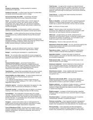
3. Determine wind direction and adjust controls for proper crosswind correction (see Figure 1)<br />
4. Position your feet with your heels on the floor and both feet firmly on the rudder pedals. Do not allow your feet to<br />
rest on the brakes. (See figure 2)<br />
5. If throttle is fully closed, roll throttle to the right 2-3 turns to begin the taxi<br />
6. After the aircraft begins to roll, apply gentle brake pressure to ensure brakes are working properly<br />
7. After the aircraft begins to roll again, power may be reduced to maintain a speed no faster than the appearance of a<br />
brisk walk<br />
8. Apply rudder pressure as needed for directional control to maintain the nose wheel on the centerline (if applicable).<br />
9. Use brakes only when necessary to slow or stop the aircraft<br />
Tolerances<br />
1. Flight controls must be placed properly for the appropriate wind conditions<br />
2. Control must be maintained without excessive use of brakes<br />
3. Compliance with all airport taxiway signs and markings<br />
4. Compliance with all air traffic control instructions or light-gun signals (see figure 3)<br />
5. Must taxi no faster than a brisk walk<br />
6. Must avoid other aircraft and hazards
Taxi<br />
Up aileron on<br />
LH wing and<br />
elevator neutral<br />
(turn into the<br />
wind)<br />
Up aileron on<br />
RH wing and<br />
elevator neutral<br />
(turn into the<br />
wind)<br />
Down elevator and<br />
aileron down on LH<br />
wing (DIVE AWAY<br />
FROM WIND)<br />
Down elevator and<br />
aileron down on LH<br />
wing (DIVE AWAY<br />
FROM WIND)<br />
Signal Aircraft On Surface Aircraft in flight<br />
Steady Green Cleared for takeoff Cleared to Land<br />
Flashing Green Cleared to taxi Return for landing<br />
Steady Red Stop Give way to other<br />
aircraft<br />
Flashing Red Taxi clear of runway<br />
in use<br />
Airport unsafe—do<br />
not land<br />
Flashing White Return to starting<br />
point on airport<br />
Not Applicable<br />
Alternating Red<br />
And Green<br />
Exercise extreme<br />
caution<br />
Exercise extreme<br />
caution<br />
FIGURE 1—PROPER<br />
CROSSWINGD CONTROLS<br />
FIGURE 3—LIGHT-GUN SIGNALS<br />
A FULL DESCRIPTION OF AIRPORT AND<br />
TAXIWAY SIGNS AND MARKINGS CAN BE<br />
FOUND IN THE AERONAUTCIAL<br />
INFORMATION MANUAL (AIM) PAGES 2-3-<br />
1 THROUGH 2-3-14<br />
FIGURE 2—PROPER FEET POSITIONING<br />
A FULL DESCRIPTION OF GROUND<br />
SIGNALMAN HAND SIGNALS CAN BE<br />
FOUND IN THE AERONAUTICAL<br />
INFORMATION MANUAL (AIM) PAGE 4-3-7<br />
( REV 1) <strong>Henderson</strong> <strong>State</strong> <strong>University</strong> : SMAC: <strong>Maule</strong> MXT-7 <strong>Maule</strong> <strong>Student</strong> <strong>Handbook</strong> Page5-3
( REV 1) <strong>Henderson</strong> <strong>State</strong> <strong>University</strong> : SMAC: <strong>Maule</strong> <strong>Maule</strong> <strong>Student</strong> <strong>Handbook</strong> Page5-4<br />
Traffic Patterns (entering and exiting)<br />
Objectives<br />
1. <strong>Student</strong>s will be able identify the different legs of a traffic pattern<br />
2. <strong>Student</strong>s will be able to apply proper traffic pattern departures and entries at an uncontrolled field<br />
Procedures (EXIT)<br />
1. Perform takeoff as prescribed<br />
2. Maintain extended runway centerline until you reach traffic Pattern Altitude (1,000 MSL at M89)<br />
3. Depart either straight ahead OR 45 o in the direction of the traffic pattern (see figure 4)<br />
4. Make appropriate radio communication<br />
5. If the planned departure is to the opposite side of the traffic pattern, complete one of the following:<br />
a. continue straight out until clear of the traffic pattern before turning on course<br />
b. Complete 45 o departure; climb at least 1,000 feet above traffic pattern altitude before turning on course. (see<br />
figure 5)<br />
Procedures (Entry)<br />
1. Perform “Approach Flow” and “Approach Check” prior to entering the traffic pattern<br />
2. Descend to traffic pattern altitude at least 2 nautical miles prior to entry<br />
3. Maneuver the airplane to enter abeam the midpoint of the runway at a 45 o entry to the downwind leg (see figure 6)<br />
4. If approaching from the opposite side of the traffic pattern, over fly the traffic pattern by at least 1,000 feet. Once clear<br />
of the traffic pattern area, descend to traffic pattern altitude and maneuver for 45 o entry to the downwind leg<br />
Tolerances<br />
1. Perform departures and entries as prescribed
Traffic Patterns (Entering and exiting)<br />
45 o<br />
Either depart<br />
straight ahead or<br />
depart 45 o to the<br />
traffic pattern side<br />
of the runway.<br />
45 o<br />
X-Wind<br />
Upwind<br />
Maintain runway<br />
centerline until<br />
you reach Traffic<br />
Pattern Altitude<br />
Depart straight out<br />
or 45 o , climb to<br />
1,000 feet above<br />
Traffic Pattern<br />
Altitude, and then<br />
turn on course.<br />
45 o<br />
Arrive on a 45 o angle<br />
to the downwind leg.<br />
You should enter the<br />
downwind leg at the<br />
midpoint of the field.<br />
Downwind<br />
36<br />
36<br />
FIGURE 4 - EXIT<br />
FIGURE 5 –<br />
DEPARTING TO<br />
THE OPPOSITE<br />
SIDE OF TRAFFIC<br />
PATTERN<br />
36<br />
Base<br />
FIGURE 6 - ENTRY<br />
Final<br />
A FULL DESCRIPTION OF TRAFFIC PATTERN PROCEDURES CAN BE FOUND IN THE<br />
AERONAUTICAL INFORMATION MANUAL PAGES 4-3-2 THROUGH 4-3-3<br />
( REV 1) <strong>Henderson</strong> <strong>State</strong> <strong>University</strong> : SMAC: <strong>Maule</strong> MXT-7 <strong>Maule</strong> <strong>Student</strong> <strong>Handbook</strong> Page5-5
( REV 1) <strong>Henderson</strong> <strong>State</strong> <strong>University</strong> : SMAC: <strong>Maule</strong> <strong>Maule</strong> <strong>Student</strong> <strong>Handbook</strong> Page5-6<br />
Normal and Crosswind Takeoff<br />
Objectives<br />
1. <strong>Student</strong>s will be able to perform and execute a takeoff with or without crosswind conditions that is safe and<br />
conforms to procedures found in the Pilot’s Operating <strong>Handbook</strong>.<br />
Procedures<br />
1. Perform “Before Takeoff Flow” and “Before Takeoff Check”<br />
2. Hold short at the appropriate “Hold Short Lines” (see figure 7)<br />
3. Clear the area by scanning final approach, base leg, runway, opposite final approach, and opposite base leg<br />
4. Make appropriate radio communication<br />
5. Taxi onto the runway and align the aircraft with the centerline<br />
6. Place crosswind control as necessary<br />
7. Apply Takeoff/Go Around (TOGA) Power and monitor engine instruments. If the engine is making 2300-2500 RPM,<br />
<strong>State</strong>, “TOGA POWER CHECKED”. If not, abort takeoff immediately.<br />
8. Apply enough right rudder to maintain centerline and allow airspeed to accelerate<br />
9. As the ground roll commences, monitor the airspeed indicator. When it begins to register, <strong>State</strong>, “AIRSPEED ACTIVE”.<br />
If the airspeed indicator does not register, abort takeoff immediately.<br />
10. As airspeed accelerates, gradually remove the crosswind correction as needed.<br />
11. At 52 knots (V R ), <strong>State</strong>, “ROTATE, 8 Degrees” and smoothly apply back pressure on the controls<br />
12. Continue applying back pressure until a pitch attitude is reached (≈ 8 o ) to allow the aircraft to accelerate to and<br />
maintain its best rate of climb of 78 knots (V Y )<br />
13. Maintain runway centerline throughout climb out, crabbing into the wind as needed (see figure 8)<br />
Tolerances<br />
1. Maintain runway centerline on takeoff roll and throughout climb out<br />
2. Maintain 78 knots (V Y ) +10/-5 knots (Private) +/-5 knots (Commercial)
Normal and Crosswind Takeoff<br />
360 0 010 0<br />
22<br />
Hold Short Here<br />
and visually clear<br />
the area.<br />
Aircraft Ground Track<br />
Crab Angle<br />
Aircraft Heading<br />
WIND<br />
FIGURE 7—HOLD SHORT LINES<br />
FIGURE 8—CRAB ANGLE<br />
A FULL DESCRIPTION OF PROPER RADIO<br />
COMMUNICATIONS CAN BE FOUND IN<br />
THE AERONAUTICAL INFORMATION<br />
MANUAL PAGES 4-2-1 THROUGH 4-2-13<br />
( REV 1) <strong>Henderson</strong> <strong>State</strong> <strong>University</strong> : SMAC: <strong>Maule</strong> MXT-7 <strong>Maule</strong> <strong>Student</strong> <strong>Handbook</strong> Page5-7
( REV 1) <strong>Henderson</strong> <strong>State</strong> <strong>University</strong> : SMAC: <strong>Maule</strong> <strong>Maule</strong> <strong>Student</strong> <strong>Handbook</strong> Page5-8<br />
Normal and Crosswind Landings<br />
Objectives<br />
1. <strong>Student</strong>s will be able to determine wind direction and apply necessary corrections to allow for a stabilized approach<br />
and landing at a specified point on the runway.<br />
Procedures<br />
1. Determine wind direction and enter traffic pattern accordingly for an upwind landing (See “Traffic Pattern -<br />
entering and exiting” on pages 4-5 for more details)<br />
2. Scan for traffic<br />
3. Make appropriate radio communications<br />
4. Determine Landing Point (See Figure 9)<br />
5. Maintain 90 knots (approximately 2200 RPM) on the downwind leg crabbing, if necessary, to parallel the runway<br />
6. At midfield, perform “Landing Flow” and “Landing Check”<br />
7. Abeam the touchdown point, reduce power to approximately 1700 RPM and pitch to maintain 80 knots<br />
8. Confirm you are within the white arc and introduce 24 o Flaps (1 st Notch)<br />
9. Turn to the base leg approximately 45 0 from the landing point and slow to 70 knots<br />
10. Clear the area by scanning the extended final approach, runway, and opposite final approach and opposite base leg<br />
11. Manage power throughout the downwind and base legs so as to be on the proper glide slope when the turn is made<br />
from base to final approach<br />
12. Make turn to final adjusting for wind so as not to undershoot or overshoot the extended centerline of the runway<br />
13. Slow to 61 knots<br />
14. Establish a stabilized descent allowing for wind<br />
15. Restate, “Landing Check Complete”. If the landing flow/check was not previously completed and verified, execute a<br />
go around immediately.<br />
16. Smoothly round out into the flare approximately 10 -15 feet over the ground<br />
17. Bleed off airspeed as to touchdown approaching stall speed<br />
Tolerances<br />
1. Maintains a stabilized descent throughout the final approach to landing<br />
2. Airspeeds +10/-5 knots (Private) +/-5 knots (Commercial)<br />
3. Touches down +400/-0 feet (Private) +200/-0 feet (Commercial) of landing point<br />
4. On touchdown and rollout, the centerline should never be outside of the main wheels
Normal and Crosswind Landing<br />
45 0 from landing point<br />
Verify “Landing<br />
Checklist”<br />
Perform “Landing Flow”<br />
Base Leg—<br />
Slow to 70<br />
knots<br />
1700 RPM<br />
24 0 Flaps<br />
80 knots<br />
Continue climb to TPA.<br />
Turn to downwind at the<br />
appropriate distance<br />
away from runway.<br />
Final Approach—<br />
Slow to 61 knots.<br />
Confirm Landing<br />
Checklist is<br />
complete<br />
22<br />
Designated Landing Points: The beginning of the<br />
Aiming Point Markings (1,000’ markers) is the standard<br />
at M89. Flight instructors may use other points as they<br />
see fit to demonstrate non-standard approaches.<br />
4<br />
Maintain<br />
Runway<br />
Centerline to<br />
300’ below<br />
TPA<br />
FIGURE 9—NORMAL LANDING<br />
A stabilized descent or approach means that airspeed should be maintained and<br />
power should be adjusted as necessary to maintain a constant angle from where<br />
the final descent started until rounding out into the flare. If on a proper stabilized<br />
descent, the aircraft should remain on glide slope throughout the entire approach.<br />
( REV 1) <strong>Henderson</strong> <strong>State</strong> <strong>University</strong> : SMAC: <strong>Maule</strong> MXT-7 <strong>Maule</strong> <strong>Student</strong> <strong>Handbook</strong> Page5-9
Objectives<br />
( REV 1) <strong>Henderson</strong> <strong>State</strong> <strong>University</strong> : SMAC: <strong>Maule</strong> <strong>Maule</strong> <strong>Student</strong> <strong>Handbook</strong> Page5-10<br />
Short Field Takeoff<br />
1. <strong>Student</strong>s will understand and apply how to safely takeoff from a short runway while avoiding a 50 foot obstacle at the end of<br />
the runway.<br />
2. <strong>Student</strong>s will understand how to apply the different uses of various climb speeds to include V X and V Y<br />
Procedures<br />
1. Perform “Before Takeoff Flow” and “Before Takeoff Check”<br />
2. Hold short at the “Hold Short Lines” (see figure 7)<br />
3. Clear the area by scanning final approach, base leg, runway, opposite final approach, and opposite base leg<br />
4. Make appropriate radio communication<br />
5. Taxi onto the runway and align the aircraft with the centerline using ALL of the available runway<br />
6. Apply brakes<br />
7. Apply Takeoff/Go Around (TOGA) Power and monitor engine instruments. If the engine is making 2300-2500 RPM, <strong>State</strong>, “TOGA<br />
POWER CHECKED”. If not, abort takeoff immediately<br />
8. Release Brakes<br />
9. Apply enough right rudder to maintain centerline and allow airspeed to accelerate<br />
10. As the ground roll commences, monitor the airspeed indicator. When it begins to register, <strong>State</strong>, “AIRSPEED ACTIVE”. If the<br />
airspeed indicator does not register, abort takeoff immediately.<br />
11. At 48 knots (V R ), <strong>State</strong>, “ROTATE, 8 Degrees” and smoothly apply back pressure on the controls<br />
12. Continue applying back pressure until a pitch attitude is reached (≈ 8 o ) to allow the aircraft to accelerate to and maintain its best<br />
angle of climb at 65 knots (V X ) (see figure 10)<br />
13. Maintain 65 knots (V X ) until the obstacle is cleared or you reach 100’ AGL.<br />
14. Transition to 78 knots (V Y ) by slightly lowering the nose and SLOWLY reducing the flaps. The flaps should reach 0 0 around the<br />
same time 78 knots (V Y ) is achieved (see figure 10)<br />
15. Set a pitch attitude (≈ 8 o ) to allow the aircraft to maintain 78 knots (V Y )<br />
16. Maintain runway centerline throughout climb out, crabbing into the wind if necessary (see figure 8)<br />
Tolerances<br />
1. Maintain runway centerline on takeoff roll and throughout climb out<br />
2. V X Airspeed +10/-5 knots (Private), +5/-0 knots (Commercial)<br />
3. V Y Airspeed +10/-5 knots (Private), +5/-5 knots (Commercial)
Short Field Takeoff<br />
Slightly lower the nose to accelerate to 78 knots (V Y )<br />
Retract flaps SLOWLY from 24 0 – 0 0 .<br />
Set Pitch attitude to maintain 78 knots (V Y )<br />
Establish Pitch Attitude that<br />
will maintain 65 knots (V X )<br />
Obstacle cleared or<br />
100 Feet AGL<br />
50 FEET<br />
Use all available runway<br />
Hold Brakes<br />
Apply TOGA Power<br />
Monitor Engine Instruments<br />
48 knots (V R )<br />
<strong>State</strong>, “ROTATE”<br />
FIGURE 10<br />
A FULL DESCRIPTION OF V X AND V Y CAN BE FOUND IN THE<br />
JEPPESEN PRIVATE PILOT MANUAL PAGES 8-16 THROUGH 8-19.<br />
( REV 1) <strong>Henderson</strong> <strong>State</strong> <strong>University</strong> : SMAC: <strong>Maule</strong> MXT-7 <strong>Maule</strong> <strong>Student</strong> <strong>Handbook</strong> Page5-11
Objectives<br />
( REV 1) <strong>Henderson</strong> <strong>State</strong> <strong>University</strong> : SMAC: <strong>Maule</strong> <strong>Maule</strong> <strong>Student</strong> <strong>Handbook</strong> Page5-12<br />
Short Field Landing<br />
1. <strong>Student</strong>s will understand how to make the aircraft land and stop in the shortest distance while clearing an obstacle on the<br />
approach end of the runway.<br />
2. <strong>Student</strong>s will understand and apply the concept of a stabilized approach to landing<br />
Procedures<br />
1. Determine wind direction and enter traffic pattern (See “Normal Traffic Pattern” on pages 4-5 for more details) accordingly for<br />
an upwind landing<br />
2. Scan for traffic<br />
3. Make appropriate radio communications<br />
4. <strong>State</strong> location of the obstacle, Landing Point, and Go around point (See Figure 11)<br />
5. Maintain 90 knots (approximately 2200 RPM) on the downwind leg crabbing, if necessary, to parallel the runway<br />
6. At midfield, perform “Landing Flow” and “Landing Check”<br />
7. Abeam the touchdown point, reduce power to approximately 1700 RPM and pitch to maintain 75 knots<br />
8. Confirm you are within the white arc and introduce 24 o Flaps (1 st Notch)<br />
9. Turn to the base leg at a distance approximately 1.5 times the distance used for a normal landing, slow to 65 knots<br />
10. Clear the area by scanning extended final approach, runway, and opposite final approach and opposite base leg<br />
11. Manage power throughout the downwind and base legs so as to be no lower than 500 AGL when the turn is made from base to final<br />
approach<br />
12. Make turn to final adjusting for wind so as not to undershoot or overshoot the extended centerline of the runway<br />
13. Introduce 40 o Flaps (2 nd Notch) and Slow to 52 knots<br />
14. Maintain 500 AGL until the landing point can be seen over the obstacle. If the obstacle is fictitious, maintain 500 AGL until a slightly<br />
steeper than normal approach is achieved.<br />
15. Reduce Power to 1300 - 1500 RPM to establish a stabilized descent allowing for wind<br />
16. Restate, “Landing Check is complete”. If the landing check was not previously completed and verified, execute a go around<br />
immediately.<br />
17. The landing should be firm with little or no floating in ground effect<br />
18. Simulate maximum breaking by Stating, “Maximum Breaking Applied”<br />
Tolerances<br />
1. Airspeed +10/-5 knots (Private), +/-5 knots (Commercial)<br />
2. Touches down +200/-0 feet (Private) +100/-0 feet (Commercial) of landing point
Short Field Landing<br />
Slow to 65 knots<br />
Maintain 500 AGL<br />
Extend Downwind 1.5 times normal<br />
40 o Flaps<br />
Slow to 52 knots<br />
Maintain 500 AGL<br />
until landing point<br />
can be seen over<br />
the obstacle<br />
50 Feet<br />
Abeam Touchdown Point<br />
1700 RPM<br />
24 0 Flaps<br />
75 knots<br />
1300 - 1500 RPM<br />
Maintain a stabilized<br />
descent to the<br />
touchdown point<br />
Touchdown point:<br />
Beginning of Aiming<br />
Point Markings<br />
(1,000’ Markers)<br />
Designated Landing Points: The beginning of the<br />
Aiming Point Markings (1,000’ markers) is the standard<br />
at M89. Flight instructors may use other points as they<br />
see fit to demonstrate non-standard approaches.<br />
FIGURE 11<br />
( REV 1) <strong>Henderson</strong> <strong>State</strong> <strong>University</strong> : SMAC: <strong>Maule</strong> MXT-7 <strong>Maule</strong> <strong>Student</strong> <strong>Handbook</strong> Page5-13
Objectives<br />
( REV 1) <strong>Henderson</strong> <strong>State</strong> <strong>University</strong> : SMAC: <strong>Maule</strong> <strong>Maule</strong> <strong>Student</strong> <strong>Handbook</strong> Page5-14<br />
Soft Field Takeoff<br />
1. <strong>Student</strong>s will understand the proper technique for taxiing and taking off on an unimproved runway.<br />
2. <strong>Student</strong>s will understand the concept of ground effect.<br />
Procedures<br />
1. Perform “Before Takeoff Flow” and “Before Takeoff Check”<br />
2. Hold short at the “Hold Short Lines” (see figure 7).<br />
3. Clear the area by scanning final approach, base leg, runway, opposite final approach, and opposite base leg.<br />
4. Make appropriate radio communication.<br />
5. Taxi onto the runway while maintaining maximum back pressure to keep as much weight as possible off the nose wheel (see figure<br />
12).<br />
6. Align the airplane with the centerline with no braking and apply Takeoff/Go Around (TOGA) Power. If the engine is making 2300-<br />
2500 RPM, <strong>State</strong>, “TOGA POWER CHECKED”. If not, abort takeoff immediately.<br />
7. As the ground roll commences, monitor the airspeed indicator. When it begins to register, <strong>State</strong>, “AIRSPEED ACTIVE”. If the<br />
airspeed indicator does not register, abort takeoff immediately.<br />
8. As the airplane builds speed, reduce back pressure, as needed, to maintain a V Y pitch attitude (see figure 12).<br />
9. With the airplane already at a V Y pitch attitude, it will become airborne at its slowest possible speed. Because of this, the<br />
aircraft needs to be accelerated to a safe airspeed in order to fly out of “Ground Effect”.<br />
10. After the airplane lifts off, adjust pitch to remain in ground effect just above the runway. (see figure 12).<br />
11. While in this state, accelerate to 65 knots (V X ).<br />
12. Establish a V X pitch attitude (≈ 8 o ) to maintain 65 knots in the climb until you reach 100 feet AGL.<br />
13. Transition to 78 knots (V Y ) by slightly lowering the nose and SLOWLY reducing the flaps. The flaps should reach 0 0 around the<br />
same time 78 knots (V Y ) is achieved (see figure 10)<br />
14. Set a pitch attitude to allow the aircraft to maintain 78 knots (V Y )<br />
15. Maintain runway centerline throughout climb out, crabbing into the wind if necessary (Figure 8)<br />
Tolerances<br />
1. Airspeed +10/-5 knots (Private), +/-5 knots (Commercial)<br />
2. Maintain runway centerline on takeoff roll and throughout climb out
Soft Field Takeoff<br />
100’ AGL<br />
GROUND EFFECT<br />
Maintain back<br />
pressure and do<br />
not stop or brake<br />
when taxiing onto<br />
the runway<br />
Maintain enough<br />
back pressure to<br />
keep the nose in<br />
a V Y pitch<br />
attitude<br />
Lift off at the<br />
slowest<br />
possible speed<br />
Level off and<br />
accelerate to<br />
65 knots (V X )<br />
Reduce flaps to 0 0<br />
& transition from<br />
65 knots (V X ) to<br />
78 knots (V Y )<br />
FIGURE 12<br />
A FULL DESCRIPTION OF GROUND<br />
EFFECT CAN BE FOUND IN THE<br />
JEPPESEN PRIVATE PILOT MANUAL,<br />
PAGE 3-18.<br />
( REV 1) <strong>Henderson</strong> <strong>State</strong> <strong>University</strong> : SMAC: <strong>Maule</strong> MXT-7 <strong>Maule</strong> <strong>Student</strong> <strong>Handbook</strong> Page5-15
( REV 1) <strong>Henderson</strong> <strong>State</strong> <strong>University</strong> : SMAC: <strong>Maule</strong> <strong>Maule</strong> <strong>Student</strong> <strong>Handbook</strong> Page5-16<br />
Soft Field Landing<br />
Objectives<br />
1. <strong>Student</strong>s will be able to apply necessary corrections to allow for a stabilized approach and landing on a runway with an<br />
unimproved surface.<br />
Procedures<br />
1. Select runway to be used and enter traffic pattern (See “Normal Traffic Pattern” on pages 4-5 for more details)<br />
2. Scan for traffic<br />
3. Make appropriate radio communications<br />
4. Maintain 85 knots (approximately 2200 RPM) on the downwind leg crabbing, if necessary, to parallel the runway<br />
5. At midfield, perform “Landing Flow” and “Landing Check”<br />
6. Abeam the touchdown point, reduce power to approximately 1700 RPM and pitch to maintain 75 knots<br />
7. Confirm you are within the white arc and introduce 24 o Flaps (1 st Notch)<br />
8. Turn to the base leg approximately 45 0 from the landing point, and slow to 65 knots<br />
9. Clear the area by scanning final approach, runway, and opposite final approach and opposite base leg<br />
10. Manage power throughout the downwind and base legs so as to be on the proper glide slope when the turn is made from<br />
base to final approach<br />
11. Turn to final adjusting for wind so as not to undershoot or overshoot the extended centerline of the runway<br />
12. Introduce 40 o flaps, and slow to 52 knots<br />
13. Establish a stabilized descent allowing for wind<br />
14. Restate, “Landing Check is complete”. If the landing check was not previously completed and verified, execute a go around<br />
immediately.<br />
15. Smoothly round out into the flare approximately 10 -15 feet over the ground<br />
16. Use power throughout the level–off and touchdown to ensure touchdown at the slowest possible airspeed with the<br />
weight fully supported by the wings (See figure 13)<br />
17. Maintain the use of power to transition the aircraft weight from being supported by the wings to being supported by the<br />
wheels. Do not allow the nose to simply “fall” onto the surface, but rather control the nosewheel to the surface to<br />
touchdown as softly as possible.<br />
18. Even after the nosewheel has touched down, maintain back pressure and avoid using brakes.<br />
Tolerances<br />
1. Airspeed +10/-5 knots (Private), +/- 5 knots (Commercial)
Soft Field Landing<br />
Stabilized Descent<br />
Use power throughout the<br />
level–off and touchdown to<br />
ensure touchdown at the<br />
slowest possible airspeed<br />
with the weight fully<br />
supported by the wings<br />
Use power to<br />
transition the aircraft<br />
weight from being<br />
supported by the<br />
wings to being<br />
supported by the<br />
wheels<br />
Transition Area<br />
Ground Effect<br />
FIGURE 13<br />
( REV 1) <strong>Henderson</strong> <strong>State</strong> <strong>University</strong> : SMAC: <strong>Maule</strong> MXT-7 <strong>Maule</strong> <strong>Student</strong> <strong>Handbook</strong> Page5-17
( REV 1) <strong>Henderson</strong> <strong>State</strong> <strong>University</strong> : SMAC: <strong>Maule</strong> <strong>Maule</strong> <strong>Student</strong> <strong>Handbook</strong> Page5-18<br />
Go Around<br />
Objectives<br />
1. <strong>Student</strong>s will understand when to initiate a go around.<br />
2. <strong>Student</strong>s will understand how to transition from landing power, pitch attitude, and configuration to a maximum<br />
performance climb to avoid any obstacles or any other traffic.<br />
Procedures<br />
1. Make a timely decision to discontinue the approach to landing and initiate a go around<br />
2. Apply Takeoff / Go Around (TOGA) power<br />
3. Transition to a V X pitch attitude.<br />
CAUTION: the power along with the likely elevator trim used in landing will cause a rapid increase in pitch. the focus is<br />
controlling the pitch attitude so that a climb is maintained and the airspeed is accelerating to 65 knots if below or<br />
maintaining 65 knots if at or above<br />
4. Set flaps to 24 0 ; If at 0 o flaps, remain at 0 o flaps<br />
5. Once a positive rate of climb has been established, transition to 78 knots (V Y ) by slightly lowering the nose and SLOWLY<br />
reducing the flaps. The flaps should reach 0 0 around the same time 78 knots (V Y ) is achieved (see figure 14)<br />
6. If a go around is performed due to conflicting traffic on the runway, follow steps 1 through 5, and apply a side step<br />
maneuver when a safe altitude is reached. (see figure 15)<br />
7. If no conflicting traffic exists, maintain runway centerline<br />
8. Complete the “Go Around” checklist<br />
9. Maintain TOGA power until traffic pattern altitude is reached<br />
10. Re-enter the traffic pattern and avoid any conflicting traffic<br />
Tolerances<br />
CAUTION: Instructors and students should avoid making any radio calls until aircraft is in a stable climb at a safe<br />
distance above the ground. Remember…aviate, navigate, then communicate!<br />
1. Airspeed +10/- 5 knots (Private), +/- 5 knots (Commercial)
Go Around<br />
Normal Approach to<br />
Landing<br />
Establish V X pitch<br />
attitude, set flaps to 24 0<br />
Positive Rate of<br />
Climb; Flaps 0 0 ,<br />
accelerate to 78<br />
FIGURE 14<br />
Maintain TOGA power until<br />
traffic pattern altitude, and<br />
re-enter the traffic pattern<br />
Traffic Pattern Side<br />
of the Runway<br />
Side step to the opposite side<br />
of the traffic pattern<br />
Establish climb to a safe<br />
maneuvering altitude<br />
Makes Decision to Go Around<br />
FIGURE 15<br />
( REV 1) <strong>Henderson</strong> <strong>State</strong> <strong>University</strong> : SMAC: <strong>Maule</strong> MXT-7 <strong>Maule</strong> <strong>Student</strong> <strong>Handbook</strong> Page5-19
( REV 1) <strong>Henderson</strong> <strong>State</strong> <strong>University</strong> : SMAC: <strong>Maule</strong> <strong>Maule</strong> <strong>Student</strong> <strong>Handbook</strong> Page5-20<br />
Forward Slip to a Landing<br />
Objectives<br />
1. <strong>Student</strong>s will understand the difference between a sideslip and a forward slip.<br />
2. <strong>Student</strong>s will understand when a forward slip to landing should be attempted.<br />
3. <strong>Student</strong>s will be able to apply a forward slip to regain a proper glide path to landing.<br />
Procedures<br />
1. Establish and state point of intended landing<br />
2. Establish final approach speed and configuration (24 0 flaps)<br />
3. Maintain 500 Feet AGL on final until a steeper than normal approach path is achieved<br />
4. Reduce Power to idle<br />
5. Apply aileron and lower the wing in the direction of the wind (if applicable)<br />
6. Simultaneously apply enough rudder pressure in the opposite direction to maintain the proper ground track<br />
7. Due to additional drag, lower the nose to maintain the proper airspeed.<br />
a. CAUTION: The potential for an unintentional stall during a forward slip is increased. Ensure the pitch attitude is<br />
low enough to avoid the potential for a stall.<br />
b. CAUTION: Due to the flight path of the aircraft and the position of the pitot tube, airspeeds could be erroneous.<br />
8. Apply the forward slip control input until the proper glide path is reached<br />
9. Simultaneously remove aileron and rudder input to return to a normal stabilized descent to landing (see figure 16)<br />
Tolerances<br />
1. Touches down within +400/-0 feet of the point of intended landing
Forward Slip to a Landing<br />
Aircraft is in a landing configuration at final approach<br />
airspeed. Maintain 500 AGL until steep descent path is<br />
achieved. Reduce power to idle.<br />
Roll in aileron input into the direction of the wind.<br />
Simultaneously apply opposite rudder to maintain the<br />
proper tracking of the extended centerline.<br />
Due to the increased drag caused by the slip, lower the<br />
nose slightly to maintain the proper final approach<br />
airspeed.<br />
Adjust these control inputs as needed to maintain the<br />
forward slipping condition and aligned with the<br />
centerline until the proper glide slope is achieved.<br />
FIGURE 16<br />
( REV 1) <strong>Henderson</strong> <strong>State</strong> <strong>University</strong> : SMAC: <strong>Maule</strong> MXT-7 <strong>Maule</strong> <strong>Student</strong> <strong>Handbook</strong> Page5-21
( REV 1) <strong>Henderson</strong> <strong>State</strong> <strong>University</strong> : SMAC: <strong>Maule</strong> <strong>Maule</strong> <strong>Student</strong> <strong>Handbook</strong> Page5-22<br />
Steep Turns<br />
Objectives<br />
1. <strong>Student</strong>s will develop smooth control and coordination in steep angles of bank<br />
2. <strong>Student</strong>s will understand control inputs necessary for a steep banked turn<br />
3. <strong>Student</strong>s will understand and apply the effects of over-banking tendency (Refer to figure 17)<br />
4. <strong>Student</strong>s will understand why back elevator pressure is needed in a turn<br />
5. <strong>Student</strong>s will understand the concept of load factor (Refer to Figure 18)<br />
Procedures<br />
1. Start at an altitude so that the entire maneuver can be completed above 1,500 feet AGL<br />
2. Perform over suitable field in case of emergency<br />
3. Begin with a power setting of 2300 RPM. Note the airspeed that results from this power setting as the entry speed. This<br />
speed should be maintained throughout the maneuver.<br />
4. Perform clearing turns (two 90 o turns in opposite directions or one 180 o turn)<br />
5. Align the longitudinal axis of the aircraft with field section lines or select an outside reference point to begin the turn<br />
(The point should be prominent and the closer to the horizon the better). When aligned with the reference point, note the<br />
corresponding heading.<br />
6. Smoothly, roll into a coordinated 45 0 (private), 50 0 (commercial) bank in either direction (The appropriate angle of bank<br />
should be reached well within the first 90 0 of the turn)<br />
7. When rolling in the bank, apply approximately 100 - 200 RPM (3 to 4 rolls of the throttle) to maintain the target airspeed<br />
8. Continue the turn for 360 0 (During the 360 0 turn, the use of outside visual reference with the horizon is essential)<br />
9. roll out on the previously selected outside reference and corresponding heading.<br />
10. After one turn is completed,<br />
o you may reconfigure the airplane for a turn in the opposite direction (private)<br />
o it must be IMMEDIATELY followed by a turn in the opposite direction (commercial)<br />
11. Repeat steps 6 through 8 for a turn in the opposite direction<br />
Tolerances<br />
1. Altitude +/- 100 feet<br />
2. Airspeed +/- 10 knots<br />
3. Bank +/- 5 0<br />
4. Heading +/- 10 0 on the rollout
Steep Turns<br />
Path of the Inside<br />
wing travels a<br />
shorter distance<br />
Path of the<br />
Outside wing<br />
must travel a<br />
farther distance<br />
Lift = 2,000 lbs<br />
Weight = 2,000 lbs<br />
Vertical Lift = 2,000 lbs<br />
45 0<br />
Total lift = 2,829 lbs.<br />
This is the total lift<br />
the airplane has to<br />
create to maintain<br />
altitude at 45 0 bank.<br />
Over-banking Tendency<br />
Because the outside wing travels farther<br />
than the inside wing, it must also travel<br />
faster. The faster an airfoil travels the more<br />
lift it produces. This causes the airplane to<br />
“want” to continue to increase bank.<br />
FIGURE 17<br />
Centripetal force<br />
= 2,000 lbs. Will<br />
always be equal<br />
to horizontal lift.<br />
Resultant Load<br />
(AKA Load<br />
Factor) = 2,829<br />
lbs. Will always<br />
be equal to<br />
Total Lift<br />
Weight = 2,000 lbs<br />
FIGURE 18<br />
Horizontal Lift =<br />
2,000 lbs. This is<br />
the force that<br />
makes the<br />
airplane turn.<br />
For greater detail,<br />
see page 3-56 of<br />
the Jeppessen<br />
Private Pilot Text<br />
( REV 1) <strong>Henderson</strong> <strong>State</strong> <strong>University</strong> : SMAC: <strong>Maule</strong> MXT-7 <strong>Maule</strong> <strong>Student</strong> <strong>Handbook</strong> Page5-23
Objectives<br />
( REV 1) <strong>Henderson</strong> <strong>State</strong> <strong>University</strong> : SMAC: <strong>Maule</strong> <strong>Maule</strong> <strong>Student</strong> <strong>Handbook</strong> Page5-24<br />
Rectangular Course<br />
1. <strong>Student</strong>s will understand how to determine wind direction.<br />
2. <strong>Student</strong>s will apply the effects of wind direction and speed on ground track by making a circuit around a field while maintaining a<br />
constant distance from the field boundaries.<br />
3. <strong>Student</strong>s will correlate the application of this maneuver to flight in a traffic pattern.<br />
Procedures<br />
1. Start at an altitude so that the entire maneuver can be completed between 600 - 1000 feet AGL (around 1,000 MSL works great<br />
around M89)<br />
2. Perform over suitable field in case of emergency<br />
3. Select a square or rectangular field or an area bounded on four sides by section lines, trees, or roads. (The sides should be<br />
approximately 1 mile in length)<br />
4. Determine Wind Direction by identifying smoke or by performing a wind circle (see figure 19)<br />
5. Begin with a power setting of 2300 RPM. Note the airspeed that results from this power setting as the entry speed. This speed<br />
should be maintained throughout the maneuver.<br />
6. Perform clearing turns (two 90 o turns in opposite directions or one 180 o turn)<br />
7. Enter the maneuver on a 45 o degree to the downwind leg at the approximate midpoint of the field (see figure 20)<br />
8. At an appropriate distance (one quarter to one half mile) away from the field, turn onto the downwind leg.<br />
9. Start the turn abeam the corner of the field boundaries. Since you are turning from the downwind leg, your groundspeed is at its<br />
highest. Because of this, the turn should result in the steepest bank (the steepness of the bank will be determined by the distance<br />
you are maintaining from the field and the velocity of the wind)<br />
10. Continue on the crosswind leg. Since the wind is blowing you away from the field, you need to crab into the wind to maintain a<br />
constant distance away from the field. You accomplish this by holding a heading that is slightly into the wind<br />
11. Start the next turn abeam the corner of the field boundaries. Since you are turning from a crosswind, your groundspeed is<br />
average. Because of this, the turn should result in an average bank. (the steepness of the bank will be determined by the<br />
distance you are maintaining from the field and the velocity of the wind)<br />
12. Continue on the upwind leg. You should not need much crab angle to maintain a constant distance since you are traveling into the<br />
wind.<br />
13. Start the next turn abeam the corner of the field boundaries. Since you are turning from an upwind, your groundspeed is at its<br />
slowest. Because of this, the turn should result in the shallowest bank. (the steepness of the bank will be determined by the<br />
distance you are maintaining from the field and the velocity of the wind)<br />
14. Continue on the crosswind leg. Since the wind is blowing you into the field, you need to crab into the wind to maintain a constant<br />
distance away from the field. You accomplish this by holding a heading that is slightly into the wind<br />
15. Start the next turn abeam the corner of the field boundaries. Since you are turning from a crosswind, your groundspeed is<br />
average. Because of this, the turn should result in an average bank. (the steepness of the bank will be determined by the<br />
distance you are maintaining from the field and the velocity of the wind)<br />
16. Terminate the maneuver by departing on a 45 o from the downwind leg at the midpoint of the field.<br />
Tolerances<br />
1. Altitude +/- 100 feet<br />
2. Airspeed +/- 10 knots<br />
3. Maintains a constant distance from the field
RECTANGULAR COURSE<br />
Crab into the wind<br />
WIND<br />
WIND<br />
Start turns<br />
abeam the<br />
corners<br />
WIND<br />
WIND<br />
Slowest Groundspeed<br />
WIND<br />
Fastest Groundspeed<br />
Begin a wind circle by positioning yourself directly over an<br />
intersection or prominent point. Complete a 360 o turn with a<br />
constant rate of turn and determine where the wind is coming<br />
from by where you are after the 360 o turn.<br />
Crab into the wind<br />
FIGURE 19 – Wind Circle<br />
FIGURE 20 – Rectangular Course<br />
( REV 1) <strong>Henderson</strong> <strong>State</strong> <strong>University</strong> : SMAC: <strong>Maule</strong> MXT-7 <strong>Maule</strong> <strong>Student</strong> <strong>Handbook</strong> Page5-25
Objectives<br />
( REV 1) <strong>Henderson</strong> <strong>State</strong> <strong>University</strong> : SMAC: <strong>Maule</strong> <strong>Maule</strong> <strong>Student</strong> <strong>Handbook</strong> Page5-26<br />
S-Turns Across a Road<br />
1. <strong>Student</strong>s will understand how to determine wind direction.<br />
2. <strong>Student</strong>s will apply the effects of wind direction and speed on ground track by making two semicircles of equal distance on<br />
each side of a selected straight line on the ground.<br />
Procedures<br />
1. Start at an altitude so that the entire maneuver can be completed between 600 - 1000 feet AGL (around 1,000 MSL works great<br />
around M89)<br />
2. Perform over suitable field in case of emergency<br />
3. Determine Wind Direction by identifying smoke or by performing a wind circle (see figure 19)<br />
4. Select a straight line perpendicular to the wind direction (If the wind is from the south, find a straight line running east and<br />
west). The straight line can be a road, fence, railroad, or section line that is a minimum of 1 mile in length.<br />
5. Begin with a power setting of 2300 RPM. Note the airspeed that results from this power setting as the entry speed. This speed<br />
should be maintained throughout the maneuver.<br />
6. Perform clearing turns (two 90 o turns in opposite directions or one 180 o turn)<br />
7. Enter the maneuver downwind<br />
8. As soon as you cross the straight line, begin a turn to the right or left (whichever is needed) to begin the maneuver.<br />
9. Remember that the amount of bank you must input is a direct correlation to your groundspeed. The faster the groundspeed, the<br />
greater amount of bank you must input.<br />
10. The first semicircle will begin with a steep bank (your groundspeed is at its greatest). As you begin to reach the 90 o point of the<br />
turn, the bank will need to be reduced to a relatively moderate bank (your groundspeed has been reduced). As you continue the<br />
turn back to the straight line, your bank will continually decrease to 0 o as you cross the straight line (you are turning into the<br />
wind, so your groundspeed is continually decreasing). (See figure 21)<br />
11. The second semicircle will begin immediately following the first. The second semicircle will start with a shallow bank (Your<br />
groundspeed is at its slowest). As you begin to reach the 90 o point of the turn, the bank will need to be increased to a relatively<br />
moderate bank (your groundspeed is beginning to increase). As you continue the turn back to the straight line, your bank will<br />
increase enough to cross the straight line perfectly perpendicular to it.<br />
Tolerances<br />
1. Altitude +/- 100 feet<br />
2. Airspeed +/- 10 knots<br />
3. Applies adequate wind drift direction to track a constant radius turn on each side of the selected straight line.
S-Turns<br />
WIND<br />
Approaching Reference Line<br />
Bank will be continue to<br />
decrease to 0 o as you reach<br />
the reference line<br />
Over Reference Line<br />
Bank will be at 0 o and you should be<br />
perpendicular to the line as you cross.<br />
90 o point<br />
Bank will be reduced to a<br />
moderate bank. Notice distance<br />
away from reference line.<br />
START<br />
Steep bank.<br />
Groundspeed is<br />
at its fastest.<br />
Approaching Reference Line<br />
Bank will continue to<br />
increase as groundspeed<br />
increases.<br />
START<br />
Start immediately<br />
after completing<br />
first turn. Shallow<br />
Bank. Groundspeed<br />
is at its slowest.<br />
90 o point<br />
Bank will be increased to a<br />
moderate bank. Notice distance<br />
away from reference line. It<br />
should be the same as the first.<br />
ENTRY<br />
Enter the<br />
maneuver<br />
downwind.<br />
FIGURE 21—S-Turns<br />
( REV 1) <strong>Henderson</strong> <strong>State</strong> <strong>University</strong> : SMAC: <strong>Maule</strong> MXT-7 <strong>Maule</strong> <strong>Student</strong> <strong>Handbook</strong> Page5-27
Objectives<br />
( REV 1) <strong>Henderson</strong> <strong>State</strong> <strong>University</strong> : SMAC: <strong>Maule</strong> <strong>Maule</strong> <strong>Student</strong> <strong>Handbook</strong> Page5-28<br />
Turns around a Point<br />
1. <strong>Student</strong>s will understand how to determine wind direction.<br />
2. <strong>Student</strong>s will apply the effects of wind direction and speed on ground track by making at least two complete circles of uniform<br />
distance from a prominent ground reference point.<br />
Procedures<br />
1. Start at an altitude so that the entire maneuver can be completed between 600 - 1000 feet AGL (around 1,000 MSL works great<br />
around M89)<br />
2. Perform over suitable field in case of emergency<br />
3. Determine Wind Direction by identifying smoke or by performing a wind circle (see figure 19)<br />
4. Select a prominent ground reference point (intersections or isolated trees work great; do not pick points that are too large or<br />
homes or buildings)<br />
5. Begin with a power setting of 2300 RPM. Note the airspeed that results from this power setting as the entry speed. This speed<br />
should be maintained throughout the maneuver.<br />
6. Perform clearing turns (two 90 o turns in opposite directions or one 180 o turn)<br />
7. Enter the maneuver downwind approximately ½ mile away from the point<br />
8. Begin the turn when abeam the reference point<br />
9. Remember that the amount of bank you must input is a direct correlation to your groundspeed. The faster the groundspeed, the<br />
greater amount of bank you must input.<br />
10. The amount of bank you must input will constantly change throughout the maneuver, but for the purposes of this lesson plan,<br />
the circle will be broken into four sections:<br />
a. Section 1 (first 90 o )—Steepest bank; Groundspeed will be the fastest<br />
b. Section 2 (Second 90 o )—Shallower Bank; Groundspeed will begin to slow as you go from a crosswind to a headwind<br />
c. Section 3 (Third 90 o )—Shallowest Bank; Groundspeed will be the slowest<br />
d. Section 4 (Fourth 90 o )—Steeper Bank; Groundspeed will begin to quicken as you go from a crosswind to a tailwind<br />
11. Complete this circuit at least twice.<br />
Tolerances<br />
1. Altitude +/- 100 feet<br />
2. Airspeed +/- 10 knots<br />
3. Applies adequate wind drift direction to track a constant radius turn on around the selected reference point.
Turns around a Point<br />
Shallower<br />
Bank<br />
Shallowest<br />
Bank<br />
Steeper<br />
Bank<br />
Steepest<br />
Bank<br />
ENTRY<br />
Enter the<br />
maneuver<br />
downwind<br />
WIND<br />
FIGURE 22—Turns around a point<br />
( REV 1) <strong>Henderson</strong> <strong>State</strong> <strong>University</strong> : SMAC: <strong>Maule</strong> MXT-7 <strong>Maule</strong> <strong>Student</strong> <strong>Handbook</strong> Page5-29
( REV 1) <strong>Henderson</strong> <strong>State</strong> <strong>University</strong> : SMAC: <strong>Maule</strong> <strong>Maule</strong> <strong>Student</strong> <strong>Handbook</strong> Page5-30<br />
Slow Flight<br />
Objectives<br />
1. <strong>Student</strong>s will understand flight characteristics and controllability of an airplane at slow airspeeds.<br />
2. <strong>Student</strong>s will correlate the concepts of flight at various airspeeds and configurations to the traffic pattern.<br />
Procedures<br />
1. Start at an altitude so that the entire maneuver can be completed above 1,500 feet AGL<br />
2. Perform over suitable field in case of emergency<br />
3. Begin with a power setting of 2300 RPM.<br />
4. Perform clearing turns (two 90 o turns in opposite directions or one 180 o turn)<br />
5. Begin the maneuver on a cardinal heading (N, S, E, W) or as specified by the instructor or examiner<br />
6. Reduce power to approximately 1700 RPM<br />
7. When power is reduced, you must increase back pressure in order to maintain altitude<br />
8. When power is reduced and back pressure is added, the airplane will begin to slow<br />
9. Slow the aircraft to 60 knots; as you approach 60 knots, power will need to be added slightly (approximately 1900 RPM)<br />
in order to maintain altitude and airspeed. From this point forward, remember that both pitch and power must be used in<br />
conjunction with one another in order to maintain altitude and airspeed.<br />
10. Once the aircraft is stable at 60 knots, perform a 90 o turn in either direction or as specified by the instructor or<br />
examiner. Use a standard rate turn or about 10-15 o bank to complete the turn.<br />
11. Introduce 24 o Flaps (1 st notch), slow to 50 knots. Manage pitch or power as necessary<br />
12. Once the aircraft is stable at 50 knots, perform a 90 o turn in either direction or as specified by the instructor or<br />
examiner. Use a standard rate turn or about 10-15 o bank to complete the turn.<br />
13. Introduce 40 o Flaps (2 nd notch), slow to approximately 40 knots. This should be an airspeed at which any further increase<br />
in angle of attack or load factor, or reduction in power will cause an immediate stall. Manage pitch or power as<br />
necessary<br />
14. Once the aircraft is stable at 40 knots, perform a 90 o turn in either direction or as specified by the instructor or<br />
examiner. Use a standard rate turn or about 10-15 o bank to complete the turn.<br />
*This is the standard way of performing this maneuver, but Instructors or examiners may add or substitute climbs or<br />
descents at any airspeed or configuration<br />
15. Recovery:<br />
a. On many occasions recovery will be accomplished through the completion of a Power Off Stall (Discussed on page 32)<br />
b. If a power off stall is not performed, recover in the following manner:<br />
i. Apply full throttle<br />
ii. Allow aircraft to accelerate to 50 knots, then reduce flaps to 24 o Flaps<br />
iii. Maintain altitude and allow the airplane to accelerate to 65 knots (V X )<br />
iv. Reduce flaps to 0 o , maintain altitude, and accelerate to cruise<br />
v. Reduce power to 2200-2300 RPM<br />
Tolerances<br />
1. Altitude +/- 100 feet (Private), +/- 50 feet (Commercial)<br />
2. Airspeed +10/-0 knots (Private), +5/-0 (Commercial)<br />
3. Bank +/- 10 o (Private), +/- 5 0 (Commercial)<br />
4. Heading +/- 10 0 (Private & Commercial)
Slow Flight<br />
Recovery (other than Power Off Stall)<br />
Full Throttle; Maintain altitude;<br />
Accelerate to 50 knots; Flaps to 24 o ;<br />
Accelerate to 65 knots; Flaps to 0 o ;<br />
Return to Cruise<br />
Introduce 40 o Flaps<br />
(2 nd Notch)<br />
Slow to ~40 knots.<br />
Manage power and<br />
pitch as necessary<br />
ENTRY<br />
Power ~1700 RPM<br />
Pitch to maintain altitude;<br />
Slow to 60 knots; Increase<br />
power as necessary (~1900<br />
RPM) to maintain altitude<br />
Introduce 24 o Flaps (1 st Notch)<br />
Slow to 50 knots. Manage<br />
power and pitch as necessary.<br />
FIGURE 23—Slow Flight<br />
( REV 1) <strong>Henderson</strong> <strong>State</strong> <strong>University</strong> : SMAC: <strong>Maule</strong> MXT-7 <strong>Maule</strong> <strong>Student</strong> <strong>Handbook</strong> Page5-31
( REV 1) <strong>Henderson</strong> <strong>State</strong> <strong>University</strong> : SMAC: <strong>Maule</strong> <strong>Maule</strong> <strong>Student</strong> <strong>Handbook</strong> Page5-32<br />
Power Off Stalls<br />
Objectives<br />
1. <strong>Student</strong>s will understand when and why a power off stall occurs<br />
2. <strong>Student</strong>s will understand how to recognize an approaching stall<br />
3. <strong>Student</strong>s will understand spin avoidance techniques<br />
4. <strong>Student</strong>s will apply proper recovery techniques to recover from a stall in the least amount of altitude loss possible<br />
Procedures<br />
1. Start at an altitude so that the entire maneuver can be completed above 1,500 feet AGL<br />
2. Perform over suitable field in case of emergency<br />
3. Begin with a power setting of 2300 RPM.<br />
4. Perform clearing turns (two 90 o turns in opposite directions or one 180 o turn)<br />
5. Begin the maneuver on a cardinal heading (N, S, E, W) or as specified by the instructor or examiner<br />
6. Reduce power to approximately 1700 RPM<br />
7. When airspeed is within the white arc (flap operating range), introduce 40 o Flaps<br />
8. If performing at the completion of slow flight, begin procedures here:<br />
9. Slowly reduce power to idle (Keep hand on throttle)<br />
10. Continuously add back pressure to maintain altitude and allow airspeed to decrease until the critical angle of attack is<br />
breached and the airplane’s wing stalls.<br />
*This is the standard way of performing this maneuver, but Instructors or examiners may add or substitute turns or<br />
descents for entry to the stall*<br />
11. Recovery:<br />
a. Simultaneously lower nose (the horizon should be about half way up the windshield) and apply full throttle<br />
b. Once the stall is broken, return the nose to a V X pitch attitude<br />
c. Reduce flaps to 24 o<br />
d. Maintain 65 knots (V X ) until you have established a positive rate of climb and climb back to the altitude at the point of<br />
stall or an altitude as assigned<br />
e. Reduce flaps to 0 o , Climb at V Y , if necessary<br />
f. Return to Cruise<br />
Tolerances<br />
1. Altitude: Least amount of loss possible<br />
2. Bank +/- 10 o (Private), +/- 5 0 (Commercial)<br />
3. Heading +/- 10 0 (Private & Commercial)
Power Off Stalls<br />
Power to 1700 RPM;<br />
40 o flaps<br />
Reduce Power to<br />
Idle; Increase pitch<br />
attitude until the<br />
stall occurs<br />
Simultaneously lower<br />
nose and add full<br />
power. Once stall is<br />
broken, return to V X<br />
pitch attitude<br />
Reduce flaps to 24 o ;<br />
establish a positive<br />
rate of climb; Flaps<br />
to 0 o ; Level off.<br />
Relationship of Angle of Attack and Stalls<br />
You can see in the chart that as angle of<br />
attack increases lift also increases. That<br />
is, until it reaches its critical angle. For<br />
this airfoil, the critical angle is 17 o . At<br />
this angle, airflow has separated from the<br />
wing and the wing can no longer create<br />
lift (See the third picture).<br />
FIGURE 24—Power off stalls<br />
( REV 1) <strong>Henderson</strong> <strong>State</strong> <strong>University</strong> : SMAC: <strong>Maule</strong> MXT-7 <strong>Maule</strong> <strong>Student</strong> <strong>Handbook</strong> Page5-33
( REV 1) <strong>Henderson</strong> <strong>State</strong> <strong>University</strong> : SMAC: <strong>Maule</strong> <strong>Maule</strong> <strong>Student</strong> <strong>Handbook</strong> Page5-34<br />
Power On Stalls<br />
Objectives<br />
1. <strong>Student</strong>s will understand when and why a power on stall occurs<br />
2. <strong>Student</strong>s will understand how to recognize an approaching stall<br />
3. <strong>Student</strong>s will understand spin avoidance techniques<br />
4. <strong>Student</strong>s will apply proper recovery techniques to recover from a stall in the least amount of altitude loss possible<br />
Procedures<br />
1. Start at an altitude so that the entire maneuver can be completed above 1,500 feet AGL<br />
2. Perform over suitable field in case of emergency<br />
3. Begin with a power setting of 2300 RPM.<br />
4. Perform clearing turns (two 90 o turns in opposite directions or one 180 o turn)<br />
5. Begin the maneuver on a cardinal heading (N, S, E, W) or as specified by the instructor or examiner<br />
6. Reduce power to approximately 1500 RPM<br />
7. Increase pitch attitude to maintain altitude<br />
8. Slow to approximate rotation speed (V R = 52 knots)<br />
9. Increase power to 2200 RPM (This setting is used to simulate full power)<br />
10. As power is being increased, begin to pitch up.<br />
11. Continuously add back pressure until the critical angle of attack is breached and the airplane’s wing stalls.<br />
*This is the standard way of performing this maneuver, but Instructors or examiners may add or substitute turns for<br />
entry to the stall*<br />
12. Recovery:<br />
a. lower nose (the horizon should be about half way up the windshield)<br />
b. Once the stall is broken, return the nose to a V Y pitch attitude<br />
c. Maintain 78 knots (V Y ) until you have established a positive rate of climb<br />
d. Return to Cruise<br />
Tolerances<br />
1. Altitude: Least amount of loss possible<br />
2. Bank +/- 10 o (Private), +/- 5 0 (Commercial)<br />
3. Heading +/- 10 0 (Private & Commercial)
Power On Stalls<br />
Power to 1500 RPM;<br />
Slow to V R = 52<br />
knots<br />
Apply simulated full<br />
power (2200 RPM);<br />
continuously pitch<br />
up until the wing<br />
stalls<br />
Lower the nose.<br />
Once stall is broken,<br />
return nose to V Y<br />
pitch attitude<br />
Establish a positive<br />
rate of climb; Level<br />
off.<br />
FIGURE 25—Power on stalls<br />
SPIN RECOVERY TECHNIQUES<br />
When practicing stalls, anti-spin techniques should be used<br />
at all times. THIS AIRCRAFT IS NOT APPROVED FOR<br />
SPINS. UNDER NO CIRCUMSTANCES SHOULD A MAULE BE<br />
ENTERED INTO A SPIN INTENTIONALLY. Should a spin be<br />
inadvertently entered, use these techniques to recover<br />
from the spin.<br />
1. Reduce the power to idle<br />
2. Position the ailerons to neutral<br />
3. Apply full opposite rudder against the<br />
rotation<br />
4. Apply a positive and brisk, straight forward<br />
movement of the elevator control forward of<br />
the neutral to break the stall<br />
5. After the spin rotation stops, neutralize the<br />
rudder<br />
6. Begin applying back elevator pressure to<br />
raise the nose to level flight.<br />
( REV 1) <strong>Henderson</strong> <strong>State</strong> <strong>University</strong> : SMAC: <strong>Maule</strong> MXT-7 <strong>Maule</strong> <strong>Student</strong> <strong>Handbook</strong> Page5-35
( REV 1) <strong>Henderson</strong> <strong>State</strong> <strong>University</strong> : SMAC: <strong>Maule</strong> <strong>Maule</strong> <strong>Student</strong> <strong>Handbook</strong> Page5-36<br />
Emergency Approach and Landing<br />
(from altitude)<br />
Objectives<br />
1. <strong>Student</strong>s will develop judgment, planning, and procedures when little or no power is available.<br />
2. <strong>Student</strong>s will develop confidence in emergency situations<br />
Procedures<br />
1. Instructors or examiners should ensure the area is clear of traffic and obstacles before initiating this maneuver<br />
2. Instructors or examiners should initiate this maneuver by retarding the throttle to idle, and stating, “Simulated<br />
Emergency Landing”<br />
3. Instructors or Examiners should clear the throttle periodically to ensure safe operation of the engine. At a minimum,<br />
this should occur every 1,000 feet.<br />
4. <strong>Student</strong>s should immediately complete the emergency flow<br />
a. A—Airspeed; pitch to establish best glide speed (72 knots)<br />
b. L—Landing Site; Pick a suitable landing site; Determine wind direction; Determine plan of action for descent and<br />
landing<br />
c. A—Attempt Restart; Flow right to left (mixture rich, carburetor heat on, fuel pump on, mags on both, primer in and<br />
locked, fuel on fullest tank or both)<br />
d. R—Radios; set radio frequency to nearest airport or emergency frequency (121.50)<br />
e. M—Mayday; Make distress call with accurate location<br />
f. S—Secure; Seatbelts, Mixture Lean (simulated), Mags off (simulated), Fuel Selector off (simulated), Crack Door<br />
(simulated)<br />
5. If time allows, perform checklist<br />
6. Once the landing site is determined, immediately turn towards a point abeam your touchdown point at a distance where a<br />
downwind leg would be located. This point is known as the “key point”.<br />
7. Once over the key point, make one of two decisions based on your altitude<br />
a. Altitude 1,000 to 1,500 AGL—Continue by entering the downwind<br />
b. Altitude Above 1,500 AGL—Spiral over the key point until you reach 1,000 to 1,500 AGL, then enter the downwind<br />
8. From the downwind leg, monitor your altitude and descent rate to determine when to turn to the base leg. Plan your<br />
descent to touchdown around the middle of the field.<br />
9. When the gliding distance is assured to reach the middle of the field, introduce flaps and/or slip to be able to<br />
touchdown in the first third of the field.<br />
10. Instructors or examiners will instruct a go around at the appropriate time. <strong>Student</strong>s should perform a go around as<br />
prescribed on pages 18-19.<br />
11. Instructors should only allow flight below 500’ AGL if the field is assured and the aircraft will not come within 500 feet<br />
of any person, vessel, vehicle, or structure.<br />
12. Unless a landing will be performed on a runway, Instructors should at no point allow flight below 200’ AGL.<br />
Tolerances<br />
1. Airspeed +/-10 Knots<br />
2. Selects a suitable landing area
Emergency Approach and Landing<br />
(from altitude)<br />
After one spiral, notice how<br />
much altitude is lost to<br />
determine how many more turns<br />
you need to execute<br />
Fly to the key point. Once above the<br />
key point, perform a spiral above the<br />
point to lose altitude (if necessary).<br />
When the landing<br />
point is assured,<br />
introduce flaps<br />
and/or slip to land in<br />
the first third of the<br />
field<br />
Break out from the spiral at 1,000 -<br />
1,500 AGL to set up for a downwind<br />
to the landing site.<br />
WIND<br />
This is a standard way of performing an emergency approach and landing, but all emergencies are different. Use your judgment<br />
and decision making skills to determine a plan of action that best suits the situation at hand.<br />
FIGURE 26—Emergency approach and landing from altitude<br />
( REV 1) <strong>Henderson</strong> <strong>State</strong> <strong>University</strong> : SMAC: <strong>Maule</strong> MXT-7 <strong>Maule</strong> <strong>Student</strong> <strong>Handbook</strong> Page5-37
( REV 1) <strong>Henderson</strong> <strong>State</strong> <strong>University</strong> : SMAC: <strong>Maule</strong> <strong>Maule</strong> <strong>Student</strong> <strong>Handbook</strong> Page5-38<br />
Emergency Approach and Landing<br />
(from the traffic pattern)<br />
Objectives<br />
1. <strong>Student</strong>s will develop judgment, planning, and procedures when little or no power is available in the traffic pattern.<br />
2. <strong>Student</strong>s will develop confidence in emergency situations<br />
Procedures<br />
1. Instructors or examiners should ensure the area is clear of traffic and obstacles before initiating this maneuver<br />
2. Instructors or examiners should initiate this maneuver by retarding the throttle to idle, and stating, “Simulated<br />
Emergency Landing”<br />
3. An engine failure in the traffic pattern is much different than at altitude because there is much less time and altitude.<br />
Because of this, pitch for best glide speed (72 knots) and follow the following procedures depending on your location<br />
within the traffic pattern. If time allows, touchdown should be made with full flaps at the slowest possible speed in<br />
order to maximize chances of survival.<br />
a. Upwind (Liftoff to Crosswind)—Pitch down to maintain the proper speed and land straight ahead<br />
b. Crosswind—Scan 45 o to either side to determine best landing site and land straight ahead. DO NOT ATTEMPT TO MAKE<br />
IT BACK TO THE RUNWAY.<br />
c. Downwind to midfield—You may be able to make it back to the runway at this point. You will need to perform a tailwind<br />
landing in order to make the runway.<br />
d. Midfield downwind to base—turn immediately toward the runway. Adjust the path as necessary to make the runway.<br />
e. Base—Turn immediately toward the runway. Adjust the path as necessary to make the runway. In most cases, even if<br />
you are not able to make the runway, airports will often have clearways with little to no obstructions.<br />
f. Final—Land straight ahead<br />
Tolerances<br />
1. Airspeed +/-10 Knots<br />
2. Makes appropriate decision
Emergency Approach and Landing<br />
(from the traffic pattern)<br />
4<br />
3<br />
5<br />
2<br />
6<br />
1<br />
1<br />
2<br />
3<br />
4<br />
5<br />
6<br />
If engine is<br />
lost here,<br />
land straight<br />
ahead<br />
If engine is lost here, land<br />
straight ahead within 45 o of<br />
your path<br />
If engine is lost here, set up<br />
for a tailwind landing.<br />
If engine is lost here, turn<br />
toward the runway<br />
immediately to land upwind<br />
If engine is lost here,<br />
turn towards the<br />
runway.<br />
If engine is<br />
lost here,<br />
land straight<br />
ahead<br />
FIGURE 27—Emergency approach and landing (from the traffic pattern)<br />
( REV 1) <strong>Henderson</strong> <strong>State</strong> <strong>University</strong> : SMAC: <strong>Maule</strong> MXT-7 <strong>Maule</strong> <strong>Student</strong> <strong>Handbook</strong> Page5-39
( REV 1) <strong>Henderson</strong> <strong>State</strong> <strong>University</strong> : SMAC: <strong>Maule</strong> <strong>Maule</strong> <strong>Student</strong> <strong>Handbook</strong> Page5-40<br />
Power Off 180 o Accuracy Approach<br />
and Landing<br />
Objectives<br />
1. <strong>Student</strong>s will develop judgment and procedures necessary for accurately flying the airplane, without power, to a safe<br />
landing.<br />
2. <strong>Student</strong>s will develop confidence in emergency situations<br />
Procedures<br />
1. Enter the traffic pattern in a normal manner.<br />
2. The standard for the touchdown point will be the beginning of the aiming point markers (1,000’ Markers). Instructors or<br />
examiners may use different touchdown points to illustrate different types of approaches.<br />
3. Perform “Before Landing” checklist<br />
4. Abeam the touchdown point, retard throttle to idle and begin the power off approach<br />
5. Pitch for best glide speed (72 knots)<br />
6. Pay close attention to wind speeds and sink rate to determine the distance away from the landing point you should begin<br />
the turn to the base leg.<br />
7. Introduce flaps as necessary throughout the base and final legs. Landing may be accomplished with 24 o or 40 o flaps.<br />
8. As flaps are introduced adjust airspeed as necessary.<br />
a. 24 o flaps—hold 60 knots<br />
b. 40 o flaps—hold 55 knots<br />
9. Touchdown in as normal landing attitude. DO NOT REDUCE FLAPS IN ORDER TO TOUCHDOWN.<br />
Tolerances<br />
1. Touches down within +200/- 0 feet of the specified landing point
Power Off 180 o Accuracy Approach<br />
and Landing<br />
Judge wind direction, wind strength,<br />
and sink rate to determine how far the<br />
downwind leg should be.<br />
Abeam the<br />
touchdown point,<br />
retard throttle to idle<br />
WIND<br />
WIND<br />
WIND<br />
Your touchdown point should be the<br />
beginning of the aiming point markers.<br />
To remain within tolerances of +200’,<br />
you must touch down by the end of the<br />
aiming point markers<br />
Aiming Point Markers<br />
FIGURE 28—Power off 180 o<br />
( REV 1) <strong>Henderson</strong> <strong>State</strong> <strong>University</strong> : SMAC: <strong>Maule</strong> MXT-7 <strong>Maule</strong> <strong>Student</strong> <strong>Handbook</strong> Page5-41
( REV 1) <strong>Henderson</strong> <strong>State</strong> <strong>University</strong> : SMAC: <strong>Maule</strong> <strong>Maule</strong> <strong>Student</strong> <strong>Handbook</strong> Page5-42<br />
Steep Spiral<br />
Objectives<br />
1. <strong>Student</strong>s will develop and improve airspeed control, wind drift control, planning, and division of attention.<br />
2. <strong>Student</strong>s will understand its practical application in providing a procedure for dissipating altitude for emergency<br />
forced landings.<br />
Procedures<br />
1. A steep spiral is a constant gliding turn, during which a constant radius around a point on the ground is maintained. The<br />
radius should be relatively short but it should not be too short that will cause a bank greater than 60 o<br />
2. The maneuver should begin at an altitude that will allow at least three 360 o turns to be made prior to reaching 1,000’<br />
AGL. Approximately 3,500’ to 4,000’ MSL around M89 should be sufficient.<br />
3. Select a suitable reference point to spiral around.<br />
4. Perform Clearing Turns<br />
5. Close the throttle when approaching the reference point<br />
o Instructors / students should ensure the throttle is cleared periodically to avoid cooling and spark plug fouling. At<br />
a minimum, this should occur every 1,000 feet.<br />
6. Establish best glide speed (72 knots)<br />
7. Begin spiral. You will need to adjust for wind drift in much the same way as in turns around a point (see Figure 22). Wind<br />
direction and speed can change during the descent<br />
8. Pay special attention to the altitude lost during each 360 o turn. This will prove vital if used in conjunction with an<br />
emergency approach and landing.<br />
9. Complete three 360 o turns and rollout on a specified heading.<br />
o This maneuver can terminate at a specified altitude and heading. In this case, three or more turns can be used.<br />
o This maneuver can be used in conjunction with a simulated emergency approach and landing.<br />
Tolerances<br />
1. Bank ≤ 60 o at the steepest point<br />
2. Airspeed +/- 10 knots<br />
3. Rollout heading +/- 10 o
Steep Spiral<br />
Power Idle; Pitch<br />
for Best Glide<br />
Speed (72 knots)<br />
Fastest groundspeed;<br />
Steepest Bank; Pitch<br />
down to maintain<br />
airspeed.<br />
WIND<br />
Slowest groundspeed; Shallowest<br />
Bank; Pitch up to maintain airspeed.<br />
Complete last turn prior to<br />
reaching 1,000 AGL<br />
FIGURE 29—Steep Spiral<br />
( REV 1) <strong>Henderson</strong> <strong>State</strong> <strong>University</strong> : SMAC: <strong>Maule</strong> MXT-7 <strong>Maule</strong> <strong>Student</strong> <strong>Handbook</strong> Page5-43
( REV 1) <strong>Henderson</strong> <strong>State</strong> <strong>University</strong> : SMAC: <strong>Maule</strong> <strong>Maule</strong> <strong>Student</strong> <strong>Handbook</strong> Page5-44<br />
Chandelles<br />
Objectives<br />
1. <strong>Student</strong>s will develop coordination and accuracy of control during a maximum performance climbing turn.<br />
2. <strong>Student</strong>s will understand the effects of left turning tendencies and how to compensate for them in right and left hand<br />
turns.<br />
Procedures<br />
1. Start at an altitude so that the entire maneuver can be completed above 1,500 feet AGL<br />
2. Perform over suitable field in case of emergency<br />
3. Begin with a power setting of 2300 RPM.<br />
4. Perform clearing turns (two 90 o turns in opposite directions or one 180 o turn)<br />
5. Align the longitudinal axis of the aircraft with field section lines<br />
6. Smoothly roll into a 30 o turn in either direction or as specified by the instructor or examiner<br />
7. Once established in the bank, introduce full throttle and begin a steady nose up pitch. This should be a gradual pitch<br />
change to the maximum pitch up at the 90 o point of the turn.<br />
8. At the 90 o point, notice the pitch attitude, and hold this pitch attitude throughout the rest of the maneuver. Do not just<br />
hold the same amount of back pressure. Back pressure will continue to increase in order to maintain the pitch attitude<br />
attained at the 90 o point<br />
9. From the 90 o point to the 180 o point, slowly reduce the bank angle to 0 o . This should be a gradual reduction in bank to<br />
reach 0 o at the 180 o point.<br />
10. When the bank is level at the 180 o point, maintain the same pitch attitude momentarily and note the altitude.<br />
11. Slowly pitch down to continue holding this altitude. As you continue to hold the altitude, the airspeed will accelerate<br />
back to cruise.<br />
*Pay special attention to coordination of the turn and inputs needed to remain coordinated throughout the maneuver.<br />
Tolerances<br />
1. Bank +/- 5 o<br />
2. Airspeed just above stall at the 180 o point<br />
3. Rollout heading +/- 10 o
Chandelles<br />
Continue maintaining the pitch attitude from the<br />
90 o point. Continue slowly rolling bank to 0 o .<br />
Airspeed should be approaching stall speed.<br />
At the completion of the 180 o turn, momentarily<br />
hold the pitch attitude. Airspeed should be right<br />
above stall speed. Recover by maintaining<br />
altitude with a minimum loss or gain.<br />
At this point, the<br />
airplane should be at its<br />
maximum pitch up and<br />
the bank should start a<br />
gradual and continuous<br />
decrease to 0 o<br />
Roll into a 30 o bank turn, Apply<br />
full power; Start a gradual and<br />
continuous pitch up<br />
FIGURE 30--Chandelles<br />
( REV 1) <strong>Henderson</strong> <strong>State</strong> <strong>University</strong> : SMAC: <strong>Maule</strong> MXT-7 <strong>Maule</strong> <strong>Student</strong> <strong>Handbook</strong> Page5-45
( REV 1) <strong>Henderson</strong> <strong>State</strong> <strong>University</strong> : SMAC: <strong>Maule</strong> <strong>Maule</strong> <strong>Student</strong> <strong>Handbook</strong> Page5-46<br />
Lazy Eights<br />
Objectives<br />
1. <strong>Student</strong>s will develop coordination of controls through a wide range of airspeeds and pitch attitudes<br />
Procedures<br />
1. Start at an altitude so that the entire maneuver can be completed above 1,500 feet AGL<br />
2. Perform over suitable field in case of emergency<br />
3. Begin with a power setting of 2300 RPM. Note the airspeed that results from this power setting as the entry speed.<br />
Airspeeds at the 180 o and 360 o should match the entry speed.<br />
4. Perform clearing turns (two 90 o turns in opposite directions or one 180 o turn)<br />
5. Align the longitudinal axis of the aircraft with field section lines<br />
6. Select reference points as close to the horizon as possible at 45, 90, 135, and 180 degree points<br />
7. Smoothly begin a climbing turn in the direction of the 45 o reference point. The rate of role should be such that it reaches<br />
approximately 15 o of bank at the 45 o reference point. The rate of pitch should be such that it reaches the maximum pitch<br />
up for the maneuver at the 45 o reference point.<br />
8. From the 45 o point to the 90 o point, the bank should gradually increase to 30 o , and the pitch should gradually be reduced<br />
back to level.<br />
9. From the 90 o point to the 135 o point, the bank should gradually be reduced to approximately 15 o . The pitch should<br />
gradually be reduced to reach the maximum pitch down at the 135 o point. The maximum pitch down should mirror the<br />
distance above the horizon reached in the first 45 o of the maneuver.<br />
10. From the 135 o point to the 180 o point, bank should gradually be reduced to 0 o . The pitch should be gradually increased to<br />
level. Both should reached their desired completion at the 180 o point.<br />
11. This should be immediately followed by completion of the maneuver in the opposite direction. You should be able to use<br />
the same reference points.<br />
*Keep in mind that this maneuver cannot be completed mechanically from one reference point to another. The airplane<br />
should flow seamlessly throughout the maneuver. The reference points are merely milestones throughout the maneuver<br />
to make it easier to learn.<br />
Tolerances<br />
1. Bank ≤ 30 o at the steepest point<br />
2. Airspeed +/- 10 knots at 180 o points from entry airspeed<br />
3. Rollout heading +/- 10 o<br />
4. Altitude +/- 100 feet from entry altitude
Lazy Eights<br />
90 o Point<br />
Level Pitch<br />
30 o bank<br />
135 o Point<br />
Max Pitch Down<br />
≈ 15 o bank<br />
Repeat in the<br />
opposite<br />
direction<br />
45 o Point<br />
Max Pitch Up<br />
≈ 15 o bank<br />
180 o Point<br />
Level Pitch<br />
0 o bank<br />
FIGURE 31—Lazy 8’s<br />
( REV 1) <strong>Henderson</strong> <strong>State</strong> <strong>University</strong> : SMAC: <strong>Maule</strong> MXT-7 <strong>Maule</strong> <strong>Student</strong> <strong>Handbook</strong> Page5-47
( REV 1) <strong>Henderson</strong> <strong>State</strong> <strong>University</strong> : SMAC: <strong>Maule</strong> <strong>Maule</strong> <strong>Student</strong> <strong>Handbook</strong> Page5-48<br />
Eights on Pylons<br />
Objectives<br />
1. <strong>Student</strong>s will develop an understanding for pivotal altitude<br />
2. <strong>Student</strong>s will be able to apply concepts of pivotal altitude to the flying of this maneuver<br />
3. <strong>Student</strong>s will be able to divide attention between outside references and accurate control of the airplane.<br />
Procedures<br />
1. Pivotal altitude is a specific altitude at which, when the airplane turns at a given groundspeed, the sight line from the<br />
wingtip to the ground will appear to pivot around a point.<br />
2. Perform over suitable field in case of emergency<br />
3. Select proper altitude for approximate pivotal altitude (See Pivotal Altitude Chart)<br />
4. Begin with a power setting of 2300 RPM. Note the airspeed that results from this power setting as the entry speed. This<br />
speed should be maintained throughout the maneuver.<br />
5. Perform clearing turns (two 90 o turns in opposite directions or one 180 o turn)<br />
6. Determine wind direction. You may accomplish this through visual inspection of smoke or through a wind circle (see<br />
Figure 19)<br />
7. Select two reference points.<br />
o These points should be perpendicular to the wind and allow enough room to allow 3 to 5 seconds of level flight<br />
o<br />
from one pylon to the other.<br />
These pylons should be very precise points. They should be small enough to detect the smallest amount of movement<br />
from the wingtip. For example, one single tree would be excellent, where as a group of trees would be too large.<br />
8. Enter the maneuver with a quartering tailwind or on a 45 o to the downwind<br />
9. As the first point approaches the wingtip, bank the airplane towards the point. The point should be just below the<br />
wingtip. From this point, use the row of rivets along the bottom of the wing much like the sights of a gun to keep the<br />
lateral axis aligned with the point on the ground.<br />
10. As you complete the pivot around the point, your pivotal altitude will change.<br />
o<br />
o<br />
As you turn into the wind, groundspeed decreases, which in turn causes pivotal altitude to decrease. This will cause<br />
the point to appear to move in front of the row of rivets. To correct this, pitch down slightly to lower the altitude<br />
down to the appropriate pivotal altitude. Stop the correction as soon as the point appears to start moving back to<br />
the row of rivets. Pitching down until the point gets to the row of rivets will cause an overcorrection.<br />
As you turn away from the wind, groundspeed will increase, which in turn will cause pivotal altitude to increase.<br />
This will cause the point to appear to move behind the row of rivets. To correct this pitch up slightly to raise the<br />
altitude to the appropriate pivotal altitude. Stop the correction as soon as the point appears to start moving back<br />
to the row of rivets. Pitching up until the point gets to the row of rivets will cause an overcorrection.<br />
11. The first pivot will be completed when you are 45 o downwind to the second point. This will result in a 270 o turn around<br />
the first point.<br />
12. Complete the second pivot in the opposite direction using the same procedures as the first.<br />
Tolerances<br />
*Pay special attention to making coordinated turns throughout this maneuver. It is very easy to subconsciously push a<br />
rudder pedal to keep the row of rivets on the point rather than pitch up or down. This will cause an uncoordinated turn<br />
and is not the proper way to complete the maneuver.<br />
1. Bank ≤ 30 o to 40 o at the steepest point
Eights on Pylons<br />
Slowest<br />
Groundspeed;<br />
Lowest Pivotal<br />
Altitude<br />
Fastest<br />
Groundspeed;<br />
Highest Pivotal<br />
Altitude<br />
Slowest<br />
Groundspeed;<br />
Lowest Pivotal<br />
Altitude<br />
Fastest<br />
Groundspeed;<br />
Highest Pivotal<br />
Altitude<br />
WIND<br />
ENTRY<br />
FIGURE 32—8’s on pylons<br />
Pivotal Altitude<br />
PA=Groundspeed 2 / 11.3<br />
Groundspeed<br />
80<br />
85<br />
90<br />
95<br />
100<br />
Pivotal Altitude<br />
570 AGL (770 MSL)<br />
640 AGL (840 MSL)<br />
720 AGL (920 MSL)<br />
800 MSL (1,000 MSL)<br />
885 AGL (1,085 MSL)<br />
( REV 1) <strong>Henderson</strong> <strong>State</strong> <strong>University</strong> : SMAC: <strong>Maule</strong> MXT-7 <strong>Maule</strong> <strong>Student</strong> <strong>Handbook</strong> Page5-49
( REV 1) <strong>Henderson</strong> <strong>State</strong> <strong>University</strong> : SMAC: <strong>Maule</strong> <strong>Maule</strong> <strong>Student</strong> <strong>Handbook</strong> Page5-50<br />
Instrument Approaches (Precision; Full)<br />
6<br />
5<br />
4<br />
2<br />
1<br />
3
Instrument Approaches (Precision; Full)<br />
1<br />
1. Perform “Approach Flow” and “Approach Checklist” as early as possible (as soon as approach information is received)<br />
2. Tune and identify Navigation Aids needed for the approach<br />
3. Navigate to IAF with one NAVAID set with the localizer frequency and outbound course.<br />
4. Slow to 90 knots prior to crossing the IAF (≈ 2300 RPM)<br />
2<br />
3<br />
4<br />
5<br />
6<br />
1. Complete Five T’s<br />
a. Turn: Intercept outbound course (remember reverse sensing)<br />
b. Time: 2:00 (or as needed based on wind direction and speed to start the turn approximately 3 NM from the IAF)<br />
c. Twist: outbound course should be in the Omni Bearing Selector (OBS) with the appropriate Localizer frequency<br />
d. Throttle: reduce as needed to descend to any step down altitude as depicted by the approach procedure.<br />
e. Talk: make appropriate radio communication<br />
1. Complete Five T’s<br />
a. Turn: as needed to maintain outbound procedure turn course<br />
b. Time: 1:00 (or as needed based on wind direction and speed to track ≈ 1.5 NM away from the approach course)<br />
c. Twist: place inbound course into the OBS<br />
d. Throttle: reduce as needed to descend to any step down altitude as depicted by the approach procedure.<br />
e. Talk: make appropriate radio communication<br />
1. Complete Five T’s<br />
a. Turn: as needed to intercept and remain on the inbound course<br />
b. Time: NA<br />
c. Twist: Ensure Missed Approach NAVAID and course are in NAV 2<br />
d. Throttle: reduce as needed to descend to any step down altitude as depicted by the approach procedure<br />
e. Talk: make appropriate radio communication<br />
2. As the glide slope CDI “comes off the wall”, introduce 24 o flaps and slow to 75 knots. The airplane should be at 75 knots<br />
crossing the FAF.<br />
3. This should “trigger” the remainder of the Landing Flow followed by verification of the Landing Check.<br />
1. Intercept glide slope<br />
2. Complete Five T’s<br />
a. Turn: as needed to remain on the inbound course (from this point forward, do not correct more than 5 o at a time)<br />
b. Time: start time at the FAF to identify missed approach point in case of glide slope failure. Interpolate between the 60<br />
knot and 90 knot times to determine the appropriate time<br />
c. Twist: NA<br />
d. Throttle: decrease by approximately 400 RPM (1700- 1800 RPM); maintain 75 knots and approximately 400 FPM<br />
descent<br />
e. Talk: make appropriate radio communication<br />
3. If performing an approach and landing, break out, reduce power, and slow to 61 knots. Remain on glide slope<br />
4. If circling to land, break out, circle in the appropriate direction and maneuver the shortest path to the base or downwind leg<br />
1. Pitch up (Set V Y pitch attitude), Power Up (Throttle full open), Clean Up (Retract Flaps to 0 o at safe airspeed and altitude)<br />
2. Perform Missed Approach Procedure as published or as instructed by the instructor, examiner, or ATC.<br />
( REV 1) <strong>Henderson</strong> <strong>State</strong> <strong>University</strong> : SMAC: <strong>Maule</strong> MXT-7 <strong>Maule</strong> <strong>Student</strong> <strong>Handbook</strong> Page5-51
( REV 1) <strong>Henderson</strong> <strong>State</strong> <strong>University</strong> : SMAC: <strong>Maule</strong> <strong>Maule</strong> <strong>Student</strong> <strong>Handbook</strong> Page5-52<br />
Instrument Approaches (Precision; Vector)<br />
5<br />
4<br />
3<br />
2<br />
1
Instrument Approaches (Vectored)<br />
1<br />
2<br />
3<br />
1. Perform “Approach Flow” and “Approach Checklist” as early as possible (as soon as approach information is received)<br />
2. Tune and identify Navigation Aids needed for the approach<br />
3. Follow ATC radar vectors with the primary NAVAID set with the localizer frequency and inbound course.<br />
1. Ensure inbound course for the approach is dialed in the OBS properly<br />
2. Unless otherwise instructed by ATC, slow to 90 knots (≈ 2300 RPM) prior to intercepting localizer<br />
3. Include localizer in normal scan for proper interception of the inbound course<br />
1. Complete Five T’s<br />
a. Turn: as needed to intercept and remain on the inbound course<br />
b. Time: NA<br />
c. Twist: Ensure Missed Approach NAVAID and course are in NAV 2<br />
d. Throttle: reduce as needed to descend to any step down altitude as depicted by the approach procedure<br />
e. Talk: make appropriate radio communication<br />
2. As the glide slope CDI “comes off the wall”, introduce 24 o flaps and slow to 75 knots. The airplane should be at 75 knots<br />
crossing the FAF.<br />
3. This should “trigger” the remainder of the Landing Flow followed by verification of the Before Landing Check.<br />
4<br />
5<br />
1. Intercept glide slope<br />
2. Complete Five T’s<br />
a. Turn: as needed to remain on the inbound course (from this point forward, do not correct more than 5 o at a time)<br />
b. Time: start time at the FAF to identify missed approach point in case of glide slope failure. Interpolate between the 60<br />
knot and 90 knot times to determine the appropriate time<br />
c. Twist: NA<br />
d. Throttle: decrease by approximately 400 RPM (1700- 1800 RPM); maintain 75 knots and approximately 400 FPM<br />
descent<br />
e. Talk: make appropriate radio communication<br />
3. If performing an approach and landing, break out, reduce power, and slow to 61 knots. Remain on glide slope<br />
4. If circling to land, break out, circle in the appropriate direction and maneuver the shortest path to the base or downwind leg<br />
1. Pitch up (Set V Y pitch attitude), Power Up (Throttle full open), Clean Up (Retract Flaps to 0 o at safe airspeed and altitude)<br />
2. Perform Missed Approach Procedure as published or as instructed by the instructor, examiner, or ATC.<br />
( REV 1) <strong>Henderson</strong> <strong>State</strong> <strong>University</strong> : SMAC: <strong>Maule</strong> MXT-7 <strong>Maule</strong> <strong>Student</strong> <strong>Handbook</strong> Page5-53
( REV 1) <strong>Henderson</strong> <strong>State</strong> <strong>University</strong> : SMAC: <strong>Maule</strong> <strong>Maule</strong> <strong>Student</strong> <strong>Handbook</strong> Page5-54<br />
Instrument Approaches (Non-Precision)<br />
6<br />
5<br />
4<br />
2<br />
1<br />
3
Instrument Approaches (Non-Precision)<br />
1<br />
1. Perform “Approach Flow” and “Approach Checklist” as early as possible (as soon as approach information is received)<br />
2. Tune and identify Navigation Aids needed for the approach<br />
3. Navigate to IAF with one NAVAID set with the appropriate frequency and outbound course for the approach.<br />
4. Slow to 90 knots prior to crossing the IAF (≈ 2300 RPM)<br />
2<br />
3<br />
4<br />
1. Complete Five T’s<br />
a. Turn: Intercept outbound course<br />
b. Time: 2:00 (or as needed based on wind direction and speed to start the turn approximately 3 NM from the IAF)<br />
c. Twist: outbound course should be in the Omni Bearing Selector (OBS) with the appropriate NAVAID frequency<br />
d. Throttle: reduce as needed to descend to any step down altitude as depicted by the approach procedure.<br />
e. Talk: make appropriate radio communication<br />
1. Complete Five T’s<br />
a. Turn: as needed to maintain outbound procedure turn course<br />
b. Time: 1:00 (or as needed based on wind direction and speed to track ≈ 1.5 NM away from the approach course)<br />
c. Twist: place inbound course into the OBS<br />
d. Throttle: reduce as needed to descend to any step down altitude as depicted by the approach procedure.<br />
e. Talk: make appropriate radio communication<br />
1. Complete Five T’s<br />
a. Turn: as needed to intercept and remain on the inbound course<br />
b. Time: NA<br />
c. Twist: Ensure Missed Approach NAVAID and course are in NAV 2<br />
d. Throttle: reduce as needed to descend to any step down altitude as depicted by the approach procedure<br />
e. Talk: make appropriate radio communication<br />
2. Introduce 24 o flaps 1.5 NM from the FAF. Slow to 75 knots. The airplane should be at 75 knots crossing the FAF.<br />
3. This should “trigger” the remainder of the Landing Flow followed by verification of the Landing Checklist.<br />
5<br />
6<br />
1. At the Final Approach Fix (FAF), Complete Five T’s<br />
a. Time: start time (if needed; based on the approach procedure) to identify missed approach point. Interpolate between<br />
the 60 knot and 90 knot times to determine the appropriate time<br />
b. Turn: as needed to remain on the inbound course (from this point forward, do not correct more than 5 o at a time)<br />
c. Twist: NA<br />
d. Throttle: decrease by approximately 800 RPM (1300 - 1400 RPM); maintain 75 knots and approximately 800 FPM<br />
descent<br />
e. Talk: make appropriate radio communication<br />
2. If performing an approach and landing, descend to the Minimum Descent Altitude (MDA), break out as instructed by the<br />
instructor or examiner, slow to 61 knots, and land<br />
3. If circling to land, break out, circle in the appropriate direction and maneuver the shortest path to the base or downwind leg<br />
1. Pitch up (Set V Y pitch attitude), Power Up (Throttle full open), Clean Up (Retract Flaps to 0 o at safe airspeed and altitude)<br />
2. Perform Missed Approach Procedure as published or as instructed by the instructor, examiner, or ATC.<br />
( REV 1) <strong>Henderson</strong> <strong>State</strong> <strong>University</strong> : SMAC: <strong>Maule</strong> MXT-7 <strong>Maule</strong> <strong>Student</strong> <strong>Handbook</strong> Page5-55
HENDERSON STATE UNIVERSITY<br />
DEPARTMENT OF AVIATION<br />
<strong>Maule</strong> MXT-7-160<br />
Airplane Flight Manual (AFM)
HENDERSON STATE UNIVERSITY<br />
DEPARTMENT OF AVIATION<br />
<strong>Maule</strong> MXT-7-180A<br />
Airplane Flight Manual (AFM)
MXT-7-180A.max
MXT-7-180A.max
MXT-7-180A.max
MXT-7-180A.max
MXT-7-180A.max
MXT-7-180A.max
MXT-7-180A.max
MXT-7-180A.max
MXT-7-180A.max
MXT-7-180A.max
MXT-7-180A.max
MXT-7-180A.max
MXT-7-180A.max
MXT-7-180A.max
MXT-7-180A.max
MXT-7-180A.max
MXT-7-180A.max
MXT-7-180A.max
MXT-7-180A.max
MXT-7-180A.max
MXT-7-180A.max
MXT-7-180A.max
MXT-7-180A.max
MXT-7-180A.max
MXT-7-180A.max
MXT-7-180A.max
MXT-7-180A.max
MXT-7-180A.max
MXT-7-180A.max
MXT-7-180A.max
HENDERSON STATE UNIVERSITY<br />
DEPARTMENT OF AVIATION<br />
Aircraft Maintenance Manual<br />
For the <strong>Maule</strong> MXT-7-160 & -180A<br />
Important Notes:<br />
1. This maintenance manual if for information purposes only!<br />
2. <strong>Student</strong>s are not to perform maintenance on any aircraft for any<br />
reason.<br />
3. All maintenance is to be performed by <strong>Henderson</strong>’s aircraft<br />
maintenance staff.
MXT-7-160&180A.max
MXT-7-160&180A.max
MXT-7-160&180A.max
MXT-7-160&180A.max
MXT-7-160&180A.max
MXT-7-160&180A.max
MXT-7-160&180A.max
MXT-7-160&180A.max
MXT-7-160&180A.max
MXT-7-160&180A.max
MXT-7-160&180A.max
MXT-7-160&180A.max
MXT-7-160&180A.max
MXT-7-160&180A.max
MXT-7-160&180A.max
MXT-7-160&180A.max
MXT-7-160&180A.max
MXT-7-160&180A.max
MXT-7-160&180A.max
MXT-7-160&180A.max
MXT-7-160&180A.max
MXT-7-160&180A.max
MXT-7-160&180A.max
MXT-7-160&180A.max
MXT-7-160&180A.max
MXT-7-160&180A.max
MXT-7-160&180A.max
MXT-7-160&180A.max
MXT-7-160&180A.max
MXT-7-160&180A.max
MXT-7-160&180A.max
HENDERSON STATE UNIVERSITY<br />
DEPARTMENT OF AVIATION<br />
Cockpit Flows<br />
For the <strong>Maule</strong> MXT-7-160 & -180A
PREFLIGHT FLOW<br />
1. Check Circuit Breaker In<br />
or Collared ►<br />
2. ◄ Set Parking Break<br />
3. ◄ Fuel Selector set to<br />
both<br />
4. Flaps set to 0° ►<br />
5. Trim set to Take Off<br />
position ►<br />
6. ◄ Seatbelts fastened►<br />
2<br />
1<br />
3<br />
4<br />
5
BEFORE START FLOW<br />
1. ◄ Nav Lights On (if<br />
night ops)<br />
2. ◄ Anti-Collision Lights<br />
On<br />
3. ◄ Bat & Altr Switches<br />
On<br />
4. ◄ Confirm parking<br />
brake set<br />
5. ◄ Confirm ramp is<br />
Clear ►<br />
4<br />
2<br />
1<br />
3
BEFORE TAXI FLOW<br />
1. ◄ Alternator charge ►<br />
2. ◄ Verify Oil Pressure<br />
normal ►<br />
3. Avionics Master Switch<br />
On ►<br />
4. ◄ Check Compass is<br />
normal & Set Heading<br />
Indicator<br />
5. Record the ATIS/AWOS<br />
►<br />
6. ◄ Set altimeter and<br />
check altitude ►<br />
7. ◄Verify the GPS test<br />
sequence results and data<br />
base is in date for IFR ►<br />
8. ◄Load flight plan into<br />
GPS<br />
4 5<br />
6<br />
7 8<br />
2<br />
1<br />
3
TAXI FLOW<br />
1. Set Nav/Com as<br />
appropriate ►<br />
2. Modify flight plan as<br />
required and activate ►<br />
3. Set transponder code &<br />
turn on (if not already)►<br />
4. ◄ Test brakes<br />
5. Flight Controls checked ►<br />
6. ◄ Verify Flight<br />
Instruments ►<br />
6<br />
1 2<br />
3<br />
5<br />
4
BEFORE TAKE OFF FLOW<br />
1. ◄ Set Airspeed Bugs to<br />
VR and either VX or VY<br />
2. Verify transponder code<br />
and select Altitude ►<br />
3. ◄ Landing Lights - On<br />
4. ◄ Call for or select Flaps<br />
for Take Off<br />
5. ◄ Scan arrival and final<br />
for traffic ►<br />
1<br />
2<br />
3<br />
4
CRUISE FLOW<br />
1. ◄ Turn Landing light<br />
OFF<br />
2. ◄ Set cruise power<br />
3. ◄ Lean Mixture (if above<br />
3,000’ MSL)<br />
4. ◄ If X-C set flaps to -7<br />
degrees<br />
5. ◄ Systems Check ►<br />
2<br />
3<br />
5<br />
1<br />
4
DESCENT FLOW<br />
1. Copy the latest weather,<br />
set altimeter and verify ►<br />
2. ◄ Check all systems<br />
normal ►<br />
3. ◄ Slowly increase<br />
mixture to full Rich<br />
4. ◄ Place the landing light<br />
ON<br />
5. ◄ Fuel Selector set to<br />
both<br />
1<br />
2<br />
4<br />
3
APPROACH FLOW<br />
1<br />
2<br />
-Brief Passengers<br />
-Brief Landing, Go Around,<br />
and Taxi<br />
3<br />
1. ◄ Set VREF bug<br />
-IFR—Brief Approach<br />
2. ◄ Set minimums bug(s) ►<br />
3. ◄ Verify correct Approach<br />
Freq and Course set ►
LANDING FLOW<br />
- (VFR) Midfield downwind<br />
should trigger this flow<br />
1. ◄ Mixture Rich if not<br />
previously done<br />
2. ◄ Carburetor Heat On<br />
3. ◄ Fuel Selector on Both if<br />
not previously done<br />
4. ◄ Call for “Flaps __ “<br />
5. Set Landing flaps ►<br />
2<br />
1<br />
4<br />
3
AFTER LANDING FLOW<br />
1. Turn transponder to STBY<br />
or switch to ON ►<br />
2. ◄ Turn Landing lights<br />
OFF<br />
3. ◄ Carburetor Heat - OFF<br />
4. Raise flaps to 0°►<br />
5. Reset trim to Take Off<br />
position ►<br />
1<br />
3<br />
2<br />
4<br />
5
PARKING FLOW<br />
1. Avionics Master Switch<br />
OFF ►<br />
2. All Panel lights OFF ►<br />
3. All electrical switches<br />
OFF ►<br />
4. ◄ Mixture IDLE CUTOFF<br />
5. ◄ Battery/Alternator<br />
Switches OFF<br />
6. ◄ Magnetos OFF and<br />
remove Key<br />
3<br />
2<br />
1<br />
6<br />
5<br />
4
HENDERSON STATE UNIVERSITY<br />
DEPARTMENT OF AVIATION<br />
Briefing Guide<br />
For the <strong>Maule</strong> MXT-7-160 & -180A
Pilot Briefing Guide<br />
This guide should be used to recall items needed in certain briefings required for Standard<br />
Operating Procedures Amplified (SOPA). The items listed here are not considered an exhaustive<br />
list of all items that can be contained in a briefing, but gives direction as to what material should<br />
be covered in the respective briefings.<br />
Preflight Briefing:<br />
The purpose of the Preflight Briefing is to establish the conduct of the flight: The expected taxi route will<br />
be briefed. In addition to the taxi route several additional items can be included in the brief:<br />
‣ Experience level of the pilot<br />
‣ Who will be the PF<br />
‣ Positive transfer of control<br />
‣ The effect of inoperative equipment<br />
‣ The effect of weather on the flight<br />
‣ Any special departure procedure<br />
‣ Passenger briefing and considerations<br />
Before Takeoff Briefing:<br />
The purpose of the Before Takeoff Briefing is to prepare for Takeoff and have a thorough understanding<br />
of the departure that is required. The briefing should contain at least the following items:<br />
‣ Type of Takeoff that will be performed<br />
‣ Abort procedures<br />
‣ Engine failure considerations<br />
‣ Initial heading and altitude<br />
‣ Any ATC procedures required<br />
Approach Briefing:<br />
The purpose of the Approach Briefing is to prepare for the approach and missed approach (if IFR),<br />
landing, and go around. A complete review of arrival, approach, and landing is expected to include at<br />
least the following items:<br />
‣ Brief any required arrival procedures<br />
‣ Brief the approach plate if applicable<br />
‣ Brief the approach and landing procedures after review of the Landing and V SPEEDS<br />
Procedures Guide available on the aircraft checklist.<br />
‣ Brief the Go Around Procedures
This Page Intentionally Left Blank