From U - Fachgebiet Hochspannungstechnik
From U - Fachgebiet Hochspannungstechnik
From U - Fachgebiet Hochspannungstechnik

You also want an ePaper? Increase the reach of your titles
YUMPU automatically turns print PDFs into web optimized ePapers that Google loves.
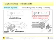
Insulation Strength Characteristics<br />
Topics to be covered in the following:<br />
• Insulators under polluted conditions<br />
• Probability of flashover (Normal and Weibull distributions)<br />
• Behavior of parallel insulation<br />
• Coordination procedure: deterministic and statistical approach<br />
• Correction with altitude of installation<br />
• Clearances in air; "gap factors"<br />
<strong>Fachgebiet</strong><br />
<strong>Hochspannungstechnik</strong><br />
Overvoltage Protection and Insulation Coordination / Chapter 7 - 1 -
Probability of Disruptive Discharge of Insulation<br />
The breakdown process is statistical in nature to be taken into account, especially for<br />
impulse voltage stress!<br />
Non-self-restoring insulation<br />
• No method at present available for the determination of the probability of disruptive discharge<br />
• Therefore, it is assumed that the withstand probability changes from 0% to 100% at the value<br />
defining the withstand voltage.<br />
• Withstand voltage usually verified by application of a limited number of test voltages at standard<br />
withstand level with no disruptive breakdown allowed "Procedure A" of IEC 60006-1:<br />
[IEC 60060-1]<br />
<strong>Fachgebiet</strong><br />
<strong>Hochspannungstechnik</strong><br />
Overvoltage Protection and Insulation Coordination / Chapter 7 - 2 -
Probability of Disruptive Discharge of Insulation<br />
The breakdown process is statistical in nature to be taken into account, especially for<br />
impulse voltage stress!<br />
Self-restoring insulation<br />
• Withstand capability can be evaluated by tests and be described in statistical terms.<br />
• Therefore, self-restoring insulation is typically described by the statistical withstand voltage<br />
corresponding to a withstand probability of 90%.<br />
• Withstand voltage verified by application of a limited number of test voltages at standard insulation<br />
level, allowing a certain number of discharges<br />
"Procedure B" of IEC 60060-1 "15/2-test" usually applied procedure in the "IEC world"<br />
"Procedure C" of IEC 60060-1 "3+9-test"<br />
See next three slides ….<br />
<strong>Fachgebiet</strong><br />
<strong>Hochspannungstechnik</strong><br />
Overvoltage Protection and Insulation Coordination / Chapter 7 - 3 -
Probability of Disruptive Discharge of Insulation<br />
[IEC 60060-1]<br />
<strong>Fachgebiet</strong><br />
<strong>Hochspannungstechnik</strong><br />
Overvoltage Protection and Insulation Coordination / Chapter 7 - 4 -
Probability of Disruptive Discharge of Insulation<br />
Comparison of Procedures B and C<br />
Only here both procedures are equivalent!<br />
[IEC 60071-2]<br />
Example:<br />
• equipment at the borderline, rated and tested at its U 10<br />
, has a 82% probability of passing the test in Procedure B<br />
• a better equipment, rated and tested at its U 5,5<br />
, has a 95% probability of passing the test in Procedure B<br />
• a worse equipment, rated and tested at its U 36<br />
, has only a 5% probability of passing the test in Procedure B;<br />
with Procedure C, its probability of passing would be higher, the 5% probability of passing would be given for<br />
equipment rated and tested at its U 63<br />
(see also next slide)<br />
<strong>Fachgebiet</strong><br />
<strong>Hochspannungstechnik</strong><br />
Overvoltage Protection and Insulation Coordination / Chapter 7 - 5 -
Probability of Disruptive Discharge of Insulation<br />
Comparison of Procedures B and C<br />
Probability of passing the test: approx. 82 %<br />
at probability of breakdown of 10 %<br />
Probability of breakdown P(U)<br />
Probability of passing the test "15/2"<br />
Probability of passing the test "3+9"<br />
1,0<br />
0,9<br />
0,8<br />
0,7<br />
0,6<br />
0,5<br />
0,4<br />
0,3<br />
0,2<br />
0,1<br />
Pb(U) P(U)<br />
15/2<br />
3+9<br />
0,0<br />
-3 -2,5 -2 -1,5 -1 -0,5 0 0,5 1 1,5 2 2,5<br />
(U-U50)/Z 50 Test voltage referred to conventional deviation<br />
<strong>Fachgebiet</strong><br />
<strong>Hochspannungstechnik</strong><br />
Overvoltage Protection and Insulation Coordination / Chapter 7 - 6 -
Probability of Disruptive Discharge of Insulation<br />
Comparison of Procedures B and C (IEC depiction)<br />
50 Equipment that has a<br />
5% probability of<br />
passing the 15/2-test,<br />
would have an approx.<br />
40% probability of<br />
passing the 3+9-test<br />
[IEC 60071-2]<br />
<strong>Fachgebiet</strong><br />
<strong>Hochspannungstechnik</strong><br />
Overvoltage Protection and Insulation Coordination / Chapter 7 - 7 -
Probability of Disruptive Discharge of Insulation<br />
Completely different approaches:<br />
• Verification of withstand voltages (see slides before)<br />
• Evaluation of withstand voltages<br />
Determination of the probability function P = P(U), defined by the three following<br />
parameters in case of a Normal or Gaussian distribution:<br />
U 50<br />
… voltage under which the insulation has a 50% probability to flashover or to withstand<br />
Z … conventional deviation; Z = U 50<br />
– U 16<br />
U 0<br />
… truncation voltage (cannot be directly determined)<br />
IEC 60071-2:<br />
"For insulation co-ordination purposes, the up-and-down withstand method with<br />
seven impulses per group and at least eight groups is the preferred method of<br />
determining U 50 ".<br />
<strong>Fachgebiet</strong><br />
<strong>Hochspannungstechnik</strong><br />
Overvoltage Protection and Insulation Coordination / Chapter 7 - 8 -
Probability of Disruptive Discharge of Insulation<br />
Up-and-down method (see HVT I, Ch. 5)<br />
Special case for determining U 50<br />
û 5<br />
∆U ≈ 3% of û 1<br />
û 4<br />
û<br />
û 3<br />
û 2<br />
û 1<br />
Count starts here<br />
breakdown<br />
no breakdown<br />
n<br />
General procedure see next slides…<br />
<strong>Fachgebiet</strong><br />
<strong>Hochspannungstechnik</strong><br />
Overvoltage Protection and Insulation Coordination / Chapter 7 - 9 -
Probability of Disruptive Discharge of Insulation<br />
[IEC 60060-1]<br />
See slide before!<br />
Examples see next slides….<br />
<strong>Fachgebiet</strong><br />
<strong>Hochspannungstechnik</strong><br />
Overvoltage Protection and Insulation Coordination / Chapter 7 - 10 -
Probability of Disruptive Discharge of Insulation<br />
Up-and-down method – Withstand procedure with m = 7 and n = 8<br />
û 5<br />
∆U ≈ 3% of û 1<br />
û 4<br />
û<br />
û 3<br />
û 2<br />
û 1<br />
Count starts here<br />
group of 7 impulses with at least one disruptive discharge<br />
group of 7 impulses with no disruptive discharge<br />
n<br />
<strong>Fachgebiet</strong><br />
<strong>Hochspannungstechnik</strong><br />
Overvoltage Protection and Insulation Coordination / Chapter 7 - 11 -
Probability of Disruptive Discharge of Insulation<br />
Up-and-down method – Discharge procedure with m = 7 and n = 8<br />
û 5<br />
∆U ≈ 3% of û 1<br />
û 4<br />
û<br />
û 3<br />
û 2<br />
û 1<br />
Count starts here<br />
group of 7 impulses with no withstand<br />
group of 7 impulses with at least one withstand<br />
n<br />
<strong>Fachgebiet</strong><br />
<strong>Hochspannungstechnik</strong><br />
Overvoltage Protection and Insulation Coordination / Chapter 7 - 12 -
Probability of Disruptive Discharge of Insulation<br />
Replacing the Normal (Gaussian) by a Weibull distribution<br />
Disruptive discharge probability described by a Gaussian cumulative frequency distribution:<br />
1 2<br />
1<br />
y<br />
2<br />
P( U ) = −<br />
e dy<br />
2π<br />
∫<br />
where<br />
x<br />
−∞<br />
x = ( U −U50) / Z<br />
U 50<br />
… 50% discharge voltage (P(U 50<br />
) = 0.5)<br />
Z … conventional deviation<br />
In order to reflect the real physical behavior, this function has to be truncated at<br />
U 0<br />
= U 50<br />
– 3Z or<br />
U 0<br />
= U 50<br />
– 4Z<br />
(No discharge can occur at voltages below U 0<br />
!)<br />
<strong>Fachgebiet</strong><br />
<strong>Hochspannungstechnik</strong><br />
Overvoltage Protection and Insulation Coordination / Chapter 7 - 13 -
Probability of Disruptive Discharge of Insulation<br />
Replacing the Normal (Gaussian) by a Weibull distribution<br />
Arguments for replacing the Gaussian by the Weibull distribution:<br />
• the truncation value U 0<br />
is mathematically included in the Weibull expression;<br />
• the function is easily evaluated by pocket calculators;<br />
• the inverse function U = U(P) can be expressed mathematically and is easily evaluated<br />
by pocket calculators;<br />
• the modified Weibull expression is defined by the same parameters characterizing the<br />
truncated Gaussian expression: U 50<br />
, Z and U 0<br />
;<br />
• the disruptive discharge probability function of several identical insulations in parallel has<br />
the same expression as that of one insulation and its characteristics can be easily<br />
determined from those of the single insulation.<br />
<strong>Fachgebiet</strong><br />
<strong>Hochspannungstechnik</strong><br />
Overvoltage Protection and Insulation Coordination / Chapter 7 - 14 -
Probability of Disruptive Discharge of Insulation<br />
Replacing the Normal (Gaussian) by a Weibull distribution<br />
General expression for Weibull distribution:<br />
⎛U<br />
−δ<br />
⎞<br />
−⎜ ⎟<br />
⎝ β ⎠<br />
P( U ) = 1− e where<br />
γ<br />
δ … truncation value<br />
β … scale parameter<br />
γ … shape parameter<br />
Modification for description of discharge probability of an insulation with a truncated<br />
discharge probability:<br />
δ =<br />
U50<br />
−<br />
NZ<br />
β =<br />
γ<br />
NZ(ln 2)<br />
1<br />
−<br />
γ<br />
1<br />
⎛<br />
⎞<br />
⎛<br />
⎞<br />
⎜ γ<br />
U − U50<br />
+ NZ ⎟ ⎜ ( U − U50<br />
+ NZ )(ln 2) ⎟<br />
−⎜<br />
1<br />
⎟<br />
−⎜<br />
⎟<br />
−<br />
NZ<br />
⎛U − U50<br />
+ NZ ⎞<br />
⎜ γ<br />
−<br />
NZ (ln 2)<br />
⎟ ⎜ ⎟ ⎜ ⎟<br />
⎝ ⋅ ⎠ ⎝ ⎠ ⎝ NZ ⎠<br />
P( U ) = 1− e = 1− e = 1−<br />
e<br />
γ<br />
(N may be 3 or 4)<br />
γ<br />
ln 2<br />
γ<br />
γ<br />
50 ⎛ U −U<br />
U −U<br />
50 ⎞<br />
50<br />
⎛ U −U<br />
⎞ ⎛ ⎞<br />
− ⎜1+ ⎟ ln 2 1+<br />
⎜1+<br />
⎟<br />
⎝ NZ ⎠<br />
⎜ ⎟<br />
⎝ NZ ⎠<br />
⎝ NZ ⎠<br />
− ln 2<br />
( e )<br />
= 1− e = 1− = 1−<br />
0.5<br />
γ<br />
<strong>Fachgebiet</strong><br />
<strong>Hochspannungstechnik</strong><br />
Overvoltage Protection and Insulation Coordination / Chapter 7 - 15 -
Probability of Disruptive Discharge of Insulation<br />
Replacing the Normal (Gaussian) by a Weibull distribution<br />
P( U ) = 1−<br />
0.5<br />
Condition: 50<br />
⎛ U −U<br />
⎜1+<br />
⎝ NZ<br />
50<br />
γ<br />
⎞<br />
⎟<br />
⎠<br />
P( U − Z) = 0.16<br />
Solving the equation to γ:<br />
⎛ U<br />
⎜1+<br />
⎝<br />
−Z −U<br />
50 50<br />
ZN ⎠<br />
1− 0.5 = 0.16<br />
⎛ 1 ⎞<br />
⎜1−<br />
⎟<br />
⎝ N ⎠<br />
γ<br />
⎞<br />
⎟<br />
1− 0.5 = 0.16<br />
γ<br />
γ<br />
⎛ 1 ⎞<br />
⎜1−<br />
⎟<br />
N<br />
⎝ ⎠<br />
0.5 = 1−<br />
0.16<br />
γ<br />
⎛ ⎛ 1 ⎞<br />
⎜1−<br />
⎟<br />
⎞<br />
⎝ N ⎠<br />
ln 0.5 = ln 1−<br />
0.16<br />
⎜ ⎟<br />
⎝ ⎠<br />
( )<br />
<strong>Fachgebiet</strong><br />
<strong>Hochspannungstechnik</strong><br />
Overvoltage Protection and Insulation Coordination / Chapter 7 - 16 -
Probability of Disruptive Discharge of Insulation<br />
Replacing the Normal (Gaussian) by a Weibull distribution<br />
γ<br />
⎛ 1 ⎞<br />
⎜1− ⎟ ln 0.5 = ln 1−<br />
0.16<br />
⎝ N ⎠<br />
( ) ( )<br />
γ<br />
⎛ 1 ⎞<br />
⎜1− ⎟ =<br />
⎝ N ⎠<br />
( − )<br />
ln ( 0.5)<br />
ln 1 0.16<br />
( − )<br />
ln ( 0.5)<br />
γ<br />
⎛ 1 ⎞ ⎛ ln 1 0.16 ⎞<br />
ln ⎜1− ⎟ = ln ⎜ ⎟<br />
⎝ N ⎠ ⎝ ⎠<br />
( − )<br />
ln ( 0.5)<br />
⎛ 1 ⎞ ⎛ ln 1 0.16 ⎞<br />
γ ln ⎜1− ⎟ = ln ⎜ ⎟<br />
⎝ N ⎠ ⎝ ⎠<br />
γ =<br />
( − )<br />
ln ( 0.5)<br />
⎛ ln 1 0.16<br />
ln ⎜<br />
⎝<br />
⎛ 1 ⎞<br />
ln ⎜1−<br />
⎟<br />
⎝ N ⎠<br />
⎞<br />
⎟<br />
⎠<br />
<strong>Fachgebiet</strong><br />
<strong>Hochspannungstechnik</strong><br />
Overvoltage Protection and Insulation Coordination / Chapter 7 - 17 -
Probability of Disruptive Discharge of Insulation<br />
Replacing the Normal (Gaussian) by a Weibull distribution<br />
γ =<br />
( − )<br />
ln ( 0.5)<br />
⎛ ln 1 0.16<br />
ln ⎜<br />
⎝<br />
⎛ 1 ⎞<br />
ln ⎜1−<br />
⎟<br />
⎝ N ⎠<br />
⎞<br />
⎟<br />
⎠<br />
Assuming that U 0<br />
= U 50<br />
– 4Z N = 4<br />
( − )<br />
ln ( 0.5)<br />
( − )<br />
⎛ ln 1 0.16 ⎞<br />
ln ⎜<br />
⎟<br />
γ =<br />
⎝<br />
⎠<br />
= 4,80 ≈ 5<br />
ln 1 0.25<br />
(reasonably accurate)<br />
<strong>Fachgebiet</strong><br />
<strong>Hochspannungstechnik</strong><br />
Overvoltage Protection and Insulation Coordination / Chapter 7 - 18 -
Probability of Disruptive Discharge of Insulation<br />
Replacing the Normal (Gaussian) by a Weibull distribution<br />
γ<br />
50 U −U<br />
50<br />
⎛ U −U<br />
⎞ ⎛ ⎞<br />
⎜1+ ⎟ ⎜1+<br />
⎟<br />
⎝ NZ ⎠ ⎝ 4Z<br />
⎠<br />
P( U ) = 1− 0.5 = 1−<br />
0.5<br />
5<br />
With x = (U – U 50<br />
)/Z:<br />
⎛ ⎞<br />
⎜1+<br />
⎟<br />
⎝ 4 ⎠<br />
P ( U ) = 1 − 0.5<br />
x<br />
5<br />
Modified Weibull flashover probability<br />
Typical values for Z (if more accurate data are missing):<br />
For lightning impulses: Z = 0.03 U 50 [Z] = kV<br />
For switching impulses: Z = 0.06 U 50<br />
And for U 10<br />
, resulting from the distribution function:<br />
U 10 = U 50 – 1.3 Z see also chapter 3<br />
<strong>Fachgebiet</strong><br />
<strong>Hochspannungstechnik</strong><br />
Overvoltage Protection and Insulation Coordination / Chapter 7 - 19 -
Probability of Disruptive Discharge of Insulation<br />
Replacing the Normal (Gaussian) by a Weibull distribution<br />
[IEC 60071-2]<br />
<strong>Fachgebiet</strong><br />
<strong>Hochspannungstechnik</strong><br />
Overvoltage Protection and Insulation Coordination / Chapter 7 - 20 -
Probability of Disruptive Discharge of Insulation<br />
Many insulations in parallel<br />
Question: if the probability of flashover of one insulator at U is P(U), what is the probability<br />
P'(U) of M of these insulators connected in parallel to flashover?<br />
P(U) P 1<br />
(U) P 2<br />
(U) P 3<br />
(U) P 4<br />
(U) P 5<br />
(U) ........ P M<br />
(U)<br />
P‘(U) = ?<br />
<strong>Fachgebiet</strong><br />
<strong>Hochspannungstechnik</strong><br />
Overvoltage Protection and Insulation Coordination / Chapter 7 - 21 -
Probability of Disruptive Discharge of Insulation<br />
Many insulations in parallel<br />
Applying the rules of statistics:<br />
Probability of flashover of one single insulator: P(U)<br />
If many insulators of the same individual flashover probability are connected in parallel<br />
and one is looking for the probability of a flashover of one of them, this cannot be<br />
calculated by an addition of the individual probabilities. (Note: if this was the case, 100<br />
parallel insulators of 10% flashover probability (P(U) = 0.1) would have a probability of<br />
P'(U) = 10 to flashover, which is mathematical nonsense.)<br />
Solution: consider the probability of withstand: W(U) = 1 – P(U)<br />
The probability that a number of M insulators withstands at the same time can be<br />
calculated by multiplication according to the rules of statistics:<br />
W total<br />
(U) = W 1<br />
(U) · W 2<br />
(U) · W 3<br />
(U) · ….. · W M<br />
(U) = W(U) M = [1-P(U)] M<br />
The probability P'(U) that one out of M insulators flashes over is equal to the probability<br />
that not all insulators withstand at the same time, thus:<br />
[ P U ]<br />
P′ ( U ) = 1− 1 − ( ) M<br />
<strong>Fachgebiet</strong><br />
<strong>Hochspannungstechnik</strong><br />
Overvoltage Protection and Insulation Coordination / Chapter 7 - 22 -
Probability of Disruptive Discharge of Insulation<br />
Many insulations in parallel<br />
[ P U ]<br />
P′ ( U ) = 1− 1 − ( ) M<br />
⎛ ⎞<br />
⎜1+<br />
⎟<br />
⎝ 4 ⎠<br />
P ( U ) = 1 − 0.5<br />
x<br />
5<br />
5<br />
⎛ x ⎞<br />
M ⎜1+<br />
⎟<br />
P ( U ) 1 0.5<br />
⎝ 4 ⎠<br />
′ = − Flashover probability of M parallel insulations<br />
Introducing the normalized variable x M<br />
= (U – U 50M<br />
)/Z M<br />
:<br />
P′ ( U ) = 1−<br />
0.5<br />
⎛<br />
⎜1+<br />
⎝<br />
x M<br />
4<br />
⎞<br />
⎟<br />
⎠<br />
5<br />
Comparison of both equations yields:<br />
x<br />
x<br />
+ = M ⎛ ⎜ +<br />
⎞ ⎟<br />
4 ⎝ 4 ⎠<br />
M 5<br />
1 1<br />
<strong>Fachgebiet</strong><br />
<strong>Hochspannungstechnik</strong><br />
Overvoltage Protection and Insulation Coordination / Chapter 7 - 23 -
Probability of Disruptive Discharge of Insulation<br />
Many insulations in parallel<br />
x<br />
x<br />
+ = M ⎛ ⎜ +<br />
⎞ ⎟<br />
4 ⎝ 4 ⎠<br />
M 5<br />
1 1<br />
Replacing x and x M<br />
by their extended definitions:<br />
x = (U – U 50<br />
)/Z<br />
x M<br />
= (U – U 50M<br />
)/Z M<br />
and because:<br />
U 50<br />
– 4Z = U 50M<br />
– 4Z M<br />
= U 0<br />
Z<br />
M<br />
Z<br />
= U<br />
5<br />
50M<br />
= U50 − 4Z<br />
⎜1−<br />
5<br />
M<br />
⎛<br />
⎝<br />
1<br />
M<br />
⎞<br />
⎟<br />
⎠<br />
<strong>Fachgebiet</strong><br />
<strong>Hochspannungstechnik</strong><br />
Overvoltage Protection and Insulation Coordination / Chapter 7 - 24 -
Probability of Disruptive Discharge of Insulation<br />
Many insulations in parallel<br />
Z<br />
M<br />
Z<br />
= U<br />
5<br />
50M<br />
= U50 − 4Z<br />
⎜1−<br />
5<br />
M<br />
⎛<br />
⎝<br />
1<br />
M<br />
⎞<br />
⎟<br />
⎠<br />
Example 1:<br />
For M = 200:<br />
U 50(200)<br />
= U 50<br />
– 2.6 Z<br />
U 10(200)<br />
= U 50(200)<br />
– 1.3 Z 200<br />
= U 50<br />
– 3.1 Z<br />
Example 2:<br />
M = 100, U 50<br />
= 1600 kV, Z = 100 kV<br />
Z M<br />
= 39.8 kV, U 50M<br />
= 1359.2 kV<br />
<strong>Fachgebiet</strong><br />
<strong>Hochspannungstechnik</strong><br />
Overvoltage Protection and Insulation Coordination / Chapter 7 - 25 -
Probability of Disruptive Discharge of Insulation<br />
Many insulations in parallel<br />
Z<br />
M<br />
Z<br />
= U<br />
5<br />
50M<br />
= U50 − 4Z<br />
⎜1−<br />
5<br />
M<br />
⎛<br />
⎝<br />
1<br />
M<br />
⎞<br />
⎟<br />
⎠<br />
Example 2, continued:<br />
[IEC 60071-2]<br />
<strong>Fachgebiet</strong><br />
<strong>Hochspannungstechnik</strong><br />
Overvoltage Protection and Insulation Coordination / Chapter 7 - 26 -
Probability of Disruptive Discharge of Insulation<br />
Many insulations in parallel<br />
Note: These values can<br />
directly be obtained from this<br />
equation:<br />
[ P U ]<br />
P′ ( U ) = 1− 1 − ( ) M<br />
see Example 1:<br />
U 50(200)<br />
= U 50<br />
– 2.6 Z<br />
[IEC 60071-2]<br />
<strong>Fachgebiet</strong><br />
<strong>Hochspannungstechnik</strong><br />
Overvoltage Protection and Insulation Coordination / Chapter 7 - 27 -
Probability of Disruptive Discharge of Insulation<br />
Many insulations in parallel<br />
… also relevant for apparatus design<br />
Grading capacitors<br />
Breaking chambers<br />
Closing resistors<br />
three parallel external insulations<br />
one external insulation<br />
<strong>Fachgebiet</strong><br />
<strong>Hochspannungstechnik</strong><br />
Overvoltage Protection and Insulation Coordination / Chapter 7 - 28 -
Insulation Strength in Air<br />
Factors influencing the dielectric strength of the insulation:<br />
• magnitude, shape, duration and polarity of the applied voltage<br />
• electric field distribution in the insulation<br />
• homogeneous or non-homogeneous electric field<br />
• electrodes adjacent to the considered gap and their potential<br />
• type of insulation<br />
• gaseous<br />
• liquid<br />
• solid<br />
• combination of two or all of them<br />
• impurity content and the presence of local inhomogeneities<br />
• physical state of the insulation<br />
• temperature<br />
• pressure<br />
• other ambient conditions<br />
• mechanical stress<br />
• history of the insulation (aging, damage)<br />
• chemical effects<br />
• conductor surface effects<br />
Covered by equations U 50RP = f(d)<br />
where<br />
U 50RP … 50% probability<br />
breakdown voltage of<br />
a rod-plane-configuration<br />
d … gap spacing<br />
Covered by equations U 50 = f(U 50RP , K)<br />
where<br />
K … gap factor<br />
K is a factor indicating how much higher the<br />
electrical strength of a particular electrode<br />
configuration is in comparison with the rod-planeconfiguration<br />
(which gives least dielectric strength);<br />
factors K were experimentally found for standard<br />
switching impulse voltage stress<br />
<strong>Fachgebiet</strong><br />
<strong>Hochspannungstechnik</strong><br />
Overvoltage Protection and Insulation Coordination / Chapter 7 - 29 -
Insulation Strength in Air<br />
Gap factors (Table G.1 of IEC 60071-2)<br />
<strong>Fachgebiet</strong><br />
<strong>Hochspannungstechnik</strong><br />
Overvoltage Protection and Insulation Coordination / Chapter 7 - 30 -
Insulation Strength in Air<br />
Gap factors (Table G.1 of IEC 60071-2)<br />
<strong>Fachgebiet</strong><br />
<strong>Hochspannungstechnik</strong><br />
Overvoltage Protection and Insulation Coordination / Chapter 7 - 31 -
Insulation Strength in Air<br />
Gap factors (Table G.1 of IEC 60071-2)<br />
<strong>Fachgebiet</strong><br />
<strong>Hochspannungstechnik</strong><br />
Overvoltage Protection and Insulation Coordination / Chapter 7 - 32 -
Insulation Strength in Air<br />
Gap factors (Table G.1 of IEC 60071-2)<br />
<strong>Fachgebiet</strong><br />
<strong>Hochspannungstechnik</strong><br />
Overvoltage Protection and Insulation Coordination / Chapter 7 - 33 -
Insulation Strength in Air<br />
Gap factors [Electra No. 29 (1973),<br />
pp. 29-44)]<br />
Electrode configuration<br />
Rod-plane<br />
K<br />
1.0<br />
Increasing dielectric strength<br />
Rod-structure (under)<br />
Conductor-plane<br />
Conductor-window<br />
Conductor-structure (under)<br />
Rod-rod (h = 6 m, under)<br />
Conductor-structure<br />
(over and laterally)<br />
Conductor-rope<br />
(under and laterally)<br />
Conductor-crossarm (end)<br />
Conductor-rod (h = 3 m, under)<br />
Conductor-rod (h = 6 m, under)<br />
1.05<br />
1.15<br />
1.20<br />
1.30<br />
1.30<br />
1.35<br />
1.40<br />
1.55<br />
1.65<br />
1.90<br />
<strong>Fachgebiet</strong><br />
<strong>Hochspannungstechnik</strong><br />
Overvoltage Protection and Insulation Coordination / Chapter 7 - 34 -
Insulation Strength in Air<br />
Insulation response to power-frequency voltages (IEC60071-2, Annex G)<br />
U<br />
1.2<br />
50RP<br />
= 750⋅ 2 ⋅ ln(1 + 0.55 ⋅ d )<br />
U<br />
with<br />
U 50RP<br />
… crest value in kV<br />
d in m; d ≤ 3 m<br />
= U<br />
50 50RP<br />
50 50RP<br />
exact for d < 1 m; conservative for 1 m ≤ d ≤ 2 m<br />
(<br />
2<br />
1.35 0.35 )<br />
U = U K − K for d > 2 m<br />
≈ 300 kV/m (r.m.s. value)<br />
U<br />
≈ 0.9 ⋅U<br />
0 50<br />
(assuming U 0<br />
= U 50<br />
- 4Z and Z = 0.03 U 50<br />
)<br />
• influence of rain in an air gap negligible; but for insulators to be considered!<br />
• pollution for insulators to be considered!<br />
• altitude correction required!<br />
<strong>Fachgebiet</strong><br />
<strong>Hochspannungstechnik</strong><br />
Overvoltage Protection and Insulation Coordination / Chapter 7 - 35 -
Insulation Strength in Air<br />
Insulation response to slow-front overvoltages (IEC60071-2, Annex G)<br />
U50RP = 1080⋅ln(0.46 ⋅ d + 1)<br />
with<br />
U 50RP<br />
… in kV; for positive polarity at most critical front-time (see Ch. 3)<br />
d in m; d ≤ 25 m<br />
U<br />
= ⋅d<br />
50RP<br />
500<br />
0.6<br />
with<br />
U 50RP<br />
… in kV; for positive polarity standard switching impulse voltage (see Ch. 3)<br />
d in m; d ≤ 25 m<br />
U<br />
= KU Note: for K ≥ 1.45 U 50neg. may become lower than U 50pos.<br />
50 50RP<br />
<strong>Fachgebiet</strong><br />
<strong>Hochspannungstechnik</strong><br />
Overvoltage Protection and Insulation Coordination / Chapter 7 - 36 -
Insulation Strength in Air<br />
Insulation response to slow-front overvoltages (IEC60071-2, Annex G)<br />
U<br />
≈ 0.75⋅ U (assuming U 0<br />
= U 50<br />
- 4Z and Z = 0.06 U 50<br />
)<br />
0 50<br />
• influence of rain in an air gap negligible; but for insulators to be considered!<br />
• altitude correction required!<br />
<strong>Fachgebiet</strong><br />
<strong>Hochspannungstechnik</strong><br />
Overvoltage Protection and Insulation Coordination / Chapter 7 - 37 -
Insulation Strength in Air<br />
Insulation response to slow-front overvoltages (IEC60071-2, Annex G)<br />
For phase-to-phase insulation similar gap factors as for phase-to-earth insulation<br />
can be applied.<br />
But: the influence of negative and positive components has to be taken into<br />
account by a factor α:<br />
peak negative component<br />
α<br />
= sum of peak negative and positive components<br />
[IEC 60071-2]<br />
<strong>Fachgebiet</strong><br />
<strong>Hochspannungstechnik</strong><br />
Overvoltage Protection and Insulation Coordination / Chapter 7 - 38 -
Insulation Strength in Air<br />
Insulation response to fast-front overvoltages (IEC60071-2, Annex G)<br />
U<br />
= ⋅d<br />
50RP<br />
530<br />
i.e. linear increase with gap spacing<br />
with<br />
U 50RP<br />
… in kV; for positive polarity<br />
d in m; d ≤ 10 m<br />
Note: for negative LI voltages, dielectric<br />
strength is higher and increases nonlinearly<br />
with gap spacing!<br />
The gap factors K (found for SI voltages!) cannot be directly applied.<br />
<strong>From</strong> experimental investigations:<br />
U = K ⋅U<br />
+<br />
50 ff 50RP<br />
K<br />
+ ff<br />
= 0.74 + 0.26K<br />
with<br />
K + ff<br />
… fast-front overvoltage gap factor<br />
for positive polarity<br />
K …... gap factor for SI voltage<br />
according to tables<br />
<strong>Fachgebiet</strong><br />
<strong>Hochspannungstechnik</strong><br />
Overvoltage Protection and Insulation Coordination / Chapter 7 - 39 -
Insulation Strength in Air<br />
Insulation response to fast-front overvoltages (IEC60071-2, Annex G)<br />
Estimation of negative line insulator flashover voltage (in order to determine lightning<br />
overvoltages impinging on a substation:<br />
U<br />
= ⋅d<br />
50 neg, line insulator<br />
700<br />
• influence of insulators to be considered particularly for range II!<br />
• less influence from long insulators without metallic parts (long rod, composite, station<br />
post) than for cap-and-pin insulators<br />
• altitude correction required!<br />
• virtually no influence of rain neither for air gaps nor for insulators<br />
Conventional deviation:<br />
Z ≈ 0.03·U 50 for air gaps and positive polarity<br />
Z ≈ 0.05·U 50 for air gaps and negative polarity<br />
Z ≈ (0.05 … 0.09)·U 50 across insulators<br />
<strong>Fachgebiet</strong><br />
<strong>Hochspannungstechnik</strong><br />
Overvoltage Protection and Insulation Coordination / Chapter 7 - 40 -
Insulation Strength in Air<br />
Independent from the theoretical and empirical background given so far, IEC 60071-2<br />
offers tables on minimum clearances in air (Annex A). Not all values of these tables<br />
can be derived from above equations, as they additionally take into account<br />
• withstand values instead of U 50<br />
-values<br />
• feasibility<br />
• economy<br />
• experience<br />
• average influence of environmental conditions (pollution, rain, insects, …)<br />
<strong>Fachgebiet</strong><br />
<strong>Hochspannungstechnik</strong><br />
Overvoltage Protection and Insulation Coordination / Chapter 7 - 41 -
Insulation Strength in Air<br />
[IEC 60071-2]<br />
<strong>Fachgebiet</strong><br />
<strong>Hochspannungstechnik</strong><br />
Overvoltage Protection and Insulation Coordination / Chapter 7 - 42 -
Procedure for Insulation Coordination in Four Steps<br />
Next slide<br />
Flow chart of IEC 60071-1<br />
(Figure 1)<br />
we are here!<br />
Sorry, no time this year<br />
[IEC 60071-1]<br />
<strong>Fachgebiet</strong><br />
<strong>Hochspannungstechnik</strong><br />
Overvoltage Protection and Insulation Coordination / Chapter 7 - 43 -
Insulation Strength in Air<br />
Performance criterion IEC 60071-2, Cl. 3.2<br />
According to definition 3.22 of IEC 71-1, the performance criterion to be required from the<br />
insulation in service is the acceptable failure rate (R a<br />
).<br />
The performance of the insulation in a system is judged on the basis of the number of<br />
insulation failures during service. Faults in different parts of the network can have different<br />
consequences. For example, in a meshed system a permanent line fault or an unsuccessful<br />
reclosure due to slow-front surges is not as severe as a busbar fault or corresponding faults<br />
in a radial network. Therefore, acceptable failure rates in a network can vary from point to<br />
point depending on the consequences of a failure at each of these points.<br />
Examples for acceptable failure rates can be drawn from fault statistics covering the existing<br />
systems and from design projects where statistics have been taken into account. For<br />
apparatus, acceptable failure rates R a<br />
due to overvoltages are in the range of 0.001/year<br />
up to 0.004/year depending on the repair times. For overhead lines acceptable failure rates<br />
due to lightning vary in the range of 0.1/100 km/year up to 20/100 km/year (the greatest<br />
number being for distribution lines). Corresponding figures for acceptable failure rates due to<br />
switching overvoltages lie in the range 0.01 to 0.001 per operation. Values for<br />
acceptable failure rates should be in these orders of magnitude.<br />
<strong>Fachgebiet</strong><br />
<strong>Hochspannungstechnik</strong><br />
Overvoltage Protection and Insulation Coordination / Chapter 7 - 44 -
Insulation Strength in Air<br />
Altitude correction<br />
In general, withstand or breakdown voltages must be corrected for air density (pressure,<br />
temperature) and absolute humidity.<br />
Temperature and absolute humidity tend to cancel out each other. Thus correction is<br />
mainly required for pressure, which has its strongest influence in the altitude of<br />
installation.<br />
Therefore, in the procedure of insulation coordination, an altitude correction must be<br />
performed in the step from the coordination withstand voltage U cw<br />
to the required<br />
withstand voltage U rw<br />
.<br />
−<br />
H<br />
Air density vs. altitude: 8150<br />
δ = e (regression of experimental data)<br />
where H … altitude above sea level in m<br />
Voltage correction depends on voltage shape (the kind of pre-discharges), thus a voltagedependant<br />
factor m is introduced:<br />
k = e<br />
H<br />
−m<br />
8150<br />
<strong>Fachgebiet</strong><br />
<strong>Hochspannungstechnik</strong><br />
Overvoltage Protection and Insulation Coordination / Chapter 7 - 45 -
Insulation Strength in Air<br />
Altitude correction<br />
m = 1 for LI voltage<br />
m = acc. to Figure 9 for SI voltage<br />
m = 1 for short-time alternating voltage<br />
m = 0.5 for long-time alternating<br />
voltage and tests under pollution<br />
Final altitude correction factor:<br />
K<br />
a<br />
1<br />
= =<br />
k<br />
e<br />
H<br />
m<br />
8150<br />
[IEC 60071-2]<br />
approx. 1.3% per 100 m (for m = 1)<br />
<strong>Fachgebiet</strong><br />
<strong>Hochspannungstechnik</strong><br />
Overvoltage Protection and Insulation Coordination / Chapter 7 - 46 -
Procedure for Insulation Coordination in Four Steps<br />
Flow chart of IEC 60071-1<br />
(Figure 1)<br />
we are here!<br />
[IEC 60071-1]<br />
<strong>Fachgebiet</strong><br />
<strong>Hochspannungstechnik</strong><br />
Overvoltage Protection and Insulation Coordination / Chapter 7 - 47 -
Procedure for Insulation Coordination in Four Steps<br />
<strong>From</strong> U cw<br />
U rw<br />
Urw = Ka ⋅ Ks ⋅Ucw<br />
where K a<br />
… altitude correction factor<br />
K s<br />
… safety factor, taking into account:<br />
• differences in equipment assembly<br />
• dispersion in product quality<br />
• quality of installation<br />
• aging effects<br />
• other unknown influences<br />
Internal insulation:<br />
• no altitude correction (K a = 1)<br />
• K s = 1.15<br />
External insulation:<br />
• K a = f(m,H) = exp(m·H/8150)<br />
• K s = 1.05<br />
<strong>Fachgebiet</strong><br />
<strong>Hochspannungstechnik</strong><br />
Overvoltage Protection and Insulation Coordination / Chapter 7 - 48 -
Procedure for Insulation Coordination in Four Steps<br />
Example (for m = 1)<br />
2000<br />
<strong>From</strong> U cw<br />
U rw<br />
1500<br />
1000<br />
U/kV<br />
External insulation: U rw<br />
= 1.05·exp(H/8150)·1000 kV<br />
Internal insulation: U rw<br />
= 1.15·1000 kV = 1150 kV<br />
Assumption: U cw<br />
= 1000 kV<br />
≈<br />
0 1000 2000 3000 H/m 4000<br />
<strong>Fachgebiet</strong><br />
<strong>Hochspannungstechnik</strong><br />
Overvoltage Protection and Insulation Coordination / Chapter 7 - 49 -
Procedure for Insulation Coordination in Four Steps<br />
Flow chart of IEC 60071-1<br />
(Figure 1)<br />
we arrived here!<br />
[IEC 60071-1]<br />
<strong>Fachgebiet</strong><br />
<strong>Hochspannungstechnik</strong><br />
Overvoltage Protection and Insulation Coordination / Chapter 7 - 50 -
Insulation Coordination<br />
For calculation examples, see IEC 60071-2, Annex H!<br />
<strong>Fachgebiet</strong><br />
<strong>Hochspannungstechnik</strong><br />
Overvoltage Protection and Insulation Coordination / Chapter 7 - 51 -
Insulation Coordination<br />
<strong>Fachgebiet</strong><br />
<strong>Hochspannungstechnik</strong><br />
Overvoltage Protection and Insulation Coordination / Chapter 7 - 52 -