Manual (PDF) - Rika
Manual (PDF) - Rika
Manual (PDF) - Rika

Create successful ePaper yourself
Turn your PDF publications into a flip-book with our unique Google optimized e-Paper software.
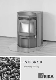
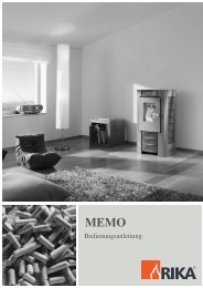
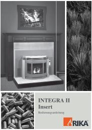
MEMO<br />
Instruction <strong>Manual</strong><br />
- 1 -
DIMENSIONS<br />
- 2 -
SPARE PART OVERVIEW<br />
- 3 -
- 4 -
- 5 -
- 6 -
CONTENTS<br />
DIMENSIONS.............................................................................. 2<br />
SPARE PART OVERVIEW......................................................3-6<br />
E N G L I S H<br />
Drawing explanation.................................................................... 8<br />
Technical data............................................................................. 9<br />
Packaging ................................................................................... 9<br />
Spare part overview .................................................................... 9<br />
1. IMPORTANT INFORMATION<br />
General warning and safety information.................................... 10<br />
2. WHAT ARE PELLETS?<br />
Wood pellet specifications......................................................... 11<br />
Pellet storage ............................................................................ 11<br />
3. TECHNOLOGY<br />
Easy operation and operational safety ...................................... 12<br />
Top efficiency – lowest emissions ............................................. 12<br />
4. AUTOMATIC SAFETY FUNCTIONS<br />
Power failure (heating operation) .............................................. 12<br />
Power failure (start phase) ........................................................ 12<br />
Overheating............................................................................... 12<br />
Low-temperature shutdown....................................................... 12<br />
Electrical excess current protection........................................... 12<br />
5. INSTALLATION OF THE STOVE<br />
General information................................................................... 13<br />
Connecting the stove................................................................. 13<br />
Floor protection ......................................................................... 13<br />
Electrical connection ................................................................. 13<br />
Combustion air .......................................................................... 14<br />
Infeed of external combustion air .............................................. 14<br />
6. DISASSEMBLY OF PANELS<br />
General ..................................................................................... 14<br />
Disassembly of the steel or ceramic panels .............................. 14<br />
7. OPERATION<br />
Basic information....................................................................... 15<br />
Control and function .................................................................. 15<br />
Internal control unit.................................................................... 15<br />
Simple heating operation – EASY MODE – the first steps ........ 15<br />
EASY OFF – inactive state........................................................ 16<br />
Start – ignition process.............................................................. 16<br />
EASY 40 – operation................................................................. 16<br />
EASY 40 – switch-off................................................................. 16<br />
Extended heating operation - HEAT MODE - comfort functions 17<br />
Menu structure and main menu level ........................................ 18<br />
Main menu TIME – time adjustment.......................................... 19<br />
Main menu SETUP – additional functions ............................ 20-21<br />
Main menu INFO – additional information............................ 22-23<br />
Comfort function – external room thermostat ............................ 24<br />
8. OPTIONS<br />
Room sensor – wireless room sensor ....................................... 24<br />
Telephone option - GSM ........................................................... 24<br />
9. ELECTRICAL IGNITION – EMERGENCY OPERATION<br />
Emergency operation – heating-up without electrical ignition.... 25<br />
Some values from practice........................................................ 25<br />
Adding fuel ................................................................................ 25<br />
- 7 -
E N G L I S H<br />
10. CLEANING AND MAINTENANCE<br />
Basic information....................................................................... 26<br />
Control handle front door........................................................... 26<br />
Cleaning fire trough................................................................... 26<br />
Cleaning front door glass .......................................................... 26<br />
Cleaning flues....................................................................... 26-27<br />
Cleaning flue main duct............................................................. 27<br />
Cleaning flue blower casing ...................................................... 28<br />
Cleaning pellet container........................................................... 28<br />
Checking door seal.................................................................... 28<br />
Checking stove connection ....................................................... 28<br />
11. MALFUNCTIONS – CAUSES – SOLUTIONS.......................... 29<br />
12. PUTTING INTO OPERATION<br />
Instructions for protocol for putting into operation...................... 30<br />
Protocol for putting into operation.............................................. 31<br />
13. MENU NAVIGATION – OVERALL VIEW ................................32-33<br />
14. GUARANTEE............................................................................ 34<br />
Commissioning report....................................................... 35-36<br />
DRAWING EXPLANATION<br />
All technical and layout changes as well as grammatical and printing faults excepted.<br />
Important information<br />
Practical advice<br />
- 8 -
TECHNICAL DATA<br />
(Fig. 2)<br />
TECHNICAL SPECIFICATION<br />
Dimensions (mm) and weights (kg)<br />
Height 978<br />
Width 495<br />
Depth of the corpus 544<br />
Weight with steel casing 95<br />
Weight with ceramic casing 110<br />
Flue tube outlet diameter 100<br />
Heating capacity range<br />
2,4-9 kW<br />
Room heating capacity (m3)<br />
depended on the house insulation<br />
50-240<br />
Fuel consumption<br />
Up to 2,2 kg/h<br />
Pellet container capacity<br />
21 kg<br />
Mains supply<br />
Average electric power<br />
consuption<br />
230V/50Hz<br />
∼ 20 W<br />
Fuse<br />
1,6 delay<br />
action<br />
Degree of efficiency 92,1 %<br />
CO2 content 11,1 %<br />
CO emission (at 13% O) 34 mg/Nm3<br />
Dust emissions<br />
22 mg/Nm3<br />
Exhaust gas mass flow<br />
6,45 g/s<br />
Exhaust gas temperature 144 C°<br />
Flue draught requirement<br />
0 PA<br />
The owner of small firing systems or the person<br />
authorised for the small firing system is to keep the<br />
technical documentation and is to submit it to the<br />
authorities or the chimney sweep on request.<br />
Please observe the national and European<br />
standards as well as local regulations<br />
concerning the installation and operation of<br />
firing installations!<br />
PACKAGING<br />
Your first impression is important to us!<br />
- The packaging of your new stove provides<br />
excellent protection against damage. In spite of this<br />
the stove and accessories can be damaged during<br />
transport.<br />
Therefore please check your stove on receipt for<br />
damage and completeness! Report any deficiencies to<br />
your dealer immediately! Pay particular attention<br />
during unpacking that the ceramic panels remain<br />
intact. Scratches to the material can easily occur.<br />
Ceramic panels are excluded from the warranty.<br />
- The packaging for your new stove is in the main<br />
environmentally neutral.<br />
OVERVIEW OF SPARE PARTS<br />
(Fig. 3 - Fig. 6)<br />
Item Designation Article number<br />
01 Heat protection cpl. B15245<br />
02 Sensor clamp Z31459<br />
03 Control panel B15621<br />
04 Tension plate L00426<br />
05 Container cpl. B15782<br />
06 Combustion chamber sensor 111515<br />
07 Fuse holder 107887<br />
08 Safety temperature limiter 111586<br />
09 Ignition cartridge Z32147<br />
10 Screw welded B12301<br />
11 Geared motor 220V/50Hz 111634<br />
13 Fan cpl. B15587<br />
14 Combustion chamber door cpl. B15249<br />
15 Door glass Z32340<br />
16 Locking bolt Z32719<br />
17 Glass retainer L00437<br />
18 Combustion chamber cover cpl. B15244<br />
19 Round sealing strip D12 100485<br />
20 Flat sealing strip 8x2 102693<br />
21 Door handle Z30493<br />
22 Sintered bearing D16 108310<br />
23 Sintered bearing ESSEM 102688<br />
24 Motherboard B16270<br />
25 Door contact switch 111499<br />
26 Capacitor 111597<br />
27 Fan housing B16155<br />
28 Fan motor 111581<br />
29 O-ring D76/4.5 108315<br />
30 Cleaning opening, grey Z32422<br />
31 Hexagon socket screw 100055<br />
32 Combustion chamber front cpl. B15243<br />
33 Hinge BA1 B14478<br />
34 Cage nut electro-galvanised,<br />
cage NR M8 106591<br />
35 Recess Z32345<br />
36 Pipe adapter Z18502<br />
37 Cable harness B15800<br />
50 Cover left cpl. L01018<br />
51 Convection fin cpl. B16020<br />
52 Container cover L01021<br />
53a Rear panel top L01016<br />
53b Rear panel bottom L01025<br />
54 Cover right cpl. L01017<br />
55 Casing right, cast grey LB00441<br />
57 Casing right ceramic version*<br />
58 Supply air flange Z18278<br />
59 Casing front/bottom, silver Z32424<br />
60 Casing front/bottom, ceramic version*<br />
61 Casing front/top, ceramic version*<br />
62 Casing front/top silver B15790<br />
65 Casing left cpl., cast grey LB00442<br />
66 Casing left cpl., ceramic version*<br />
* Please state ceramic colour with order.<br />
E N G L I S H<br />
The carton and films (PE) can be recycled at local<br />
recycling depots.<br />
- 9 -
E N G L I S H<br />
1. IMPORTANT INFORMATION<br />
GENERAL WARNING AND SAFETY<br />
INFORMATION<br />
Observance of the introductory general warning<br />
information is imperative<br />
➧ Read the entire manual thoroughly prior to<br />
putting the stove into operation.<br />
➧ Only approved transport equipment with<br />
sufficient load carrying capacity may be used with<br />
your heating appliance.<br />
➧ The burning of fuel releases heat energy that<br />
leads to extensive heating of the stove surfaces,<br />
doors, door and operating handles, glass, flue pipes<br />
and possibly the front wall. Refrain from touching<br />
these parts without appropriate protective clothing<br />
or equipment e.g. heat-resistant gloves or means of<br />
operation (operating handle).<br />
➧ Make your children aware of this particular<br />
danger and keep them away from the stove during<br />
heating.<br />
➧ Placing non-heat resistant objects on the stove or<br />
near it is prohibited.<br />
➧ Do not place clothing on the stove to dry.<br />
➧ Stands for drying clothes etc. must be placed at a<br />
sufficient distance to the stove<br />
– FIRE HAZARD!<br />
➧ When your stove is burning, the use of highly<br />
inflammable and explosive materials in the same or<br />
adjacent rooms is prohibited.<br />
● ATTENTION!!<br />
In cause of safety reason please do not open the<br />
combustion chamber door during operation!<br />
● CAUTION when filling the supply container.<br />
The pellet container opening is sufficient to ensure<br />
easy filling. Take great care that no pellets drop<br />
onto the convection fins and the hot stove body.<br />
This may lead to severe smoke development.<br />
We recommend to fill the pellet container when<br />
the stove is cold.<br />
- 10 -
2. WHAT ARE PELLETS ?<br />
Wood pellets are a standardised fuel. Every<br />
manufacturer must adhere to certain conditions in<br />
order to enable flawless, energy-efficient heating.<br />
Pellets are made from wooden waste, from sawmills<br />
and planning workshops, as well as from residue<br />
from forestry operations. These “starting products”<br />
are crushed, dried, and pressed into Pellet “Fuel”<br />
without any bonding agent.<br />
ENplus – Pellets<br />
This new pellets are a standard sets new<br />
benchmarks in the European pellet market. The<br />
traceability of pellets is ensured thanks to the use of<br />
identification numbers. The pellet manufacturers’<br />
production facilities and manufacturing processes<br />
are reviewed every year. A quality assurance<br />
system ensures the pellets comply with the<br />
requirements of the new standard and that the<br />
conditions for trouble-free heating are guaranteed.<br />
Please ask your pellet stove dealer for tested fuel and<br />
a list of monitored fuel manufacturers.<br />
Using poor quality or prohibited pellet fuel will have a<br />
negative effect on the function of your pellet stove and<br />
can also lead to the warranty becoming null and void,<br />
as well as the product liability connected with this.<br />
Observe waste incineration legislation!<br />
Only burn pellets that have been inspected according<br />
to ÖNORM, DIN Plus or ENplus-A1.<br />
E N G L I S H<br />
WOOD PELLET SPECIFICATION according to ENplus – A1<br />
Parameter Unit ENplus-A1<br />
Diameter mm 6 (±1) 2)<br />
Length mm 3.15 to 40 3)<br />
Bulk density kg/m³ ≥ 600<br />
Calorific value MJ/kg ≥ 16.5<br />
Water content Ma.-% ≤ 10<br />
Fine fraction (< 3.15 mm) Ma.-% ≤ 1<br />
Mechanical rigidity Ma.-% ≥ 97.5 4)<br />
Ash content Ma.-% 1) ≤ 0.7<br />
Ash softening temperature (DT) °C ≥ 1200<br />
Chlorine content Ma.-% 1) ≤ 0.02<br />
Sulphur content Ma.-% 1) ≤ 0.03<br />
Nitrogen content Ma.-% 1) ≤ 0.3<br />
Copper content mg/kg 1) ≤ 10<br />
Chrome content mg/kg 1) ≤ 10<br />
Arsenic content mg/kg 1) ≤ 1<br />
Cadmium content mg/kg 1) ≤ 0.5<br />
Mercury content mg/kg 1) ≤ 0.1<br />
Lead content mg/kg 1) ≤ 10<br />
Nickel content mg/kg 1) ≤ 10<br />
Zinc content mg/kg 1) ≤ 100<br />
1) in an anhydrous state<br />
2) Diameter must be specified<br />
3) a maximum of 1% of the pellets may be longer than 40 mm; max. length is 45 mm<br />
4) The limit value of ≥ 97.7 Ma.-% applies when conducting measurements with a Lignotester (internal control)<br />
PELLET STORAGE<br />
In order to guarantee problem free burning of the<br />
wooden pellets, it is imperative necessary to store<br />
the fuel as dry as possible and free from impurities.<br />
Pellets should not be kept in sacks outdoors or<br />
stored in a manner where they are exposed to the<br />
environment. This can lead to blockages in the<br />
screw conveyor - "screw stoppers" are excluded<br />
from the warranty.<br />
NOTE: Waste and liquids may not be burnt in the<br />
stove!<br />
- 11 -
E N G L I S H<br />
3. TECHNOLOGY<br />
Your new pellet stove is technologically advanced<br />
as a result of years of tests in the laboratory and in<br />
practice. The practical advantages of your pellet<br />
stove are convincing:<br />
The flame and drive motor noises permissible<br />
for the living space are therefore audible during<br />
operation.<br />
OPERATING COMFORT –<br />
OPERATIONAL RELIABILITY<br />
The electronic monitoring device together with a<br />
combustion temperature monitoring device controls<br />
and regulates the interplayof flue gas fan, conveyor<br />
auger and temperature. This monitoring system<br />
guarantees an optimum combustion and operating<br />
mode. Your operating outlay is reduced to the most<br />
necessary - this prevents operating faults whilst<br />
working in an optimum fashion at the same time.<br />
HIGHEST EFFICIENCY –<br />
LOWEST EMISSIONS<br />
A very large heat exchanger surface together with<br />
optimum combustion air control leads to very good<br />
fuel usage.<br />
Finely metered pellet feed in an optimised burner<br />
pot made from high quality grey cast iron effects<br />
almost perfect combustion with very good exhaust<br />
gas values - and this is guaranteed in every<br />
operating phase.<br />
4. AUTOMATIC SAFETY FUNCTION<br />
POWER FAILURE<br />
(during heating operation)<br />
After a power failure the operating functions that<br />
were set before the power failure are continued.<br />
After a brief power failure, the operating functions<br />
set prior to the failure are continued. If the power<br />
failure lasts longer, the stove goes to start phase<br />
(display START) as long as sufficient temperature or<br />
embers are present. If the power failure lasts too<br />
long, the stove goes to STOP phase (display STOP<br />
– lasts approx. 10 minutes). Re-start is then<br />
performed automatically (display IGNIT).<br />
The pellet stove can now be operated manually (or<br />
by means of a timer program) and it then goes into<br />
the regulating program again.<br />
CAUTION: If overheating has occurred then<br />
maintenance or cleaning work must be carried out.<br />
LOW TEMPERATURE SWITCH OFF<br />
If the stove cools down below a minimum<br />
temperature, then the stove will switch off. This<br />
switch off can also occur if pre-heating is too late.<br />
POWER FAILURE<br />
(during the start phase)<br />
The start procedure is continued after a brief power<br />
failure. If the power failure lasts longer and there are<br />
no embers available, then the stove goes to STOP<br />
phase. In the STOP phase (display STOP – lasts<br />
approx. 10 minutes) only the blower runs to burn off<br />
any pellet residues. Re-start is then performed<br />
automatically (display IGNIT).<br />
ELECTRIC EXCESS-CURRENT<br />
SHUT OFF<br />
The device is protected against excess current by a<br />
main fuse (on the rear of the device), (data as per<br />
“Technical Specification”).<br />
OVERHEATING<br />
A temperature safety switch (STB) switches the<br />
stove off automatically if it overheats. After the stove<br />
has cooled down the STB must be reset manually.<br />
- 12 -
5. INSTALLING THE STOVE<br />
GENERAL INFORMATION<br />
➧ The stove must be connected to a chimney that<br />
is approved for solid fuels. The chimney must have<br />
a diameter of at least 120 mm.<br />
➧ The flue system is based on negative pressure in<br />
the combustion chamber and a slight overpressure<br />
on the flue gas outlet. It is therefore important that<br />
the flue gas connection is fitted correctly and is<br />
airtight.<br />
MAKING THE CHIMNEY<br />
CONNECTION<br />
(Fig. 2)<br />
METHOD<br />
1. Measure and draw the chimney connection<br />
(taking any floor plate thickness into consideration).<br />
(Fig. 1)<br />
2. Chisel out (drill) the hole in the wall<br />
3. Brick in the wall lining<br />
4. Connect stove with the flue tube to the chimney.<br />
E N G L I S H<br />
Only use heat resistant sealing materials, as well as<br />
the relevant sealing bands, heat resistant silicon and<br />
mineral wool.<br />
We recommend using only an authorised specialist<br />
company for fitting (or rather inspection and approval<br />
in the case of installing the stove yourself).<br />
In addition you must ensure that the flue tube does not<br />
project into the free cross section of the chimney.<br />
NOTE: Please follow the regionally valid building<br />
regulations. Contact your master chimney sweep for<br />
information on this.<br />
➧ Ensure that outlet routes to the chimney are not<br />
too long. The horizontal length of flue pipes<br />
shouldn’t exceed 1,5m.<br />
➧ Avoid too many changes of direction for the flue<br />
gas flow to the chimney. (e.g. too many corners and<br />
bends).<br />
➧ Don’t exceed a maximum of 3 bends in the flue<br />
pipe.<br />
➧ Where you cannot connect directly to the<br />
chimney, if possible use a connection piece with<br />
cleaning opening.<br />
FLOOR PROTECTION<br />
The stove must be set up on a fire resistant surface.<br />
Where the floor is flammable (wood, carpet etc.) a<br />
fire resistant base (base plate made of glass, steel<br />
plate, ceramic or similar) is required.<br />
SAFETY DISTANCES:<br />
Measured from the outside of the stove, fig. 2<br />
1. From combustible objects<br />
a = 800 mm b = 200<br />
2. From non-combustible objects<br />
a = 400 mm b = 100<br />
ELECTRICAL CONNECTION<br />
The stove is supplied with an approx. 2,5 m long<br />
connecting cable with a plug This cable is to be<br />
connected to a 230 Volt, 50 Hz electrical<br />
connection. The average electric power<br />
consumption is approx 20 watts during heating.<br />
During the automatic ignition process (duration 10<br />
minutes) approx. 300 watts. The connection cable<br />
must be laid so that any contact with hot or sharpedged<br />
external surfaces on the stove is avoided.<br />
- 13 -
E N G L I S H<br />
COMBUSTION AIR<br />
Each combustion procedure requires oxygen or air.<br />
As a rule this combustion air is removed from the<br />
living area for individual stoves.<br />
The air taken from the living area must be<br />
reintroduced. In modern houses, very tight fitting<br />
windows and doors mean that too little air flows<br />
back. This situation becomes problematic due to<br />
additional ventilation in the house (e.g. in the<br />
kitchen or WC). If you are not able to introduce<br />
external combustion air ventilate the room several<br />
times per day to avoid a vacuum in the room or<br />
inefficient combustion.<br />
Note:<br />
Please note that problems may arise due to updrafts in the<br />
case of combustion air supply from an integrated chimney<br />
ventilation shaft. If the combustion air flowing downwards<br />
is heated it may rise and thus counter the chimney with a<br />
resistance which in turn reduces the negative pressure in<br />
the combustion chamber. The chimney manufacturer is to<br />
guarantee that the resistance for the combustion air is a<br />
maximum 2 Pa even in the least favourable operating state<br />
of the chimney.<br />
FEED OF EXTERNAL COMBUSTION<br />
AIR<br />
<br />
<br />
<br />
<br />
<br />
<br />
Steel-, high temperature- or aluminium pipes<br />
can be used.<br />
Minimum diameter 5 cm/2 inches<br />
If there is a longer connection bend, the<br />
diameter of the pipe should be 10cm after 1m<br />
pipe.<br />
The pipe should not be longer than approx. 4 m<br />
to guarantee adequate air feed and not have<br />
too many bends.<br />
Should the line lead into the open air, it must<br />
end with a windguard.<br />
Make sure the supply air opening does not "ice<br />
over" during extremely cold periods<br />
(inspection).<br />
Further it is possible to extract the combustion air<br />
directly from outside or from another room that is<br />
well ventilated (e.g. the cellar).<br />
Should one or more of these conditions not be<br />
applicable then usually poor combustion will occur<br />
in the stove, as well as a vacuum in the apartment.<br />
6. DISASSEMBLY OF PANELS<br />
GENERAL<br />
CAUTION: Only work on the stove when the mains<br />
plug has been removed from the socket.<br />
During assembly do not drop any items (screws) etc.<br />
into the fuel container - they can block the conveyor<br />
auger and damage the stove.<br />
Your stove must be switched off and have cooled<br />
down before carrying out any work on it.<br />
DISASSEMBLY OF THE STEEL OR<br />
CERAMIC PANELS<br />
(Fig. 6)<br />
1. Remove the hex head screw on the rear as well<br />
as the ISK screw behind the convection fins for the<br />
cover right (Part No. 54). Also remove these two<br />
screws on the left for the cover left (Part No. 50).<br />
Now remove the two covers from the unit.<br />
2. Remove the 4 hex head screws for the<br />
attachment of the convection fins (Part No. 51). Now<br />
lift off the convection fins.<br />
3. Remove the hex head screws on both sides of<br />
the panels front top (Part No. 61 or 62, depending<br />
on model) and remove the panels.<br />
4. Open the combustion chamber door and lift the<br />
panel front bottom (Part No. 59 or 60, depending on<br />
model) out of the holder brackets.<br />
5. To disassemble the side panels right (Part No. 55<br />
or 57, depending on model), remove the two hex<br />
head screws at the top as well as the two hex head<br />
screws connecting the side panels to the bottom<br />
(one hex head screw is screwed in the back; the<br />
second hex head screw is at the front right). Now lift<br />
off the side panels.<br />
Disassembly of the side panels left (Part No. 65 or<br />
66, depending on model) is performed in the same<br />
way as for the side panels right.<br />
- 14 -
7. OPERATION<br />
BASIC INFORMATION<br />
The stove must only be started when fully fitted.<br />
Your pellet stove is exclusively for burning pellets<br />
made from wood of a controlled quality. Non-pelletised<br />
solid fuels (straw, maize, chopped matter etc.) are not<br />
permitted. Failure to adhere to these guidelines will<br />
make all guarantee and warranty claims null and void<br />
and could have a negative effect on the safety of your<br />
stove.<br />
INTERNAL CONTROL UNIT<br />
All settings and functions can be regulated via this<br />
unit.<br />
E N G L I S H<br />
When operated correctly your pellet stove cannot<br />
overheat. Improper operation can however shorten the<br />
life expectancy of the electric stove components (fan,<br />
motors and electric control) and is not permitted.<br />
CONTROL AND INTERNAL<br />
CONTROL UNIT - FUNCTION<br />
(Part 3, Fig. 5)<br />
Your pellet stove is fitted with a modern<br />
programmable microprocessor control. The user can<br />
preset the individual stove functions via the internal<br />
control unit (keypad with operating display) fitted at<br />
the top of the right hand stove panel. The control<br />
(main board) and the control board may only be<br />
altered by trained specialist dealers or the service<br />
department. Improper handling of these parts leads<br />
to the guarantee and warranty becoming null and<br />
void.<br />
The display is illuminated when touched. After some<br />
seconds the display lighting turns off again.<br />
SIMPLE HEATING OPERATION – EASY MODE – THE FIRST STEPS<br />
Your stove is in simple heating mode EASY OFF when delivered in order to ease your start in the world of RIKA<br />
pellet stoves. The heat output of the stove can only be increased or reduced in 5 % increments in this mode. As<br />
soon as the stove is connected to the socket, the standard display EASY OFF appears. The message "CHECK"<br />
appears in the display as soon as your pellet stove is connected to the power supply (even after a power failure).<br />
The display buttons are disabled for approx. 10 seconds as the stove conducts an initialisation of all components.<br />
When "CHECK" disappears from the display the stove can be started up.<br />
„CHECK“ appears in the display whenever<br />
the stove is re-supplied with power.<br />
- 15 -
E N G L I S H<br />
EASY OFF – INACTIVE STATE<br />
Key Display Description<br />
EASY<br />
OFF<br />
EASY<br />
45<br />
EASY<br />
35<br />
Standard display for stove<br />
switched off in simple heating<br />
mode.<br />
The output can also be<br />
regulated between 30% and<br />
100% with the stove switched<br />
off (EASY 30 – EASY 100).<br />
Pressing<br />
output by 5%<br />
Pressing<br />
output by 5%<br />
increases<br />
decreases<br />
EASY 40 – OPERATION<br />
Key Display Description<br />
EASY<br />
40<br />
EASY<br />
45<br />
EASY<br />
40<br />
Standard display for stove<br />
switched on in simple heating<br />
mode. (40 is the output in %)<br />
Pressing<br />
output by 5%<br />
Pressing<br />
output by 5%<br />
EASY 40 – SWITCH OFF<br />
increases<br />
decreases<br />
START – IGNITION PROCESS<br />
The ignition process may take approx. 5 – 8 minutes<br />
until the first flame is visible (depending on<br />
cleanness of the fire trough).<br />
If the 1st ignition attempt is unsuccessful, a 2nd<br />
attempt is started automatically. This may occur if<br />
the screw conveyor is not completely full during the<br />
ignition process (e.g. first start after refilling empty<br />
container).<br />
Please observe:<br />
In the event of false start, completely empty fire<br />
trough and dispose of unburned pellets and ash.<br />
Never replace unburned pellets from the fire pot in<br />
the supply container. FIRE HAZARD DUE TO<br />
RESIDUAL EMBERS.<br />
Key Display Description<br />
IGNITE<br />
START<br />
EASY 35<br />
Pressing starts the unit.<br />
This is shown by IGNITE in<br />
the display; this is replaced<br />
by START after a brief time.<br />
EASY xx appears in the<br />
display after the start phase<br />
(xx stands for a value<br />
between 30% and 100%,<br />
depending on output)<br />
If switching off occurs again 50 sec. within switching<br />
on ( key) (at least 2 sec. key), the pellet<br />
stove returns to inactive status. If switching off<br />
occurs during the ignition process (IGNIT or START)<br />
(at least 2 sec. key), IGNIT OFF or START<br />
OFF appears in the display and the burn-out phase<br />
is initiated (duration approx. 10 min).<br />
Key Display Description<br />
STOP Pressing<br />
EASY<br />
OFF<br />
initiates the<br />
burn-out phase. The unit<br />
switches off after completion<br />
of the burn out phase.<br />
+<br />
-<br />
Change heat output by<br />
pressing the + or – key<br />
(change in 5 % increments)<br />
- 16 -
EXTENDED HEATING OPERATION – HEAT MODE – COMFORT FUNCTIONS<br />
In addition to the basic functions of simple heating operation, the RIKA pellet stove provides extra comfort<br />
functions. However, before you can use the comfort functions such as frost protection, installation of an external<br />
room thermostat, regulation of the stove mobile telephone, child safety device, you have to change from simple<br />
hating to comfort mode.<br />
Display panel<br />
Display of respective<br />
operating status<br />
Switch between EASY and HEAT modes<br />
Press Menu key for at least 5 seconds.<br />
Comfort functions<br />
Menu item Mode only active in<br />
connection with the RIKA room sensor<br />
or theRIKA wireless room sensor.<br />
E N G L I S H<br />
Menu<br />
Menu<br />
-<br />
+<br />
-<br />
+<br />
+<br />
Change heat output by<br />
pressing the + or – key<br />
(change in 5 % increments).<br />
- +<br />
Change heat output by<br />
pressing the + or – key<br />
(change in 5 % increments).<br />
-<br />
Selection of comfort function<br />
required HEAT/AUTO/ROOM<br />
by pressing the I/O key.<br />
Key Display Description<br />
EASY<br />
OFF<br />
Standard display for stove switched off in simple heating mode.<br />
HEAT<br />
OFF<br />
MODE<br />
HEAT<br />
AUTO<br />
ROOM<br />
Pressing for at least 5 seconds changes to HEAT mode. The change is also shown<br />
in the display as confirmation.<br />
Standard display for stove switched off in extended heating mode. (comfort functions can<br />
now be selected)<br />
Pressing once changes to display MODE<br />
You can select one of three possible stove comfort functions. (the menu item Mode is only<br />
active in connection with the RIKA room sensor or the RIKA wireless room sensor active).<br />
Pressing<br />
once takes you to the comfort function selection and you can change<br />
between the individual comfort functions using keys and .<br />
Pressing<br />
ROOM.<br />
again confirms the comfort function currently visible HEAT, AUTO or<br />
- 17 -
E N G L I S H<br />
MENU STRUCTURE AND MAIN MENU LEVEL<br />
Key<br />
Display Description<br />
EASY<br />
Standard display for stove switched off in simple heating mode.<br />
OFF<br />
HEAT<br />
OFF<br />
Pressing for at least 5 seconds changes to HEAT mode. The change is also shown in<br />
the display as confirmation.<br />
Standard display for stove switched off in extended heating mode.<br />
MODE<br />
TIME<br />
Pressing<br />
once changes to display MODE<br />
You can select one of three possible stove comfort functions. (The menu item Mode is only<br />
active in connection with the GSM option, the RIKA room sensor and/or the RIKA wireless<br />
room sensor active, also see “Extended heating operation – comfort functions”).<br />
Pressing<br />
once changes to display TIME<br />
Setting regarding the time are made here. (Heating time is only available with RIKA room<br />
sensor or RIKA wireless room sensor).<br />
Pressing<br />
once changes to display SETUP<br />
SETUP All the additional functions can be regulated here.<br />
INFO<br />
HEAT<br />
OFF<br />
EASY<br />
OFF<br />
Pressing<br />
once changes to display INFO<br />
Access to information menu, various system parameters, temperatures and operating<br />
information can be called up here.<br />
Pressing<br />
once changes to display HEAT OFF<br />
Standard display for stove switched off in extended heating mode.<br />
Pressing for at least 5 seconds changes to EASY mode. The change is also shown in<br />
the display as confirmation.<br />
Standard display for stove switched off in simple heating mode.<br />
Pressing<br />
items.<br />
once on the respective main menu items MODE, TIME, SETUP and INFO selects the submenu<br />
The individual main menu items TIME, SETUP and INFO are explained in more detail on the next pages.<br />
The menu navigation described above remains the same during operation. The respective heat output set is<br />
shown in the display instead of EASY OFF or HEAT OFF. For example EASY 30 or HEAT 30.<br />
- 18 -
MAIN MENU TIME – TIME ADJUSTMENT<br />
E N G L I S H<br />
Key Display Description<br />
( )<br />
TIME<br />
TIME<br />
SET<br />
Display to enter the control level for time adjustment.<br />
All the settings concerning time, date and heating time (optional) are made here.<br />
00:00<br />
Setting the time.<br />
Hour display is changed using , minute display using .<br />
DAY<br />
01 Setting the day. Display is changed using and .<br />
MONTH<br />
01 Setting the month. Display is changed using and .<br />
YEAR<br />
2009 Setting the year. Display is changed using and .<br />
TH<br />
1:0<br />
The actual day is shown in the display as confirmation.<br />
TIME<br />
SET<br />
Back to TIME SET.<br />
(TIME)<br />
(AUTO)<br />
TIME<br />
(Setting the heating times. The menu item TIME AUTO only appears in connection with<br />
the RIKA room sensor and the RIKA wireless room sensor).<br />
(Please see the operating instruction enclosed for the option for setting the heating<br />
times).<br />
Back to TIME.<br />
Repeated pressing of<br />
ATTENTION: summer- and wintertime is not changed automatically.<br />
returns you to the main menu level.<br />
- 19 -
E N G L I S H<br />
MAIN MENU SETUP – ADDITIONAL FUNCTIONS<br />
+<br />
Display menu item FROST<br />
only if the room sensor is connected.<br />
The frost protection is activated or deactivated by<br />
using the „+“ and „-„ key. The frost protection<br />
function is only active in connection with a<br />
room thermostat.<br />
-<br />
Menü<br />
+<br />
Menü<br />
The external request is activated or deactivated<br />
by using the „+“ and „-„ key. The external request<br />
function is only active in connection with a<br />
room thermostat.<br />
-<br />
Menü<br />
Menü<br />
Display menu item ROOM SET<br />
only if the room sensor is connected.<br />
Menü<br />
+<br />
The deviation in the actual<br />
temperature of the room sensor<br />
is changed using + and -<br />
(adjustment range is +/- 4°C).<br />
-<br />
Menü<br />
+<br />
The C-Fan function is<br />
switched on or off<br />
by using the „+“ or „-„ key.<br />
-<br />
COMO<br />
TAOS<br />
TOPO<br />
PICO<br />
Menü<br />
+<br />
The lock function is<br />
switched on or off<br />
by using the „+“ or „-„ key.<br />
-<br />
Menü<br />
All the parameters<br />
set are reset to factory values<br />
by using the I/O key.<br />
- 20 -
MAIN MENU SETUP – ADDITIONAL FUNCTIONS<br />
Key Display Description<br />
E N G L I S H<br />
SETUP<br />
FROST<br />
OFF<br />
EXT<br />
OFF<br />
GSM<br />
SET<br />
Display to enter the control level for additional functions. You can change between the<br />
operating status On (active) and OFF (inactive).<br />
Display of operating status of additional function FROST, frost protection (only in<br />
connection with RIKA room sensor and RIKA wireless room sensor). Using and<br />
you can switch between FROST OFF (inactive) and FROST ON (active). Frost protection<br />
is only active in combination with the comfortfunctions HEAT OFF, ROOM OFF and<br />
AUTO OFF. Starting temperature 8°C, stopping temperature 13°C.<br />
Display of operating status of additional function EXT external unit such as e.g. a<br />
customary room thermostat (see Comfort function – external room thermostat, page 53<br />
for more information). Using and you can switch between EXT OFF (inactive)<br />
and EXT ON (active).<br />
All settings concerning Telephone option – GSM are made here. Pressing takes<br />
you to the submenu of Telephone option – GSM. Please see the operating instructions<br />
accompanying the Telephone option – GSM for settings.<br />
ROOM<br />
SET<br />
LOCK<br />
OFF<br />
The room temperature displayed may deviate from the actual temperature and therefore<br />
the sensor may be calibrated by +/- 4°C. Thus the actual temperature of the room sensor<br />
can be adjusted e.g. to the house thermometer.<br />
Display of operating status of additional function LOCK child safety device (key lock).<br />
Using and you can switch between LOCK OFF (inactive) and LOCK ON<br />
(active).<br />
To lock the keyboard with active child protection device (LOCK ON), press and<br />
at the same time for at least 5 seconds in the standard mode EASY or HEAT. LOCK<br />
appears in the display as confirmation. To unlock the keyboard again press<br />
at the same time for at least 5 seconds. LOCK OFF appears in the display as<br />
confirmation.<br />
and<br />
RESET<br />
-I:0-<br />
Any settings changed can be reset to the delivery status here. Pressing<br />
stove to the factory settings.<br />
resets the<br />
SETUP<br />
Display to enter the control level for additional functions. You can change between the<br />
operating status On (active) and OFF (inactive).<br />
Repeated pressing of<br />
returns you to the main menu level.<br />
- 21 -
E N G L I S H<br />
MAIN MENU INFO – ADDITIONAL INFORMATION<br />
Menü<br />
Menü<br />
Menü<br />
Current flame temperature<br />
Screw motor on/off<br />
Display of<br />
operating hours<br />
Menü Menü Menü<br />
Current room temperature<br />
Screw motor information<br />
feed amount<br />
Display of total<br />
amount conveyed<br />
(in kg pellets)<br />
Menü Menü<br />
Menü Menü<br />
Maximum duration without<br />
connection to wireless<br />
room sensor. Value can be<br />
reset using I/0 key<br />
Induced draught<br />
blower motor on/off<br />
Display of conveyed pellet<br />
amount since the last<br />
cleaning and maintenance<br />
(in kg pellets)<br />
Menü<br />
Menü<br />
Menü<br />
Current operating status<br />
of external request<br />
Induced draught blower<br />
motor information speed<br />
Menü<br />
Display of current<br />
software version<br />
Mainboard<br />
Menü<br />
Combustion chamber door<br />
open/closed or door<br />
contact switch on/off<br />
Menü<br />
COMO<br />
TAOS<br />
TOPO<br />
PICO<br />
Convection fan motor<br />
on/off<br />
Menü<br />
Display of current<br />
software version<br />
Control panel<br />
Menü<br />
Menü<br />
Menü<br />
Menü<br />
Safety temperature limiter<br />
contact open/closed<br />
Convection fan motor<br />
information speed<br />
Code software<br />
TOPO<br />
Menü<br />
Menü<br />
Menü<br />
Tip grate contact<br />
contact open/closed<br />
Ignition element on/off<br />
Code hardware<br />
Menü<br />
TOPO<br />
Menü<br />
If active<br />
Display of current<br />
C-sensor value<br />
Tip grate motor on/off<br />
- 22 -
MAIN MENU INFO – ADDITIONAL INFORMATION<br />
Key Display Description<br />
INFO<br />
IN<br />
FLAME<br />
319<br />
ROOM<br />
22<br />
R-MAX<br />
EXT<br />
ON<br />
DOOR<br />
ON<br />
STB<br />
ON<br />
CSENS<br />
Access to information menu, various system statuses, temperatures and operating<br />
information can be called up here.<br />
INFORMATION INPUTS<br />
Display of current flame temperature.<br />
Display of current room temperature.<br />
Display menu maximum duration without connection to wireless room sensor<br />
Display of status of external release. (ON or OFF)<br />
Display of the status of door contact. (ON or OFF)<br />
Display of the status of safety temperature limiter. (ON or OFF)<br />
Display of the current C-sensor value<br />
E N G L I S H<br />
IN<br />
OUT<br />
AUGER<br />
OFF<br />
AUGER<br />
00<br />
FAN<br />
ON<br />
FAN<br />
00<br />
C-FAN<br />
ON<br />
C-FAN<br />
00<br />
IGNIT<br />
OFF<br />
OUT<br />
INFORMATION INPUTS<br />
INFORMATION OUTPUTS<br />
Display of operating status of screw motor. (ON or OFF)<br />
Display of actual push-in rate.<br />
Display of operating status of flue gas blower. (ON or OFF)<br />
Display of speed of flue gas blower.<br />
Display of the operating status of the cross-flow fan. (ON or OFF)<br />
Display of the speed of the cross-flow fan.<br />
Display of operating status of ignition element. (ON or OFF)<br />
INFORMATION OUTPUTS<br />
PAR<br />
RUN – T<br />
63<br />
RUNKG<br />
245<br />
SERKG<br />
245<br />
MEMO<br />
130<br />
U-VER<br />
13<br />
TEL S<br />
12<br />
TEL H<br />
1024<br />
INFORMATION PARAMETER<br />
Display of previous total operating hours.<br />
Display of total pellet amount supplied up to present.<br />
Display of conveyed pellet amount since the last cleaning and maintenance.<br />
(chapter 10 cleaning and maintenance)<br />
Display of current software version loaded on control board. (marquee)<br />
Display of current software version loaded on control unit.<br />
Coding software<br />
Coding hardware<br />
PAR Repeated pressing of returns you to the main menu level.<br />
- 23 -
E N G L I S H<br />
COMFORT FUNCTIONS WITH<br />
EXTERNAL ROOM THERMOSTAT<br />
Your RIKA pellet stove has an interface mounted on<br />
the wall to which you can connect a commercially<br />
available room thermostat. For this you need a twowire<br />
cable with a cross section of 0.5 to 0.75 mm2,<br />
which you can connect in place of the cable bridge<br />
fitted on delivery.<br />
To ensure the room thermostat is operating correctly<br />
check the settings of the stove in Setup in the menu.<br />
As described previously the external unit “EXT”<br />
must be set to On (active).<br />
This function also allows you to deactivate (set<br />
“EXT” to off) a connected room thermostat.<br />
All other room settings that are necessary can be<br />
found in the operating instructions for the room<br />
thermostat.<br />
The connected room thermostat must be operated<br />
in the HEAT menu. You can select the heat output<br />
you wish for the room temperature selected.<br />
If an external demand for stopping the pellet stove<br />
occurs, it takes about 5 minutes until the pellet stove<br />
switches to burn out phase.<br />
8. OPTIONS<br />
We should like to point out that auxiliary equipment<br />
connected to RIKA interface connections and<br />
external connection plugs should only be fitted by<br />
authorized personnel.<br />
RIKA ROOM SENSOR –<br />
RIKA WIRELESS ROOM SENSOR<br />
This option permits control of your pellet stove via a<br />
room temperature. You can set both the room<br />
temperature and the heating times required. A<br />
reducing temperature selected by you is observed<br />
during the heating times. Please see the operating<br />
instructions for the option RIKA room sensor and<br />
RIKA wireless room sensor for more detailed<br />
information.<br />
TELEPHONE OPTION –<br />
GSM<br />
Your pellet stove can also be started via a mobile<br />
phone as an additional option. Please see the<br />
operating instructions for the telephone option –<br />
GSM for more detailed information.<br />
- 24 -
9. ELECTRIC IGNITION<br />
The pellet furnace is fitted with an electric ignition.<br />
This starts to function together with the stove start<br />
program. Ignition duty cycle: Approx. 6 min.<br />
EMERGENCY OPERATION –<br />
HEATING UP WITHOUT<br />
ELECTRICAL IGNITION<br />
If the ignition cartridge of the unit fails, emergency<br />
operation may be performed using fire lighters.<br />
Place a handful of pellets with the fire lighter in the<br />
cleaned fire trough, ignite them and then close the<br />
combustion chamber door. Pressing the key<br />
starts the stove.<br />
FUEL ADDITION<br />
CAUTION when filling the stove with pellets! Do not<br />
touch the hot stove with the pellet sack. Remove any<br />
pellets that have not been put in the storage container<br />
immediately!<br />
To prevent the fire from going out due to lack of fuel,<br />
we recommend that an adequate filling level is kept<br />
in the storage container. Check the filling level often.<br />
The container lid should however always be kept<br />
closed unless the container is being filled.<br />
Pellet container capacity (see “Technical data”)<br />
E N G L I S H<br />
CAUTION: Do not use flammable liquids to preheat the<br />
stove!<br />
SOME FIELD VALUES<br />
Pellet consumption depends on the size of the pellets.<br />
The larger the pellets the slower the feed and vice<br />
versa.<br />
A full pellet container will suffice approximately 7,5<br />
hours at an output of 100% and approximately 25<br />
hours at an output of 30%.<br />
(variations are possible in case of pellet quality).<br />
Please contact your dealer if you have any<br />
questions.<br />
- 25 -
E N G L I S H<br />
10. CLEANING AND MAINTENANCE<br />
BASIC INFORMATION<br />
Your stove must be switched off and have cooled<br />
down before carrying out any maintenance activities.<br />
See Operation for the appropriate information on<br />
shutting the respective operating modes down.<br />
NOTE: SERVICE appears in the display after<br />
consumption of 700 kg pellets. Cleaning and<br />
maintenance is to be performed.<br />
The message can be acknowledged by pressing<br />
key (for at least 2 seconds), and operation may be<br />
continued.<br />
CAUTION: Only carry out maintenance when the mains<br />
plug of the stove has been removed from the socket.<br />
The frequency with which your stove must be<br />
cleaned as well as the maintenance intervals<br />
depends on the fuel you use. High moisture<br />
contents, ash, dust and chips can more than double<br />
the necessary maintenance intervals. We would like<br />
to point out once again that you should only use<br />
tested and recommended wooden pellets as a fuel.<br />
Wood as a fertiliser<br />
Wood mineral percentages remain in the<br />
combustion chamber as ash. This ash is natural<br />
product and is an excellent fertiliser for all plants in<br />
the garden. However the ash should be aged first<br />
and “quenched” with water.<br />
CAUTION: Embers can be hidden in the ash – only fill<br />
into metal containers.<br />
Figure 1 – cleaning the fire trough and the space<br />
underneath it<br />
CLEANING THE COMBUSTION<br />
CHAMBER DOOR GLASS<br />
The viewing window becomes coated in the case of<br />
solid fuels, particularly with the very fine ash of<br />
wood pellets, light or dark depending on the pellet<br />
quality (especially with low output). The glass can<br />
be cleaned best with a moist cloth. Stubborn dirt can<br />
be removed with a special cleaner available from<br />
your stove dealer.<br />
Attention: Glass cleaner free from corrosive<br />
acids and solvents - otherwise there is a risk of<br />
damage to the glass surface and/or inscription.<br />
CLEANING THE FLUES<br />
CONTROL HANDLE FRONT DOOR<br />
Your new pellet stove comes with an operating<br />
handle that is used for opening or closing the<br />
combustion chamber door.<br />
CLEANING THE FIRE PAN<br />
NOTE: Clean the fire trough daily.<br />
The fire pan should be looked at to ensure that ash<br />
or clinker does not block the air feed openings. The<br />
fire pan can easily be cleaned inside the stove. After<br />
removing the pan the area underneath can be<br />
vacuumed clean (see Figure 1).<br />
The flue pipes should be cleaned at least 2 x a year<br />
or after approx. 700 kg pellets. The flue ducts are<br />
located at the sides next to the combustion chamber<br />
(see Figure 3):<br />
➧ Remove the convection fins (Part 51, Fig. 6) and<br />
front cladding as described in the section “6.<br />
Disassembly of the Steel or Ceramic Panels”.<br />
➧Open and remove the ring nuts that fasten the<br />
front cover (Part 18, Fig. 3). (see Figure 2)<br />
If the stove is heated in continuous operation, it must<br />
be switched off twice within 24 hours and the trough<br />
must be cleaned. (Burnback hazard)<br />
Note: only clean when cold, when embers are<br />
extinguished! Check the trough is positioned<br />
properly.<br />
Figure 2 – opening the wing nuts<br />
- 26 -
➧ Clean the heating flues on the combustion<br />
chamber side using a soot brush.<br />
➧ Now vacuum the combustion remains from the<br />
manifold channel.<br />
E N G L I S H<br />
Figure 3 – flue pipes at sides next to combustion<br />
chamber<br />
➧ Vacuum impurities away from the uncovered<br />
inner area and the side openings.<br />
Figure 5 – flue main duct<br />
➧ Fit the parts in the reverse order again. Attention<br />
must be paid to a tight fit.<br />
Your stove may suck in false air via incorrectly sealed<br />
cleaning covers; this air may lead to incomplete<br />
combustion and thus piling up of pellets to the chute.<br />
(Burnback hazard)<br />
Figure 4 – Cleaning the flue plate and deflector<br />
panels<br />
➧ Refit the parts you removed in the reverse order.<br />
CLEANING THE FLUE MANIFOLD<br />
The flue main duct should be cleaned at least 2 x a<br />
year or after approx. 700 kg pellets.<br />
The heating flue is located in the bottom of the<br />
combustion chamber (Fig. 5)<br />
➧ Remove the front panels (see “6. Disassembly of<br />
the Steel or Ceramic Panels”)<br />
➧ Open the combustion chamber door<br />
➧ Dismantle the bottom inspection opening (Fig. 4,<br />
part 30) (2 hexagon bolts)<br />
- 27 -
E N G L I S H<br />
CLEANING THE FLUE GAS FAN<br />
This maintenance procedure should be carried out<br />
at least twice per year or after approx. 700 kg<br />
pellets.<br />
In order to inspect the flue gas fan and to clean it,<br />
remove four screws (see Fig. 4) and pull the flue fan<br />
motor out of the housing carefully. Remove the flue<br />
dust from the fan and flue gas outlets using a<br />
vacuum cleaner. When closing care must be taken<br />
that there are no leaks.<br />
CHECKING THE CHIMNEY<br />
CONNECTION<br />
Inspect and clean the connection. The collected flue<br />
dust can have a negative effect on the stove<br />
performance and represent a safety risk.<br />
Note: All motors have sealed ball bearings.<br />
Lubrication is not required.<br />
To clean the flue tube connection, pull the flue tube<br />
off the flue gas blower and suction the flue gas<br />
blower casing out.<br />
Bild 6 – cleaning the flue gas blower casing<br />
CLEANING THE PELLET<br />
CONTAINER<br />
Do not fill the container up again immediately but<br />
remove residues (dust, chips etc.) from the empty<br />
container using a vacuum cleaner. If your vacuum<br />
cleaner will not fit through input protection cover<br />
remove the left upper cover. You will now be able to<br />
clean the container without difficulty. (The stove<br />
must be disconnected from the power supply).<br />
INSPECTING THE DOOR SEAL<br />
The state of the seals on the doors and glass should<br />
be checked at least once per year. Repair or<br />
replace the seal dependent on the state.<br />
- 28 -
11. MALFUNCTIONS – CAUSES – SOLUTIONS<br />
If a malfunction occurs, the main menu is switched to and the malfunction is displayed in marquee. The<br />
malfunction is acknowledged by pressing for at least 2 seconds.<br />
E N G L I S H<br />
Display Malfunction designation Cause / remedy<br />
STB >I/O<<br />
NO PELLETS >I/O<<br />
FAN DEFECT >I/O<<br />
FLAME SENSOR DEFECT >I/O<<br />
ROOM SENSOR SIGNAL LOST<br />
>I/O<<br />
SERVICE >I/O<<br />
CALL SERVICE >I/O<<br />
C-SENSOR DEFECT >I/O<<br />
DOOR OPEN >I/O<<br />
Safety temperature limiter<br />
is activated<br />
No pellets in container<br />
Flue gas blower defective<br />
Flame sensor defective<br />
<strong>Rika</strong> room sensor<br />
reception defective<br />
Pellet amount for cleaning<br />
and maintenance<br />
exceeded<br />
Pellet backlog<br />
C-sensor defective or not<br />
recognised<br />
Door open<br />
Establish cause of activation; eliminate this<br />
and reset using reset button directly at STB.<br />
The error message must then also be<br />
acknowledged. Only with cooled stove.<br />
May also occur on first start (first filling).<br />
Check whether there are sufficient pellets in<br />
the container and re-start unit after<br />
acknowledging malfunction.<br />
- Screw conveyor blocked<br />
- Flame sensor sleeve dirty<br />
- Chimney draught too great<br />
Acknowledge the error message.<br />
If it occurs repeatedly, contact RIKA's<br />
customer service department.<br />
Acknowledge the error message.<br />
If it occurs repeatedly, contact RIKA's<br />
customer service department.<br />
Transmission between the transmitter and<br />
receiver has been lost.<br />
If the error message appears again<br />
immediately after re-starting the device, it<br />
means either the battery is flat or the<br />
component is defective.<br />
If the component is defective, contact RIKA's<br />
customer service department.<br />
Acknowledge the message and conduct<br />
cleaning or maintenance procedures<br />
(according to chapter 10).<br />
Overfilling of the combustion cavity with a<br />
subsequent backlog of pellets in the drop<br />
chute has been detected. The error message<br />
can be acknowledged by pressing the<br />
and button simultaneously (held until the<br />
error message disappears). If this occurs it is<br />
imperative you inform <strong>Rika</strong>'s customer service<br />
department.<br />
The C-SENSOR DEFECT message must not<br />
be acknowledged.<br />
Remove the mains plug for approx. 1 min.<br />
when the error message is displayed.<br />
If the fault occurs again after re-connecting<br />
the stove to the power supply, contact RIKA's<br />
customer service department.<br />
The stove can no longer be operated.<br />
Check to make sure the door is closed and<br />
that the door contact switch engages.<br />
(The DOOR OPEN message doesn't need to<br />
be acknowledged; the display will disappear<br />
when the door is closed.)<br />
PROBLEM<br />
Fire burns with weak, orange flame. Pellets heap<br />
up in fire trough, window sooted up.<br />
Cause(s):<br />
1. Insufficient combustion air<br />
- 29 -
E N G L I S H<br />
Possible solutions:<br />
1. Check correct positioning of fire trough in holder –<br />
fire trough must be positioned tightly in the holder.<br />
2. Remove any ash or clinker from the fire trough<br />
that may block the air inlets, change to a better<br />
pellet quality is possible.<br />
3. Check whether flue gas pipes are blocked with<br />
ash (see Chapter “10. Cleaning and maintenance”).<br />
4. Check whether air inlet duct or flue pipe is<br />
blocked.<br />
5. Check door seal and cleaning cover seal for<br />
leaks.<br />
6. Clean blower wheel.<br />
7. Have service performed by authorised specialist<br />
company.<br />
Please note that checks on the control system and<br />
wiring may only be performed in unit switched dead.<br />
Any repairs may only be performed by trained<br />
specialists.<br />
If a malfunction message occurs, the cause<br />
must first be remedied; the unit can be put back<br />
into operation by acknowledging the<br />
malfunction using .<br />
12. INSTRUCTIONS ON PROTOCOL FOR PUTTING INTO OPERATION FOR<br />
PELLET AIR STOVES<br />
The protocol for putting into operation is to be<br />
treated as a document and serves as the basis for<br />
the warranty and guarantee terms. It is to be filled in<br />
completely, in particular the stove data and the<br />
addresses; the work to be performed is to be ticked<br />
off on completion. The signatories confirm with their<br />
signatures that all the points listed have been<br />
completed properly.<br />
NOTE: Please return 1 completed protocol for<br />
putting into service to RIKA.<br />
Electrical periphery:<br />
It is important that the connection socket in the<br />
electrical periphery is earthed. The operability of any<br />
room thermostat present must be checked. The<br />
execution of commands is to be established by<br />
phoning in the case of a GSM modem.<br />
Exhaust gas system:<br />
The exhaust line, stove and combustion air inlet are<br />
part of the combustion system as a whole; therefore<br />
the correct execution must also be checked. The<br />
plug connections should be tight in general since<br />
the system works with excess pressure. The<br />
exhaust tube has a diameter of 100 mm which is<br />
sufficient for short distances. In the case of several<br />
changes in direction, the resistance of the exhaust<br />
system can increase with the flue to such an extent<br />
that the combustion quality suffers and/or noises<br />
arise from the greater flow speed. The exhaust line<br />
should be executed in DN 130 in this case.<br />
Determining the chimney draught with the unit<br />
switched off serves to assess the flue. If the draught<br />
is more than 10-15 Pa, then a draught limiter should<br />
be installed.<br />
Stove functions:<br />
These are the basic stove functions that are to be<br />
checked and ticked off. The stove is ready for<br />
operation if these functions are ensured.<br />
Operator instruction:<br />
This is one of the most important points in the<br />
putting into operation. It is very important that the<br />
operator understands the stove properly and is<br />
prepared to assume responsibility for the basic<br />
tasks required for operational safety. In particular<br />
the connection between special features of a<br />
biomass heating system and his obligations as well<br />
as the warranty and guarantee terms must be<br />
explained. e.g. non-tested pellets and screw<br />
jammers, lack of cleaning or maintenance and stove<br />
malfunctions. Thorough instruction can prevent<br />
many complaints.<br />
Stove functions:<br />
Explanation of the processes in the stove during<br />
ignition, normal operation, clean phase etc.<br />
Control:<br />
Explain operator’s possibilities to intervene, empty<br />
pellet container, room thermostat, GSM modem,<br />
functions and settings, program times if necessary.<br />
Operating instructions: Handover and reference to<br />
the content to the following points, is a document.<br />
Warranty terms:<br />
Difference between warranty (statutory) and<br />
guarantee (voluntary), terms of guarantee,<br />
determination of wearing parts, reference to pellet<br />
quality to be used and the consequences of poor<br />
quality.<br />
Cleaning instructions:<br />
Ash and dust occurs with a biomass heating unit.<br />
The fire trough is to be cleaned every 1-2 days with<br />
normal heating operation (particularly the air holes<br />
must be free from residues) and the space<br />
underneath the trough is to be suctioned out once a<br />
week. The flue gas pipes are to be cleaned once or<br />
twice in the heating season depending on stove<br />
type; by a specialist company is best.<br />
Maintenance:<br />
Maintenance work after defined burn-off output is to<br />
be performed by a specialist company, including<br />
thorough cleaning.<br />
Burning:<br />
All doors must close tightly to prevent intake of false<br />
air.<br />
- 30 -
WARRANTY:<br />
Please contact your warranty partner for any warranty questions or claims. This is your dealer or installation<br />
company.<br />
No warranty claims can be accepted without proper putting into operation, proper operation according to the<br />
operating instructions and the supplements in this information sheet.<br />
E N G L I S H<br />
Protocol for putting into operation for <strong>Rika</strong> pellet air heating stoves<br />
Date:________________<br />
Installation address<br />
Name: ___________________________________<br />
Street: ___________________________________<br />
City: _____________________________________<br />
Telephone:________________________________<br />
Dealer:<br />
Name:____________________________________<br />
Street:____________________________________<br />
City: _____________________________________<br />
Telephone: ________________________________<br />
Stove data<br />
Stove type:<br />
Serial number:<br />
Software version:<br />
Casing undamaged<br />
Operating instructions<br />
Warranty documents<br />
Door opener<br />
Electrical periphery<br />
Connection socket earthed<br />
Room thermostat present<br />
GSM modem present<br />
Function checked<br />
Exhaust line / chimney<br />
Diameter<br />
Bends<br />
Connection leakproof<br />
Chimney draught<br />
Stove functions<br />
Pellet container filled<br />
Tested pellet quality according to<br />
Önorm/DIN plus/ENplus-A1<br />
Electrical connections made<br />
Press switch-on key once<br />
Induced draught blower runs<br />
Ignition element glows<br />
Screw motor runs<br />
Do pellets fall into the combustion chamber?<br />
Ignition performed<br />
Operator instruction<br />
Stove function<br />
Control<br />
Operating instructions<br />
Warranty terms<br />
Cleaning<br />
Cleaning or maintenance interval<br />
Work performed correctly according to order placed<br />
Technician for putting into service: _____________ ______________________ ______________________<br />
Company: _______________________________ Signature of customer Signature of performer<br />
- 31 -
E N G L I S H<br />
13. MENU NAVIGATION – OVERALL VIEW 1/2<br />
- 32 -
13. MENU NAVIGATION – OVERALL VIEW 2/2<br />
Menü<br />
E N G L I S H<br />
Menü<br />
Menü<br />
+<br />
The frost protection is activated or deactivated by<br />
using the „+“ and „-„ key. The frost protection<br />
function is only active in connection with a<br />
room thermostat.<br />
-<br />
Menü<br />
Menü<br />
Menü<br />
+<br />
The external request is activated or deactivated<br />
by using the „+“ and „-„ key. The external request<br />
function is only active in connection with a<br />
room thermostat.<br />
-<br />
Current flame temperature<br />
Screw motor on/off<br />
Display of<br />
operating hours<br />
Menü<br />
Menü Menü Menü<br />
Current room temperature<br />
Screw motor information<br />
feed amount<br />
Display of total<br />
amount conveyed<br />
(in kg pellets)<br />
Menü<br />
Menü<br />
Menü Menü<br />
Menü Menü<br />
Menü<br />
Menü<br />
+ -<br />
The deviation in the actual temperature of the room sensor<br />
is changed using + and - (adjustment range is +/- 4°C).<br />
Maximum duration without<br />
connection to wireless<br />
room sensor. Value can be<br />
reset using I/0 key<br />
Menü<br />
Induced draught<br />
blower motor on/off<br />
Menü<br />
Display of conveyed pellet<br />
amount since the last<br />
cleaning and maintenance<br />
(in kg pellets)<br />
Menü<br />
+<br />
Menü<br />
The C-Fan function is<br />
switched on or off<br />
by using the „+“ or „-„ key.<br />
-<br />
Current operating status<br />
of external request<br />
Menü<br />
Induced draught blower<br />
motor information speed<br />
Menü<br />
Menü<br />
Display of current<br />
software version<br />
Mainboard<br />
Menü<br />
Menü<br />
+<br />
The lock function is<br />
switched on or off<br />
by using the „+“ or „-„ key.<br />
-<br />
Combustion chamber door<br />
open/closed or door<br />
contact switch on/off<br />
Convection fan motor<br />
on/off<br />
Display of current<br />
software version<br />
Control panel<br />
Menü<br />
Menü<br />
Menü<br />
Menü<br />
All the parameters<br />
set are reset to factory values<br />
by using the I/O key.<br />
Safety temperature limiter<br />
contact open/closed<br />
Convection fan motor<br />
information speed<br />
Code software<br />
Menü<br />
Menü<br />
Menü<br />
Tip grate contact<br />
contact open/closed<br />
Ignition element on/off<br />
Code hardware<br />
Menü<br />
Menü<br />
Display of current<br />
C-sensor value<br />
Tip grate motor on/off<br />
- 33 -
E N G L I S H<br />
13. GUARANTEE<br />
These warranty conditions are only valid for the<br />
following countries: Austria, Germany and<br />
Switzerland. Separate conditions imposed by the<br />
importer apply for all other countries<br />
For the purpose of timely damage limitation, the<br />
warranty claim on the part of the claimant is to be<br />
enforced at the RIKA dealer in writing using the<br />
invoice and stating the purchase date, model name,<br />
serial number and reason for complaint.<br />
WARRANTY<br />
5 years on the welded stove body. This exclusively<br />
applies to defects in materials and workmanship as<br />
well as free replacement. Labour and travel times<br />
are not included in the manufacturer’s warranty.<br />
Only original parts supplied by the manufacturer<br />
should be used. Loss of warranty on nonobservance!<br />
Wear parts and parts affected by fire are<br />
excluded, such as glass, coating, surface coatings<br />
(e.g. handles, panels), seals, fire trough, grates,<br />
draught plates, deflector plates, combustion<br />
chamber liners (e.g. fireclay), ceramics, natural<br />
stone, thermo stone, ignition elements, sensors,<br />
combustion chamber sensors and temperature<br />
controller.<br />
Damage arising from non-observance of the<br />
manufacturer’s instructions for operation of the unit<br />
or any damage that is caused by action such as<br />
overheating, use of non-approved fuels, tampering<br />
with the device or the flue gas pipe, electrical<br />
excess voltage, an incorrect, insufficient or<br />
excessive flue draught, condensation, nonperformance<br />
or deficient maintenance and cleaning,<br />
non-observance of the relevant and applicable<br />
building regulations, incorrect operation by the user<br />
or third parties, transport and handling damage is<br />
also excluded.<br />
THE WARRANTY DOES NOT AFFECT THE<br />
STATUTORY WARRANTY PROVISIONS.<br />
The precondition for the warranty is that the stove<br />
has been installed and commissioned properly<br />
according to the User and installation manuals valid<br />
at the time of purchase. Connection must be<br />
performed by a specialist for such stoves.<br />
Any costs incurred by the manufacturer due to<br />
unjustified warranty claims are to be charged to the<br />
claimant.<br />
- 34 -
- 35 -
Z33023 - 2013/01/31<br />
GAU RA AR NA TN ITE<br />
E E / G A R A N T I E<br />
Customer/Client:<br />
Customer/Client:<br />
Stamp<br />
Stamp<br />
Marque<br />
Marque<br />
To/A:<br />
To/A:<br />
- 36 -