Einbauanleitung - DEHN AUSTRIA
Einbauanleitung - DEHN AUSTRIA
Einbauanleitung - DEHN AUSTRIA

Create successful ePaper yourself
Turn your PDF publications into a flip-book with our unique Google optimized e-Paper software.
Blitzschutz/Erdung<br />
Montageanleitung<br />
HVI ® power<br />
HVI ® power long<br />
DE GB<br />
www.dehn.de<br />
Publication No. 1829 / Update 07.13 Id No. 067426 © Copyright 2013 <strong>DEHN</strong> + SÖHNE
INHALTSVERZEICHNIS<br />
1. Anwendung HVI ® power-Leitung.................................................................................. 4<br />
2. Sicherheitshinweise...................................................................................................... 4<br />
3. Spezifikation der HVI ® power-Leitung.......................................................................... 6<br />
3.1 Aufbau der HVI ® power-Leitung.................................................................................... 6<br />
3.2 Technische Daten.......................................................................................................... 7<br />
3.3 Chemische Eigenschaften............................................................................................. 7<br />
4. Verfügbare Varianten.................................................................................................... 8<br />
4.1 HVI ® power-Leitung vorkonfektioniert.......................................................................... 8<br />
4.2 HVI ® power-Leitung zur Anbindung an Blitzspannung behaftete Anlagenteile.......... 10<br />
4.3 HVI ® power long - Trommelware................................................................................. 11<br />
4.4 Benötigtes Zubehör, Werkzeuge und Montageteile................................................... 12<br />
4.5 HVI ® power-Leitung Stützrohrinnenverlegung............................................................ 14<br />
5. Konfektionierung der HVI ® power-Leitung................................................................. 15<br />
5.1 Ablängen und Absetzen der HVI ® power-Leitung........................................................ 15<br />
5.2 Montage von Kopfstück bzw. Anschlusselement........................................................ 16<br />
5.3 Umschrumpfen............................................................................................................ 17<br />
6. Montage..................................................................................................................... 18<br />
6.1 Montage der HVI ® power-Leitung im Stützrohr.......................................................... 18<br />
6.2 Endverschluss............................................................................................................. 20<br />
6.2.1 Bereich des Endverschlusses am Stützrohr am Beispiel einer Antennenanwendung.....................20<br />
6.2.2 Variabler Endverschluss.............................................................................................................23<br />
6.2.3 Endverschluss an einer Gebäudestruktur...................................................................................26<br />
6.3 Verlegung der HVI ® power-Leitung............................................................................. 27<br />
6.4 Montage unter Berücksichtigung der Windzone / Windgeschwindigkeit................... 28<br />
2
7. Checkliste für HVI ® Installation.................................................................................. 30<br />
3
1. Anwendung HVI ® power-Leitung<br />
Um gefährliche Überschläge zwischen Teilen des äußeren Blitzschutzes und inneren Installationen,<br />
z.B. leitfähigen Teilen (Elektroanlage, Rohrleitungen, usw.) zu verhindern, ist die Einhaltung des<br />
Trennungsabstandes "s" bei der Errichtung von Blitzschutzsystemen zwingend erforderlich.<br />
Hohe Impulsspannungen verursachen ohne zusätzliche Maßnahmen Überschläge an Isolierstoffoberflächen.<br />
Dieser Effekt ist als Gleitüberschlag bekannt. Wird die sogenannte Gleitentladungs-Einsetzspannung<br />
überschritten, wird eine Oberflächenentladung initiiert, die problemlos eine Strecke von einigen<br />
Metern überschlagen kann. Um Gleitentladungen zu vermeiden, ist die HVI ® power-Leitung mit<br />
einem äußeren Spezialmantel ausgestattet, der es ermöglicht, hohe Blitz-Impulsspannungen gegen ein<br />
Bezugspotential abzusteuern. Funktionsbedingt wird dazu im Bereich des Endverschlusses eine Verbindung<br />
zwischen dem äußeren halbleitenden Mantel und dem Potentialausgleich des Gebäudes (nicht<br />
Blitzspannung behaftet) geschaffen. Dieser Anschluss an den Funktionspotentialausgleich kann z.B.<br />
an metallene, geerdete Dachaufbauten die im Schutzbereich der Blitzschutzanlage liegen, an geerdete<br />
Teile der Gebäudekonstruktion die nicht mit Blitzspannung behaftet sind oder an den Schutzleiter des<br />
Niederspannungssystems erfolgen.<br />
Im sensiblen Bereich des Endverschlusses dürfen sich im Abstand des Trennungsabstandes "s" keine<br />
elektrisch leitfähigen bzw. geerdeten Teile befinden.<br />
2. Sicherheitshinweise<br />
ÂÂDie Montage der HVI ® power-Leitungen ist grundsätzlich nur im Rahmen der in dieser Montageanleitung<br />
genannten Vorgaben und Bedingungen zulässig.<br />
ÂÂDie Montagearbeiten zur Verlegung der HVI ® power-Leitungen dürfen nur durch ein qualifiziertes,<br />
geschultes Fachpersonal (Blitzschutz-Fachkraft) durchgeführt werden. Wir empfehlen<br />
eine spezielle Schulung zu den HVI ® Produkten bei <strong>DEHN</strong>+SÖHNE (zu finden unter<br />
http://www.dehn.de/de/dehnacademy) durchzuführen.<br />
ÂÂBei erkennbaren bzw. herannahenden Gewittertätigkeiten sind die Montagearbeiten aus Sicherheitsgründen<br />
zu unterbrechen.<br />
Die erhältlichen Komponenten des HVI ® power-Systemes sind als Gesamtsystem abgeprüft worden.<br />
Eine Mischung mit Bauteilen oder jeglicher Komponenten anderer Hersteller ist nicht zulässig.<br />
4
ÂÂVor der Montage sind die HVI ® power-Leitungen auf ordnungsgemäßen Zustand zu kontrollieren.<br />
Sollte eine Beschädigung oder ein sonstiger Mangel festgestellt werden, dürfen die<br />
HVI ® power-Leitungen nicht montiert werden. Der schwarze Mantel der HVI ® power-Leitung darf<br />
grundsätzlich keine Druck- und Schnittverletzungen aufweisen.<br />
ÂÂBei der Montage der HVI ® power-Leitungen müssen bei entsprechenden Anwendungen die Si cherheitsvorkehrungen<br />
gegen Brand- und Explosionsgefahren berücksichtigt werden.<br />
ÂÂSoll die HVI ® power-Leitung auf weich gedeckten Dächern (z.B. Reet, Stroh) eingesetzt werden,<br />
sind für diese feuergefährdeten Betriebsstätten besondere Montagebedingungen einzuhalten. Die<br />
besonderen Montagebedingungen sind für die HVI-Leitung im EB-Hauptkatalog Blitzschutz/Erdung<br />
(HVI-Blitzschutz an Weichdächern) enthalten und sind analog auf die Montage der HVI ® power-Leitung<br />
anzuwenden.<br />
ÂÂWird das Stützrohr durch ein Dach eingeführt, ist eine fachgerechte Abdichtung und bei einem<br />
Warmdach zusätzlich eine fachgerechte Dämmung zu realisieren.<br />
ÂÂDie HVI ® power-Leitung ist geeignet für Außenverlegung und kann nach dem Endverschluss, z.B.<br />
auf Dächern, in Wänden, unter Putz, im Beton oder Fas sa den/Fassadenkonstruktionen verlegt werden.<br />
Die Leitung ist jedoch nicht für dauernde Was se reinwirkung geeignet. Eine Verlegung der<br />
HVI ® power-Leitung mit schwarzem Mantel im Erdreich ist unzulässig.<br />
ÂÂBei Verschmutzung der HVI ® power-Leitung kann diese durch einen mit dem Spezialreiniger,<br />
Art.-Nr. 297 199, getränkten Lappen gereinigt werden. Aus gefahrgutrechtlichen Gründen ist ein<br />
Versand dieses Spezialreinigers nur in Deutschland und Österreich möglich. Alternativ ist ISOPRO<br />
PYLALCOHOL 99,1 bis 99,9 % (CSA-Nr. 67-63.0) zu verwenden!<br />
ÂÂDurch den speziellen Aufbau des Außenmantels der HVI ® power-Leitung ist grundsätzlich ein Anstrich<br />
unzulässig.<br />
ÂÂDie HVI ® power-Leitung ist ein Bauteil zur Einhaltung des Trennungsabstandes. Konstruktionsbedingt<br />
besitzt diese keine magnetische Schirmwirkung. Induktionswirkungen in sekundären Leitungen/Schleifen<br />
sind zu beachten. Gegebenenfalls sind Maßnahmen zum Überspannungsschutz vorzusehen.<br />
ÂÂBitte wenden Sie sich bei anwendungstechnischen Fragen an das für Sie zuständige Vertriebsteam<br />
oder den Außendienst-Mitarbeiter in Ihrer Region.<br />
  Die Montage in Ex-Bereichen ist aktuell für die HVI ® power-Leitung noch nicht abgeprüft und somit<br />
bis auf Weiteres nicht freigegeben.<br />
5
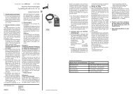
3. Spezifikation der HVI ® power-Leitung<br />
3.1 Aufbau der HVI ® power-Leitung<br />
Die HVI ® power-Leitung ist eine hochspannungsfeste, isolierte Ableitung mit einem halbleitenden<br />
Außenmantel (siehe Bild 1).<br />
Typisch ist die Anwendung als isolierte Ableitung im Blitzschutz zur Beherrschung des Trennungsabstandes<br />
nach DIN EN 62305-3 (VDE 0185-305-3). Zuerst ist die Berechnung des Trennungsabstandes “s”,<br />
wie in der Norm DIN EN 62305-3 (VDE 0185-305-3) Blitzschutz Teil 3, Abschnitt 6.3 erläutert, mit<br />
dem Ma te ri al faktor k m<br />
= 1 für Luft oder k m<br />
= 0,5 für festen Baustoff durchzuführen. Es muss geprüft<br />
werden, ob dieser errechnete Trennungsabstand mit dem äquivalenten Trennungsabstand der<br />
HVI ® power-Leitung (siehe technische Daten, Tabelle 1 und Seite 7) realisiert werden kann:<br />
errechneter Trennungsabstand ≤ äquivalenter Trennungsabstand.<br />
Ist dies nicht der Fall, dann sind die im Kapitel 6.2 auf Seite 20 beschriebenen Maßnahmen notwendig.<br />
Die Länge für die Berechnung des Trennungsabstandes “s” muss vom Kopfstück bis zur nächsten<br />
Ebene des Blitzschutz-Potentialausgleiches, z.B. Erdungsanlage, gemessen werden.<br />
Bei einer Ableitung k c =1 können somit je nach Schutzklasse des Blitschutzsystems (LPS) folgende maximale<br />
Leitungslängen realisiert werden:<br />
LPS I max. 11,25 m<br />
LPS II max. 15,0 m<br />
LPS III max. 22,5 m<br />
Halbleitender Außenmantel<br />
(Äußerer Halbleiter, schwarz)<br />
Isolationsschicht<br />
Glättungsbelag<br />
Cu-Leiter mehrdrähtig<br />
25 mm²<br />
Bild 1<br />
Aufbau der HVI ® power-Leitung<br />
6
3.2 Technische Daten<br />
Außenmantel schwarz, RAL 9011<br />
Äquivalenter<br />
Trennungsabstand der<br />
HVI ® power-Leitung<br />
Außendurchmesser<br />
minimaler Biegeradius<br />
Luft<br />
festen Baustoff<br />
Dauertemperaturbereich (bei fester Verlegung)<br />
≤ 0,9 m<br />
≤ 1,8 m<br />
27 mm<br />
270 mm<br />
-30° bis +70°C<br />
Umgebungstemperatur und Leitungstemperatur<br />
bei Verlegung und Verarbeitung<br />
max. Zugbelastung<br />
Innenleiter Kupfer mehrdrähtig<br />
-5° bis +40°C<br />
1.200 N<br />
25 mm²<br />
Tabelle 1<br />
Technische Daten HVI ® power-Leitung<br />
3.3 Chemische Eigenschaften<br />
Halogenfreiheit<br />
Brandverhalten<br />
Witterungsbeständig (UV-Beständig)<br />
Brandlast<br />
Weichmacher<br />
ja<br />
nicht selbstverlöschend<br />
ja<br />
6,4 kWh/m<br />
keine<br />
Tabelle 2<br />
Chemische Eigenschaften HVI ® power-Leitung<br />
7
4. Verfügbare Varianten<br />
Das Bauteileprogramm HVI ® power-Leitung-System besteht aus der HVI ® power-Leitung und einem<br />
auf diese Leitung abgestimmten Programm mit Anschluss- und Befestigungselementen. Bei<br />
der Planung und Anwendung der HVI ® power-Leitung sind besondere Kenntnisse erforderlich. Die<br />
HVI ® power-Leitung ist als werksseitig vorkonfektionierte Leitung oder als 100m Trommelware mit<br />
der Bezeichnung HVI ® power long verfügbar. Ergänzende Hinweise über das Bauteileprogramm des<br />
HVI ® power-Leitung-System können aus unseren Druckschriften DS.-Nr. 0210 und DS.-Nr. 0212, unserem<br />
Hauptkatalog Blitzschutz/Erdung oder unter www.dehn.de - Produktdaten entnommen werden.<br />
Grundsätzlich können alle HVI ® power-Leitungen gekürzt, jedoch nicht verlängert werden!<br />
4.1 HVI ® power-Leitung vorkonfektioniert<br />
Generell ist bei der vorkonfektionierten HVI ® power-Leitung werksseitig ein Leitungsende, wie in<br />
Tabelle 3, Seite 9 und Tabelle 4, Seite 10 dargestellt, mit entsprechender Anschlusstechnik vorkonfektioniert.<br />
Damit ist das Kopfstück fest montiert und bereits umschrumpft. Das zweite Leitungsende<br />
kann im Bedarfsfall noch gekürzt werden, um das lose mitgelieferte Anschlusselment entsprechend<br />
des Aufbaues der Anlage genau zu positionieren.<br />
Bei Bestellung der HVI ® power-Leitung ist die Leitungs-/Mindestlänge zu beachten / anzugeben. Diese<br />
Angabe ist bindend und folglich kann auf Grund der auftragsbezogenen Fertigung (Konfektionierung<br />
der Leitungslänge) die Leitung nicht zurückgenommen werden. Die vorkonfektionierte HVI ® power-Leitung<br />
ist in einer Standard-/Mindestlänge von 6 m verfügbar und kann mit 0,5 m-Schritten<br />
erhöht werden. Die Standardmindestlänge von 6 m ist für den Einsatz in Kombination mit dem 3,5 m<br />
langen Stützrohr ausgelegt. Für das Stützrohr mit 5 m Länge wird eine Mindestleitungslänge von 8 m<br />
empfohlen.<br />
Es wird lose beiliegend ein Anschlusselement, ein Schrumpfschlauch und ein Innensechskantschlüssel<br />
mitgeliefert (siehe auch Tabelle 3).<br />
Das Ablängen / Kürzen der HVI ® power-Leitung sollte mit speziellem Werkzeug (HVI ® cutter<br />
und HVI ® strip 27) und das spätere Anbringen des Anschlusselementes bzw. Schrumpfschlauches, unter<br />
Berücksichtigung der beschriebenen Anschlusstechnik, durchgeführt werden (siehe hierzu Kapitel<br />
5 ab Seite 15).<br />
8
HVI ® power-Leitung<br />
vorkonfektioniert<br />
Art.-Nr. Standard-/Mindestlänge Lieferumfang<br />
Varianten 819 160 6 m + x m<br />
(max. 22,5m bei kc = 1)<br />
• 1 Kopfstück werkseitig montiert und<br />
umschrumpft.<br />
• 1 Anschlusselement, 1 Schrumpfschlauch<br />
und 1 Innensechskantschlüssel<br />
lose beigelegt.<br />
Einsatzbereich<br />
Wird verwendet, wenn die Fangeinrichtung des Äußeren Blitzschutzes direkt mit der<br />
Erdungsanlage verbunden wird, z.B. Getrennte Fangeinrichtung an Mobilfunk-Antennen<br />
- Stützrohrinnenverlegung (siehe hierzu Bild 8, Seite 25 und Bild 9, Seite 26).<br />
Kopfstück montiert<br />
Kopfstück und HVI ® power-Leitung<br />
umschrumpft<br />
HVI ® power-Leitung mit Spezialmantel<br />
Lose beigelegt sind:<br />
- Anschlusselement<br />
- Schrumpfschlauch<br />
- Innensechskantschlüssel<br />
Tabelle 3<br />
HVI ® power-Leitung werkseitig vorkonfektioniert - Übersicht<br />
9
4.2 HVI ® power-Leitung zur Anbindung an Blitzspannung behaftete Anlagenteile<br />
Bei Anbindung der vorkonfektionierten HVI ® power-Leitung an Blitzspannung behaftete Anlagenteile<br />
(siehe Kapitel 6.2 auf Seite 20 und Kapitel 6.3 auf Seite 27) muss ein zweiter Endverschluss berücksichtigt<br />
werden. Hierzu muss ein PA-Anschlusselement (Art.-Nr. 410 239) oder ein Variables Dreibeinstativ<br />
mit PA-Element (Art.-Nr. 105 279) separat bestellt werden.<br />
HVI ® power-Leitung Art.-Nr. Standard-/<br />
Mindestlänge<br />
Varianten 819 160 6 m + x m<br />
(max. 22,5m, bei<br />
k c = 1)<br />
Lieferumfang<br />
• HVI ® power-Leitung vorkonfektioniert<br />
• 1 Kopfstück werksseitig montiert und umschrumpft.<br />
• 1 Anschlusselement, 1 Schrumpfschlauch und<br />
1 Innensechskantschlüssel lose beigelegt.<br />
410 239 PA-Anschlusselement<br />
oder 105 279 Variables Dreibeinstativ mit PA-Element<br />
Einsatzbereich<br />
Wird eingesetzt, wenn z.B. mehrere zu schützende Anlagenteile nicht einzeln, sondern<br />
gemeinsam über eine "Getrennte Ringleitung" mit der Erdungsanlage des<br />
Gebäudes verbunden werden (siehe Kapitel 6.2 auf Seite 20). Die Leitung mit<br />
einem im Stützrohr angebrachten Endverschluss und einem vor Ort zu erstellenden<br />
Endverschluss wird typisch dort verwendet, wo die Gesamtleitungslänge nicht<br />
während der Anlagenplanung exakt bestimmt werden kann.<br />
Kopfstück montiert<br />
HVI ® power-Leitung<br />
mit Spezialmantel<br />
Kopfstück und HVI ® -Leitung<br />
umschrumpft<br />
Lose beigelgt sind:<br />
- Anschlusselement<br />
- Schrumpfschlauch<br />
- Innensechskantschlüssel<br />
Separat bestellt werden muss:<br />
- PA-Anschlusselement<br />
oder<br />
- Variables Dreibeinstativ mit<br />
PA-Element<br />
Tabelle 4<br />
HVI ® power-Leitung zur Anbindung an Blitzspannung behaftete Anlagenteile - Übersicht<br />
10
4.3 HVI ® power long - Trommelware<br />
Im Auslieferungszustand ist die HVI ® power long-Leitung auf einer Einwegtrommel aufgerollt.<br />
Zu beachten ist, dass im Lieferumfang das zur Montage zwingend benötigte Anschluss-Set nicht enthalten<br />
ist. Folglich muss das Anschluss-Set und ebenso je nach Bedarf, Art und Aufbau der Anlage das<br />
bzw. die benötigten PA-Anschlusselemente separat dazu bestellt werden (siehe Tabelle 5).<br />
Allgemeines Zubehör und Werkzeuge können aus der Tabelle 6 ab Seite 12 entnommen werden.<br />
HVI ® power long Art.-Nr. Länge Lieferumfang Einsatzbereich<br />
819 137 100 m Einwegtrommel mit<br />
Außen- Ø: ca. 900 m<br />
Breite: ca. 474 mm<br />
inkl:<br />
1 Inbus-Schlüssel<br />
1 Montageanleitung<br />
Zur Konfektionierung vor Ort.<br />
819 142 Anschluss-Set:<br />
1 Kopfstück<br />
1 Anschlusselement<br />
2 Schrumpfschläuche<br />
Kopfstück und Anschlusselement<br />
zum Anschließen an die beiden<br />
Enden der HVI ® power-Leitung<br />
410 239 PA-Anschlusselement PA-Anschlusselement Ø 27 mm<br />
zum Absteuern des elektrischen<br />
Feldes im Bereich Endverschluss.<br />
Wird für den Endverschluss benötigt.<br />
105 279 Variables Dreibeinstativ<br />
mit PA-Element für<br />
den Endverschluss, einstellbare<br />
Höhe von 610<br />
bis 1095 mm (Betonsockel-Oberkante)<br />
Tabelle 5<br />
HVI ® power long - Trommelware und benötigtes Zubehör<br />
11
4.4 Benötigtes Zubehör, Werkzeuge und Montageteile<br />
Für die Montage der HVI ® power-Leitungen stehen nachfolgende Montageteile und Werkzeuge zur<br />
Verfügung:<br />
Art.-Nr. Lieferumfang Beschreibung<br />
819 142 Anschluss-Set:<br />
1 Kopfstück<br />
1 Anschlusselement<br />
2 Schrumpfschläuche<br />
275 240 Metallleitungshalter<br />
HVI ® power-Leitung<br />
Kopfstück und Anschlusselement zum Anschließen an<br />
die beiden Enden der HVI ® power-Leitung.<br />
Leitungshalter NIRO Ø 27 - 30 mm<br />
Gewinde M8<br />
275 249 Metallleitungshalter<br />
HVI ® power-Leitung<br />
Leitungshalter NIRO Ø 27 - 30 mm<br />
Gewinde M8 mit Kunststoffsockel<br />
275 241 Metallleitungshalter<br />
HVI ® power-Leitung<br />
Leitungshalter NIRO Ø 27 - 30 mm<br />
Gewinde M6<br />
275 242 Metallleitungshalter<br />
HVI ® power-Leitung<br />
Leitungshalter NIRO Ø 27 - 30 mm<br />
Langloch Ø 5,5 x 10 mm<br />
410 239 PA-Anschlusselement PA-Anschlusselement Ø 27 mm zum Absteuern des<br />
elektrischen Feldes im Bereich Endverschluss.<br />
Wird für jeden Endverschluss benötigt.<br />
597 227 HVI ® strip 27 Abisolierwerkzeug für mehrdrähtige<br />
Leitungen Ø 27 mm.<br />
Bestehend aus Handgriff und Schneidkopf<br />
597 127 HVI ® head 27 Schneidkopf Ø 27 mm<br />
für Abisolierwerkzeug HVI ® strip 27<br />
12
Art.-Nr. Lieferumfang Beschreibung<br />
597 032 HVI ® cutter Kabelschere zum Ablängen der HVI ® power-Leitung<br />
253 334 Flachdachhalter-SET zum Verlegen der Leitung auf Flachdächern<br />
Gewicht 8,5 kg<br />
202 857 Steildachhalter Strebe mit vorgeformten Biegestellen zum Verlegen<br />
der HVI ® power-Leitung auf Steildächern<br />
459 200 Trennklemme Rd/Rd<br />
Rd/Fl<br />
Trennklemme NIRO 8 - 10 / 8 - 10 mm mit Zwischenplatte<br />
für zwei Rundleiter oder 8 - 10 / 30 mm für<br />
Rund- und Flachleiter<br />
(200 kA für LPS I)<br />
105 279 Variables Dreibeinstativ mit<br />
PA-Element<br />
zum Erstellen des Endverschlusses<br />
105 344 Wandhalter für Stützrohr Wandbefestigungswinkel mit Verstellbereich<br />
von 150 - 200 mm<br />
105 160 Befestigungsschelle<br />
mit Spannband<br />
Klemmbereich 50 - 300 mm<br />
253 333 Flachdachhalter-SET zum Verlegen der Leitung auf Flachdächern<br />
Gewicht 4,6 kg<br />
Tabelle 6<br />
Zubehör und Werkzeug<br />
13
4.5 HVI ® power-Leitung Stützrohrinnenverlegung<br />
Bei den verwendeten Stützrohren für die Stützrohrinnenverlegung der HVI ® power-Leitung ist ein<br />
PA-Element in Form einer Federkontaktierung integriert.<br />
Der Stützrohrkopf ist in sich mechanisch geschlossen und daher wasserundurchlässig.<br />
Eine Überspannung von mehreren Stützrohren zur Stromaufteilung mittels Seilen ist aus statischen<br />
Gründen nur beschränkt möglich! Bitte kontaktieren Sie ggfs. für nähere Informationen das Werk.<br />
Für die Montage zur Stützrohrinnenverlegung der HVI ® power-Leitungen stehen unterschiedliche<br />
Stützrohrvarianten zur Verfügung (siehe nachfolgenden Tabelle 7:<br />
Art.-Nr.<br />
gebündelt,<br />
bestehend aus:<br />
Bauteillänge<br />
Gesamtlänge<br />
Mindestlänge<br />
HVI®power-<br />
Leitung<br />
105 320 Stützrohr 3,5 m 4,5 m 6 m + x m<br />
Fangspitze Ø 10 mm<br />
1,0 m<br />
105 321 Stützrohr 3,5 m 6,0 m 6 m + x m<br />
Fangstange Ø 22/16/10 mm<br />
2,5 m<br />
105 322 Stützrohr<br />
Fangspitze Ø 10 mm<br />
5,0 m<br />
1,0 m<br />
6,0 m 6 m + x m<br />
(empfohlene<br />
Mindestlänge<br />
8m)<br />
105 323 Stützrohr<br />
Fangstange Ø 22/16/10 mm<br />
5,0 m<br />
2,5 m<br />
7,5 m 6 m + x m<br />
(empfohlene<br />
Mindestlänge<br />
8m)<br />
Tabelle 7<br />
Stützrohrvarianten<br />
14
5. Konfektionierung der HVI ® power-Leitung<br />
5.1 Ablängen und Absetzen der HVI ® power-Leitung<br />
Das Ablängen der HVI ® power-Leitung auf die benötigte Länge kann mit dem HVI ® cutter (Kabelschere,<br />
Art.-Nr. 597 032) erfolgen. Es ist auf einen rechtwinkligen Schnitt zu achten!<br />
Zum Absetzen der HVI ® power-Leitung wird das Abisolierwerkzeug HVI ® strip 27 (Art.-Nr. 597 227)<br />
benötigt. Das Werkzeug HVI ® strip 27 ermöglicht in einfacher und sicherer Weise das Absetzen des<br />
äußeren Mantels und der PE-Isolierung ohne den darunterliegenden Cu-Leiter zu verletzen. Es kann<br />
zum Absetzen des halbleitenden Mantels und gleichzeitig der PE-Isolierung der HVI ® power-Leitung<br />
mit einem Außendurchmesser von 27 mm verwendet werden.<br />
Das Werkzeug HVI ® strip 27 besteht aus einem Handgriff und einem austauschbaren Schneidkopf.<br />
Dieser kann einzeln unter der Bezeichnung HVI ® head 27 (Art.-Nr. 597 127) nachbestellt werden. Das<br />
Ansetzen des Schneidkopfes an den Handgriff erfolgt ohne Werkzeug über eine einfache Bajonettkupplung.<br />
Die Abisolierlänge ist in Stufen (Rastpunkte) von 0,2 mm über das in dem Griff eingebaute<br />
Stellrad regulierbar, die eingestellte Länge ist auf der Skala des Handgriffes ablesbar.<br />
Die effektive Abisolierlänge stimmt mit der eingestellten Länge in einer Toleranzbreite von ± 2 mm<br />
überein (siehe hierzu Bild 2).<br />
Bei der Bedienung des HVI ® strip 27 ist wie folgt vorzugehen:<br />
ÂÂAbzusetzende Länge 35 mm am Werkzeug einstellen bzw. korrekte Einstellung kontrollieren.<br />
ÂÂWerkzeug mit Schneidkopf am abgeschnittenen Leitungsende ansetzen.<br />
ÂÂMit Drehbewegung im Uhrzeigersinn und leichter Druckausübung mittels des Werkzeuges erfolgt<br />
der Schneidevorgang / das Absetzen.<br />
!<br />
Sicherheitshinweis<br />
NICHT mit dem Finger in den Schneidkopf greifen.<br />
Verletzungsgefahr!<br />
HVI ® head 27<br />
Schneidkopf<br />
HVI ® strip 27<br />
Handgriff<br />
Stellrad<br />
Abisolierlänge<br />
HVI ® power-Leitung<br />
Bajonettkupplung<br />
Skala<br />
Bild 2 Werkzeug HVI ® head 27<br />
15
5.2 Montage von Kopfstück bzw. Anschlusselement<br />
Die Isolierung der HVI ® power-Leitung ist für die Montage von Kopfstück bzw. Anschlusselement um<br />
35 mm abzusetzen.<br />
Nach dem Absetzen der Isolierung wird das Kopfstück bzw. das Anschlusselement an den Leitungsenden<br />
der HVI ® power-Leitung montiert.<br />
Die nachfolgenden Montageschritte sind dabei zu beachten (siehe auch Bild 3):<br />
ÂÂKopfstück bzw. das Anschlusselement an die HVI ® power-Leitung heranführen und mit Rechtsdrehung<br />
auf das jeweilige Leitungsende bis zum Anschlag aufdrehen. Unterstützend kann dazu auch<br />
ein Gabelschlüssel (Schlüsselweite, SW 19) an der Schlüsselfläche des Kopfstückes bzw. dem Anschlusselement<br />
angesetzt werden.<br />
ÂÂAnschließend werden die beiden Gewindestifte (Innensechskant) mit einem Anzugsdrehmoment<br />
von 5 Nm eingeschraubt und somit der CU-Leiter der HVI ® power-Leitung sicher elektrisch (blitzstromtragfähig)<br />
verbunden.<br />
HVI ® power-Leitung<br />
mehrdrähtige Cu-Leiter<br />
35 mm<br />
Gewindestifte, beschichtet,<br />
Anzugsdrehmoment 5 Nm<br />
Kopfstück<br />
Schlüsselfläche (SW 19)<br />
Anschlusselement<br />
Schlüsselfläche (SW 19)<br />
Ø 10 mm<br />
Bild 3<br />
Montage des Kopfstückes bzw. Anschlusselementes<br />
16
5.3 Umschrumpfen<br />
Verarbeitung der Schrumpfschläuche<br />
Nach der Montage des Kopfstückes bzw. des Anschlusselementes an der HVI ® power-Leitung sind die<br />
entsprechenden Montagebereiche zu umschrumpfen. Die Umschrumpfung erfolgt zum Schutz vor mechanischen,<br />
umweltbedingten oder chemischen Einflüssen. Zum Umschrumpfen stehen zwei Schrumpfschlauchtüllen<br />
(im Lieferumfang Anschluss-Set enthalten) zur Verfügung.<br />
Beim Umschrumpfen sind nachfolgende Punkte zu beachten:<br />
ÂÂDer vorgegebene Umschrumpfungsbereich vom Kopfstück, Anschlusselement bis hin zur<br />
HVI ® power-Leitung ist einzuhalten (siehe Bild 4).<br />
ÂÂDer Schrumpfvorgang erfolgt im vorderen Umschrumpfungsbereich des jeweiligen Kopfstückes bzw.<br />
des Anschlusselementes und endet an der HVI ® power-Leitung. Die Schrumpfschlauchtüllen müssen<br />
bündig mit dem Umschrumpfungsbereich abschließen. Gegebenenfalls müssen sie während der<br />
Umschrumpfung nachpositioniert werden.<br />
ÂÂDie vorgegebene Schrumpftemperatur von max. 150 °C ist einzuhalten!<br />
ÂÂIm Umschrumpfungsbereich der HVI ® power-Leitung dürfen keine zu hohen Schrumpftemperaturen<br />
angewendet werden. Bei überhöhter Schrumpftemperatur kann der halbleitende Mantel der<br />
HVI ® power-Leitung beeinträchtigt oder zerstört werden. Die Funktionalität der HVI ® power-Leitung<br />
ist eventuell nicht mehr gewährleistet.<br />
ÂÂGenerell dürfen beim Umschrumpfen keine Lufteinschlüsse oder Blasenbildungen auftreten!<br />
Umschrumpfungsbereich<br />
Kopfstück<br />
Umschrumpfungsbereich<br />
Anschlusselement<br />
Korrekte Umschrumpfung<br />
Falsche Umschrumpfung<br />
Bild 4<br />
Umschrumpfen des Kopfstückes bzw. Anschlusselementes<br />
17
6. Montage<br />
6.1 Montage der HVI ® power-Leitung im Stützrohr<br />
Vor der Montage des Stützrohres ist die konfektionierte HVI ® power-Leitung mit montiertem Kopfstück<br />
voran in das Stützrohr einzuführen und zu befestigen (siehe hierzu auch Bild 5, Seite 19).<br />
Die nach fol gen den Mon ta ge schritte hierbei sind zu beachten:<br />
ÂÂZuerst die Arretierungsschraube Kopfstück M8 x 25 mm am Stützrohrkopf aufschrauben.<br />
ÂÂNun wird die HVI ® power-Leitung von unten in das Stützrohr eingeführt, dabei muss der Druckwiderstand<br />
der innenliegenden PA-Federkontaktierung überwunden werden. Ein mehrfaches Rein- und<br />
Rausschieben der Leitung in das Stützrohr ist möglich. Zur Kontaktierung des Kopfstückes muss die<br />
HVI ® power-Leitung bis zum oberen Anschlag des Stützrohres eingeschoben und gehalten werden.<br />
ÂÂDanach wird die Arretierungsschraube M8 x 25 mm wieder fest verschraubt und damit das Kopfstück<br />
im Stützrohr fixiert und elektrisch (blitzstromtragfähig) verbunden. Dabei ist ein Anzugsdrehmoment<br />
der Arretierungsschraube von 15 Nm zu beachten. Auf einen korrekten Abstand (ca. 7mm)<br />
des Schraubenkopfes zum Stützrohr nach dem Festziehen ist zu achten. Die Kleberbeschichtung der<br />
Schraube wird erst nach ca. 5 Minuten fest, so dass in diesem Zeitraum die Schraube korrekt positioniert<br />
und angezogen werden kann. Nach dem vollständigen Aushärten der Kleberbeschichtung muß<br />
beim wieder Entfernen der Schraube diese durch eine Neue ersetzt werden.<br />
ÂÂDie ordnungsgemäße mechanische Befestigung der HVI ® power-Leitung im Stützrohr ist zu überprüfen!<br />
(siehe Bild 5). Die korrekte Montage kann mit einem leichten Zug am Austritt der Leitung<br />
überprüft werden.<br />
ÂÂJe nach Aufbau der Anlage muss entweder vor bzw. nach der Montage des Stützrohres die entsprechende<br />
Fangspitze oder Fangstange montiert werden.<br />
  Die Fangspitze bzw. Fangstange wird von oben in den Stützrohrkopf eingeführt und mittels der<br />
beiden Arretierungsschrauben M8x16 mm bzw. M8x10 mm festgeschraubt, dabei ist ebenfalls das<br />
Anzugsdrehmoment von 15 Nm zu beachten.<br />
18
Lieferzustand Montagezustand Korrekte Montage<br />
Stützrohrkopf<br />
Fangstange<br />
ø = 22/16/10 mm<br />
wasserundurchlässig<br />
Arretierungsschraube<br />
Kopfstück, Sechskant M8 x 25 mm,<br />
Anzugsdrehmoment 15 Nm<br />
Fangspitze ø 10 mm<br />
Arretierungsschrauben<br />
Anzugsdrehmoment 15 Nm<br />
-Fangspitze 2x M8x16 mm<br />
-Fangstange 2x M8x10 mm<br />
ca.7 mm<br />
Arretierungsschraube<br />
Kopfstück<br />
(Sechskant M8 x 25 mm,<br />
Anzugsdrehmoment 15 Nm)<br />
GFK/NIRO-Stützrohr<br />
Falsche Montage<br />
ca. 13 mm<br />
ca. 0 mm<br />
HVI ® power-Leitung<br />
(Lieferzustand)<br />
Bild 5<br />
Montage des Kopfstückes im Stützrohr<br />
19
6.2 Endverschluss<br />
Im Bereich des End ver schlus ses ist der<br />
errechnete Tren nungs abstand "s" zu<br />
elektrisch leitfähigen bzw. geerdeten<br />
Teilen ein zuhalten.<br />
Im Bereich des End verschlusses, z.B.:<br />
ÂÂam Stützrohr zwischen Kopfstück und PA-Anschlusselement<br />
(siehe 6.2.1, Seite 20).<br />
ÂÂvariabler Endverschluss an Ringleitung/Attika<br />
(siehe 6.2.2, Seite 23)<br />
ÂÂEndverschluss an einer Gebäudestruktur zwischen<br />
PA-Anschlusselement und Erdanschlusselement<br />
dürfen keine elek trisch leitfähigen<br />
oder geerdeten Teile wie, z.B. metallene Leitungs<br />
halter, Kon struk tionsteile, Ar mierung usw.<br />
angeordnet sein (siehe 6.2.3, Seite 26).<br />
6.2.1 Bereich des Endverschlusses am<br />
Stützrohr am Beispiel einer Antennenanwendung<br />
Der Bereich des Endverschlusses erstreckt sich<br />
vom Anschluss des Kopfstückes bis zu dem im<br />
Stützrohr integrierten PA-Federelement (siehe Bild<br />
6, Detail A und B) und kann von außen betrachtet<br />
über den gesamten Verlauf des GFK-Rohres angenommen<br />
werden.<br />
Über die mechanische Federkontaktierung des<br />
PA-Elements an die HVI ® power-Leitung (halbleitender<br />
Spezialmantel) erfolgt die Absteuerung<br />
gegen das Bezugspotential durch Kontaktierung<br />
der HVI ® power-Leitung an das Stützrohr. Zur Absteuerung<br />
ist eine elektrisch leitende Verbindung<br />
des Stützrohres zum nächstgelegenen Potentialausgleich<br />
der Anlage zwingend erforderlich.<br />
Anschluss<br />
Kopfstück<br />
Detail A<br />
Abgriff<br />
PA-Element<br />
Detail B<br />
Verbindung zum<br />
Potentialausgleich<br />
der Anlage<br />
Detail A:<br />
Anschluss Kopfstück<br />
α<br />
α<br />
s<br />
Anschluss an die<br />
Erdungsanlage<br />
Bereich<br />
Endverschluss<br />
hergestellt (mechanische und elektrische Verbindung).<br />
Antennenstandrohr<br />
Bandrohrschelle<br />
Stützrohr<br />
HVI ® power-Leitung<br />
Detail B:<br />
PA-Element<br />
mechanische Federkontaktierung<br />
Die leitende Verbindung zwischen dem Stützrohr<br />
und dem metallischem Antennenstandrohr wird<br />
z.B. über die Bandrohrschelle (Art.-Nr. 105 360)<br />
Bild 6<br />
Bereich des Endverschlusses im Stützrohr<br />
20
Für den Anschluss des Antennenstandrohres an den Potentialausgleich (Funktionspotentialausgleich)<br />
kann z.B. die Antennenbandrohrschelle (Art.-Nr. 540 100) verwendet werden.<br />
Variante - HVI ® power-Leitung Stützrohrinnenverlegung/Bandrohrschelle an "Mobilfunk-Antenne"<br />
Schutzwinkel α<br />
nach DIN EN 62305-3 (VDE 0185-305-3)<br />
Blitzschutz Teil 3, Tabelle 2<br />
z.B. Fangspitze<br />
NIRO, Ø = 10 mm, L = 1000 mm<br />
Art.-Nr. 101 001<br />
α α<br />
s<br />
Bereich<br />
Endverschluss<br />
1800 mm<br />
z.B. Antenne<br />
Stützrohr GFK/NIRO, z.B. Art.-Nr. 105 320<br />
Stützrohr L = 3500 mm<br />
z.B. Bandrohrschelle<br />
NIRO, Art.-Nr. 105 360,<br />
Klemmbereich Rohr Ø = 50-300 mm<br />
Hinweis:<br />
Antennenerdung nach<br />
DIN VDE 0855 beachten!<br />
HVI ® power-Leitung<br />
Erdanschlusselement<br />
Verbindung zum Potentialausgleich<br />
des Gebäudes<br />
Erdungsanlage<br />
Bild 7<br />
Getrennte Fangeinrichtung mit HVI ® power-Leitung an Mobilfunk-Antenne - Bandrohrschelle<br />
21
Variante - HVI ® power-Leitung Stützrohrinnenverlegung / Wandhalter<br />
Schutzwinkel α<br />
nach DIN EN 62305-3 (VDE 0185-305-3)<br />
Blitzschutz Teil 3, Tabelle 2<br />
α<br />
α<br />
z.B. Fangstange<br />
NIRO, Ø = 22/16/10 mm, L = 2500 mm<br />
Art.-Nr. 103 239<br />
s<br />
Bereich<br />
Endverschluss<br />
1800 mm<br />
Stützrohr mit gebündelter Fangstange<br />
GFK/NIRO, z.B. Art.-Nr. 105 321<br />
Stützrohr L = 3500 mm + Fangstange L = 2500 mm<br />
z.B. Wandbefestigungswinkel<br />
NIRO, Klemmbereich Stützrohr Ø = 40-50 mm,<br />
mit Doppelüberleger, Art.-Nr. 105 344<br />
Doppelüberleger für PA-Anschluss<br />
für den Anschluss von 2x Rd 8-10 mm<br />
HVI ® power-Leitung<br />
Erdungsanlage<br />
Erdanschlusselement<br />
Verbindung zum<br />
Potentialausgleich<br />
des Gebäudes<br />
Bild 8<br />
Getrennte Fangeinrichtung mit HVI ® power-Leitung und Wandhalterung<br />
22
6.2.2 Variabler Endverschluss<br />
Wird die HVI ® power-Leitung nicht bis zur Erdungsanlage, sondern an Blitzspannung behaftete Teile,<br />
(z.B. Attika, Ringleitung) angeschlossen, ist für die effektive Länge des Endverschlusses nachfolgende<br />
Tabelle 8 ausschlaggebend (siehe auch Bild 9, Seite 24 und Bild 10, Seite 25).<br />
Im Bereich unterhalb des Trennungsabstandes "s" 17,5 cm (in Luft) am Erdanschlusselement sind keine<br />
besonderen Montageanforderungen relevant (direkter Anschluss).<br />
Bedingt durch den Leitungsverlauf der HVI ® power-Leitung und des dadurch reduzierten Trennungsabstandes<br />
ist die Realisierung eines zweiten Endverschlusses oberhalb von "s" ≥ 75 cm (in Luft) nicht<br />
üblich.<br />
Länge<br />
Variabler Endverschluss (cm)<br />
200<br />
180<br />
150<br />
maximum<br />
HVI ® power-Leitung<br />
max. variabler Endverschluss<br />
HVI ® power-Leitung<br />
100<br />
35<br />
10 17.5<br />
50<br />
75<br />
90<br />
ÄquivalenterTrennungsabstand<br />
"s" (in Luft)<br />
Tabelle 8<br />
Variabler Endverschluss<br />
23
Variabler Endverschluss an "Getrennte Ringleitung" / Attika<br />
Bei mehreren zu schützenden Anlagenteilen ist es sinvoll, die HVI ® power-Leitung nicht einzeln von<br />
jeder Fangeinrichtung zur Erdungsanlage zu führen. Die von der Fangeinrichtung kommenden<br />
HVI ® power-Leitungen können z.B. an eine "Getrennte Ringleitung oder Attika" an ge schlos sen werden.<br />
Von dieser "Getrennten Ringleitung (Attika)" können dann mehrere Ableitungen zur Erdungsanlage<br />
geführt werden. Dies bewirkt eine Reduzierung des Strom auf tei lungs ko effizienten k C<br />
ab der Höhe<br />
der "Getrennten Ringleitung". Der Trennungsabstand "s" wird dadurch kleiner. Für diese Anwendung<br />
ist die HVI ® power-Leitung vorkonfektioniert oder HVI ® power long vorgesehen (siehe Bild 9 und<br />
10).<br />
Die "Getrennte Ringleitung" muss z.B. auf der Dachebene unter Berücksichtigung des er rech neten<br />
Tren nungs abstandes "s" auf Distanzhaltern und Betonsockel verlegt werden.<br />
Anschlusselement<br />
Variabler Endverschluss<br />
350 mm - max. 1800 mm<br />
HVI ® power-Leitung<br />
Getrennte Ringleitung<br />
Distanzhalter<br />
s<br />
Variables<br />
Dreibeinstativ<br />
mit PA-Element<br />
Leitungshalter<br />
z.B. Art.-Nr. 253 333<br />
Variables Dreibeinstativ<br />
mit PA-Element<br />
Art.-Nr. 105 279<br />
Verbindung zum<br />
Potentialausgleich<br />
des Gebäudes<br />
Bild 9<br />
Getrennte Ringleitung mit HVI ® power-Leitung<br />
24
Variabler Endverschluss<br />
350 mm - max. 1800 mm<br />
Anschlusselement<br />
s<br />
Attika<br />
HVI ® power-Leitung<br />
Leitungshalter<br />
Art.-Nr. 253 333<br />
Variables<br />
Dreibeinstativ<br />
mit PA-Element<br />
Bild 10 Attika<br />
Variables Dreibeinstativ<br />
mit PA-Element<br />
Art.-Nr. 105 279<br />
Verbindung zum<br />
Potentialausgleich<br />
des Gebäudes<br />
25
6.2.3 Endverschluss an einer Gebäudestruktur<br />
Wird die HVI ® power-Leitung an einer Gebäudestruktur verlegt, ist der errechnete Trennungsabstand<br />
"s" im Endverschlussbereich zu den in der Gebäudestruktur befindlichen Metallteilen einzuhalten.<br />
Der Bereich des Endverschlusses erstreckt sich vom PA-Anschlusselement bis zum Anschluss des Erdanschlusselementes<br />
(siehe Bild 11).<br />
Über die mechanische Kontaktierung des PA-Elementes (halbleitender Spezialmantel) erfolgt die Absteuerung<br />
gegen das Bezugspotential. Zur Absteuerung ist eine elektrisch leitende Verbindung zum<br />
nächstgelegenen Potentialausgleich (Potentialausgleichsebene) der Anlage zwingend erforderlich.<br />
Der Anschluss des Erdanschlusselementes der HVI ® power-Leitung erfolgt an die Erdungsanlage mit<br />
einer UNI-Trennklemme (Art.-Nr. 459 200, 200 kA).<br />
Detail A:<br />
PA-Element<br />
PA-Anschlusselement<br />
Detail A<br />
(Art.-Nr. 410 239)<br />
Verbindung zum<br />
Potentialausgleich<br />
der Anlage<br />
PA<br />
Halter, z.B.<br />
Art.-Nr. 275 249<br />
Detail B:<br />
Anschluss Erdanschlusselement<br />
HVI ® power-Leitung<br />
Gebäudestruktur<br />
Bereich<br />
Endverschluss<br />
35 cm -1800 mm<br />
Erdanschlusselement<br />
Detail B<br />
s<br />
s<br />
Ableitung<br />
Anschluss an die<br />
Erdungsanlage<br />
Trennklemme<br />
Art.-Nr. 459 200<br />
Bild 11 Bereich des Endverschlusses an einer Gebäudestruktur<br />
26
Besonders beachtet werden muss:<br />
ÂÂVor der Montage des PA-Anschlusselementes (Art.-Nr. 410 239) ist die HVI ® power-Leitung an der<br />
schwarzen Oberfläche zu säubern.<br />
ÂÂDie Oberfläche muss glatt und fettfrei sein.<br />
ÂÂEventuell vorhandenes Fett muss durch einen mit dem Spezialreiniger (Art.-Nr. 297 199) getränkten<br />
Lappen entfernt werden.<br />
ÂÂDas PA-Anschlusselement darf nicht verschmutzt sein.<br />
ÂÂDie Schraube des PA-Anschlusselementes ist mit einem Dreh moment von 10 Nm anzuziehen.<br />
ÂÂDas PA-Anschlusselement muss die HVI ® power-Leitung fest umschließen.<br />
6.3 Verlegung der HVI ® power-Leitung<br />
Die HVI ® power-Leitung muss in ihrem gesamten Leitungsverlauf im Schutzbereich einer Fang einrich<br />
tung des Äußeren Blitzschutzes verlegt werden. Sie darf im gesamten Leitungsverlauf nicht mit<br />
Blitzspannung behafteten Teilen der Fang ein richtung, Ableitung oder Gebäudekonstruktionsteilen in<br />
Verbindung kommen. Von dieser Festlegung kann abgewichen werden, wenn der Trennungsabstand<br />
"s" am Kreu zungs punkt der HVI ® power-Leitung mit dem Blitzspannung behafteten Teil (Fangeinrichtung,<br />
Attika oder Ableitung) ≤ 35 cm (in Luft) oder ≤ 70 cm (im festen Baustoff) ist. In diesem<br />
Fall ist eine Verbindung zwischen dem Mantel der HVI ® power-Leitung und dem mit Blitzspannung<br />
behafteten Teil zulässig (rückwärtige Spannungsfestigkeit).<br />
Die HVI ® power-Leitung muss bei der Verlegung nach dem Bereich Endverschluss in Abständen von<br />
≤ 1m befestigt werden. Die dabei verwendeten Befestigungsschrauben der metallenen Leitungshalter<br />
sind mit max. 5 Nm anzuziehen.<br />
Wird die HVI ® power-Leitung in einer baulichen Anlage verlegt, sind bauseits festgelegte Schutzmaßnahmen<br />
z.B. Brandschottungen zu beachten.<br />
27
6.4 Montage unter Berücksichtigung der Windzone / Windgeschwindigkeit<br />
Bei der Errichtung von Fangeinrichtungen müssen die Windzonen berücksichtigt werden (siehe<br />
Bild 12 und Bild 13, Seite 29). Die Windzonen sind regional unterschiedlich. Bei Errichtungen von Fangeinrichtungen<br />
außerhalb des Bundesgebietes sind die entsprechenden landesspezifischen Angaben zu<br />
den Windzonen / Windgeschwindigkeit zu berücksichtigen.<br />
Windzone 1<br />
Windzone 2<br />
Windzone 3<br />
Windzone 4<br />
Kiel<br />
Rostock<br />
Schwerin<br />
Hamburg<br />
Bremen<br />
Hannover<br />
Potsdam<br />
Magdeburg<br />
Berlin<br />
Windzone<br />
Grundgeschwindigkeit<br />
Böenwindgeschwindigkeit<br />
WZ 1 22,5 m/s 128 km/h<br />
WZ 2 25,0 m/s 142 km/h<br />
WZ 3 27,5 m/s 156 km/h<br />
WZ 4 30,0 m/s 170 km/h<br />
Essen<br />
Dortmund<br />
Düsseldorf<br />
Köln<br />
Bonn<br />
Erfurt<br />
Halle<br />
Leipzig<br />
Dresden<br />
Chemnitz<br />
Wiesbaden<br />
Frankfurt<br />
Würzburg<br />
Saarbrücken<br />
Mannheim<br />
Nürnberg<br />
Stuttgart<br />
Regensburg<br />
Augsburg<br />
Freiburg<br />
München<br />
Bild 12 Windzonen in Deutschland (Quelle: DIN EN 1991-1-4/NA, Anhang NA.A: Windzonenkarte)<br />
In die Berechnung der tatsächlichen zu erwartenden Windlastbeanspruchung geht neben der zonenabhängigen<br />
Windlast auch die Gebäudehöhe und die örtlichen Gegebenheiten (Gebäude einzeln stehend,<br />
im offenen Gelände oder eingebettet in andere Bebauung) mit ein.<br />
Bei der Auslegung freistehender Fangstangen müssen aus Sicht der Windlastbeanspruchung folgende<br />
Anforderungen erfüllt werden:<br />
ÂÂSicherheit der Fangstange gegen Kippen.<br />
ÂÂSicherheit gegen Bruch der Stangen<br />
ÂÂEinhalten des notwendigen Trennungsabstandes zum zu schützenden Objekt auch unter Windlast<br />
(Vermeidung unzulässiger Durchbiegungen)<br />
Deshalb müssen je nach Bauart der Anlage die einzelnen Komponenten wie z.B. Fangstange, Stützrohr,<br />
Dreibeinstativ usw., hinsichtlich der Windgeschwindigkeiten, richtig ausgewählt werden.<br />
28
Bei der direkten Befestigung der Fangspitze bzw. Fangstange am Stützrohr können unterschiedliche<br />
Windgeschwindigkeiten standgehalten werden. Die entsprechenden Befestigungsmaße des Stützrohres,<br />
siehe Bild 13, müssen eingehalten werden.<br />
Es ergeben sich folgende Varianten, bei denen entsprechende Windgeschwindigkeiten beherrscht werden<br />
können:<br />
ÂÂVariante I (Fangspitze Ø 10 mm, L= 1000 mm) - bis Windzone IV<br />
ÂÂVariante II (Fangstange Ø 22/16/10 mm, L = 2500 mm) - bis Windzone II<br />
Variante I<br />
Stützrohr mit Fangspitze,<br />
Art.-Nr. 105 320 / 105 322, NIRO, ø 10 mm, L = 1000 mm<br />
Variante II<br />
Stützrohr mit Fangstange,<br />
Art.-Nr. 105 321 /105 323, NIRO, ø 22/16/10 mm, L = 2500 mm<br />
α<br />
α<br />
2500 mm<br />
1000 mm<br />
α<br />
α<br />
Stützrohr GFK/NIRO<br />
≤ 2,5 m<br />
≤ 2,5 m<br />
Antenne<br />
≥ 0,5 m<br />
≥ 0,5 m<br />
Antennenmast<br />
Verbindung zum<br />
Potentialausgleich<br />
des Gebäudes<br />
Erdungsanlage<br />
Bild 13 Windgeschwindigkeit - Variante I und II bei der Befestigung am Stützrohr<br />
29
7. Checkliste für HVI ® Installation<br />
Wenn die Fragestellungen in der unten angeführten Checkliste alle mit "JA" beantwortet werden<br />
können, kann von einer ordnungsgemäßen Montage der HVI ® power-Leitung ausgegangen werden.<br />
Die Tabelle kann im Download-Bereich von <strong>DEHN</strong> + SÖHNE GmbH + Co.KG heruntergeladen werden<br />
Checkliste für HVI ® -Installation<br />
Anschrift Prüfobjekt:<br />
Name _____________________________________________________________________________________<br />
Ansprechpartner _____________________________________________________________________________<br />
PLZ, Ort, Straße ______________________________________________________________________________<br />
Telefon ____________________________________________________________________________________<br />
Pos.<br />
Fragestellung<br />
1 Ist die gesamte Anlage im einschlaggeschützten Bereich der Getrennten Fangeinrichtung?<br />
2 Liegt die Berechnung des Trennungsabstandes vor?<br />
(Ableitung bis Erdungsanlage, Insellösung mit Anbindung an bestehende Äußere<br />
Blitzschutzanlage oder Blitzschutz-Potential-Ausgleichsebene auf Dachniveau)<br />
3 Wird für die Anwendung der HVI ® Leitung der von <strong>DEHN</strong> + SÖHNE maximal spezifizierte<br />
äquivalente Trennungsabstand eingehalten?<br />
HVI ® light-Leitung / <strong>DEHN</strong>con H s ≤ 0,45 m in Luft s ≤ 0,9 m fester Baustoff<br />
HVI ® Leitung s ≤ 0,75 m in Luft s ≤ 1,5 m fester Baustoff<br />
HVI ® power-Leitung s ≤ 0,9 m in Luft s ≤ 1,8 m fester Baustoff<br />
Bewertung<br />
JA NEIN<br />
4 Ist im Bereich des Endverschlusses der errechnete Trennungsabstand eingehalten<br />
(fiktive Reuse)?<br />
5 Ist das Stützrohr und ggfs. das PA-Anschlusselement des Endverschlusses korrekt,<br />
nur mit dem Potentialausgleich / der Blitzschutz-Potential-Ausgleichsebene der<br />
Anlage, verbunden?<br />
6 Ist bei parallel geführten HVI ® Leitungen der Mindestabstand von 0,2 m zueinander<br />
eingehalten und der Anschluss an gegenüberliegende Ableitungen beachtet<br />
worden?<br />
7 Ist der minimale Biegeradius eingehalten?<br />
HVI ® light-Leitung (dunkelgrauer Außenmantel) 200 mm<br />
HVI ® Leitung (schwarzer Außenmantel) 200 mm<br />
HVI ® Leitung (grauer Außenmantel)<br />
230 mm<br />
HVI ® power-Leitung (schwarzer Außenmantel) 270 mm<br />
8 Ist das PA-Element des Endverschlusses an der halbleitenden Schicht (nicht grauer<br />
Mantel) kontaktiert?<br />
9 Ist bei Verlegung der HVI ® Leitung im Ex-Bereich die ergänzende Information der<br />
<strong>DEHN</strong>-Montageanleitung Nr. 1501 eingehalten worden?<br />
<strong>DEHN</strong>-Formblatt Nr. 2848/0613<br />
__________________________________<br />
Ort<br />
_________________________<br />
Datum<br />
______________________________________________________________<br />
Unterschrift des Prüfers<br />
Firma<br />
Bild 14 Checkliste<br />
30
Überspannungsschutz <strong>DEHN</strong> + SÖHNE Hans-Dehn-Str. 1 Tel. +49 9181 906-0<br />
Blitzschutz/Erdung GmbH + Co.KG. Postfach 1640 Fax +49 9181 906-1100<br />
Arbeitsschutz 92306 Neumarkt info@dehn.de<br />
<strong>DEHN</strong> schützt. Germany www.dehn.de
Lightning protection/earthing<br />
Installation instructions<br />
HVI ® power<br />
HVI ® power long<br />
DE GB<br />
www.dehn.de<br />
Publication No. 1829 / Update 07.13 Id No. 067426 © Copyright 2013 <strong>DEHN</strong> + SÖHNE
CONTENTS<br />
1. Application of HVI ® power Conductors......................................................................... 4<br />
2. Safety instructions........................................................................................................ 4<br />
3. Specification of HVI ® power Conductors...................................................................... 6<br />
3.1 Design of HVI ® power Conductors................................................................................ 6<br />
3.2 Technical data............................................................................................................... 7<br />
3.3 Chemical properties...................................................................................................... 7<br />
4. Different types of HVI ® power Conductors................................................................... 8<br />
4.1 Pre-assembled HVI ® power Conductors........................................................................ 8<br />
4.2 HVI ® power Conductors for parts of an installation carrying lightning voltage......... 10<br />
4.3 HVI ® power long on a drum......................................................................................... 11<br />
4.4 Required accessories, tools and mounting parts........................................................ 12<br />
4.5 HVI ® power Conductors integrated in the supporting tube........................................ 14<br />
5. Assembly of HVI ® power Conductors.......................................................................... 15<br />
5.1 Cutting HVI ® power Conductors to length/stripping HVI ® power Conductors............ 15<br />
5.2 Mounting the head piece/connection element........................................................... 16<br />
5.3 Wrapping a heat shrinkable sleeve around the head piece/connection element...... 17<br />
6. Installation.................................................................................................................. 18<br />
6.1 Installing HVI ® power Conductors in the supporting tube......................................... 18<br />
6.2 Sealing end................................................................................................................. 20<br />
6.2.1 Sealing end range of the supporting tube based on the example of an antenna.........................20<br />
6.2.2 Variable sealing end.................................................................................................................23<br />
6.2.3 Sealing end on a building’s structure.........................................................................................26<br />
6.3 Installing HVI ® power Conductors............................................................................... 27<br />
6.4 Installation with regard to the wind zone/wind speed.............................................. 28<br />
2
7. Checklist for installing HVI ® Conductors..................................................................... 30<br />
3
1. Application of HVI ® power Conductors<br />
To avoid dangerous flashover between parts of the external lightning protection system and internal<br />
installations such as conductive parts (electrical installation, pipework, etc.), the separation distance<br />
"s" must be observed when installing lightning protection systems.<br />
High impulse voltages cause flashover on the surface of insulating material if no additional measures<br />
are taken. This effect is also referred to as creeping flashover. If the creeping discharge inception voltage<br />
is exceeded, a surface discharge is initiated which can easily flash over a distance of several metres.<br />
To prevent creeping discharges, HVI ® power Conductors feature a special outer sheath which allows<br />
to discharge high lightning impulse voltages to a reference potential. For functional reasons, a connection<br />
is established between the semiconductive outer sheath and the equipotential bonding system of<br />
the building (no lightning voltage) in the sealing end range. This connection to the functional equipotential<br />
bonding can made e.g. on earthed metal roof-mounted structures located in the protected zone<br />
of the lightning protection system, earthed parts of the building construction that do not carry lightning<br />
voltage or on the protective conductor of the low-voltage system.<br />
No conductive or earthed parts may be located in the sensitive sealing end range within the separation<br />
distance "s".<br />
2. Safety instructions<br />
ÂÂHVI ® power Conductors may only be installed under the conditions shown and referred to in these<br />
installation instructions.<br />
ÂÂOnly qualified and trained personnel (lightning protection specialists) may install HVI ® power Conductors.We<br />
recommend to visit a special training course on HVI ® products help by <strong>DEHN</strong>+SÖHNE.<br />
ÂÂFor safety reasons, installation work must be stopped as soon as a thunderstorm approaches/is<br />
noticed.<br />
The components of the HVI ® power system have been tested as a complete system. Mixing components<br />
of the HVI ® power system with components from other manufacturers is not permitted.<br />
  Prior to installation, HVI ® power Conductors must be examined for good order and condition. If<br />
damage or any other defect is found, the HVI ® power Conductors must not be installed. The black<br />
sheath of HVI ® power Conductors must not be damaged by compressive deformation or cuts.<br />
4
ÂÂWhen using HVI ® power Conductors in potentially explosive atmospheres, fire and explosion protection<br />
measures must be taken.<br />
ÂÂIf HVI ® power Conductors are installed on thatched roofs (e.g. reed, straw), special installation<br />
conditions have to be observed for these flammable locations. In our Lightning Protection/Earthing<br />
main catalogue (HVI Lightning Protection for Thatched Roofs), the special installation conditions for<br />
HVI Conductors are described. These conditions also apply to HVI ® power Conductors.<br />
ÂÂIf the supporting tube is led through a roof, the roof must be properly sealed. Warm roofs must be<br />
properly sealed and insulated.<br />
ÂÂHVI ® power Conductors are suitable for outdoor use and can be installed downstream of the sealing<br />
end e.g. on roofs, in walls, in concrete or on facades/facade constructions. However, the conductors<br />
are not suitable for permanent exposure to moisture. HVI ® power Conductors with black<br />
sheath must not be installed in the soil.<br />
ÂÂSoiled HVI ® power Conductors can be cleaned with a cloth soaked with a special cleaning agent<br />
(Part No. 297 199). To be able to comply with dangerous goods regulations, this product is only<br />
transported within Germany and Austria. ISOPROPYL ALCOHOL (99.1 to 99.9 %) (CSA No. 67-63.0)<br />
can be used as an alternative!<br />
ÂÂHVI ® power Conductors must not be painted due to the special design of the outer sheath.<br />
ÂÂThe function of HVI ® power Conductors is to maintain the separation distance. Due to their design,<br />
they do not have a magnetic shielding effect. Induction effects in secondary conductors/loops must<br />
be observed. If required, surge protection measures have to be taken.<br />
ÂÂFor application-specific questions, please contact the relevant sales team or the <strong>DEHN</strong> representative<br />
in your country.<br />
  It has not yet been checked whether HVI ® power Conductors are suitable for installation in hazardous<br />
areas. Therefore, it is not allowed to use HVI ® power Conductors in these areas.<br />
5
3. Specification of HVI ® power Conductors<br />
3.1 Design of HVI ® power Conductors<br />
HVI ® power Conductors are high-voltage-resistant, insulated down conductors with a semiconductive<br />
outer sheath (see Figure 1).<br />
They are typically used as insulated down conductors of lightning protection systems to maintain the<br />
separation distance in accordance with IEC 62305 Part 3. At first, the separation distance “s”must<br />
be calculated as described in subclause 6.3 of IEC 62305 Part 3, with a material factor k m<br />
= 1 in air,<br />
or k m<br />
= 0,5 for solid material. It must be checked whether this calculated separation distance can be<br />
implemented by means of the equivalent separation distance of the HVI ® power Conductors (see<br />
technical data, Table 1 and page 7):<br />
calculated separation distance ≤ equivalent separation distance.<br />
If this is not the case, measures according to 6.2, page 20 are required.<br />
The length required for calculating the separation distance “s” is measured from the head piece to<br />
the next lightning equipotential bonding level, e.g. the earth-termination system.<br />
In case of a down conductor with k c =1, the following maximum conductor lengths are permitted depending<br />
on the class of LPS:<br />
LPS I max. 11.25 m<br />
LPS II max. 15.0 m<br />
LPS III max. 22.5 m<br />
Semiconductive outer sheath<br />
(outer semiconductor, black)<br />
Insulating layer<br />
Smoothing layer<br />
Stranded copper<br />
conductor (25 mm²)<br />
Figure 1<br />
Design of HVI ® power Conductors<br />
6
3.2 Technical data<br />
Outer sheath black, RAL 9011<br />
Equivalent separation<br />
distance of the<br />
HVI ® power Conductor<br />
Outer diameter<br />
Minimum bending radius<br />
Air<br />
Solid material<br />
Permanent temperature range (in case of fixed installation)<br />
≤ 0.9 m<br />
≤ 1.8 m<br />
27 mm<br />
270 mm<br />
-30° to +70°C<br />
Ambient temperature and conductor temperature<br />
during installation and processing<br />
Maximum tensile load<br />
Stranded inner conductor made of copper<br />
-5° to +40°C<br />
1.200 N<br />
25 mm²<br />
Table 1<br />
Technical data of HVI ® power Conductors<br />
3.3 Chemical properties<br />
Halogen-free<br />
Reaction to fire<br />
Weather-proof (UV-resistant)<br />
Fire load<br />
Diluents<br />
yes<br />
not self-extinguishing<br />
yes<br />
6.4 kWh/m<br />
none<br />
Table 2<br />
Chemical properties of HVI ® power Conductors<br />
7
4. Different types of HVI ® power Conductors<br />
The component range of the HVI ® power Conductors system consists of HVI ® power Conductors<br />
and a range of connection and fixing elements matched to these conductors. Special know-how is<br />
required to design and install HVI ® power Conductors. HVI ® power Conductors are available as<br />
pre-assembled conductors or on a 100 m drum (HVI ® power long). More information on the component<br />
range of the HVI ® power Conductors system can be found in our brochures 210 and 212, our<br />
Lightning Protection/Earthing main catalogue and at www.dehn-international.com.<br />
As a basic principle, all HVI ® power Conductors can be shortened, but not extended!<br />
4.1 Pre-assembled HVI ® power Conductors<br />
In general, one conductor end of the pre-assembled HVI ® power Conductors is fitted with the relevant<br />
connection element as shown in Table 3, page 9 and Table 4, page 10. Thus, the head piece is fixed and<br />
a heat shrinkable sleeve is wrapped around it. If required, the second conductor end can be shortened<br />
to exactly match the loose connection element to the design of the installation.<br />
When ordering HVI ® power Conductors , the conductor/minimum length must be observed/indicated.<br />
This information is binding. Since the conductors are tailored to customer needs (customised conductor<br />
lengths), conductors cannot be returned. Pre-assembled HVI ® power Conductors are available with a<br />
standard/minimum length of 6 m. Customised conductors can be ordered in 0.5 m steps. The standard/<br />
minimum length of 6 m must be used in combination with a 3.5 m long supporting tube. A minimum<br />
conductor length of 8 m is recommended for a 5 m long supporting tube.<br />
A loose connection element, heat shrinkable sleeve and hexagon socket wrench are included in delivery<br />
(see also Table 3).<br />
Special tools (HVI ® cutter and HVI ® strip 27) should be used to cut HVI ® power Conductors to<br />
length /shorten HVI ® power Conductors and the connection element/heat shrinkable sleeve should<br />
be attached considering the relevant connection method (see 5., from page 15).<br />
8
Pre-assembled<br />
HVI ® power Conductor<br />
Part.-No.<br />
Standard/minimum<br />
length<br />
Delivery includes<br />
Types 819 160 6 m + x m<br />
(max. 22.5m in case of<br />
kc = 1)<br />
• 1 fixed head piece with heat shrinkable<br />
sleeve.<br />
• 1 connection element, 1 heat shrinkable<br />
sleeve and 1 hexagon socket<br />
wrench (loose).<br />
Field of application<br />
Whenever the air-termination system of the external lightning protection system<br />
is directly connected to the earth-termination system, e.g. isolated air-termination<br />
system of mobile phone antennas - Conductor integrated in the supporting tube (see<br />
Figure 8, page 25 and Figure 9, page 26).<br />
Fixed head piece<br />
Head piece and HVI ® power Conductor<br />
with heat shrinkable sleeve<br />
HVI ® power Conductor with special<br />
sheath<br />
Loosely:<br />
- Connection element<br />
- Heat shrinkable sleeve<br />
- Hexagon socket wrench<br />
Table 3<br />
Pre-assembled HVI ® power Conductors - Overview<br />
9
4.2 HVI ® power Conductors for parts of an installation carrying lightning voltage<br />
A second sealing end is required to connect the pre-assembled HVI ® power Conductor to parts of an<br />
installation carrying lightning voltage (see 6.2, page 20 and 6.3, page 27). To this end, an equipotential<br />
bonding connection element (Part No. 410 239) or a variable tripod with equipotential bonding element<br />
(Part No. 105 279) must be ordered separately.<br />
HVI ® power Conductor Part No Standard/minimum<br />
length<br />
Delivery includes<br />
Types 819 160 6 m + x m<br />
(max. 22.5m in<br />
case of k c = 1)<br />
• Pre-assembled HVI ® power Conductor<br />
• 1 fixed head piece with heat shrinkable sleeve.<br />
• 1 connection element, 1 heat shrinkable sleeve<br />
and 1 hexagon socket wrench (loose).<br />
410 239 Equipotential bonding connection<br />
or 105 279 Variable tripod with equipotential bonding<br />
element<br />
Field of application<br />
For connecting e.g. several parts of an installation to be protected jointly to the<br />
earth-termination system of the building via an "isolated ring conductor" (see 6.2<br />
on page 20). Conductors with a sealing end in the supporting tube and a sealing<br />
end to be adjusted on site are typically used whenever the total condutor length<br />
cannot be exactly determined at the design stage of the installation.<br />
Fixed head piece<br />
HVI ® power Conductor<br />
with special sheath<br />
Head piece and<br />
HVI ® power Conductor<br />
with heat shrinkable sleeve<br />
Loosely delivered:<br />
- Connection element<br />
- Heat shrinkable sleeve<br />
- Hexagon socket wrench<br />
To be ordered separately:<br />
- Equipotential bonding<br />
connection element<br />
or<br />
- Variable tripod with equipotential<br />
bonding element<br />
Table 4<br />
HVI ® power Conductor for parts of an installation carrying lightning voltage - Overview<br />
10
4.3 HVI ® power long on a drum<br />
When delivered, the HVI ® power long Conductor is reeled up on a disposable drum.<br />
It must be observed that the required connection set is not included in delivery.<br />
Consequently, the connection set and the required equipotential bonding connection element(s) depending<br />
on the requirements, type and construction of the installation must be ordered separately (see<br />
Table 5).<br />
General accessories and tools are listed in Table 6, page 12.<br />
HVI ® power long Part No Length Delivery includes Field of application<br />
819 137 100 m Disposable drum with<br />
an outer diameter of<br />
approximately 900 m<br />
Width: approximately<br />
474 mm.<br />
1 Allen key and installation<br />
instructions<br />
819 142 Connection set:<br />
1 head piece<br />
1 connection element<br />
2 heat shrinkable<br />
sleeves<br />
For on-site assembly.<br />
Head piece and connection<br />
element to be connected<br />
to both ends of the<br />
HVI ® power Conductor<br />
410 239 Equipotential bonding<br />
connection element<br />
Equipotential bonding connection<br />
element (Ø 27 mm) for resetting<br />
the electrical field in the<br />
sealing end range. Required for<br />
the sealing end.<br />
105 279 Variable tripod with<br />
equipotential bonding<br />
element for the sealing<br />
end, adjustable height<br />
from 610 to 1095 mm<br />
(top edge of the concrete<br />
base)<br />
Table 5<br />
HVI ® power long on a drum - Required accessories<br />
11
4.4 Required accessories, tools and mounting parts<br />
HVI ® power Conductors can be installed using the following mounting parts and tools:<br />
Part No. Delivery includes Description<br />
819 142 Connection set:<br />
1 head piece<br />
1 connection element<br />
2 heat shrinkable sleeves<br />
275 240 Metal conductor holder<br />
HVI ® power Conductor<br />
Head piece and connection element to be connected to<br />
both ends of the HVI ® power Conductor.<br />
Stainless steel conductor holder (Ø 27 to 30 mm)<br />
M8 thread<br />
275 249 Metal conductor holder<br />
HVI ® power Conductor<br />
Stainless steel conductor holder (Ø 27 to 30 mm)<br />
M8 thread with plastic base<br />
275 241 Metal conductor holder<br />
HVI ® power Conductor<br />
Stainless steel conductor holder (Ø 27 to 30 mm)<br />
M6 thread<br />
275 242 Metal conductor holder<br />
HVI ® power Conductor<br />
Stainless steel conductor holder (Ø 27 to 30 mm)<br />
with slot (Ø 5.5 x 10 mm)<br />
410 239 Equipotential bonding<br />
connection element<br />
Equipotential bonding connection element (Ø 27 mm)<br />
for resetting the electrical field in the sealing end range.<br />
Required for each sealing end.<br />
597 227 HVI ® strip 27 Stripping tool for stranded conductors (Ø 27 mm) consisting<br />
of a handle and a stripping insert<br />
597 127 HVI ® head 27 Stripping insert (Ø 27 mm) for HVI ® strip 27 stripping<br />
tool<br />
12
Part No. Delivery includes Description<br />
597 032 HVI ® cutter Cable pliers for stripping HVI ® power Conductors<br />
253 334 Holder for flat roofs (SET) For installing conductors on flat roofs,<br />
weight: 8.5 kg<br />
202 857 Holder for gable roofs Brace with perforated bending points for installing<br />
HVI ® power Conductors on gable roofs.<br />
459 200 Disconnecting clamp<br />
Rd/Rd<br />
Rd/Fl<br />
Stainless steel disconnecting clamp<br />
(8 to 10/8 to 10 mm) with intermediate plate for two<br />
round conductors or 8 to 10/30 mm for round and flat<br />
conductors (200 kA for LPS I)<br />
105 279 Variable tripod with equipotential<br />
bonding element<br />
For establishing the sealing end<br />
105 344 Wall mounting bracket for<br />
supporting tubes<br />
Wall mounting bracket, adjustment range<br />
from 150 to 200 mm<br />
105 160 Fixing clamp with<br />
tensioning strap<br />
Clamping range: 50 to 300 mm<br />
253 333 Holder for flat roofs (SET) For installing conductors on flat roofs,<br />
weight: 4.6 kg<br />
Table 6<br />
Accessories and tools<br />
13
4.5 HVI ® power Conductors integrated in the supporting tube<br />
The supporting tubes in which HVI ® power Conductors are integrated house an equipotential bonding<br />
element acting as a spring element.<br />
The head of the supporting tube is mechanically closed and thus water-proof.<br />
For static reasons, spanning cables over several supporting tubes to split the current is not possible<br />
in every situation! Please contact us for more detailed information.<br />
Different types of supporting tubes for integrating HVI ® power Conductors are available (see Table 7):<br />
Part No. Consisting of: Component<br />
length<br />
Total<br />
length<br />
Minimum<br />
length of the<br />
HVI®power<br />
Conductor<br />
105 320 Supporting tube 3.5 m 4.5 m 6 m + x m<br />
Air-termination tip<br />
(Ø 10 mm)<br />
1.0 m<br />
105 321 Supporting tube 3.5 m 6.0 m 6 m + x m<br />
Air-termination tip<br />
(Ø 22/16/10 mm)<br />
2.5 m<br />
105 322 Supporting tube<br />
Air-termination tip<br />
(Ø 10 mm)<br />
5.0 m<br />
1.0 m<br />
6.0 m 6 m + x m<br />
(recommended<br />
minimum<br />
length: 8m)<br />
105 323 Supporting tube<br />
Air-termination tip<br />
(Ø 22/16/10 mm)<br />
5.0 m<br />
2.5 m<br />
7.5 m 6 m + x m<br />
(recommended<br />
minimum<br />
length: 8m)<br />
Table 7<br />
Types of supporting tubes<br />
14
5. Assembly of HVI ® power Conductors<br />
5.1 Cutting HVI ® power Conductors to length/stripping HVI ® power Conductors<br />
The HVI ® cutter (cable pliers, Part No. 597 032) can be used to cut HVI ® power Conductors to the<br />
required length. Ensure right-angled cut!<br />
The HVI ® strip 27 stripping tool (Part No. 597 227) allows to easily and reliably strip the outer sheath<br />
and the PE insulation of HVI ® power Conductors without damaging the copper conductor underneath<br />
it. It can be used for stripping the semiconductive sheath and the PE insulation of HVI ® power Conductors<br />
with an outer diameter of 27 mm.<br />
The HVI ® strip 27 tool consists of a handle and an exchangeable stripping insert. This HVI ® head 27<br />
stripping insert (Part No. 597 127) can be reordered individually. The stripping insert is plugged into<br />
the handle without tools via a bayonet coupling. The stripping length can be adjusted in steps of 0.2<br />
mm by means of the knob housed in the handle. The chosen stripping length is visible on the scale of<br />
the handle.<br />
The effective stripping length corresponds to the adjusted length with a tolerance of ± 2 mm<br />
(see Fig. 2).<br />
The HVI ® strip 27 tool is handled as follows:<br />
ÂÂSet the stripping length (35 mm) on the tool or check whether the set length is correct.<br />
ÂÂAttach the stripping insert of the tool to the cut conductor end.<br />
ÂÂThe sheath is cut/stripped by turning the handle clockwise and applying light pressure by means of<br />
the tool.<br />
HVI ® head 27<br />
stripping insert<br />
!<br />
Safety note<br />
Do not place your finger in the stripping insert.<br />
Risk of injury!<br />
knob for adjusting the<br />
stripping length<br />
HVI ® strip 27<br />
handle<br />
HVI ® power Conductor<br />
bayonet coupling<br />
scale<br />
Figure 2<br />
HVI ® head 27 tool<br />
15
5.2 Mounting the head piece/connection element<br />
To mount the head piece/connection element, the insulation of HVI ® power Conductors must be<br />
removed by 35 mm.<br />
After removing the insulation, the head piece/connection element is mounted on the conductor ends of<br />
the HVI ® power Conductor.<br />
The following steps must be observed (see also Fig. 3):<br />
ÂÂBring the head piece/connection element to the HVI ® power Conductor and turn it clockwise onto<br />
the relevant conductor end as far as it will go. To this end, an open-end wrench (wrench size 19) can<br />
be used on the wrench contact surface of the head piece/connection element.<br />
ÂÂSubsequently, tighten the two hexagon socket head screws using a tightening torque of 5 Nm. Thus,<br />
the copper conductor of the HVI ® power Conductor is safely electrically connected (capable of<br />
carrying lightning currents).<br />
HVI ® power Conductor<br />
stranded copper conductor<br />
35 mm<br />
hexagon socket head screw (coated),<br />
tightening torque of 5 Nm<br />
head piece<br />
wrench contact surface 19<br />
connection element<br />
wrench contact surface 19<br />
Ø 10 mm<br />
Figure 3<br />
Mounting the head piece/connection element<br />
16
5.3 Wrapping a heat shrinkable sleeve around the head piece/connection<br />
element<br />
Applying heat shrinkable sleeves<br />
After mounting the head piece/connection element on the HVI ® power Conductor , a heat shrinkable<br />
sleeve must be wrapped around the relevant mounting areas to protect them from mechanical, environmental<br />
or chemical influences. The connection set includes two heat shrinkable sleeves.<br />
The following must be observed when wrapping a heat shrinkable sleeve around the head<br />
piece/connection element:<br />
ÂÂThe indicated shrinking area from the head piece/connection element to the HVI ® power Conductor<br />
must be observed (Fig. 4).<br />
ÂÂThe heat shrinkable sleeve is applied from the front shrinking area of the relevant head piece/<br />
connection element and to the HVI ® power Conductor. The heat shrinkable sleeves must flush with<br />
the shrinking area. If, required they must be repositioned during the shrinking on process.<br />
ÂÂThe specified shrinking temperature of max. 150 °C must be observed!<br />
ÂÂThe shrinking temperatures in the shrinking area of the HVI ® power Conductor must not be too<br />
high. In case of excessive shrinking temperatures, the semiconductive sheath of the HVI ® power<br />
Conductor can be damaged or destroyed and the function of the HVI ® power Conductor may not<br />
be ensured any more.<br />
ÂÂThe heat shrinkable sleeve must not trap air or form bubbles!<br />
Shrinking area of the<br />
head piece<br />
Shrinking area of the<br />
connection element<br />
Correct shrinking<br />
Incorrect shrinking<br />
Figure 4<br />
Wrapping a heat shrinkable sleeve around the head piece/connection element<br />
17
6. Installation<br />
6.1 Installing HVI ® power Conductors in the supporting tube<br />
Before installing the supporting tube, insert and fix the head piece of the pre-assembled HVI ® power<br />
Conductor into the supporting tube (see also Fig. 5, page 19).<br />
The following steps must be observed:<br />
ÂÂScrew the locking screw of the head piece (M8 x 25 mm) to the head of the supporting tube.<br />
ÂÂInsert the HVI ® power Conductor from below into the supporting tube. To this end, the compressive<br />
strength of the integrated spring element must be overcome. The conductor can be inserted<br />
and removed several times. To contact the head piece, insert the HVI ® power Conductor into the<br />
supporting tube as far as it will go and hold it there.<br />
ÂÂThe locking screw (M8 x 25 mm) is firmly tightened again using a tightening torque of 15 Nm. Thus,<br />
the head piece is fixed in the supporting tube and is electrically connected (capable of carrying lightning<br />
currents). Make sure that there is a sufficient distance (about 7 mm) between the screw head is<br />
and the supporting tube after tightening the locking screw. The adhesive coating of the screw only<br />
hardens after about 5 minutes so that the screw can be correctly positioned and tightened during<br />
this period. After hardening of the adhesive coating, the screw must be replaced by a new one if the<br />
screw is removed.<br />
ÂÂCheck whether the HVI ® power Conductor is properly fixed in the supporting tube (see Fig. 5).<br />
Proper installation can be verified by slightly pulling the conductor at the point where the conductor<br />
leaves the supporting tube.<br />
ÂÂDepending on the construction of the installation, the relevant air-termination tip/air-termination<br />
rod must be installed before or after the supporting tube has been installed.<br />
  Insert the air-termination tip/air-termination rod from above into the head of the supporting tube<br />
and tighten the two locking screws (M8 x 16 mm/M8 x 10 mm) using a tightening torque of 15 Nm.<br />
18
As-delivered condition<br />
air-termination rod<br />
ø = 22/16/10 mm<br />
Assembled<br />
conditon<br />
Correct assembly<br />
head of the supporting tube<br />
water-proof<br />
locking screw<br />
head piece, hexagon screw M8 x 25 mm,<br />
tightening torque of 15 Nm<br />
air-termination tip<br />
ø 10 mm<br />
locking screws<br />
tightening torque of 15 Nm<br />
-air-termination tip 2x M8x16 mm<br />
-air-termination rod 2x M8x10 mm<br />
approx.7 mm<br />
locking screw<br />
head piece<br />
(hexagon screw M8 x 25 mm,<br />
tightening torque of 15 Nm)<br />
GRP/StSt-supporting tube<br />
Incorrect assembly<br />
approx. 13 mm<br />
approx.<br />
0 mm<br />
HVI ® power Conductor<br />
(as-delivered condition)<br />
Figure 5<br />
Installation of the head piece in the supporting tube<br />
19
6.2 Sealing end<br />
The calculated separation distance “s”<br />
from conductive/earthed parts has to be<br />
maintained in the sealing end range.<br />
No conductive or earthed parts such as metal conductor<br />
holders, structural parts, reinforcement,<br />
etc., may be installed in the sealing end range, for<br />
example:<br />
ÂÂAt the supporting tube between the head piece<br />
and equipotential bonding connection element<br />
(see 6.2.1, page 20)<br />
ÂÂVariable sealing end on the ring conductor/metal<br />
capping of the roof parapet (see 6.2.2, page<br />
23)<br />
ÂÂSealing end on the building’s structure between<br />
the equipotential bonding connection element<br />
and the earth connection element (see 6.2.3,<br />
page 26).<br />
6.2.1 Sealing end range of the supporting<br />
tube based on the example of an<br />
antenna<br />
The sealing end range ranges from the connection<br />
of the head piece to the equipotential bonding<br />
spring element integrated in the supporting tube<br />
(see Fig. 6, detail A and B) and can be assumed to<br />
run along the entire route of the GRP tube.<br />
Due to the mechanical spring contact, acting as<br />
an equipotential bonding element, the HVI ® power<br />
Conductor (semiconductive special sheath) is<br />
connected to the supporting tube. To this end, the<br />
supporting tube must be conductively connected<br />
with the next equipotential bonding system of the<br />
installation.<br />
No. 105 360) (mechanical and electrical connection).<br />
connection of<br />
the head piece<br />
Detail A<br />
equipotential<br />
bonding element<br />
Detail B<br />
antenna<br />
standpipe<br />
connection the<br />
equipotential<br />
bonding of the<br />
installation<br />
Detail A:<br />
connection of the<br />
head piece<br />
α<br />
α<br />
s<br />
sealing<br />
end range<br />
connection to the<br />
earth-termination<br />
system<br />
pipe clamp<br />
supporting<br />
tube<br />
HVI ® power Conductor<br />
Detail B: equipotential<br />
bonding element<br />
mechanical spring contact<br />
The conductive connection between the supporting<br />
tube and the metallic antenna standpipe is<br />
established by means of e.g. a pipe clamp (Part<br />
Figure 6<br />
Sealing end range in the supporting tube<br />
20
An antenna pipe clamp (Part No. 540 100), for example, can be used to connect the antenna standpipe<br />
to the equipotential bonding (functional equipotential bonding).<br />
HVI ® power Conductor integrated in the supporting tube/pipe clamp installed on a mobile<br />
phone antenna<br />
protective angle α<br />
acc. to IEC 62305 Part 3, Table 2<br />
e.g. stainless steel air-termination tip<br />
(Ø = 10 mm, L = 1000 mm)<br />
Part No. 101 001<br />
α α<br />
s<br />
sealing<br />
end range<br />
1800 mm<br />
e.g. antenna<br />
GRP/StSt supporting tube,<br />
e.g. Part No. 105 320<br />
supporting tube L = 3500 mm<br />
e.g. stainless steel pipe clamp,<br />
Part No. 105 360, clamping range<br />
supporting tube Ø = 50 to 300 mm<br />
Note:<br />
Observe antenna earthing as per<br />
DIN VDE 085!<br />
HVI ® power Conductor<br />
earth connection<br />
element<br />
connection the equipotential<br />
bonding of the building<br />
earth-termination system<br />
Figure 7<br />
Isolated air-termination system with a HVI ® power Conductor installed on a mobile phone antenna<br />
- Pipe clamp<br />
21
HVI ® power Conductor integrated in the supporting tube/wall fixing bracket<br />
protective angle α<br />
acc. to IEC 62305 Part 3, Table 2<br />
α<br />
α<br />
e.g. stainless steel air-termination tip<br />
(Ø = 22/16/10 mm, L = 2500 mm)<br />
Part No. 103 239<br />
s<br />
sealing<br />
end range<br />
1800 mm<br />
GRSP/StSt supporting tube with air-termination rod<br />
e.g. Part No. 105 321<br />
supporting tube L = 3500 mm + air-termination rod L = 2500 mm<br />
e.g. stainless steel wall fixing bracket<br />
clamping range supporting tube Ø = 40 to 50 mm,<br />
with double cleat, Part No. 105 344<br />
double cleat for connecting 2x Rd 8 to 10 mm<br />
to the equipotential bonding<br />
HVI ® power Conductor<br />
earth-termination system<br />
earth connection element<br />
connection with the<br />
equipotential bonding<br />
of the building<br />
Figure 8<br />
Isolated air-termination system with a HVI ® power Conductor and wall fixing bracket<br />
22
6.2.2 Variable sealing end<br />
If the HVI ® power Conductor is not connected to the earth-termination system, but to parts carrying<br />
lightning voltage (e.g. metal capping of the roof parapet, ring conductor), the below table is decisive<br />
for the effective length of the sealing end (see also Fig. 9, page 24 and Fig. 10, page 25).<br />
No special installation conditions must be observed in the area below the separation distance "s" of<br />
17.5 cm (in air) on the earth connection element (direct connection).<br />
Due to the routing of the HVI ® power Conductorand the resulting reduced separation distance, it is<br />
not common to establish a second sealing end if the separation distance "s" is ≥ 75 cm (in air).<br />
Length<br />
of the variable sealing end (cm)<br />
200<br />
180<br />
150<br />
max.<br />
HVI ® power Conductor<br />
max. varible sealing end<br />
HVI ® power Conductor<br />
100<br />
35<br />
10 17.5<br />
50<br />
75<br />
90<br />
Equivalent separation<br />
distance "s" (in air)<br />
Table 8<br />
Variable sealing end<br />
23
Variable sealing end on isolated ring conductors/metal cappings of the roof parapet<br />
f several parts of an installation are to be protected, it is not advisable to lead the HVI ® power Conductor<br />
from each air-termination system to the earth-termination system. The HVI ® power Conductors<br />
arriving from the air-termination system can be connected to e.g. an isolated ring conductor or<br />
to the metal capping of the roof parapet. From this isolated ring conductor (metal capping of the roof<br />
parapet), several down conductors can be led to the earth-termination system. In this case, the partitioning<br />
coefficient k C<br />
is reduced due to the isolated ring conductor. As a result, the separation distance<br />
"s" is also reduced. Pre-assembled HVI ® power Conductors or HVI ® power long Conductors can be<br />
used for this purpose (see Fig. 9 and 10).<br />
The isolated ring conductor must be installed on spacers and concrete bases e.g. on the roof level. The<br />
calculated separation distance "s" must be observed.<br />
connection element<br />
variable sealing end<br />
350 mm - max. 1800 mm<br />
HVI ® power Conductor<br />
isolated ring conductor<br />
spacer<br />
s<br />
variable tripod with<br />
equipotential bonding<br />
element<br />
conductor holder<br />
e.g. Part No. 253 333<br />
variable tripod with<br />
equipotential bonding element<br />
Part No. 105 279<br />
connection with the<br />
equipotential bonding<br />
of the building<br />
Figure 9<br />
Isolated ring conductor with HVI ® power Conductor<br />
24
variable sealing end<br />
350 mm - max. 1800 mm<br />
connection element<br />
metal capping of<br />
the roof parapet<br />
s<br />
HVI ® power Conductor<br />
conductor holder<br />
Part No. 253 333<br />
variable tripod with<br />
equipotential bonding<br />
element<br />
variable tripod with equipotential<br />
bonding element<br />
Part No 105 279<br />
connection with the<br />
equiptential bonding of<br />
the building<br />
Figure 10 Metal capping of the roof parapet<br />
25
6.2.3 Sealing end on a building’s structure<br />
If HVI ® power Conductors are installed on a building’s structure, the calculated separation distance<br />
"s" in the sealing end range from the metal parts in the building’s structure must be kept.<br />
The sealing end range ranges from the equipotential bonding connection element to the connection of<br />
the earth connection element (see Fig. 11).<br />
The mechanical contact of the equipotential bonding element (semiconductive coating) allows to<br />
discharge lightning impulse voltages to a reference potential (see Fig. 11). To this end, a conductive<br />
connection with the next equipotential bonding level of the installation is required.<br />
A UNI earthing clamp (Part No. 459 200, 200 kA) is used to connect the earth connection element of<br />
the HVI ® power Conductor to the earth-termination system.<br />
Detail A: equipotential<br />
bonding<br />
element<br />
equipotential bonding<br />
connection element<br />
(Part No. 410 239)<br />
Detail A<br />
connection with the<br />
equipotential bonding<br />
of the building<br />
EB<br />
holder, e.g.<br />
Part No. 275 249<br />
Detail B: connection of the<br />
earth connection element<br />
HVI ® power Conductor<br />
building´s structure<br />
sealing end range<br />
35 cm -1800 mm<br />
earth connection<br />
element<br />
Detail B<br />
s<br />
s<br />
down conductor<br />
connection to the<br />
earth-termination system<br />
disconnecting clamp<br />
Part No. 459 200<br />
Figure 11 Sealing end range on a building’s structure<br />
26
The following must be observed:<br />
ÂÂThe black surface of the HVI ® power Conductor must be cleaned before installing the equipotential<br />
bonding connection element (Part No. 410 329).<br />
ÂÂThe surface must be smooth and free of grease.<br />
ÂÂPossible grease must be removed using a cloth soaked with a special cleaning agent (Part No.<br />
297 199).<br />
ÂÂThe equipotential bonding connection element must not be soiled.<br />
ÂÂThe screw of the equipotential bonding connection element must be tightened with a tightening<br />
torque of 10 Nm.<br />
ÂÂThe equipotential bonding connection element has to firmly enclose the HVI ® power Conductor.<br />
6.3 Installing HVI ® power Conductors<br />
The entire HVI ® power Conductor has to be installed in the protected zone of the air-termination system<br />
of the external lightning protection system and must not be connected to parts of the air-termination<br />
system, down conductor or structural parts that carry lightning voltage. An exception can be made<br />
if the separation distance "s" at the point where the HVI ® power Conductor crosses the part carrying<br />
lightning voltage (air-termination system, metal capping of the roof parapet, down conductor) is ≤ 35<br />
cm (in air) oder ≤ 70 cm (for solid material). In this case, the sheath of theHVI ® power Conductor<br />
can be connected to the part carrying lightning voltage.<br />
If installed downstream of the sealing end range, the HVI ® power Conductor has to be fixed at intervals<br />
of ≤ 1 m. The fixing screws of the metal conductor holders have to be tightened with a tightening<br />
torque of max. 5 Nm.<br />
If the HVI ® power Conductor is installed in a building, protection measures, e.g. fire barriers, have to<br />
be taken.<br />
27
6.4 Installation with regard to the wind zone/wind speed<br />
When installing air-termination systems, the wind zones must be observed (see Fig. 12 and 13, page<br />
29). These wind zones differ from region to region. When installing air-termination systems outside of<br />
Germany, the country-specific requirements concerning wind zones/wind speeds must be considered.<br />
wind zone 1<br />
wind zone 2<br />
wind zone 3<br />
wind zone 4<br />
Kiel<br />
Rostock<br />
Schwerin<br />
Hamburg<br />
Bremen<br />
Hannover<br />
Potsdam<br />
Magdeburg<br />
Berlin<br />
wind<br />
zone<br />
base wind<br />
speed<br />
gust wind<br />
speed<br />
WZ 1 22.5 m/s 128 km/h<br />
WZ 2 25.0 m/s 142 km/h<br />
WZ 3 27.5 m/s 156 km/h<br />
WZ 4 30.0 m/s 170 km/h<br />
Essen<br />
Dortmund<br />
Düsseldorf<br />
Köln<br />
Bonn<br />
Erfurt<br />
Halle<br />
Leipzig<br />
Dresden<br />
Chemnitz<br />
Wiesbaden<br />
Frankfurt<br />
Würzburg<br />
Saarbrücken<br />
Mannheim<br />
Nürnberg<br />
Stuttgart<br />
Regensburg<br />
Augsburg<br />
Freiburg<br />
München<br />
Figure 12 Wind zones in Germany (source: DIN EN 1991-1-4/NA, Annex NA.A: wind zone map)<br />
To calculate the actual wind load to be expected, the zone-dependent wind load, building height and<br />
local conditions (detached building in open terrain or building surrounded by other buildings) must also<br />
be considered. When designing self-supporting air-termination rods, the following requirements must<br />
be fulfilled with regard to the wind load:<br />
ÂÂTilt resistance of the air-termination rod.<br />
ÂÂBreak resistance of the air-termination rod<br />
ÂÂThe required separation distance from the object to be protected must be maintained even under<br />
wind load (prevention of intolerable bending)<br />
Therefore, the individual components such as air-termination rod, supporting tube, tripod, etc. must be<br />
chosen for the wind load to be expected depending on the construction of the building.<br />
28
If the air-termination tip/air-termination rod is directly attached to the supporting tube, HVI ® power<br />
Conductors can withstand different wind loads. The relevant fixing dimensions of the supporting tube<br />
(see Fig. 13) must be observed.<br />
The following versions are possible:<br />
ÂÂVersion I (air-termination tip Ø 10 mm, L= 1000 mm) - up to wind zone IV<br />
ÂÂVersion II (air-termination rod Ø 22/16/10 mm, L = 2500 mm) - up to wind zone II<br />
Version I<br />
Support tube with air-termination tip,<br />
Part No. 105 320 / 105 322, StSt, ø 10 mm, L = 1000 mm<br />
Version II<br />
Supporting tube with air-termination rod,<br />
Part No. 105 321 /105 323, StSt, ø 22/16/10 mm, L = 2500 mm<br />
α<br />
α<br />
1000 mm<br />
GRP/StSt supporting tube<br />
≤ 2.5 m<br />
2500 mm<br />
α<br />
α<br />
≤ 2.5 m<br />
antenna<br />
≥ 0.5 m<br />
≥ 0.5 m<br />
antenna mast<br />
connection with<br />
the equipotential<br />
bonding of the<br />
building<br />
earth-termination system<br />
Figure 13 Wind speed – Version I and II for fixing the HVI ® power Conductor to the supporting tube<br />
29
7. Checklist for installing HVI ® Conductors<br />
If all questions in the below checklist are answered with “yes”, it can be assumed that the HVI ® power<br />
conductor is installed correctly. A pdf file of the checklist can be downloaded at www.dehn.de.<br />
Checklist for HVI ® Installation<br />
Address of the test object:<br />
Name _____________________________________________________________________________________<br />
Contact partner ______________________________________________________________________________<br />
Postcode, Place, Street _________________________________________________________________________<br />
Phone _____________________________________________________________________________________<br />
Item<br />
Question<br />
1 Is the whole system positioned in the protected area of the isolated air-termination<br />
system?<br />
2 Has the separation distance been calculated?<br />
(down conductor to the earth-termination system, isolated system with connection<br />
to existing external lightning protection system or lightning equipotential<br />
bonding on roof level)<br />
3 Is the maximum equivalent separation distance specified by <strong>DEHN</strong> + SÖHNE for<br />
the application of the HVI ® Conductor kept?<br />
HVI ® light Conductor / <strong>DEHN</strong>con H s ≤ 0.45 m in air s ≤ 0.9 m solid material<br />
HVI ® Conductor s ≤ 0.75 m in air s ≤ 1.5 m solid material<br />
HVI ® power Conductor s ≤ 0.9 m in air s ≤ 1.8 m solid material<br />
YES<br />
Rating<br />
NO<br />
4 Is the calculated separation distance kept in the range of the sealing end?<br />
5 Is the supporting tube and, if required, the equipotential bonding element of the<br />
sealing end correct, i.e. only connected with the equipotential bonding / the lightning<br />
equipotential bonding of the system?<br />
6 Is the minimum distance of 0.2 m kept between HVI ® Conductors routed in parallel<br />
and has the connection to opposite down conductors been considered?<br />
7 Has the minimum bending radius been kept?<br />
HVI ® light Conductor (dark grey outer coating) 200 mm<br />
HVI ® Conductor (black outer coating) 200 mm<br />
HVI ® Conductor (grey outer coating)<br />
230 mm<br />
HVI ® power Conductor (black outer coating) 270 mm<br />
8 Is the equipotential bonding element of the sealing end in contact with the semiconductive<br />
layer (not grey coating)?<br />
9 Has the supplementary information of the <strong>DEHN</strong> installation instructions No. 1501<br />
been considered for the installation of the HVI ® Conductor in hazardous areas?<br />
Company<br />
<strong>DEHN</strong> Form No. 2848/E/0613<br />
__________________________________<br />
Place<br />
_________________________<br />
Date<br />
______________________________________________________________<br />
Signature of tester<br />
Figure 14 Check list<br />
30
Surge Protection <strong>DEHN</strong> + SÖHNE Hans-Dehn-Str. 1 Tel. +49 9181 906-0<br />
Lightning Protection GmbH + Co.KG. Postfach 1640 Fax +49 9181 906-1444<br />
Safety Equipment 92306 Neumarkt export@dehn.de<br />
<strong>DEHN</strong> protects. Germany www.dehn.de