AV Surround Sound Receiver - Hifi Gear
AV Surround Sound Receiver - Hifi Gear
AV Surround Sound Receiver - Hifi Gear

Create successful ePaper yourself
Turn your PDF publications into a flip-book with our unique Google optimized e-Paper software.
®<br />
T 785<br />
<strong>AV</strong> <strong>Surround</strong> <strong>Sound</strong> <strong>Receiver</strong><br />
ENGLISH<br />
NEDERLANDS<br />
SVENSKA<br />
РУССКИЙ<br />
DEUTSCH<br />
ITALIANO<br />
ESPAÑOL<br />
FRANÇAIS<br />
Owner’s Manual<br />
Manuel d’Installation<br />
Manual del Usuario<br />
Manuale delle Istruzioni
IMPORTANT SAFETY INSTRUCTIONS<br />
ENGLISH FRANÇAIS ESPAÑOL ITALIANO DEUTSCH NEDERLANDS SVENSKA РУССКИЙ<br />
1. Read instructions - All the safety and operating instructions should be<br />
read before the product is operated.<br />
2. Retain instructions - The safety and operating instructions should be<br />
retained for future reference.<br />
3. Heed Warnings - All warnings on the product and in the operating<br />
instructions should be adhered to.<br />
4. Follow Instructions - All operating and use instructions should be<br />
followed.<br />
5. Cleaning - Unplug this product from the wall outlet before cleaning.<br />
Do not use liquid cleaners or aerosol cleaners. Use a damp cloth for<br />
cleaning.<br />
6. Attachments - Do not use attachments not recommended by the<br />
product manufacturer as they may cause hazards.<br />
7. Water and Moisture - Do not use this product near water-for example,<br />
near a bath tub, wash bowl, kitchen sink, or laundry tub; in a wet<br />
basement; or near a swimming pool; and the like.<br />
8. Accessories - Do not place this product on an unstable cart, stand,<br />
tripod, bracket, or table. The product may fall, causing serious injury<br />
to a child or adult and serious damage to the product. Use only with a<br />
cart, stand, tripod, bracket, or table recommended by the manufacturer,<br />
or sold with the product. Any mounting of the product should follow<br />
the manufacturer’s instructions, and should use a mounting accessory<br />
recommended by the manufacturer.<br />
9. Cart - A product and cart combination should be moved<br />
with care. Quick stops, excessive force, and uneven surfaces<br />
may cause the product and cart combination to overturn.<br />
10. Ventilation - Slots and openings in the cabinet are provided for<br />
ventilation to ensure reliable operation of the product and to protect it<br />
from overheating. These openings must not be blocked or covered. The<br />
openings should never be blocked by placing the product on a bed,<br />
sofa, rug, or other similar surface. This product should not be placed in a<br />
built-in installation such as a bookcase or rack unless proper ventilation<br />
is provided or the manufacturer’s instructions have been adhered to.<br />
11. Power Sources - This product should be operated only from the type<br />
of power source indicated on the marking label and connected to<br />
a MAINS socket outlet with a protective earthing connection. If you<br />
are not sure of the type of power supply to your home, consult your<br />
product dealer or local power company.<br />
12. Power-Cord Protection - Power-supply cords should be routed so that<br />
they are not likely to be walked on or pinched by items placed upon or<br />
against them, paying particular attention to cords at plugs, convenience<br />
receptacles, and the point where they exit from the product.<br />
13. Mains Plug - Where the mains plug or an appliance coupler is used<br />
as the disconnect device, the disconnect device shall remain readily<br />
operable.<br />
14. Outdoor Antenna Grounding - If an outside antenna or cable system<br />
is connected to the product, be sure the antenna or cable system is<br />
grounded so as to provide some protection against voltage surges<br />
and built-up static charges. Article 810 of the National Electrical Code,<br />
ANSI/NFPA 70, provides information with regard to proper grounding<br />
of the mast and supporting structure, grounding of the lead-in wire<br />
to an antenna discharge unit, size of grounding conductors, location<br />
of antenna discharge unit, connection to grounding electrodes, and<br />
requirements for the grounding electrode.<br />
NOTE TO CATV SYSTEM INSTALLER<br />
This reminder is provided to call the CATV system installer’s attention to Section 820-40 of<br />
the NEC which provides guidelines for proper grounding and, in particular, specifies that<br />
the cable ground shall be connected to the grounding system of the building, as close<br />
to the point of cable entry as practical.<br />
15. Lightning - For added protection for this product during a lightning<br />
storm, or when it is left unattended and unused for long periods of<br />
time, unplug it from the wall outlet and disconnect the antenna or<br />
cable system. This will prevent damage to the product due to lightning<br />
and power-line surges.<br />
16. Power Lines - An outside antenna system should not be located in the<br />
vicinity of overhead power lines or other electric light or power circuits,<br />
or where it can fall into such power lines or circuits. When installing an<br />
outside antenna system, extreme care should be taken to keep from<br />
touching such power lines or circuits as contact with them might be<br />
fatal.<br />
17. Overloading - Do not overload wall outlets, extension cords, or<br />
integral convenience receptacles as this can result in a risk of fire or<br />
electric shock.<br />
18. Flame Sources - No naked flame sources, such as lighted candles,<br />
should be placed on the product.<br />
19. Object and Liquid Entry - Never push objects of any kind into this<br />
product through openings as they may touch dangerous voltage points<br />
or short-out parts that could result in a fire or electric shock. Never spill<br />
liquid of any kind on the product.<br />
20. Headphones - Excessive sound pressure form earphones and<br />
headphones can cause hearing loss.<br />
21. Damage Requiring Service - Unplug this product from the wall outlet<br />
and refer servicing to qualified service personnel under the following<br />
conditions:<br />
a. When the power-supply cord or plug is damaged.<br />
b. If liquid has been spilled, or objects have fallen into the product.<br />
c. If the product has been exposed to rain or water.<br />
d. If the product does not operate normally by following the operating<br />
instructions. Adjust only those controls that are covered by the<br />
operating instructions as an improper adjustment of other controls<br />
may result in damage and will often require extensive work by a<br />
qualified technician to restore the product to its normal operation.<br />
e. If the product has been dropped or damaged in any way.<br />
f. When the product exhibits a distinct change in performance-this<br />
indicates a need for service.<br />
22. Replacement Parts - When replacement parts are required, be sure<br />
the service technician has used replacement parts specified by the<br />
manufacturer or have the same characteristics as the original part.<br />
Unauthorized substitutions may result in fire, electric shock, or other<br />
hazards.
IMPORTANT SAFETY INSTRUCTIONS<br />
23. Battery Disposal - When disposing of used batteries, please comply<br />
with governmental regulations or environmental public instruction’s<br />
rules that apply in your country or area.<br />
24. Safety Check - Upon completion of any service or repairs to this<br />
product, ask the service technician to perform safety checks to<br />
determine that the product is in proper operating condition.<br />
25. Wall or Ceiling Mounting - The product should be mounted to a wall<br />
or ceiling only as recommended by the manufacturer.<br />
WARNING<br />
The lightning flash with arrowhead symbol, within an<br />
equilateral triangle, is intended to alert the user to the presence<br />
of uninsulated “dangerous voltage” within the product’s<br />
enclosure that may be of sufficient magnitude to constitute a<br />
risk of electric shock to persons<br />
The exclamation point within an equilateral triangle is intended<br />
to alert the user to the presence of important operating<br />
and maintenance (servicing) instructions in the literature<br />
accompanying the appliance.<br />
IMPORTANT<br />
DO NOT make any connection to the larger terminal which is marked<br />
with the letter ‘E’ or by the safety earth symbol or colored GREEN or GREEN<br />
AND YELLOW. The wires in the mains lead on this product are colored in<br />
accordance with the following code:<br />
BLUE - NEUTRAL<br />
BROWN - LIVE<br />
As these colors may not correspond with the colored markings identifying<br />
the terminals in your plug, proceed as follows:<br />
• The BLUE wire must be connected to the terminal marked with the<br />
letter ‘N’ or colored BLACK.<br />
• The BROWN wire must be connected to the terminal marked with the<br />
letter ‘L’ or colored RED<br />
• When replacing the fuse, only a correctly rated and approved type<br />
should be used, and be sure to re-fit the fuse cover.<br />
IF IN DOUBT CONSULT A COMPETENT ELECTRICIAN.<br />
This product is manufactured to comply with the radio<br />
interference requirements of EEC DIRECTIVE 2004/108/EC.<br />
ENGLISH<br />
FRANÇAIS<br />
ESPAÑOL<br />
WARNING: TO REDUCE THE RISK OF FIRE OR ELECTRIC SHOCK,<br />
DO NOT EXPOSE THIS APPARATUS TO RAIN OR MOISTURE AND<br />
OBJECTS FILLED WITH LIQUIDS, SUCH AS VASES, SHOULD NOT BE<br />
PLACED ON THIS APPARATUS.<br />
THE EQUIPMENT MUST BE CONNECTED TO AN EARTHED MAINS SOCKET-<br />
OUTLET.<br />
CAUTION REGARDING PLACEMENT<br />
To maintain proper ventilation, be sure to leave a space around the unit<br />
(from the largest outer dimensions including projections) than is equal to,<br />
or greater than shown below.<br />
Left and Right Panels: 10 cm<br />
Rear Panel: 10 cm<br />
Top Panel: 50 cm<br />
IMPORTANT INFORMATION TO UK CUSTOMERS<br />
DO NOT cut off the mains plug from this equipment. If the plug fitted is not<br />
suitable for the power points in your home or the cable is too short to reach<br />
a power point, then obtain an appropriate safety approved extension lead<br />
or consult your dealer. If nonetheless, the mains plug is cut off, REMOVE<br />
THE FUSE and dispose of the PLUG immediately, to avoid possible shock<br />
hazard by inadvertent connection to the mains supply. If this product is<br />
not provided with a mains plug, or one has to be fitted, then follow the<br />
instructions given below:<br />
notes on environmental protection<br />
At the end of its useful life, this product must not be disposed<br />
of with regular household waste but must be returned to a<br />
collection point for the recycling of electrical and electronic<br />
equipment. The symbol on the product, user’s manual and<br />
packaging point this out.<br />
The materials can be reused in accordance with their markings. Through<br />
re-use, recycling of raw materials, or other forms of recycling of old<br />
products, you are making an important contribution to the protection of<br />
our environment.<br />
Your local administrative office can advise you of the responsible waste<br />
disposal point.<br />
RECORD YOUR MODEL NUMBER (NOW, WHILE YOU CAN SEE IT)<br />
The model and serial number of your new T 785 are located on the back of<br />
the cabinet. For your future convenience, we suggest that you record these<br />
numbers here:<br />
Model number : . . . . . . . . . . . . . . . . . . . . . . . . . . . . . . . . . . . . . .<br />
Serial number : . . . . . . . . . . . . . . . . . . . . . . . . . . . . . . . . . . . . . .<br />
РУССКИЙ<br />
SVENSKA<br />
NEDERLANDS<br />
DEUTSCH<br />
ITALIANO<br />
NAD is a trademark of NAD Electronics International, a division of Lenbrook Industries Limited<br />
Copyright 2007, NAD Electronics International, a division of Lenbrook Industries Limited
INTRODUCTION<br />
TABLE OF CONTENTS<br />
ENGLISH FRANÇAIS ESPAÑOL ITALIANO DEUTSCH NEDERLANDS SVENSKA РУССКИЙ<br />
IMPORTANT SAFETY INSTRUCTIONS . . . . . . . . . . . . . . . . . . . . . . . . . . . . . 2<br />
INTRODUCTION<br />
ABOUT THE T 785 . . . . . . . . . . . . . . . . . . . . . . . . . . . . . . . . . . . . . . . . . . . . . . . . 5<br />
E.A.R.S. AND DIGITAL SURROUND . . . . . . . . . . . . . . . . . . . . . . . . . . . . . . . . . . . .5<br />
EASE OF USE . . . . . . . . . . . . . . . . . . . . . . . . . . . . . . . . . . . . . . . . . . . . . . . . . . . . . . . . .5<br />
INTEGRATION . . . . . . . . . . . . . . . . . . . . . . . . . . . . . . . . . . . . . . . . . . . . . . . . . . . . . . . .5<br />
ZONE . . . . . . . . . . . . . . . . . . . . . . . . . . . . . . . . . . . . . . . . . . . . . . . . . . . . . . . . . . . . . . . . .5<br />
RS 232 . . . . . . . . . . . . . . . . . . . . . . . . . . . . . . . . . . . . . . . . . . . . . . . . . . . . . . . . . . . . . . . .5<br />
UPGRADABILITY . . . . . . . . . . . . . . . . . . . . . . . . . . . . . . . . . . . . . . . . . . . . . . . . . . . . . .5<br />
ABOUT THE HTRC 1 SYSTEM REMOTE CONTROL . . . . . . . . . . . . . . . . . . . . .5<br />
GETTING STARTED . . . . . . . . . . . . . . . . . . . . . . . . . . . . . . . . . . . . . . . . . . . . . . . . 6<br />
WHAT’S IN THE BOX . . . . . . . . . . . . . . . . . . . . . . . . . . . . . . . . . . . . . . . . . . . . . . . . . .6<br />
CHOOSING A LOCATION . . . . . . . . . . . . . . . . . . . . . . . . . . . . . . . . . . . . . . . . . . . . .6<br />
QUICK START . . . . . . . . . . . . . . . . . . . . . . . . . . . . . . . . . . . . . . . . . . . . . . . . . . . . . . . . .6<br />
IDENTIFICATION OF CONTROLS<br />
FRONT PANEL . . . . . . . . . . . . . . . . . . . . . . . . . . . . . . . . . . . . . . . . . . . . . . . . . . . . 7<br />
REAR PANEL . . . . . . . . . . . . . . . . . . . . . . . . . . . . . . . . . . . . . . . . . . . . . . . . . . . . . . 9<br />
OPERATION<br />
USING THE T 785 – MAIN MENU . . . . . . . . . . . . . . . . . . . . . . . . . . . . . . . . . . 12<br />
ABOUT THE ON-SCREEN DISPLAY (OSD) . . . . . . . . . . . . . . . . . . . . . . . . . . . . 12<br />
MAIN MENU . . . . . . . . . . . . . . . . . . . . . . . . . . . . . . . . . . . . . . . . . . . . . . . . . . . . . . . . 12<br />
LISTENING MODE . . . . . . . . . . . . . . . . . . . . . . . . . . . . . . . . . . . . . . . . . . . . . . . . . . 12<br />
ADJUSTING LISTENING MODES . . . . . . . . . . . . . . . . . . . . . . . . . . . . . . . . . . . . 14<br />
DSP OPTIONS . . . . . . . . . . . . . . . . . . . . . . . . . . . . . . . . . . . . . . . . . . . . . . . . . . . . . . 14<br />
TONE CONTROLS . . . . . . . . . . . . . . . . . . . . . . . . . . . . . . . . . . . . . . . . . . . . . . . . . . . 14<br />
ZONE CONTROLS. . . . . . . . . . . . . . . . . . . . . . . . . . . . . . . . . . . . . . . . . . . . . . . . . . . 15<br />
USING THE T 785 –Setup MENU . . . . . . . . . . . . . . . . . . . . . . . . . . . . . . . . . . . 16<br />
SETUP MENU . . . . . . . . . . . . . . . . . . . . . . . . . . . . . . . . . . . . . . . . . . . . . . . . . . . . . . . 16<br />
SOURCE SETUP . . . . . . . . . . . . . . . . . . . . . . . . . . . . . . . . . . . . . . . . . . . . . . . . . . . . 16<br />
SOURCE SETUP (NORMAL VIEW) . . . . . . . . . . . . . . . . . . . . . . . . . . . . . . . . . . . 16<br />
SOURCE SETUP (TABLE VIEW) . . . . . . . . . . . . . . . . . . . . . . . . . . . . . . . . . . . . . . . 18<br />
iPod SETUP . . . . . . . . . . . . . . . . . . . . . . . . . . . . . . . . . . . . . . . . . . . . . . . . . . . . . . . . . 19<br />
SPEAKER SETUP . . . . . . . . . . . . . . . . . . . . . . . . . . . . . . . . . . . . . . . . . . . . . . . . . . . . 19<br />
AUDYSSEY AUTO CALIBRATION . . . . . . . . . . . . . . . . . . . . . . . . . . . . . . . . . . . . 19<br />
SPEAKER CONFIGURATION . . . . . . . . . . . . . . . . . . . . . . . . . . . . . . . . . . . . . . . . . 21<br />
SPEAKER LEVELS . . . . . . . . . . . . . . . . . . . . . . . . . . . . . . . . . . . . . . . . . . . . . . . . . . . . 22<br />
SPEAKER DISTANCE . . . . . . . . . . . . . . . . . . . . . . . . . . . . . . . . . . . . . . . . . . . . . . . . 23<br />
ADJUSTING THE VOLUME . . . . . . . . . . . . . . . . . . . . . . . . . . . . . . . . . . . . . . . . . . 23<br />
ADJUSTING CHANNEL LEVELS “ON THE FLY” . . . . . . . . . . . . . . . . . . . . . . . . 24<br />
ZONE SETUP . . . . . . . . . . . . . . . . . . . . . . . . . . . . . . . . . . . . . . . . . . . . . . . . . . . . . . . 24<br />
AMPLIFIER Setup . . . . . . . . . . . . . . . . . . . . . . . . . . . . . . . . . . . . . . . . . . . . . . . . . . 25<br />
TRIGGER SETUP . . . . . . . . . . . . . . . . . . . . . . . . . . . . . . . . . . . . . . . . . . . . . . . . . . . . 25<br />
LISTENING MODE SETUP . . . . . . . . . . . . . . . . . . . . . . . . . . . . . . . . . . . . . . . . . . . 26<br />
DOLBY SETUP . . . . . . . . . . . . . . . . . . . . . . . . . . . . . . . . . . . . . . . . . . . . . . . . . . . . . . 27<br />
THANK YOU FOR CHOOSING NAD.<br />
The T 785 A/V <strong>Receiver</strong> is a technologically advanced and highly capable<br />
product — yet we have invested great effort in making it simple and easy<br />
to use. The T 785 delivers a range of genuinely useful options for surround<br />
sound and stereo listening, using powerful digital signal processing and<br />
superbly accurate digital-audio circuitry. However, we have also been<br />
careful to ensure that the T 785 is as musically transparent and spatially<br />
accurate as possible, incorporating much of what we’ve learned from<br />
a quarter century’s experience designing audio and home-theater<br />
components. As with all our products, NAD’s “Music First” design philosophy<br />
guided the T 785’s design, such that it can confidently promise you both<br />
state-of-the-art surround home-theater and audiophile-quality music<br />
listening for years to come.<br />
DTS SETUP . . . . . . . . . . . . . . . . . . . . . . . . . . . . . . . . . . . . . . . . . . . . . . . . . . . . . . . . . 27<br />
DTS SURROUND MODES . . . . . . . . . . . . . . . . . . . . . . . . . . . . . . . . . . . . . . . . . . . 27<br />
ENHANCED STEREO . . . . . . . . . . . . . . . . . . . . . . . . . . . . . . . . . . . . . . . . . . . . . . . . 28<br />
DISPLAY SETUP . . . . . . . . . . . . . . . . . . . . . . . . . . . . . . . . . . . . . . . . . . . . . . . . . . . . . 28<br />
A/V PRESETS . . . . . . . . . . . . . . . . . . . . . . . . . . . . . . . . . . . . . . . . . . . . . . . . . . . . . . . . 29<br />
USING THE T 785 – AM/FM/DB/iPod . . . . . . . . . . . . . . . . . . . . . . . . . . . . . . . 30<br />
LISTENING TO RADIO . . . . . . . . . . . . . . . . . . . . . . . . . . . . . . . . . . . . . . . . . . . . . . . 30<br />
ABOUT USER NAMES . . . . . . . . . . . . . . . . . . . . . . . . . . . . . . . . . . . . . . . . . . . . . . . 31<br />
ABOUT RDS . . . . . . . . . . . . . . . . . . . . . . . . . . . . . . . . . . . . . . . . . . . . . . . . . . . . . . . . 31<br />
ABOUT XM RADIO . . . . . . . . . . . . . . . . . . . . . . . . . . . . . . . . . . . . . . . . . . . . . . . . . . 31<br />
CONNECTING THE XM ANTENNA . . . . . . . . . . . . . . . . . . . . . . . . . . . . . . . . . . 31<br />
ABOUT DAB RADIO . . . . . . . . . . . . . . . . . . . . . . . . . . . . . . . . . . . . . . . . . . . . . . . . . 32<br />
CONNECTING THE DAB MODULE . . . . . . . . . . . . . . . . . . . . . . . . . . . . . . . . . . 32<br />
DAB OPERATION . . . . . . . . . . . . . . . . . . . . . . . . . . . . . . . . . . . . . . . . . . . . . . . . . . . 32<br />
SERVICE LIST . . . . . . . . . . . . . . . . . . . . . . . . . . . . . . . . . . . . . . . . . . . . . . . . . . . . . . . 32<br />
DAB TUNER MODE . . . . . . . . . . . . . . . . . . . . . . . . . . . . . . . . . . . . . . . . . . . . . . . . . 32<br />
STATION ORDER . . . . . . . . . . . . . . . . . . . . . . . . . . . . . . . . . . . . . . . . . . . . . . . . . . . . 33<br />
DRC VALUE . . . . . . . . . . . . . . . . . . . . . . . . . . . . . . . . . . . . . . . . . . . . . . . . . . . . . . . . . 33<br />
MANUAL SCAN . . . . . . . . . . . . . . . . . . . . . . . . . . . . . . . . . . . . . . . . . . . . . . . . . . . . . 33<br />
PRUNE LIST . . . . . . . . . . . . . . . . . . . . . . . . . . . . . . . . . . . . . . . . . . . . . . . . . . . . . . . . . 33<br />
RESET . . . . . . . . . . . . . . . . . . . . . . . . . . . . . . . . . . . . . . . . . . . . . . . . . . . . . . . . . . . . . . 33<br />
INFORMATION SETTINGS . . . . . . . . . . . . . . . . . . . . . . . . . . . . . . . . . . . . . . . . . . . 34<br />
ABOUT THE iPod INPUT FEATURE . . . . . . . . . . . . . . . . . . . . . . . . . . . . . . . . . . . 34<br />
CONNECTING THE OPTIONAL “NAD IPD 1 Dock with iPod” And iPod<br />
PLAYER TO THE T 785 . . . . . . . . . . . . . . . . . . . . . . . . . . . . . . . . . . . . . . . . . . . . . . . 34<br />
USING THE HTRC 1 REMOTE CONTROL . . . . . . . . . . . . . . . . . . . . . . . . . . . . 36<br />
IDENTIFICATION OF CONTROLS . . . . . . . . . . . . . . . . . . . . . . . . . . . . . . . . . . . . 36<br />
INTRODUCTION . . . . . . . . . . . . . . . . . . . . . . . . . . . . . . . . . . . . . . . . . . . . . . . . . . . . 36<br />
GETTING FAMILIAR WITH THE HTRC 1 . . . . . . . . . . . . . . . . . . . . . . . . . . . . . . 36<br />
N<strong>AV</strong>IGATION OF THE HTRC 1 CONTROLS . . . . . . . . . . . . . . . . . . . . . . . . . . . 37<br />
HTRC 1 SETUP MENU . . . . . . . . . . . . . . . . . . . . . . . . . . . . . . . . . . . . . . . . . . . . . . . 37<br />
BATTERY . . . . . . . . . . . . . . . . . . . . . . . . . . . . . . . . . . . . . . . . . . . . . . . . . . . . . . . . . . . . 37<br />
BACK LIGHT SENSITIVITY (B Light) . . . . . . . . . . . . . . . . . . . . . . . . . . . . . . . . . 37<br />
LIBRARY . . . . . . . . . . . . . . . . . . . . . . . . . . . . . . . . . . . . . . . . . . . . . . . . . . . . . . . . . . . . 38<br />
LEARN . . . . . . . . . . . . . . . . . . . . . . . . . . . . . . . . . . . . . . . . . . . . . . . . . . . . . . . . . . . . . . 38<br />
PUNCH-THROUGH (Pun Thr) . . . . . . . . . . . . . . . . . . . . . . . . . . . . . . . . . . . . . . . . 39<br />
COPY . . . . . . . . . . . . . . . . . . . . . . . . . . . . . . . . . . . . . . . . . . . . . . . . . . . . . . . . . . . . . . . 40<br />
DELETE . . . . . . . . . . . . . . . . . . . . . . . . . . . . . . . . . . . . . . . . . . . . . . . . . . . . . . . . . . . . 41<br />
RENAME . . . . . . . . . . . . . . . . . . . . . . . . . . . . . . . . . . . . . . . . . . . . . . . . . . . . . . . . . . . . 41<br />
MACRO . . . . . . . . . . . . . . . . . . . . . . . . . . . . . . . . . . . . . . . . . . . . . . . . . . . . . . . . . . . . . 41<br />
RESET . . . . . . . . . . . . . . . . . . . . . . . . . . . . . . . . . . . . . . . . . . . . . . . . . . . . . . . . . . . . . . 42<br />
USING THE ZR 4 REMOTE CONTROL . . . . . . . . . . . . . . . . . . . . . . . . . . . . . . . . 43<br />
REFERENCE<br />
TROUBLESHOOTING . . . . . . . . . . . . . . . . . . . . . . . . . . . . . . . . . . . . . . . . . . . . . 44<br />
SPECIFICATIONS . . . . . . . . . . . . . . . . . . . . . . . . . . . . . . . . . . . . . . . . . . . . . . . . . 45<br />
We encourage you to take a few minutes now to read right through this<br />
manual. Investing a little time here at the outset might save you a good<br />
deal of time later, and is by far the best way to ensure that you make the<br />
most of your investment in the NAD T 785, and get the most from this<br />
powerful and flexible home-theater component.<br />
One more thing: We urge you to register your T 785 ownership on the NAD<br />
Worldwide Web site:<br />
<br />
For warranty information contact your local distributor.
INTRODUCTION<br />
ABOUT THE T 785<br />
Though the T 785 is among the most technically sophisticated A/V receiver,<br />
we worked hard to make it one of the most musically transparent hometheater<br />
components available as well; this is what we mean by NAD’s “Music<br />
First” design philosophy. Here are just few examples:<br />
• The T 785 uses NAD’s proprietary Power Drive amplifier technology<br />
for all channels to preserve accurate, linear reproduction regardless<br />
of the loudspeaker. This uniquely efficient power-supply topology<br />
provides the real-world benefits of high dynamic power that remains<br />
uncompromised by low-impedance speakers. The result is dynamic,<br />
detailed,”un-receiver-like” sound in stereo and multi-channel modes<br />
alike. NAD’s exclusive Soft Clipping circuitry further enhances sound<br />
quality and dynamic potential.<br />
• High-performance components used throughout the receiver’s analog<br />
audio circuits to maximize quality from all sources, including multichannel<br />
analog sources such as DVD-Audio and SACD.<br />
• Preamp output (all channels) and main-amp input jacks make potential<br />
expansion as flexible as possible.<br />
• Zone pre-amp and video feed with assignable 12 V DC trigger control.<br />
• A Second set of Speaker terminals (Speakers B) for remote listening.<br />
• An RS-232 port for advanced zone control and software update through<br />
a Windows® compatible PC.<br />
• Gold-surfaced connectors are employed throughout to ensure<br />
maximum signal integrity.<br />
E.A.R.S. AND DIGITAL SURROUND<br />
A key element of the T 785’s unique musical aptitude is NAD’s proprietary<br />
Enhanced Ambience Recovery System (EARS). In sharp contrast to many<br />
“ambience-synthesis” music-surround modes, EARS exploits the T 785’s<br />
substantial DSP power to route the ambient content that is “encrypted” in<br />
virtually all natural-acoustic recordings to the appropriate main, center and<br />
surround speakers, without resorting to artificially generated reflections<br />
or regeneration. EARS’ natural ambience yields a subtle but exceptionally<br />
effective surround mode that naturally enhances the spatial presentation in<br />
a fashion suitable for serious music listening.<br />
Dolby Pro Logic IIx Music and DTS Neo:6 Music modes can also create<br />
enjoyable experience from 2-channel sources.<br />
On the digital side, the T 785 combines extraordinarily high-speed DSP<br />
processing employing one of the most advanced high-speed DSP “engines”<br />
available, with fully 24-bit, 192 kHz-sampling-capable D/A converters for<br />
all channels. A single, high-precision master clock synchronizes all digital<br />
circuits to eliminate the timing errors (jitter) that otherwise compromise<br />
sonics. The result is legitimately state-of-the-art surround decoding from<br />
Dolby Digital and DTS sources, and 6.1/7.1-channel reproduction, with<br />
genuinely superior sound quality in all modes.<br />
EASE OF USE<br />
Despite the effort NAD has invested in the T 785 A/V <strong>Receiver</strong>’s sonic<br />
performance, we expended no less in making it powerfully easy to use.<br />
Its design is uniquely simple for so sophisticated a component, and the<br />
HTRC 1 universal remote control is equally understandable, as are the<br />
T 785’s own front-panel and on-screen displays. Its simple yet powerful<br />
system of “presets” permits you to fine-tune your listening setup for different<br />
conditions, sources, or listeners, and to recall these multiple parameters<br />
with a single key press.<br />
INTEGRATION<br />
The T 785 A/V <strong>Receiver</strong> offers extensive, flexible system-integration options<br />
through its configurable DC trigger outputs and input, and its standardprotocol<br />
IR communications links. The DC trigger outputs can be assigned<br />
to either Local and/or Zone locations.<br />
ZONE<br />
The T 785 A/V <strong>Receiver</strong> is equipped with three configurable Zones that<br />
make full use of video and pre-amp level audio outputs. The ZR 4 remote<br />
control will allow you complete access to Zone 2 applications including<br />
access to volume On/Off and all sources inputs. Zone 3 and Zone 4 could<br />
be configured and managed at the appropriate Zone OSD menu using<br />
the front panel navigations keys as well as the corresponding keys on the<br />
HTRC 1 remote control.<br />
RS 232<br />
Flexible system configuration is possible with the RS-232 interface and<br />
NAD’s proprietary Windows® compatible software. We are also certified<br />
partners with AMX and Crestron and fully support these external devices.<br />
This interface allows complete remote control of the T 785 from any remote<br />
location via the PC. Complete remote control functionality is available to<br />
the user by interface software. See your NAD audio specialist for further<br />
information.<br />
UPGRADABILITY<br />
The T 785 A/V <strong>Receiver</strong> permits flexible system growth via individually<br />
accessible pre-out and main-in jacks for all channels. We have made the<br />
more likely scenario of software upgrades easy to accomplish via the high<br />
speed RS-232 port on the rear panel of the T 785. Owners who register<br />
their T 785 on our international web site www.NADelectronics.com will be<br />
advised of updates. Some of these may be free of charge, and some may<br />
require royalty payments depending on the type of upgrade. The advanced<br />
user will be able to perform these upgrades by downloading files from our<br />
web site, via e-mail and installing them by connecting the T 785 to a PC.<br />
Alternatively the dealer from whom you purchased your T 785 should be<br />
able to assist in performing these upgrades.<br />
ABOUT THE HTRC 1 SYSTEM REMOTE CONTROL<br />
Packed with your T 785 is the NAD HTRC 1 remote control, a full-system<br />
remote especially designed for easy use and understanding. Be sure to read<br />
the section “Using the HTRC 1 Remote Control”, to familiarize yourself with<br />
the remote’s layout and operations before proceeding to setup your T 785.<br />
You may opt to use your HTRC 1 as your primary way to command your<br />
entire <strong>AV</strong> system. The HTRC 1 can be employed to operate additional NAD<br />
or other-brand components such as a DVD/CD player, television, satellite/<br />
HDTV tuner, VCR, or virtually anything else that operates via standard<br />
infrared remote.<br />
РУССКИЙ<br />
SVENSKA<br />
NEDERLANDS<br />
DEUTSCH<br />
ITALIANO<br />
ESPAÑOL<br />
FRANÇAIS<br />
ENGLISH
INTRODUCTION<br />
GETTING STARTED<br />
ENGLISH FRANÇAIS ESPAÑOL ITALIANO DEUTSCH NEDERLANDS SVENSKA РУССКИЙ<br />
WHAT’S IN THE BOX<br />
Packed with your T 785 A/V <strong>Receiver</strong> you will find<br />
• An AM loop antenna.<br />
• A FM ribbon-wire antenna with balun.<br />
• A removable AC cable (if you wish, any IEC-standard AC cable of suitable<br />
wattage may be substituted).<br />
• The HTRC 1 remote control with 4 (four) AAA batteries.<br />
• The ZR 4 zone remote control with 3V CR2025 battery.<br />
• This owner’s manual.<br />
S<strong>AV</strong>E THE PACKAGING<br />
Please save the box and all of the packaging in which your T 785 arrived.<br />
Should you move or otherwise need to transport your T 785, this is by far<br />
the safest container in which to do so. We’ve seen too many otherwise<br />
perfect components damaged in transit for lack of a proper shipping<br />
carton, so please: Save that box!<br />
CHOOSING A LOCATION<br />
Choose a location that is well ventilated (with at least several inches to both<br />
sides and behind), and that will provide a clear line of sight, within 23 feet/7<br />
meters, between the T 785’s front panel and your primary listening/viewing<br />
position—this will ensure reliable infrared remote control communications.<br />
The T 785 generates a modest amount of heat, but nothing that should<br />
trouble adjacent components.<br />
It is especially important that sufficient ventilation be provided. If you are<br />
contemplating on locating the T 785 within a cabinet or other furniture,<br />
consult your NAD audio/video specialist for advice on providing adequate<br />
airflow.<br />
QUICK START<br />
Packed with your T 785 is a Quick Start Guide that will guide you through<br />
typical setup configurations in combination with your ancillary devices. The<br />
Quick Start Guide also features the contents of your T 785 package as well<br />
as start up procedures.<br />
The T 785 is defaulted to the following settings:<br />
Source Audio Input Video Input Video Output<br />
Source 1 HDMI 1 IN/ Audio 1 IN HDMI 1 IN<br />
HDMI Monitor<br />
OUT<br />
Source 2 Optical 2 IN/ Audio 2 IN<br />
Component Component<br />
Video 2 IN<br />
Video OUT<br />
Source 3 Coaxial 3 IN/ Audio 3 IN S Video 3 IN<br />
S-Video Monitor<br />
OUT<br />
Source 4 Audio 4 IN Video 4 IN<br />
Video Monitor<br />
OUT<br />
iPod Audio 5 IN S-Video 5 IN<br />
S-Video Monitor<br />
OUT<br />
Source 7 7.1 Input<br />
Component Component<br />
Video 3 IN<br />
Video OUT<br />
Front Input<br />
Optical Front Input/<br />
S-Video Monitor<br />
S-Video Front IN<br />
Audio Front Input<br />
OUT<br />
Media Player Audio MP input<br />
Tuner<br />
Digital input will always take precedence over analog audio input even<br />
if both are present. To modify the above default settings and for a better<br />
understanding of source setting and combinations, please refer to the<br />
section on “SOURCE SETUP” of the Setup Menu discussion.<br />
By following the Quick Start Guide, you can start experiencing the<br />
performance of your new NAD T 785 right away.<br />
DEALING WITH HUM AND NOISE<br />
Hum and noise may sometimes prove a challenge in complex, multichannel<br />
audio systems. Note these considerations to help prevent hum and<br />
noise problems:<br />
• Power all your system’s audio component from AC outlets originating<br />
from the same circuit of your house wiring. As far as possible, power<br />
all audio components from the same outlet, or adjacent outlets on the<br />
same circuit. It may be useful to power video displays (and computers!)<br />
from outlets on another circuit, especially if that circuit is supplied from<br />
the other “leg” of the house wiring.<br />
• Do not bundle analog audio cables with AC power cables, or with<br />
coaxial digital-audio cables. It is best if they cross at right angles if they<br />
must be in close proximity.<br />
• Employ high-quality, well-shielded audio cable throughout, and ensure<br />
that all connections are secure.<br />
• A pencil-eraser can be used to burnish copper- and gold-plated<br />
contacts to ensure good, low-resistance contact; specialized contactcleaners<br />
can also be useful. Avoid unnecessary unplugging and<br />
re-plugging since the gold (or copper) contact plating of typical cable<br />
connectors, even very high-quality ones, is very thin and easily worn.<br />
Track down hum/noise problems one component at a time, working<br />
backwards from the A/V <strong>Receiver</strong>. That is<br />
1 Connect the speakers to the A/V <strong>Receiver</strong> only, and check for hum.<br />
2 Then connect one component only (a CD player, for example) alone,<br />
with no other components connected and check for hum.<br />
3 Connect additional components, one at a time, to the A/V <strong>Receiver</strong> and<br />
check for hum.<br />
At each stage, if hum/noise appears, examine the audio cabling and ACpower<br />
routing of the new component. In some cases, moving the new<br />
component’s AC cord to a different outlet, or installing a ground-lift (3-to-2-<br />
prong adapter) on its power cord, will eliminate the hum.
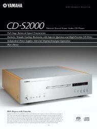
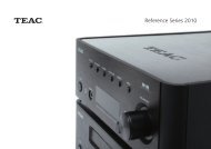
IDENTIFICATION OF CONTROLS<br />
FRONT PANEL<br />
1 2<br />
3 4 5 6 7 8 9 10<br />
ESPAÑOL<br />
ENGLISH<br />
FRANÇAIS<br />
11 12 13 14 15 16<br />
17<br />
18 19<br />
1 POWER BUTTON: Press this button or the HTRC 1 remote’s [ON]<br />
button to switch ON the T 785. The Standby LED indicator will turn from<br />
amber to blue and illuminate the VFD. Pressing the power button again<br />
turns the unit back to standby mode.<br />
The T 785 can also be switched ON from standby mode by pressing<br />
any of the front panel buttons. When both Main and Zones are ON,<br />
press and hold this button for more than five seconds to place them at<br />
standby mode.<br />
NOTES<br />
• The rear panel POWER switch must be in the ON position for the Power<br />
button to activate.<br />
• If Auto Trigger IN at Trigger Setup menu is assigned to “Main” or “All” and<br />
the TRIGGER switch is set to “AUTO” mode, the Power button in the front<br />
panel as well as the corresponding ON/OFF function keys in the HTRC 1<br />
remote control will be disabled effectively handing this function to an<br />
external controller. Switch TRIGGER to “OFF” to maintain normal power<br />
ON/OFF function procedures. (See section also about “TRIGGER SETUP”<br />
under the “SETUP MENU” discussions.)<br />
2 STANDBY LED: This indicator will light up amber when the T 785 is<br />
in standby state. When the T 785 main or zones are in the ON state,<br />
this indicator will illuminate blue. In the unlikely event that the T 785<br />
switches to protection state, then this indicator will illuminate red.<br />
When infrared command from the HTRC 1 is received, this indicator will<br />
also flash momentarily.<br />
3 INFO: Repeatedly toggle this button (press/hold first if in Tuner mode<br />
and then toggle) to display both at the Vacuum Fluorescent Display<br />
(VFD) and On-Screen Display (OSD) the following – Current Source,<br />
Volume level, Listening mode, Audio Source Format, and active Zones<br />
with their corresponding Source Inputs. While at Tuner mode, toggle<br />
this button to cycle through RDS name and RDS text.<br />
4 AM/FM/DB: Toggle this button to select either AM, FM, DAB (Europe<br />
version) or XM (North America version) tuner functions.<br />
5 TUNER MODE: In FM mode, this button will toggle between FM Stereo<br />
and FM mono. Select FM Mono (FM stereo and FM Mute icons at VFD<br />
are extinguished) for stations that have too much interference or are<br />
too weak. In DAB (European version only) or XM (North America version<br />
only) radio, this button enables the digital radio menus in conjunction<br />
with the Navigation button and Enter buttons.<br />
6 MEMORY: Press this button to store tuned AM, FM and digital radio<br />
stations to the T 785’s 40 preset-memory locations. One can store a mix<br />
of any AM, FM and digital radio stations to the 40 available presets.<br />
7 N<strong>AV</strong>IGATION and ENTER buttons: These buttons are used to<br />
navigate the T 785 OSD, Tune Forward [ ] and Tune Backward [ ],<br />
Preset Forward [ ] and Preset Reverse [ ] as well as navigation of<br />
DAB (European version), XM (North American version) tuner functions<br />
and iPod. The middle round button is designated as “ENTER” button; this<br />
is normally pressed to complete a selection, procedure, sequence or<br />
other applicable functions.<br />
8 VACUUM FLUORESCENT DISPLAY (VFD): Provide visual information<br />
on all important modes of the T 785 as well as the settings and<br />
functions for both Main and Zone locations.<br />
9 REMOTE SENSOR: Point the HTRC 1 remote control at the remote<br />
sensor and press the buttons. Do not expose the remote sensor of the<br />
T 785 to a strong light source such as direct sunlight or illumination. If<br />
you do so, you may not be able to operate the T 785 with the remote<br />
control.<br />
Distance: About 23ft (7m) from the front of the remote sensor.<br />
Angle: About 30o in each direction of the front of the remote sensor.<br />
10 VOLUME: Use this control to adjust the volume level of the main speakers.<br />
The default volume level is -20dB. The VOLUME knob is also used to<br />
increment/ decrement other adjustable parameters like Tone Controls.<br />
РУССКИЙ<br />
SVENSKA<br />
NEDERLANDS<br />
DEUTSCH<br />
ITALIANO
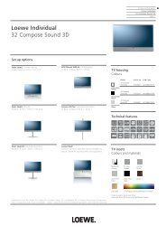
IDENTIFICATION OF CONTROLS<br />
FRONT PANEL<br />
ENGLISH FRANÇAIS ESPAÑOL ITALIANO DEUTSCH NEDERLANDS SVENSKA РУССКИЙ<br />
11 A SPEAKERS B: Press either speaker A or B or both to select the<br />
set of speakers you wish to listen to. Speaker A is the main set of 7<br />
multichannel and surround speakers. Speaker B is an auxiliary set<br />
for remote locations such as other rooms of your home. For Speaker<br />
B selection, all surround sound sources are downmixed to stereo.<br />
Combining Speaker A and Speaker B (SPEAKERS A + B) will also result to<br />
the source being downmixed to stereo.<br />
12 [ ] SOURCE [ ] : Press these buttons to toggle through the input<br />
selections – Source 1, Source 2, Source 3, Source 4, iPod, Source 7, Front<br />
Input, Media Player and Tuner. More Sources could be directly recalled<br />
through these buttons upon enabling them at the Setup Menu (See the<br />
section “SOURCE SETUP” at Setup Menu discussion).<br />
13 LISTENING MODE: Use to step through the T 785’s Listening mode as<br />
discussed in the section “LISTENING MODE”. Depending on the format of<br />
the currently selected input (digital or analog, stereo or multichannel),<br />
various listening modes are available.<br />
14 TONE CONTROLS: Press to adjust TREBLE control using the VOLUME<br />
knob over a + 10dB range. Press again to adjust BASS control and a<br />
third time for DIALOG control. See also section about “TONE CONTROLS”<br />
under “MAIN MENU” discussions.<br />
15 TONE DEFEAT: Tone Controls are enabled or disabled by pressing<br />
this button. Tone controls are bypassed at “Tone Defeat” while at “Tone<br />
Active”; the tone controls are enabled again. See also section about<br />
“TONE CONTROLS” under “MAIN MENU” discussions.<br />
16 FRONT INPUT/MP: Use this button to directly select Front Input and<br />
Media Player. Toggle button to switch between Front Input and Media<br />
Player input.<br />
17 PHONES: Accepts stereo headphone using a standard 1/4-inch stereo<br />
phone plug (use a suitable adapter for headphones equipped with a<br />
smaller plug). Plugging in headphones will automatically switch the<br />
T 785 to Stereo, Stereo Downmix or Analog Bypass modes.<br />
18 FRONT INPUT jacks: Use these convenience jacks for occasional<br />
sources such as a camcorder, tape player, video game console, any<br />
analog audio or optical digital audio and composite or S-Video video<br />
sources. If your source has a single audio out jack only or is marked<br />
“Mono output”, plug this into the T 785’s Front “R (Mono)” input. On<br />
the other hand, if your source has two output jacks indicative of stereo<br />
output, insert both jacks into the T 785’s corresponding Front “L” and “R<br />
(Mono)” input to achieve stereo output as well.<br />
19 MP/MIC input: Connect your MP3’s standard stereo phone jack to<br />
this input. This is the same input where Audyssey microphone jack is<br />
connected. (See also discussion about “AUDYSSEY AUTO CALIBRATION”.)
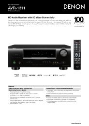
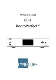
IDENTIFICATION OF CONTROLS<br />
REAR PANEL<br />
1 2 3 4 5 6 7 8 9 10<br />
11 12 13<br />
ESPAÑOL<br />
FRANÇAIS<br />
ENGLISH<br />
14<br />
16 17<br />
18 19<br />
20<br />
15<br />
ITALIANO<br />
ATTENTION!<br />
Please make sure that the T 785 is powered off or unplugged before making any connections. It is also advisable to power-down or unplug all associated<br />
components while making or breaking any signal or AC power connections.<br />
DEUTSCH<br />
1 DIGITAL AUDIO IN (OPTICAL 1-3, COAXIAL 1-3): Connect to the<br />
optical or coaxial S/PDIF-format digital output of sources such as CD or<br />
DVD players, HDTV or satellite tuners and other components. Coaxial<br />
and Optical digital input association is configurable via the Setup Menu.<br />
DIGITAL AUDIO OUT (OPTICAL, COAXIAL): Connect the optical or<br />
coaxial digital OUT port to the corresponding S/PDIF digital input of a<br />
compatible device such as CD recorders, receivers, computer soundcard<br />
or other digital processors.<br />
2 FM, AM ANTENNA INPUT: The supplied wire “dipole” FM antenna will<br />
connect to the FM connector using the supplied “balun” adapter. It will<br />
usually work best when mounted on a vertical surface such as a wall,<br />
with arms fully outstretched forming a horizontal “T” perpendicular to<br />
the origin point of the signal.<br />
Connect the supplied AM loop antenna to these terminals. If an external<br />
AM antenna is used, make connections to the AM and GND terminals<br />
in accordance with the instructions supplied with the antenna. See also<br />
section about “LISTENING TO RADIO”.<br />
3 COMPONENT VIDEO 1-3 IN, COMPONENT VIDEO OUT: Connect<br />
the Component Video IN 1-3 inputs to Component Video outputs<br />
from compatible source components, typically a DVD player and<br />
terrestrial or satellite HDTV tuner. Connect Component Video OUT to<br />
the Component Video input of a compatible video monitor/TV. Be<br />
sure to observe consistency in connecting the Y/Pb/Pr jacks to the<br />
corresponding sources/inputs. The routing of the component video<br />
inputs is fully configurable via the Setup Menu.<br />
The T 785’s component video inputs and outputs are fully wideband<br />
and compatible with allowable HDTV formats.<br />
4 MP DOCK: The T 785 is equipped with a data port in the rear panel<br />
where an optional “NAD IPD 1 Dock with iPod” (NAD IPD 1) can be<br />
plugged in. Connect the “MP DOCK (DATA PORT)” jack of the T 785 to<br />
the corresponding “DATA PORT” socket of the optional NAD IPD 1.<br />
NEDERLANDS<br />
SVENSKA<br />
РУССКИЙ
IDENTIFICATION OF CONTROLS<br />
REAR PANEL<br />
ENGLISH FRANÇAIS ESPAÑOL ITALIANO DEUTSCH NEDERLANDS SVENSKA РУССКИЙ<br />
5 AUDIO 3 OUT/VIDEO 3 OUT, AUDIO 4 OUT/VIDEO 4 OUT: Connect<br />
the T 785’s AUDIO 3 OUT/VIDEO 3 OUT or AUDIO 4 OUT/VIDEO 4 OUT<br />
jacks to the analog audio/video input of a recording component<br />
such as a cassette deck, DVD recorder or to an outboard audio/video<br />
processor. Connect the T 785’s AUDIO 3 IN/VIDEO 3 IN or AUDIO 4<br />
IN/VIDEO 4 IN jacks to the component’s corresponding output.<br />
The signal present at these T 785 AUDIO/VIDEO OUT jacks is determined<br />
by the source last selected via the front panel Source keys or the<br />
HTRC 1’s input select keys with the exception of Source 3 or Source<br />
4. There will be no output when Source 3 (Audio 3 IN/Video 3 IN)<br />
or Source 4 (Audio 4 IN/Video 4 in) is the selected source input.<br />
This prevents feedback through the recording component thereby<br />
preventing possible damage to your speakers.<br />
When configured, AUDIO 3 OUT/VIDEO 3 OUT and AUDIO 4 OUT/VIDEO<br />
4 OUT are the same assigned ports for Zone 3 and Zone 4 respectively.<br />
See also Zone output description below.<br />
6 MONITOR (S-VIDEO, VIDEO): Connect to video input of the monitor/<br />
television using quality dual-RCA and/or S-Video cables designed for<br />
video signals. In general, the S-Video connection is superior and should<br />
be used if your TV/monitor provides the corresponding input.<br />
7 AUDIO 1 IN/VIDEO 1 IN, AUDIO 2 IN/VIDEO 2 IN, AUDIO 3<br />
IN/VIDEO 3 IN, AUDIO 4 IN/VIDEO 4 IN, AUDIO 5 IN/VIDEO 5<br />
IN, AUDIO 6 IN: These comprise the T 785’s principal input. Connect<br />
S-Video, composite video, and analog stereo audio from source<br />
components such as DVD players and HDTV/satellite tuners.<br />
AUDIO 3 IN/VIDEO 3 IN, AUDIO 4 IN/VIDEO 4 IN may be used with<br />
recording components such as videocassette or DVD-recorders by<br />
connecting these components’ record-inputs to the corresponding<br />
T 785 AUDIO 3 IN/VIDEO 3 IN or AUDIO 4 IN/VIDEO 4 IN jacks. AUDIO<br />
3 IN/VIDEO 3 IN or AUDIO 4 IN/VIDEO 4 IN may freely be used for<br />
play-only components, in which case their OUT jacks would remain<br />
unconnected. Refer also to “AUDIO 3 OUT/VIDEO 3 OUT, AUDIO 4 OUT/<br />
VIDEO 4 OUT” discussion above.<br />
AUDIO 6 IN is advisable to connect to dedicated analog output from<br />
line-level audio sources like a CD player or Stereo tuner.<br />
8 7.1 CH INPUT: Connect to the corresponding analog audio outputs of a<br />
multichannel source component such as a DVD-Audio or multichannel-<br />
SACD player or external multichannel decoder (disc copy protected<br />
formats only allow analog signal transfer). Typically, these sources will<br />
produce 5.1-channel output, in which case the <strong>Surround</strong> Back jacks are left<br />
unconnected. The signals present at these jacks may be heard by selecting<br />
Source 7 (7.1 Channel Input is defaulted to this Source).<br />
There is no bass-management or other processing (other than mastervolume<br />
control) available to this 7.1 Channel Input. While the multichannel<br />
audio outputs of a DVD-Video player can be connected to<br />
these jacks, using the T 785’s own Dolby Digital and DTS decoding and<br />
digital-analog converters via a digital connection will usually produce<br />
superior results.<br />
9 XM MODULE INPUT (North America version only): Connect XM<br />
radio cable to this socket. Follow the instructions that came with your<br />
XM radio. With XM radio, there are more than 100 channels of music,<br />
news, sports, comedy, talk and entertainment. You will find that the<br />
coverage is continent wide. The music quality is digital with many<br />
commercial-free music channels.<br />
NOTES<br />
Questions? Visit www.xmradio.com<br />
Listeners can subscribe by visiting XM on the Web at www.xmradio.com<br />
or by calling (at the time of printing this manual) XM’s Listener Care at<br />
(800) 853 9696. Be ready with your Radio ID that can be found on the<br />
radio by selecting Channel 0.<br />
DAB MODULE INPUT (Europe version only): Plug-in the other end<br />
of the Mini-Din connector from the NAD DAB Adaptor DB 1 module<br />
output port into this socket. The T 785 is compatible only with NAD<br />
DAB Adaptor DB 1 so check with your NAD dealer for this module’s<br />
availability. With DAB, you can receive CD-like quality programs without<br />
any annoying interference and signal distortion.<br />
10 RS-232: Connect this interface via RS-232 serial cable (not supplied) to any<br />
Windows® compatible PC to allow remote control of the T 785 through<br />
NAD’s proprietary PC software or other compatible external controllers.<br />
NAD is a certified partner of AMX and Crestron and fully supports these<br />
external devices. See your NAD audio specialist for more information.<br />
11 SOFT CLIPPING: Enables NAD’s proprietary Soft Clipping circuitry on<br />
all channels. At [ON] position, Soft Clipping gently limits the output of<br />
the T 785 to minimize audible distortion should the A/V <strong>Receiver</strong> be<br />
over-driven. Soft Clipping may simply be left ON at all times to reduce<br />
the likelihood of audible distortion from excessive volume settings.<br />
However, for critical listening and to preserve optimum dynamics, you<br />
may wish to defeat it by setting this switch OFF.<br />
12 +12 V TRIGGER OUT: There are three configurable +12V TRIGGER<br />
OUTPUT. Use a 3.5mm mini-jack connector to pass +12 volts at a<br />
maximum current of 50 milliamps to auxiliary equipment such as a<br />
multichannel amplifier or subwoofer. The centre conductor (hot) of the<br />
3.5mm jack is the control signal. The outside conductor (shield) is the<br />
ground return-path.<br />
TRIGGER IN accepts 12V Trigger output of compatible components such<br />
as power controllers and home automation devices.<br />
TRIGGER OFF/AUTO. When at AUTO position, the T 785 selects the 12V<br />
Trigger Input to turn ON (if so assigned at the “Trigger Setup” menu) and<br />
at the same time disables the HTRC 1 and ON/OFF function of the front<br />
panel. When set to [OFF] position, the trigger input is disabled.<br />
See discussion on “TRIGGER SETUP” at the “SETUP MENU” literature for<br />
guidelines on how to configure TRIGGER IN/OUT.<br />
WARNING<br />
If Auto Trigger IN at Trigger Setup menu is assigned to “Main” or “All” and<br />
the TRIGGER switch is set to “AUTO” mode, the Power button in the front<br />
panel as well as the corresponding ON/OFF function keys in the HTRC 1<br />
remote control will be disabled effectively handing this function to an<br />
external controller. Switch TRIGGER to”OFF” to maintain normal power<br />
ON/OFF function procedures.<br />
10
IDENTIFICATION OF CONTROLS<br />
REAR PANEL<br />
13 IR IN/OUT: These mini-jacks accept and output remote-controlled<br />
codes in electrical format, using industry-standard protocols, for use<br />
with “IR-repeater” and multi-room systems and related technologies.<br />
IR IN : This input is connected to the output of an IR (infrared) repeater<br />
(Xantech or similar) or the IR output of another component to allow<br />
control of the T 785 from a remote location.<br />
IR OUT 2 : When connected to the IR IN of ancillary equipment, direct<br />
the ancillary equipment’s own remote control to the T 785’s infrared<br />
receiver to command or control the linked unit.<br />
IR IN and IR OUT 3 : Connect the T 785’s IR IN to the IR OUT of ancillary<br />
equipment. Connect also the T 785’s IR OUT 3 to another equipment<br />
with IR IN feature. With this setup, the T 785 acts as an “IR-repeater”<br />
allowing the equipment connected to the T 785’ s IR IN control or<br />
command of the other equipment linked to the T 785’s IR OUT 3.<br />
IR OUT 1 : In conjunction with IR IN, IR OUT 1 can be used as an “IRrepeater”<br />
just like the IR OUT 3 as described above. It can also stand<br />
alone as an IR OUT similar to that of IR OUT 2 function.<br />
All NAD products with IR IN/IR OUT features are fully compatible with<br />
the T 785. For non-NAD models, please check with your other product’s<br />
service specialists as to their compatibility to the T 785’s IR features.<br />
14 HDMI (HDMI 1-4, HDMI MONITOR OUT): Connect HDMI inputs to<br />
the HDMI OUT connectors of source components such as DVD player or<br />
HDTV satellite/cable box. Connect the HDMI Monitor OUT to a HDTV or<br />
projector with HDMI input.<br />
WARNING<br />
Before connecting and disconnecting any HDMI cables, both the T 785<br />
and the ancillary source must be powered OFF and unplugged from the<br />
AC outlet. Failure to observe this practice may cause permanent damage<br />
to all equipment connected via HDMI sockets.<br />
15 ZONE 2, ZONE 3, ZONE 4: Sends zone selected audio and video<br />
output sources to the corresponding audio and video input of another<br />
separate zone. Use high quality patch cables to reduce noise pickup<br />
over long distance runs. For a better understanding of zone settings,<br />
study below the section on “ZONE CONTROLS” of the “MAIN MENU”<br />
discussion as well as the item on “ZONE SETUP” under the “SETUP MENU”<br />
literatures.<br />
NOTE<br />
The ZR 4 remote control will only control Zone 2 applications. Zone 3<br />
and Zone 4 could be configured and managed at the appropriate Zone<br />
OSD menu using the front panel navigations buttons as well as the<br />
corresponding keys on the HTRC 1 remote control.<br />
16 AUDIO PRE-OUT: The Audio PRE- OUT makes it possible to use the<br />
T 785 as a pre-amplifier to external power amplifiers for some or all<br />
channels. Connect FRONT L, FRONT R, SURR R, SURR L, SURR-BL,<br />
SURR-BR and CENTER to the respective channel input of a power<br />
amplifier or an amplifier driving the corresponding applicable speakers.<br />
Unlike the full range channels, there is no power amplifier built-into the<br />
T 785 for a subwoofer. Connect the SUBW 1 or SUBW 2 output or both<br />
to powered (“active”) subwoofers or to power amplifier channels driving<br />
a passive system.<br />
17 SPEAKERS A, SPEAKERS B : Connect the respective SPEAKER A’s<br />
FRONT L, FRONT R, SURR R, SURR L, SURR-BL, SURR-BR and<br />
CENTER channels to their corresponding loudspeakers. Make sure<br />
the “+” (red) terminal and “-“(black) terminal are connected to the<br />
corresponding “+” and “-“terminals of the loudspeaker. Use extra care to<br />
ensure that no stray wires or strands cross between posts or terminals at<br />
either end.<br />
Connect left and right channels of Speakers B to the corresponding<br />
remote loudspeakers. When Speakers B is activated, the output is<br />
converted to “Stereo Downmix” as indicated in the VFD. Combining<br />
Speaker A and Speaker B (SPEAKERS A + B) will also result to the source<br />
being downmixed to stereo.<br />
The T 785 is designed to produce optimum sound quality when<br />
connected to speakers with impedances within its operating range.<br />
Please make sure that all the speakers are rated 4 ohms minimum per<br />
speaker.<br />
NOTE<br />
Use stranded wire of at least 16 gauge (AWG). Connections to the T 785<br />
can be made with banana plugs (US model only) or by using bare wire<br />
or pins. Use the transverse hole through the post for bare-wire or pin<br />
connections. By loosening the terminal’s plastic nut, make a clean, neat<br />
connection and re-tighten carefully. To minimize the danger of shortcircuit,<br />
ensure that only 1/2-inch of exposed wire or pin is employed<br />
when connecting.<br />
18 AC POWER INLET: Connect to the supplied IEC-standard removable<br />
AC power cord or a compatible cord.<br />
19 SWITCHED AC OUTLET: This convenience outlet can supply switched<br />
power to another component or accessory. It is powered ON and OFF<br />
by the front panel POWER SWITCH or by the HTRC 1’s ON and OFF keys.<br />
The total draw of all devices connected to this outlet must not exceed<br />
120 watts for North America version and 115W for European version.<br />
20 POWER: The POWER switch supplies the master AC mains power for<br />
the T 785. When this switch is at ON position, the T 785 is in standby<br />
mode as shown by the amber status condition of the standby LED. If<br />
you intend not to use the T 785 for long periods of time (such as when<br />
on vacation), switch the POWER switch to the OFF position. When the<br />
POWER switch is at OFF position, the front panel power button, HTRC 1<br />
remote control or ZR 4 cannot activate the T 785.<br />
SVENSKA<br />
NEDERLANDS<br />
DEUTSCH<br />
ITALIANO<br />
ESPAÑOL<br />
FRANÇAIS<br />
ENGLISH<br />
NOTE<br />
Never connect both the external amplifier and T 785’s speaker outputs to<br />
the same set of speakers.<br />
РУССКИЙ<br />
11
OPERATION<br />
USING THE T 785 – MAIN MENU<br />
ENGLISH FRANÇAIS ESPAÑOL ITALIANO DEUTSCH NEDERLANDS SVENSKA РУССКИЙ<br />
ABOUT THE ON-SCREEN DISPLAY (OSD)<br />
The T 785 employs a simple, self-explanatory system of on-screen display “menus” that will appear<br />
on the connected video monitor/TV. These are required during the setup process (and are useful<br />
in day-to-day operation), so be sure to connect the monitor/TV before proceeding with setup.<br />
DISPLAY THE OSD<br />
Press either [ ] or [ENTER] buttons of the HTRC 1 remote control or front panel to display the T 785’s Main<br />
Menu on your video monitor/TV. If the OSD does not appear, check your MONITOR OUT connections.<br />
N<strong>AV</strong>IGATING THE OSD AND MAKING CHANGES<br />
To navigate through the OSD menu options, please do the following using the HTRC 1 or<br />
corresponding front panel buttons:<br />
1 Press [ ] or [ENTER] to select a menu item. Use [ ] keys or in some cases, [ENTER] to move up or<br />
down the Menu selections. Repeatedly press [ ] to advance or go further into sub-menus of a desired<br />
menu item.<br />
2 Use [ ] keys to set or change the parameter value (setting) of a menu item.<br />
3 Press [ ] to save the settings or changes done on the current menu or sub‐menu. Pressing [ ]<br />
will also return the user to the previous menu or exit from a particular menu.<br />
MAIN MENU<br />
The Main Menu contains the menu options for “Listening Mode”, “DSP Options”, “Tone Controls”, “Zone<br />
Controls” and access to “Setup Menu”.<br />
To navigate through these Main Menu options and their sub-menu selections, please refer to and<br />
follow the directions stated in the sections “DISPLAY THE OSD” and “N<strong>AV</strong>IGATING THE OSD AND<br />
MAKING CHANGES”.<br />
NOTE<br />
The individual configurations set forth at “Listening Mode”, “DSP Options” and “Tone Controls”<br />
are carried over whenever they are enabled during A/V Preset setting. Please see the section “A/V<br />
PRESETS” for reference.<br />
LISTENING MODE<br />
The T 785 offers nine distinct listening modes, tailored for different types of recording or program<br />
material. With a two-channel (Stereo) source, the following listening modes can be selected:<br />
STEREO<br />
All output is directed to the front left/right channels. Low frequencies are directed to the subwoofer<br />
if one is present in the Speaker settings. Select “Stereo” when you wish to listen to a stereo (or<br />
monaural) production, such as music CD or FM broadcast, without surround enhancement. Stereo<br />
recordings whether in PCM/digital or analog form and whether surround-encoded or not encoded,<br />
are reproduced as recorded. Multi-channel digital recordings (Dolby Digital and DTS) are reproduced in<br />
“Stereo Downmix” mode via the front left/right channels only as Lt/Rt (left/right-total) signals.<br />
PRO LOGIC<br />
Two-channel recordings, whether stereo or surround-encoded, are reproduced with Dolby Pro<br />
Logic surround processing, yielding output to front left/right, center and discrete left/right surround<br />
channels (assuming these are present in the current “Speaker Configuration”). The surround channel is<br />
monophonic, but it is reproduced in both surround speakers.<br />
12
OPERATION<br />
USING THE T 785 – MAIN MENU<br />
PRO LOGIC PLII<br />
Dolby Pro Logic II is a more recent evolution of the original Dolby Pro Logic surround processing that<br />
yields more stable imaging and full bandwidth sound to the rear channels in Movie mode, offering<br />
sound that is more similar to Dolby Digital decoding.<br />
ENGLISH<br />
PRO LOGIC IIx<br />
Dolby Pro Logic IIx processes both stereo and 5.1 signals into a 6.1 or 7.1 channel output. At Dolby<br />
Pro Logic IIx, you can choose PLIIx Movie or PLIIx Music modes to tailor your listening experience<br />
to the source material. Dolby Pro Logic IIx surround processing yields more stable imaging and<br />
full bandwidth sound to the rear channels in Movie mode offering sound that is more similar to<br />
Dolby Digital decoding. For two channel signals, Dolby Pro Logic IIx Music mode also features three<br />
additional user controls - Dimension, Center Width, and Panorama. See also section about “ADJUSTING<br />
LISTENING MODES” below.<br />
The following chart shows the channels available assuming they are enabled in the “Speaker<br />
Configuration” menu;<br />
FRANÇAIS<br />
Listening Mode<br />
Two-Channel Sources<br />
Dolby Pro Logic IIx Music<br />
Dolby Pro Logic IIx Movie<br />
Active Decoded Output Channels<br />
6.1 Speaker System 7.1 Speaker System<br />
Front (left & right), Center, <strong>Surround</strong><br />
(left & right), Back <strong>Surround</strong>,<br />
Subwoofer<br />
Front (left & right), Center, <strong>Surround</strong><br />
(left & right) and Back <strong>Surround</strong> (left<br />
and right) and subwoofer<br />
ESPAÑOL<br />
NEO:6<br />
Two-channel recordings, whether stereo or surround-encoded, are reproduced with Neo:6 surround<br />
with output to front left/right, center and discrete left/right surround channels plus subwoofer<br />
(assuming these are present in the current “Speaker Configuration”). The T 785 provides two DTS Neo:6<br />
variations - CINEMA and MUSIC. See also section about “ADJUSTING LISTENING MODES” below.<br />
EARS<br />
Two-channel recordings, whether stereo or surround-encoded, are reproduced with proprietary NAD<br />
surround processing with signals output to the front left/right, center and discrete left/right surround<br />
channels, plus subwoofer (assuming these are present in the current “Speaker Configuration”). EARS<br />
does not employ the surround back speakers (if any).<br />
EARS extracts the natural ambience present in nearly all well-produced stereo recordings. It does not<br />
synthesize any ambience or other sonic elements and thus remains truer to the sound of the original<br />
musical performance than most other music-surround options.<br />
Select EARS for listening to stereo music recordings and broadcasts. EARS produces a subtle but highly<br />
natural and believable ambience from nearly all “natural-acoustic” stereo recordings. Typically, these<br />
include classical, jazz, and folk genres as well as numerous examples from others. Its virtues include<br />
realistic, stable “front-stage” sonic imaging and spacious but unexaggerated ambient “virtual acoustics”<br />
that remain faithful to the original recording.<br />
ENHANCED STEREO<br />
All recordings reproduced in stereo via the maximum speaker complement configured in the current<br />
“Speaker Configuration”. Enhanced stereo can be useful for maximum volume from all channels or for<br />
multi-speaker background music (cocktail party) listening. For this mode, Front, Center, <strong>Surround</strong> and<br />
Back speakers can be turned ON/OFF as desired.<br />
ANALOG BYPASS<br />
All analog signals remain in the analog domain without analog-to-digital conversions. At Analog<br />
Bypass, the DSP circuitry is bypassed but full tone control functions remain. “Bass management” or<br />
“Speaker Setup” settingare also not in effect as these are DSP functions.<br />
РУССКИЙ<br />
SVENSKA<br />
NEDERLANDS<br />
DEUTSCH<br />
ITALIANO<br />
13
OPERATION<br />
USING THE T 785 – MAIN MENU<br />
ENGLISH FRANÇAIS ESPAÑOL ITALIANO DEUTSCH NEDERLANDS SVENSKA РУССКИЙ<br />
ADJUSTING LISTENING MODES<br />
Several of the T 785’s listening modes have one or more selectable variations and adjustable<br />
parameters that you can modify to suit your personal preferences. At Listening Mode menu, use a<br />
combination of the [ENTER] and [ ] keys to navigate and effect desired settings.<br />
NOTE<br />
Listening Mode parameter changes are maintained when you change listening modes. You may<br />
also save a modified Listening Mode for easy recall by saving it to a Preset (See “A/V PRESETS” below<br />
under Setup Menu discussions).<br />
PRO LOGIC IIx<br />
PLIIx MOVIE is optimized for film soundtracks.<br />
PLIIx MUSIC for music recordings.<br />
CENTER WIDTH (0 to 7): Modifies the “hard-centeredness” of the center image, by gradually mixing<br />
mono center content to the Front left/right speakers as well. A setting of 0 retains the centerchannel-only<br />
default while a setting of 7 yields a fully phantom center channel.<br />
DIMENSION (-7 to +7): Adjusts front-rear emphasis of the surround effect independently from the<br />
relative channel levels.<br />
PANORAMA (On/Off ): Adds a “wrap around” effect by extending some stereo content into the<br />
surround channels.<br />
NOTE<br />
Pro Logic IIx mode will decode as Pro Logic II mode when the BACK surround speakers are set to<br />
“Off” from “Speaker Configuration” menu. See also section about “SPEAKER CONFIGURATION”<br />
under “SPEAKER SETUP” of the Setup Menu.<br />
NEO:6<br />
Neo:6 Cinema is optimized for film soundtracks.<br />
Neo:6 Music for music recordings.<br />
CENTER GAIN (0 to 0.5): Adjust for better center image in relation to the surround sound channels.<br />
DSP OPTIONS<br />
DSP Options has the feature “Lip Sync Delay” whose function is to match any delay that may occur in<br />
the picture relative to the audio.<br />
By varying “Lip Sync Delay” from 0ms to 120ms, one can delay the audio output in order to synchronize<br />
it with the video image.<br />
TONE CONTROLS<br />
The T 785 has three Tone Control levels – Treble, Bass and Center Dialog. Bass and Treble controls only<br />
affect the low bass and high treble leaving the critical midrange frequencies free of coloration. The<br />
Center Dialog control boosts the “presence” of the midrange region improving intelligibility of speech.<br />
These controls allow one to tweak on-the-fly, the frequency response of the source during playback.<br />
The control setting could be adjusted by navigating through the Tone Controls OSD menu via a<br />
combination of [ENTER] and [ ] keys. The same can be managed directly by pressing the front<br />
panel’s “TONE CONTROLS” button and then rotating the Volume knob to select desired setting.<br />
Maximum and minimum values for all three Tone Control levels are +/- 10 dB.<br />
“Tone Defeat” gives one the choice of varying or completely bypassing the tone control section of the<br />
T 785. If “Off” (Tone Active in the VFD) is selected, the Tone Control circuits are active.<br />
Select “On” to bypass the Tone Controls effectively defeating the effect of the tone control circuits.<br />
14
OPERATION<br />
USING THE T 785 – MAIN MENU<br />
ZONE CONTROLS<br />
Depending on the settings made at the separate “Zone Setup” menu under the “Setup Menu” section<br />
discussion, the applicable Zone can be configured and managed via this “Zone Controls” window.<br />
Select “On” to activate the applicable Zone. When activated, the Source input for the particular Zone<br />
can be allocated by selecting through the following inputs – All enabled Sources, Front Input, Media<br />
Player, Tuner and Local.<br />
Select “Local” as your selected Zone’s Source input if you wish to enjoy the same source as the main<br />
Zone and allow simultaneous listening, but with full separate volume levels.<br />
If a Zone is set to “Off”, it is deactivated or powered off.<br />
“Volume” refers to the adjustable secondary Zone Volume level that can be increased or decreased<br />
using the [ ] buttons of the HTRC 1 or front panel’s.<br />
When a Zone is activated, a corresponding Zone number is illuminated at the VFD. Zone 2 is always<br />
available to be configured at “Zone Controls” menu. For Zone 3 and Zone 4 to become available at the<br />
“Zone Controls” window, their corresponding “Mode” in the “Zone Setup” menu under the “Setup Menu”<br />
section should be set to “Zone (Audio Only)”.<br />
NOTE<br />
The ZR 4 remote control will only control Zone 2 applications. Zone 3 and Zone 4 could be<br />
configured and managed at the appropriate Zone OSD menu using the front panel navigations<br />
buttons as well as the corresponding keys on the HTRC 1 remote control.<br />
РУССКИЙ<br />
SVENSKA<br />
ENGLISH<br />
FRANÇAIS<br />
ESPAÑOL<br />
ITALIANO<br />
NEDERLANDS<br />
DEUTSCH<br />
15
OPERATION<br />
USING THE T 785 –SETUP MENU<br />
ENGLISH FRANÇAIS ESPAÑOL ITALIANO DEUTSCH NEDERLANDS SVENSKA РУССКИЙ<br />
SETUP MENU<br />
The Setup Menu allows one to customize the operation of the T 785 to the ancillary equipment used<br />
in one’s specific <strong>AV</strong> system. Unless your system exactly matches the factory defaults as shown in the<br />
accompanying Quick Start Guide, you will need to use the setup menu to configure the inputs of the T 785.<br />
At Setup Menu, the following are configurable – Source Setup, Speaker Setup, Zone Setup, Amplifier<br />
Setup, Trigger Setup, Listening Mode Setup, Display Setup and A/V Presets.<br />
To access and navigate through Setup Menu and its sub-menu selections, please refer to and follow<br />
the directions stated in the sections “DISPLAY THE OSD” and “N<strong>AV</strong>IGATING THE OSD AND MAKING<br />
CHANGES”.<br />
SOURCE SETUP<br />
From Source Setup menu, pressing [ ] will direct you to the Source Setup menu wherein you could<br />
adjust allocate or change the settings of the following – Source Setup (Normal View), Source Setup<br />
(Table View) and iPod Setup.<br />
SOURCE SETUP (NORMAL VIEW)<br />
The Source Setup (Normal View) makes it possible to set, allocate or change the following settings.<br />
SOURCE<br />
The T 785 is equipped with ten configurable Sources. The settings for each Source are dependent on<br />
the configurations set forth in the parameters for that particular Source window.<br />
To change or toggle through the Sources, scroll to “Source”, press the buttons [<br />
[ ] to move up or down the Source selections.<br />
] and then ENTER or<br />
NOTE<br />
Source 5 is defaulted to iPod. For Source 5 to be changed and allocated for other inputs, go to “iPod<br />
Setup” menu under the “Source Setup” menu. At iPod Setup menu, set “Enabled” to “No” – you can<br />
now assign Source 5 to other inputs or settings as desired.<br />
ENABLED<br />
One can enable/disable a Source via this option. This is particularly useful if only few Sources are used<br />
and one directly selects the Source from the front panel, bypassing unused sources.<br />
To enable or disable a particular Source, scroll to “Enabled” and press [<br />
] keys to select “Yes” or “No”.<br />
NAME<br />
A new Name maybe assigned to a Source label. For example, if your DVD player is attached to “Source<br />
1”, it is possible to rename “Source 1” to “DVD Player”.<br />
In order to rename the Source label, scroll to “Name” and press [ ] to go the character.<br />
Then, press [ ] to pick through the alphanumeric selections.<br />
Press [ ] to move to the next character and at the same time save the changes done on the<br />
current character. The name can be as long as twelve characters.<br />
The new Name will be shown in the VFD as well as on the OSD.<br />
16
OPERATION<br />
USING THE T 785 –Setup MENU<br />
ANALOG AUDIO<br />
The T 785 has nine analog audio inputs including 7.1 input. These analog inputs - Audio 1, Audio 2,<br />
Audio 3, Audio 4, Audio 5, Audio 6, Audio Front, Audio MP and 7.1 Input can be variably assigned to<br />
each Source.<br />
Scroll to “Analog Audio” and then press [ ] to select and assign an analog audio input to the particular<br />
Source. There are three choices – Audio, 7.1 Input or Off.<br />
When “Audio” is chosen, press [ ] and then [ ] keys to select and assign the desired audio input<br />
– 1 to 6, Front and MP.<br />
Select “7.1 Input” to choose the audio signal fed to “7.1 Channel Input”. If “Off” is selected, no incoming<br />
analog audio signal is selected by the particular Source.<br />
NOTE<br />
An incoming digital signal present at the assigned digital input will always take precedence over the<br />
assigned analog audio input, even if both are present. To maintain the analog audio input for the<br />
particular Source, select “Off” at the “Digital Audio” setting of the same ”Source” menu.<br />
GAIN<br />
Gain adjustment allows all sources to play back at the same volume so you don’t need to adjust the<br />
volume every time a new source is selected. It is generally preferable to reduce the level of the loudest<br />
source rather than making louder the softer sources.<br />
ENGLISH<br />
FRANÇAIS<br />
ESPAÑOL<br />
Scroll to “Gain”, press [ ] and then [ ] to step through the desired level from -12dB to 12dB.<br />
DIGITAL AUDIO<br />
To take advantage of the T 785’s high performance surround and digital audio circuitry, it is advisable<br />
that its Digital Audio inputs are selected.<br />
There are three types of Digital Audio input for the T 785. These are HDMI, Optical and Coaxial digital inputs.<br />
A fourth option is “Off” whereby no incoming digital audio signal is selected by the particular Source.<br />
The desired digital audio input for a particular Source can be selected by scrolling to “Digital Audio”, press<br />
[ ] and then [ ] to step through the desired digital input source. After finalizing which type of Digital<br />
Audio input is desired, press [ ] and then [ ] again to select the specific Digital Audio input.<br />
There are eleven Digital Audio inputs selectable for the T 785. They are the following<br />
HDMI HDMI 1, HDMI 2, HDMI 3, HDMI 4<br />
Optical Optical 1, Optical 2, Optical 3, Optical Front<br />
Coaxial Coaxial 1, Coaxial 2, Coaxial 3<br />
NOTE<br />
An incoming digital signal present at the assigned digital input will always take precedence over the<br />
assigned analog audio input, even if both are present. To maintain the analog audio input for the<br />
particular Source, select “Off” at the “Digital Audio” setting of the same “Source” menu.<br />
VIDEO<br />
There are four types of video input a particular Source could be assigned. These are HDMI, Component,<br />
S-Video and Video inputs. A fifth option is “Off” wherein the particular Source is prompted not to select<br />
any Video input.<br />
Navigating through the Video input selections involve a combination of pressing [ ] and then [ ]<br />
to step through the selections. The following are the assignable Video inputs<br />
HDMI HDMI 1, HDMI 2, HDMI 3, HDMI 4<br />
Component Video Component 1, Component 2, Component 3<br />
S-Video S-Video 1, S-Video 2, S-Video 3, S-Video 4, S-Video 5, S-Video Front<br />
Video Video 1, Video 2, Video 3, Video 4, Video 5, Video Front<br />
NOTE<br />
An audio input and video input should always be associated to a selected Source setting to ensure audio and video<br />
output. If “Off” is selected for any of the Analog Audio, Video or Digital Audio settings, there will be no corresponding<br />
audio or video for the associated Source. For example, if the selected Video setting for a particular Source is HDMI 1<br />
and both Digital and Analog Audio are set to “Off”, only video output will be available but no audio. Ideally, when<br />
the selected Video input is HDMI 1, it follows that the Digital Audio input is set to HDMI 1 or any of the digital inputs.<br />
Refer also to the QUICK START section under the INTRODUCTION – GETTING STARTED page.<br />
РУССКИЙ<br />
SVENSKA<br />
NEDERLANDS<br />
DEUTSCH<br />
ITALIANO<br />
17
OPERATION<br />
USING THE T 785 –Setup MENU<br />
ENGLISH FRANÇAIS ESPAÑOL ITALIANO DEUTSCH NEDERLANDS SVENSKA РУССКИЙ<br />
ABOUT VIDEO FORMATS<br />
For many years, there was only one type of video format used. Composite video signals include the<br />
Luminance (black & White) and Chroma (color) signals combined on one wire. S-Video uses separate<br />
wires in a single cable for Luminance and Chroma signals. Component Video goes a step further<br />
with separate cables for Luminance and the two elements of Chroma. For NTSC (America, Japan)<br />
as well as PAL signals(Europe, Asia) these are labeled Y, Cr, Cb. Television studios use the Component<br />
Video format to keep these signals separate in order to maintain the best quality. As consumer video<br />
equipment has improved this higher quality format has been included.<br />
VIDEO FORMAT CONVERSION<br />
The T 785 is equipped with a Video Format Converter. This allows for a simplified video connection<br />
between the T 785 and your TV Monitor when using multiple video formats such as Composite (CVBS),<br />
S-Video, and Component (YUV). This format change is accomplished by encoding the analog video<br />
signal into a digital signal using a very high quality digital encoder to maintain the best possible<br />
picture quality. Once in a digital format, it can be decoded into any of the three standard analog video<br />
formats. These analog outputs are also up-converted to HDMI output. Video output availability will<br />
depend on the resolution capability of your TV/Monitor.<br />
It is suggested that you select the highest quality video format available on your TV Monitor and utilize this<br />
for your Monitor OUT connection from the T 785 to the TV Monitor. In most cases this will be Component<br />
Video or HDMI (where possible), but on some older TV’s S-Video may be the best quality connection.<br />
A/V PRESET<br />
A particular Source can be assigned a stored Preset. The parameters set up in the selected Preset<br />
number will be adopted into the particular Source it is assigned (Please refer to the separate section on<br />
“A/V PRESETS” for further understanding of Preset settings).<br />
Scrolling to “A/V Preset” and by pressing [ ] and then [ ] keys, a Source could be assigned a<br />
Preset number ranging from Preset 1 to 5.<br />
If it is desired not to assign the particular Source a Preset setting, select “None”.<br />
TRIGGER OUT<br />
The Trigger Out for a particular Source is dependent on the configurations done in a separate menu on Trigger<br />
Setup (See “TRIGGER SETUP” below). If all three available Trigger outputs are assigned to “Source Setup” in the<br />
separate “Trigger Setup” window, a particular Source can have the following Trigger Out combinations<br />
Trigger Out 1 2 1 + 2 3 1 + 3 2 + 3 1+2+ 3<br />
These combinations are dependent on the assignment of “Source Setup” for “Trigger 1 Out, Trigger 2<br />
Out or Trigger 3 Out” at the Trigger Setup menu.<br />
Another option is “Off” whereby the particular Source is not assigned any Trigger Out.<br />
For “Trigger Out” to become enabled and assignable at “Source Setup (Normal View)” menu, make sure<br />
to carry out or note the following beforehand<br />
• In the separate “Trigger Setup” menu, assign “Trigger 1 Out, Trigger 2 Out or Trigger 3 Out” to<br />
“Source Setup”.<br />
• “Trigger Out” will not appear as an option at the Source Setup (Normal View) menu if at the<br />
separate “Trigger Setup” menu, “Trigger 1 Out, Trigger 2 Out or Trigger 3 Out” are all assigned to<br />
“Main, Zone 2, Zone 3, Zone 4, or Zone 2+3+4”; without a single “Trigger Out” port allocated to<br />
“Source Setup”.<br />
SOURCE SETUP (TABLE VIEW)<br />
The Source Setup (Table View) reflects the settings made in the Source Setup (Normal View) menu. All<br />
the Source settings are summarized and displayed in tabulated form in the Source Setup (Table View).<br />
Navigating through the Source Setup (Table View) via a combination of [ ] and then [ ] keys,<br />
one will have the benefit of directly changing the settings for “Audio, Video, Preset, Trigger and Source<br />
Name” without going back to the Source Setup (Normal View) menu.<br />
18
OPERATION<br />
USING THE T 785 –Setup MENU<br />
iPod SETUP<br />
The iPod Setup menu allows you to preset the following associated settings when iPod is the selected<br />
source:<br />
Enabled: Select “Yes” to enable iPod as a Source or “No” to disable it.<br />
Auto: Select “Yes” to automatically enable and connect the iPod player docked in the linked NAD<br />
iPod docking station when Source 5 (the default iPod source allocation in the T 785) is selected.<br />
Select “No” if you do not want for the iPod connection automatically connected.<br />
Menu Timeout: Set the time for the OSD to revert to the “Now Playing” display when the iPod<br />
menu has been left idle (no scrolling or navigation being done) for the specified time out time. For<br />
the “Now Playing” OSD to be shown, there should be a song paused or being played before going<br />
to the iPod menu. You can set the “Menu Timeout” between the range 5s to 60s at 5s increments. If<br />
you do not want for the menu to timeout, select “Off”.<br />
SPEAKER SETUP<br />
After connecting all ancillary sources and other combinations, the Speaker Setup menu will guide<br />
you on how to manage and setup your speakers in order to achieve optimum sound acoustics in your<br />
listening environment.<br />
The following are the Speaker Setup Menu sections.<br />
AUDYSSEY AUTO CALIBRATION<br />
It has been shown that many, if not most, surround sound systems are not accurately setup and<br />
calibrated. To be done properly, calibration requires special knowledge and instrumentation that the<br />
average person probably doesn’t possess.<br />
The Audyssey Auto Calibration featured in T 785 uses a microphone, along with sophisticated digital<br />
electronics built into your T 785, to automatically setup and calibrate the T 785 to the exact speakers<br />
and speaker placement of your own unique Home Theatre.<br />
The following measurements are performed:<br />
• Detection: Speaker configuration is detected including number of surround speakers and<br />
whether a subwoofer and center channel is connected.<br />
• Size: T 785 crossover is set based on each channel’s signal handling capability and the subwoofer<br />
crossover is automatically set.<br />
• Level: SPL of each speaker is matched within 1dB at the microphone position.<br />
• Distance: is accurately set to within 1 foot (30 centimeters) of the microphone for each speaker<br />
position.<br />
• Polarity: the setup program will detect and notify the user if any speakers are connected<br />
improperly. Incorrect polarity can ruin the illusion of realism offered by surround sound.<br />
This is a one-time set up, unless speakers are moved or changed, in which case the calibration should<br />
be performed again.<br />
AUDYSSEY MultEQ XT ROOM ACOUSTICS CORRECTION<br />
<strong>Sound</strong> reflecting from room boundaries can disturb the spatial illusion of surround sound, and can also<br />
distort the tonal balance of the system. Professional Acoustical Engineers often add wall treatments<br />
and even move walls and relocate speakers to improve system performance, but for the average Home<br />
Theatre, this is either too expensive or just not a practical solution.<br />
Audyssey MultEQ XT, using multiple measurements from the actual listening positions, and processing<br />
this information using very sophisticated digital signal processing, is able to “precondition” the signal to<br />
effectively make the walls disappear. This creates a “family size” sweet spot where the sound and spatial<br />
cues are very accurately reproduced.<br />
SVENSKA<br />
NEDERLANDS<br />
DEUTSCH<br />
ITALIANO<br />
ESPAÑOL<br />
FRANÇAIS<br />
ENGLISH<br />
MultEQ XT is designed to tame room acoustics without changing the sonic character of your<br />
loudspeakers. While it will make the most of whatever loudspeakers you have, it will not make poor<br />
speakers sound like good ones!<br />
Connect the Audyssey microphone jack into the front panel’s MP/MIC input and the Audyssey Auto<br />
Calibration wizard will guide you through a simple step-by-step configuration. Once setup and<br />
calibrated, the next greatest improvement in performance is obtained by eliminating the acoustic<br />
interference caused by room boundaries interacting with your speakers.<br />
РУССКИЙ<br />
19
OPERATION<br />
USING THE T 785 –Setup MENU<br />
ENGLISH FRANÇAIS ESPAÑOL ITALIANO DEUTSCH NEDERLANDS SVENSKA РУССКИЙ<br />
MEASUREMENT IS THE FIRST STEP<br />
The sound at each listening position (up to 8 positions) is calibrated using the same microphone used<br />
during the setup phase.<br />
A special test tone is sent to each speaker and the data is memorized by the T 785. The duration of<br />
calibration may take some time depending on the number of speakers as well as the number of<br />
measuring points. After all positions are measured, the DSP calculates the ideal system response for<br />
your particular room and speaker setup.<br />
If some inconsistencies or discrepancies are detected during the Audyssey calibration, the process<br />
maybe interrupted or the problem is shown in the particular setup window. A notice screen is<br />
correspondingly displayed. After following and undertaking the displayed instructions, re-start the<br />
Audyssey calibration again. When the measurements are finalized, Audyssey calculates the ideal<br />
system response for your particular room and speaker setup.<br />
NOTE<br />
The test tone emitted during measurement is loud. This maybe bothersome for you and may affect<br />
as well your other household members and even your neighbor.<br />
NEXT A TARGET CURVE MUST BE CHOSEN<br />
Because loudspeaker designers assume that their products will be used in typical domestic rooms,<br />
they are “voiced” to work in this environment. It is assumed that the room will add some bass<br />
reinforcement and will absorb some treble energy. Thus if we effectively “remove” the walls with room<br />
correction, and set the speakers for flat response, you may find this sounds too bright in the treble and<br />
too weak in the bass region.<br />
NAD engineers have done extensive research in this area of room acoustics, and along with Audyssey<br />
engineers developed what we believe is the ideal “in room” response curve. We include this NAD EQ,<br />
along with an Audyssey developed EQ as the two best choices. The response curves shown below<br />
typify NAD EQ room correction process.<br />
Room Response measured by Audyssey microphone Inverse Correction Filter calculated by NAD T 785<br />
Corrected Room Response<br />
Flat EQ is a third option, but not one that we recommend for listening (it is useful for verifying system<br />
performance when using external instrumentation).<br />
Select the Target Curve you find to be most satisfactory by pressing the Audyssey key of the remote.<br />
The MultEQ XT corrected response can also be bypassed if you wish.<br />
It is recommended that you take full advantage of the T 785’s Audyssey Auto Calibration feature for<br />
your speaker setup. However, if you desire to setup your speakers manually or if you already had run<br />
Audyssey Auto Calibration but would like to make adjustments, the following sections on Speaker<br />
Configuration, Speaker Levels and Speaker Distance can also be followed and implemented.<br />
NOTE<br />
During manual setting of your speakers, previously calibrated Audyssey settings could be retrieved<br />
by re-adjusting back the altered configurations as highlighted by an asterisk.<br />
20
OPERATION<br />
USING THE T 785 –Setup MENU<br />
SPEAKER CONFIGURATION<br />
Every surround-sound system requires “bass-management” to direct low-frequency content from any<br />
or all channels to the speakers best able to reproduce it. For this function to operate correctly, it is<br />
important that you correctly identify your speakers’ capabilities. We use the terms “Small” and “Large”<br />
(and “Off”), but note that physical size may be irrelevant.<br />
• A “Small” speaker is any model, regardless of physical size, that lacks significant deep-bass response,<br />
that is, below about 80 Hz.<br />
• A “Large” speaker is any full-range model, that is, one with deep-bass response<br />
• An “Off” speaker is one that is not present in your system. For example, you might not have any<br />
surround-back speakers installed; in that case, you would set the “Back” setup item to “Off”.<br />
Depending on the relationship between speakers, the possible selections for each speaker are as<br />
follows:<br />
Front L/R Center <strong>Surround</strong> L/R Back Subwoofer 1/2<br />
Large<br />
Large<br />
Small<br />
Off<br />
Large<br />
Small<br />
Large<br />
Small<br />
Off<br />
Off<br />
Off<br />
Large<br />
Large<br />
Small<br />
Off<br />
Large<br />
Small<br />
Small<br />
Large<br />
Small<br />
Off<br />
On or Off<br />
Off<br />
Off<br />
Large<br />
Large<br />
Small<br />
Off<br />
Off<br />
Small<br />
Large<br />
Small<br />
Off<br />
Off<br />
Off<br />
Small<br />
Small<br />
Small<br />
Off<br />
Off<br />
Off<br />
Small<br />
On<br />
Small<br />
Small<br />
Off<br />
Off<br />
Off<br />
Off<br />
The Speaker Configuration is “global”; that is, it remains in force with all inputs and in all listening<br />
modes. However, speaker settings are part of the T 785’s Preset system. Consequently, multiple speaker<br />
settings can be stored for easy recall as different types of recordings or listening modes require.<br />
NEDERLANDS<br />
DEUTSCH<br />
ITALIANO<br />
ESPAÑOL<br />
FRANÇAIS<br />
ENGLISH<br />
Speaker Configuration can be managed and adjusted by pressing a combination of [ ] and then [ ]<br />
keys. Set “Front”, “Center”, and “<strong>Surround</strong>” to “Large”, “Small” or “Off” as your subsystem’s speakers require.<br />
The “Back” speakers can either be one or two speakers. Set “Back” to either 1 or 2 speakers as per<br />
availability. Set “Subwoofer” to “On” or “Off”, selecting “On” only if you have a subwoofer connected to<br />
the T 785’s SUBW1 or SUBW2 output jack.<br />
SVENSKA<br />
РУССКИЙ<br />
21
OPERATION<br />
USING THE T 785 –Setup MENU<br />
ENGLISH FRANÇAIS ESPAÑOL ITALIANO DEUTSCH NEDERLANDS SVENSKA РУССКИЙ<br />
ENHANCED BASS<br />
When the subwoofer is set to ON and one or more speakers are set to “Large”, Enhanced Bass is also<br />
available. Normally, with speakers set to “Large” the subwoofer is not active. The Enhanced Bass option<br />
allows full range operation of the speakers with the additional bass contribution of the subwoofer. This<br />
feature is particularly useful when one wants to experience maximum bass output. Please note that<br />
due to acoustic cancellation effects, the bass response may be uneven when using this setting.<br />
You can set Subwoofer to “On” even with “Large” front speakers, in which case bass content from any<br />
channels set to “Small” will be routed to both the subwoofer and to the front speakers; LFE-channel<br />
signal will pass only to the sub. In most subwoofer-equipped systems, setting front speakers to “Small”<br />
is usually the better option.<br />
All the speakers’ low frequency content can be directly adjusted within the range 40Hz to 200Hz.<br />
NOTE<br />
The configurations set forth at “Speaker Setup” are carried over whenever it is enabled during A/V<br />
Preset setting. Please see also the section “A/V PRESETS” for reference.<br />
SPEAKER LEVELS<br />
Adjusting the relative balance of your system’s loudspeakers ensures that surround-sound recordings,<br />
whether music or film, will present the balance of effects, music, and dialog that the artists intended.<br />
Additionally, if your system incorporates a subwoofer it establishes a correct relationship between the<br />
volume of the subwoofer and the other speakers, and thus of low-frequencies (bass) to other sonic<br />
elements.<br />
USING AN SPL METER<br />
It is quite practical to perform the T 785 level setup routines “by ear”, and careful work will produce<br />
acceptably accurate results. However, the use of an inexpensive sound-pressure level (SPL) meter,<br />
such as Radio Shack part number 33-2050, makes this task easier, more accurate and more repeatable.<br />
Ownership of such a meter could prove a valuable audio tool. Your NAD audio specialist may be able<br />
to help you with temporary use of a meter.<br />
The SPL meter should be placed at the primary listening position, at approximately the height of<br />
the seated listener’s head. A tripod is helpful but with a little duct tape almost anything — a pole<br />
lamp, music-stand, or ladder-backed chair, for example — can do as well. Just be sure that no large<br />
acoustically reflective surfaces obstruct or are near the microphone element.<br />
Orient the meter with its microphone (usually at one end) pointing straight up toward the ceiling (not<br />
toward the speakers) and ensure that “C” weighting scale is selected. Set the meter to display 75 dB<br />
SPL. On Radio Shack meters, this necessitates either setting the meter to its 80 dB range and taking<br />
your readings at the -5 point or selecting the 70 dB range and reading at the +5 point.<br />
SETTING SPEAKER LEVELS AT TEST MODE<br />
While at “Speaker Levels” menu, press the HTRC 1 remote’s “Test” key activating the T 785’s Speaker<br />
Levels balancing test signal. You will hear a “surf” sound as you step through your speakers (“test”<br />
appears to the right side of the current speaker), beginning with the Front Left. If you do not hear the<br />
test signal, check your speaker connections or your “Speaker setup” menu settings.<br />
Use the remote’s [ ] keys to adjust the loudness of the noise output from the currently playing<br />
channel to the required level (it’s usually simplest to begin with the Front Left). As you cycle the test<br />
signal around the speakers, the OSD will highlight the currently playing channel. The “level offset”<br />
reading on the right will change by 1 dB increments; ±12 dB adjustment is available. Press [ENTER] to<br />
adjust the next speaker.<br />
NOTE<br />
If you are balancing levels “by ear”, choose one speaker—usually the center— as a reference and<br />
adjust each of the others in turn to “sound as loud” as the reference. Be sure that you remain in the<br />
primary listening position while balancing all channels.<br />
22
OPERATION<br />
USING THE T 785 –Setup MENU<br />
To produce the same SPL meter reading (or subjective loudness), use the remote’s [<br />
adjust each speaker.<br />
] keys to<br />
NOTES<br />
• All speakers must be in their final locations before level-setting.<br />
• Your subwoofer (if any) should be set with its integral crossover defeated, or if undefeatable, set to<br />
its highest-possible frequency if you are using the T 785's Subwoofer output. Final subwoofer-level<br />
adjustment “by-ear”, using music and film sound material, is frequently useful.<br />
• Due to the effects of room acoustics, matched-pair speakers (front; surround; back) will not always<br />
calibrate to exactly the same level offset readings.<br />
You can exit “Test” mode at any time by pressing the [<br />
Setup” menu.<br />
] key twice, bringing you back to “Speaker<br />
SPEAKER DISTANCE<br />
Your system’s speaker distance settings are a subtle but important refinement of your setup. Informing<br />
the T 785 of the loudspeaker-to-listener dimensions of each speaker automatically imposes the correct<br />
delays, optimizing imaging, intelligibility and surround-sound ambience. Enter your dimensions with<br />
precision within about 1 foot (30 cm).<br />
SETTING SPEAKER DISTANCE<br />
While at “Speaker Distance” menu, use the [ ] keys to individually set Front Left, Center, Front Right,<br />
<strong>Surround</strong> Right, Back, <strong>Surround</strong> Left and Subwoofer to the distance measuring from your principal<br />
listening position to the front surface of their corresponding loudspeakers. Distance can be set up to<br />
30 feet or 9.1 meters.<br />
Distance can be displayed as feet or meters selectable at the “Unit of Measure” item.<br />
ADJUSTING THE VOLUME<br />
In addition to the Volume knob, use the HTRC 1’s [VOL ] to adjust the “master volume” of the T 785<br />
raising or lowering the channels altogether. A momentary keypress will change the master volume by<br />
1 dB increments. If you hold down [VOL ] the master-volume change will “run-on” until the key is<br />
released.<br />
Since recordings vary considerably in overall average level, there is no imperative to listen at any<br />
particular master-volume setting. A setting of -20 may sound “as loud” from one CD or DVD as -10 does<br />
from another.<br />
DEUTSCH<br />
ITALIANO<br />
ESPAÑOL<br />
FRANÇAIS<br />
ENGLISH<br />
The T 785 will power-up from Standby mode at whatever master volume setting was last used;<br />
however, if the prior setting was greater than –20 dB, the T 785 will power up at –20 dB. This prevents<br />
inadvertently beginning a session at excessive volume.<br />
MUTING THE SOUND<br />
Use the HTRC 1’s “Mute” key to silence all channels completely. Muting is always available regardless of<br />
the source or listening mode selections.<br />
NOTES<br />
• Changing input or listening-mode selections does not release muting.<br />
• Adjusting the master-volume upward via the HTRC 1 or the front-panel knob automatically releases<br />
the mute function.<br />
РУССКИЙ<br />
NEDERLANDS<br />
SVENSKA<br />
23
OPERATION<br />
USING THE T 785 –Setup MENU<br />
ENGLISH FRANÇAIS ESPAÑOL ITALIANO DEUTSCH NEDERLANDS SVENSKA РУССКИЙ<br />
ADJUSTING CHANNEL LEVELS “ON THE FLY”<br />
You can make changes to the relative levels of center, surround and subwoofer outputs without<br />
having to go into the “Speaker Levels” menu. This is very convenient in circumstances like increasing<br />
(or tone down) a film’s dialog level by rising (lowering) the center channel or reducing excessive deep<br />
bass (or enhance deep bass) by lowering (rising) the subwoofer level.<br />
Use the HTRC 1’s [SURR], [CENT] and [SUB] keys for direct-access level adjustment of these channels<br />
over a range of ±6dB.<br />
The surround back channels (if any) adjust in lockstep with the surround channels.<br />
NOTE<br />
Level settings adjusted “On the Fly” are added or subtracted to the setup levels established at the<br />
T 785 level-calibration routine as invoked by the HTRC 1 “Test” key. However, selecting any Preset<br />
will revert the channel levels to those stored in the preset. It will also take T 785 off the levels set via<br />
Audyssey Auto Calibration.<br />
ZONE SETUP<br />
The Zone feature allows one to simultaneously experience in different zones of the house multiple<br />
sound and applicable video sources from all enabled Sources as well as from Front Input, Media Player<br />
and Tuner.<br />
The T 785 has three configurable Zones – Zone 2, Zone 3 and Zone 4. Use a combination of [<br />
[ENTER] and [ ] keys to navigate through the Zone Setup menu parameters.<br />
VOLUME<br />
Zone 2 have Fixed and Variable volume control. When set to “Variable”, the Zone 2 Volume is directly<br />
adjustable using [ ] cursor keys of the HTRC 1 or [VOLUME ] keys of ZR 4.<br />
On the other hand, if Volume is set to “Fixed”, the Zone 2 Volume is set to a preset dB level and<br />
thereafter the zone’s volume can be varied via the volume control of the separate amplifier it is fed<br />
into.<br />
MODE<br />
Zone 3 and Zone 4 can be configured into two modes – Record Out and Zone (Audio Only). If the<br />
selected mode is Record Out, the audio and applicable video signal of the assigned Source are directly<br />
sent out to the applicable Audio/Video Output (See also item “5. AUDIO 3 OUT/VIDEO 3 OUT, AUDIO<br />
4 OUT/VIDEO 4 OUT” of REAR PANEL discussion.) When Zone 3 or Zone 4 is set to “Record Out” mode,<br />
they will not be available at the “Zone Controls” section of the Setup Menu window.<br />
“Record Out” setting is ideal for making recordings with a VCR or other similar devices. This setting is<br />
also used for multi-zone installations using passive “impedance matching” volume controls. See your<br />
NAD dealer for specific information about integrating your NAD <strong>Receiver</strong> into a multi-room audio<br />
distribution system.<br />
Zone 2 and Zone 3 “Volume” will function the same way as that of Zone 2 when “Mode” is set to “Zone<br />
(Audio Only)”.<br />
See discussion also on “ZONE CONTROLS” at the Main Menu.<br />
NOTE<br />
The ZR 4 remote control will only control Zone 2 applications.<br />
] or<br />
24
OPERATION<br />
USING THE T 785 –Setup MENU<br />
Amplifier Setup<br />
If the surround back speakers are not used in the main zone, their surround back amplifier channels<br />
could be assigned for Main back, Main Front (Bi-Amp) and multi-zone use.<br />
The <strong>Surround</strong> Back amplifier is configurable through the following settings<br />
• Main Back: Assign as surround back speakers.<br />
• Main Front (Bi-Amp): Provide a bi-amp mode for the Main Front speakers (Left and Right)<br />
speakers thus reproducing the Front Left and Front Right amplifier channel outputs.<br />
• Zone 2: Assign the surround back amplifier channels to supply Zone 2 speaker level outputs from<br />
the surround back speaker terminals.<br />
• Zone 3: Assign the surround back amplifier channels to supply Zone 3 speaker level outputs from<br />
the surround back speaker terminals.<br />
• Zone 4: Assign the surround back amplifier channels to supply Zone 4 speaker level outputs from<br />
the surround back speaker terminals.<br />
TRIGGER SETUP<br />
The T 785 features three configurable +12V DC Trigger Output that can be used to activate a<br />
component or system it is fed into. A Trigger Input is also available to turn on the applicable link it is<br />
associated to. Use a combination of [ ] or ENTER and [ ] keys to navigate through the Trigger<br />
Setup menu parameters.<br />
TRIGGER OUT<br />
Triggers are low voltage signals used to turn on/off other compliant devices. The T 785’s three +12V DC<br />
Trigger Outputs (Trigger 1 Out, Trigger 2 Out and Trigger 3 Out) are dependent on which mode they<br />
are associated with. There are six choices where +12V DC output can be assigned and these are – Main,<br />
Zone 2, Zone 3, Zone 4, Zone 2+3+4 and Source Setup.<br />
Main: +12V DC is available at the assigned Trigger Out when the T 785 is at powered state.<br />
Zone 2, Zone 3, Zone 4, Zone 2+3+4: When the applicable Zone is at powered state, +1 2V DC<br />
is available at the assigned Trigger Out.<br />
Source Setup: If Trigger Output is linked to “Source Setup”, +12V DC is available at Trigger Out<br />
whenever the particularly assigned Source is selected. Please see also separate discussion about<br />
“TRIGGER OUT” under the “SOURCE SETUP (NORMAL VIEW)” section.<br />
ITALIANO<br />
ESPAÑOL<br />
FRANÇAIS<br />
ENGLISH<br />
DELAY<br />
The availability of +12V DC at Trigger OUT can be regulated. If it is desired that +12V DC is available<br />
without delay the moment Trigger OUT is linked to its assigned setting, set Delay to 0s. Otherwise, one<br />
can select through a delay time of 1s to 15s.<br />
DEUTSCH<br />
AUTO TRIGGER IN<br />
Auto Trigger IN allows external system controllers to toggle the associated section of the T 785 from<br />
“Standby” to “On” and vice versa. When the TRIGGER switch at the rear panel is set to ON, a +12V DC<br />
input at Trigger IN will power ON the section where Trigger IN is assigned,<br />
Main: From standby mode, the T 785 is powered ON when +12V DC is applied at Trigger IN.<br />
Zone 2, Zone 3, Zone 4: Applicable Zone is turned ON whenever +1 2V DC is present at Trigger IN.<br />
All: Main, Zone 2, Zone 3 and Zone 4 as described above will all be activated given a +12V DC input at<br />
Trigger IN.<br />
WARNING<br />
If Auto Trigger IN at Trigger Setup menu is assigned to “Main” or “All” and the TRIGGER switch is set<br />
to “AUTO” mode, the Power button in the front panel as well as the corresponding ON/OFF function<br />
keys in the HTRC 1 remote control will be disabled effectively handing this function to an external<br />
controller. Switch TRIGGER to “OFF” to maintain normal power ON/OFF function procedures.<br />
See also item “12. +12 V TRIGGER OUT, TRIGGER IN, TRIGGER AUTO/OFF” of REAR PANEL discussion as<br />
well as the “TRIGGER OUT” discussion under “SOURCE SETUP (NORMAL VIEW)”.<br />
NEDERLANDS<br />
РУССКИЙ<br />
SVENSKA<br />
25
OPERATION<br />
USING THE T 785 –Setup MENU<br />
ENGLISH FRANÇAIS ESPAÑOL ITALIANO DEUTSCH NEDERLANDS SVENSKA РУССКИЙ<br />
LISTENING MODE SETUP<br />
The T 785 has various listening mode options and is mostly configurable. These are provided to<br />
reproduce a variety of sound effects depending upon the content of the source to be played. Use a<br />
combination of [ ] or ENTER and [ ] keys to configure the following settings.<br />
LISTENING MODES<br />
The audio format as detected by the selected Source can be automatically configured and processed<br />
through the following options:<br />
DOLBY DIGITAL<br />
Dolby Digital is the multi-channel digital signal format developed in the Dolby laboratories. Discs<br />
bearing the double-D symbol were recorded with up to 5.1 channels of digital signals, reproducing a<br />
much better sound quality, with dynamic and spatial sound sensations that are much better than in<br />
the previous Dolby <strong>Surround</strong>.<br />
A Dolby Digital audio input can be configured relative to its format.<br />
2 Channel: If the detected audio is a 2 Channel Dolby Digital signal, you can default it to one of<br />
the following settings – Pro Logic, PLIIx Movie, PLIIx Music or None.<br />
<strong>Surround</strong>: If the detected audio is a <strong>Surround</strong> Dolby Digital signal, you can default it to one of the<br />
following settings –<strong>Surround</strong> EX, PLIIx Movie, and PLIIx Music, Stereo Downmix or None.<br />
None: If “None” is selected, the Dolby Digital format will follow the “Digital” setting set forth at<br />
“Other” option under this menu section. See discussion below about “OTHER”.<br />
DOLBY DIGITAL EX<br />
Using a Matrix decoder, this method creates the back channel (sometimes also called the “surround<br />
center”) by means of signals on the left and right surround channels recorded in Dolby Digital 5.1,<br />
reproduction being provided in <strong>Surround</strong> 6.1. This method should be selected with sources bearing<br />
the (double-D symbol)-EX, recorded in Dolby Digital <strong>Surround</strong> EX.<br />
With this additional channel you will experience improved dynamics and a better sensation of<br />
movement within the sound field. If media sources recorded in Dolby Digital EX are decoded with a<br />
Digital EX decoder, the format is detected automatically, and the Dolby Digital EX mode is selected.<br />
However, some media sources recorded in Dolby Digital EX can be detected as simple Dolby Digital<br />
media sources. In this case Dolby Digital EX should be selected manually.<br />
NOTE<br />
Please refer to the section “LISTENING MODE” at the Main Menu discussions for a description of Pro<br />
Logic, PLIIx Movie, PLIIx Music and Stereo Downmix modes.<br />
DTS<br />
The Digital Theater System Digital <strong>Surround</strong> (simply called DTS) is a multi-channel digital signal format<br />
that can process higher data rates than with Dolby Digital. Although both Dolby Digital and DTS are<br />
5.1 channel media formats, discs bearing the “DTS” symbol are thought to provide better sound quality<br />
due to the lower audio compression required. It also offers a broader dynamic, producing magnificent<br />
sound quality.<br />
A DTS input can be defaulted to one of the following options: - Neo:6 Music, Stereo Downmix or None.<br />
If “None” is selected, the DTS signal will follow the “Digital” setting set forth at “Other” option under this<br />
menu section. See discussion below about “Other”.<br />
NOTE<br />
Please refer to the section “LISTENING MODE” at the Main Menu discussions for a description of<br />
Stereo Downmix and DTS Neo:6 surround modes.<br />
26
OPERATION<br />
USING THE T 785 –Setup MENU<br />
OTHER<br />
If “None” is selected above for any of the Dolby Digital 2 Channel, Dolby Digital <strong>Surround</strong> and DTS<br />
options or if the audio input is an analog signal, this “Other” section will manage the default audio<br />
format as per the “Digital” or “Analog” settings.<br />
Digital: The detected digital input can be configured by way of one of the following options<br />
- Pro Logic, PLIIx Movie, PLIIx Music, Neo:6 Cinema, Neo:6 Music, EARS, Enhanced Stereo, Stereo<br />
Downmix and None.<br />
Analog: If the audio input is an analog signal, the following are the surround modes the input<br />
can be defaulted - Pro Logic, PLIIx Movie, PLIIx Music, Neo:6 Cinema, Neo:6 Music, EARS, Enhanced<br />
Stereo, Analog Bypass and None.<br />
NOTE<br />
All these Listening Modes for “Dolby Digital”, “DTS” and “Other” can be directly changed by pressing<br />
the “LISTENING MODE” button on the front panel or through the “Listening Mode” option at the<br />
Main Menu window. The chosen audio format will be reflected back to the appropriate setting at<br />
the “Listening Mode Setup”.<br />
DOLBY SETUP<br />
Under this menu, the Dolby Digital’s Dynamic Range Control can be adjusted as well as the settings for<br />
Dolby Digital Pro Logic IIx Music.<br />
Dynamic Range Control: You can select the effective dynamic range (subjective range from soft<br />
to loud) for playback of Dolby Digital soundtracks. For fully cinematic effect, always select 100%, the<br />
default. Settings of 75%, 50%, and 25% progressively reduce dynamic range, making soft sounds<br />
comparatively louder while limiting the peak loudness of loud ones.<br />
The 25% setting will yield the least dynamic range and is best for late-night sessions or other times<br />
when you wish to retain maximum dialog intelligibility while minimizing overall volume levels.<br />
Dolby Pro Logic IIx Music: Please refer to the same description about “ADJUSTING LISTENING MODES”<br />
under the “LISTENING MODE” of the Main Menu discussions.<br />
ITALIANO<br />
ESPAÑOL<br />
FRANÇAIS<br />
ENGLISH<br />
DTS SETUP<br />
Under this menu, the Dynamic Range Control of DTS Digital <strong>Surround</strong> can be adjusted as well as the<br />
settings for DTS Neo:6 Music.<br />
Dynamic Range Control : This is the same configurable Dynamic Range Control feature as described<br />
above at Dolby Setup, the only difference being the soundtrack is now in DTS format.<br />
DTS Neo:6 Music : Please refer to the same description about “ADJUSTING LISTENING MODES” under<br />
the “LISTENING MODE” of the Main Menu discussions.<br />
DEUTSCH<br />
DTS SURROUND MODES<br />
The following are further descriptions about the DTS surround modes.<br />
DTS - ES EXPANDED SURROUND (DTS ES)<br />
This is a new multi-channel digital format which greatly improves the 360° spatial sensation of the<br />
<strong>Surround</strong> impression thanks to the greater space expansion of the surround signals, providing high<br />
compatibility with the conventional DTS format.<br />
In addition to the 5.1 channels, the expanded DTS-ES <strong>Surround</strong> also offers the back surround (also<br />
sometimes called the “surround centre”) in reproduction, providing a total of 6.1 channels. The<br />
expanded DTS-ES <strong>Surround</strong> includes two formats, with two different methods of surround signal<br />
recording, as follows:<br />
DTS-ES DISCRETE 6.1<br />
Since the signals of the 6.1 <strong>Surround</strong> channels (including the back channel) are completely<br />
independent, it is possible to achieve the sensation that the acoustic image is moving about freely<br />
among the background sounds, 360 degrees surrounding the listener.<br />
Although maximum quality is achieved with sound tracks recorded using this system and reproduced<br />
using the DTS-ES decoder, when played with a conventional DTS decoder, the back surround channel<br />
is automatically downmixed in the surround right and surround left channels of the surround system,<br />
in such a way that none of the signal components are lost.<br />
NEDERLANDS<br />
SVENSKA<br />
РУССКИЙ<br />
27
OPERATION<br />
USING THE T 785 –Setup MENU<br />
ENGLISH FRANÇAIS ESPAÑOL ITALIANO DEUTSCH NEDERLANDS SVENSKA РУССКИЙ<br />
DTS - ES MATRIX 6.1<br />
In this format, the additional signals of the back channel receive a matrix encoding and are inputted<br />
into the right and left surround channels. During reproduction they are decoded to the right, left and<br />
back surround channels.<br />
Since this bit-stream format is 100% compatible with conventional DTS signals, the DTS-ES Matrix 6.1<br />
format effect can also be achieved from sources with DTS-ES 5.1 signals.<br />
Naturally, it is also possible to reproduce from a DTS 5.1 channel decoder, signals recorded in DTS-ES 6.1.<br />
When a DTS-ES decoder processes a discrete DTS-ES 6.1 or in Matrix 6.1, these formats are<br />
automatically detected and the Optimum <strong>Surround</strong> mode is selected. However, some DTS-ES Matrix<br />
6.1 sources may be detected as DTS. In this case the DTS-ES Matrix mode should be selected manually<br />
in order to reproduce them.<br />
DTS NEO:6 SURROUND<br />
This mode applies the conventional 2-channel signals such as digital PCM or analog stereo signals to the<br />
high precision digital matrix decoder used for DTS-ES Matrix 6.1 to achieve 6.1-channel surround playback.<br />
DTS Neo:6 surround includes two modes for selecting the optimum decoding of the signal sources:<br />
DTS NEO:6 CINEMA : This method is ideal for the reproduction of movies. The decoding takes<br />
place by emphasizing the separation in order to achieve the same atmosphere with 2-channel, as<br />
with 6.1-channel sources.<br />
DTS NEO:6 MUSIC : Mainly recommended for music reproduction. The right and left front<br />
channels do not pass through the decoder and are reproduced directly so there is no loss in sound<br />
quality, and the effects of the right surround, left surround, central and back surround channels add<br />
a natural sensation of expansion of the sound field.<br />
ENHANCED STEREO<br />
Please refer to the same description about “ENHANCED STEREO” under the “LISTENING MODE” of the<br />
Main Menu discussions.<br />
DISPLAY SETUP<br />
The Vacuum Fluorescent Display (VFD) and On-Screen Display (OSD) can be shown in various ways by<br />
navigating through the parameters at the “Display Setup” menu. Use a combination of [ ] or [ENTER]<br />
and [ ] keys to step through the “Display Setup” menu items.<br />
NOTE<br />
The configurations set forth at “Display Setup” are carried over whenever it is enabled during A/V<br />
Preset setting. Please see also the section below about “A/V PRESETS”.<br />
VACUUM FLUORESCENT DISPLAY (VFD)<br />
Display: Select “On” to display all applicable data or characters at the VFD. Nothing will be shown<br />
at VFD if “Temp” is selected. However at “Temp” setting, whenever any of the front panel controls or<br />
their corresponding keys in the remote control are activated, the appropriate VFD characters will be<br />
shown temporarily and then fade away. Note that if any of the Zones are at powered state, they will be<br />
continually shown at VFD even at “Temp” setting.<br />
Dimmer: If it is desired to reduce the brightness of the VFD, set Dimmer to “Dim”. Otherwise, select<br />
“Bright” to return to normal VFD brightness.<br />
Line 1, Line 2: The VFD shows two main lines of data or characters. Line 2 is the line of data or<br />
characters located at the lower bottom of the VFD while directly above it is Line 1. For both lines, one<br />
can select which display could be shown by choosing through the following<br />
Main Source: Shows the active Source.<br />
Volume: Current Volume level is shown.<br />
Listening Mode: Selected Listening Mode is shown.<br />
Audio Src Format: Shows the audio format detected at the active Source.<br />
Zone 2-Zone 3-Zone 4 Source: The assigned Source for the applicable Zone is shown.<br />
Off: Select “Off” if it is desired not to show any data at the applicable Line.<br />
28
OPERATION<br />
USING THE T 785 –Setup MENU<br />
Temp Line: Choose between Line 1 and Line 2 as the desired line where VFD will be temporarily<br />
shown if “Temp” is selected at “Display” option as described above.<br />
ON-SCREEN DISPLAY (OSD)<br />
Temp Disp: This applies to the OSD that is temporarily shown at video out whenever any of the front<br />
panel controls or their corresponding keys in the remote control is activated. Set to “On” if it is desired<br />
to show the applicable OSD at the monitor/TV; otherwise, select “Off”.<br />
A/V PRESETS<br />
The T 785’s simple but powerfully flexible system of “Presets” allows you to customize virtually every<br />
aspect of your audio-video playback, and recall them with a single key-press. The parameters “Listening<br />
Mode”, “DSP Options” and “Tone Controls” accessible via the “Main Menu” together with “Speaker Setup”<br />
and “Display Setup” configurable through “Setup Menu” are stored together as a single Preset.<br />
You might create one Preset optimized for pop music and another for classical. One more Preset can<br />
be set up to recall each family member’s favorite setting or one for fully cinematic home-theater<br />
playback and yet another one for late-night movies, with each Preset fine-tuned to a particular<br />
scenario or preference.<br />
CREATING PRESETS<br />
Creating a Preset consists simply of storing a complete set of the parameters set forth in the “Listening<br />
Mode”, “DSP Options” and “Tone Controls” accessible via the “Main Menu” together with “Speaker Setup”<br />
and “Display Setup” configurable through “Setup Menu”.<br />
Scroll to “A/V Presets” using the [ ] keys to save a collection of said parameter settings to a Preset.<br />
Select a Preset number and by a combination of pressing the [ ] keys, you can selectively include<br />
in the particular Preset any of the above-mentioned parameter settings by choosing “Yes”. If you decide<br />
not to include in the particular Preset a certain parameter setting, select “No”.<br />
ITALIANO<br />
ESPAÑOL<br />
FRANÇAIS<br />
ENGLISH<br />
Now in order to save the settings chosen for the particular Preset number, scroll down to “Save Current<br />
Setup to Preset” and press the [ ] key. If you chose to load instead the default settings, scroll down to<br />
“Load Defaults to Preset” and press the [ ] key to restore the default settings.<br />
In addition to the parameter settings, the Preset label itself can be assigned a new name. This new<br />
Name will be shown in the VFD as well as on the OSD.<br />
To rename the Preset label, scroll to “Name” and press [ ] to go the character. Then, press [ ] to<br />
pick and select through the alphanumeric selections. Press [ ] to move to the next character or<br />
back to the previous character and at the same time save the changes done on the current character.<br />
NOTE<br />
The selected Preset remains in force until you select a different Preset.<br />
RECALLING PRESETS<br />
You may recall a Preset at any time using the HTRC 1 remote control.<br />
Press the HTRC 1’s <strong>AV</strong> PSET key and then the numeric key 1-5 corresponding to the desired preset<br />
number. The newly recalled Preset will then manifest or replace the previous Preset (if any).<br />
РУССКИЙ<br />
DEUTSCH<br />
SVENSKA<br />
NEDERLANDS<br />
29
OPERATION<br />
USING THE T 785 – AM/FM/DB/iPod<br />
ENGLISH FRANÇAIS ESPAÑOL ITALIANO DEUTSCH NEDERLANDS SVENSKA РУССКИЙ<br />
LISTENING TO RADIO<br />
The T 785’s internal AM/FM tuner offers very high quality sound from radio broadcasts. The reception<br />
and sound quality will always be dependent to a degree however on the type of antenna(s) used as<br />
well as proximity to the broadcast origin, geography and weather conditions.<br />
ABOUT ANTENNAS<br />
The supplied ribbon-wire FM antenna can be connected to the rear-panel FM-antenna input using the<br />
included “balun” adapter and should be fully extended to form a “T”. This folded-dipole antenna will usually<br />
work best when oriented vertically, with the arms of its “T” fully outstretched and arranged perpendicular<br />
to the origin of the desired broadcast. There are no rules however, and experimenting freely with antenna<br />
placement and orientation may yield the clearest sound and lowest background noise.<br />
In areas of poor FM reception, an exterior FM antenna can improve performance dramatically. If radio<br />
listening is important to you, consider consulting an antenna installation professional to optimize your<br />
system.<br />
The supplied AM “loop” antenna will usually provide adequate reception. However, an exterior AM<br />
antenna can be used to improve reception. Consult an antenna professional for more information.<br />
ASSEMBLING THE LOOP ANTENNA<br />
1 Rotate the outer frame of the antenna.<br />
2 Insert the bottom edge of the outer frame into the groove on the stand.<br />
3 Extend the antenna cord.<br />
SELECTING THE RADIO<br />
Press the [AM/FM/DB] button on the T 785 front panel or the numeric [+10] of the HTRC 1 while at<br />
AMP or TUNER device selector page to select the T 785’s radio mode. Each subsequent press of either<br />
key will toggle the unit among AM, FM and XM (or DAB) radio.<br />
TUNING STATIONS<br />
After first pressing [TUNER] at the Device Selector page of HTRC 1 to set the remote to control Tuner<br />
functions, press [TUNE / ] on the HTRC 1 – toggle in to perform slow manual search, press and<br />
hold to automatically search.<br />
1 Press [TUNE / ] on the front panel momentarily to step up or down between AM or FM<br />
frequencies.<br />
2 Press and hold [TUNE / ] for more than 2 seconds to search up or down - the T 785’s tuner<br />
will stop at the next sufficiently strong signal it encounters.<br />
3 Pressing the [TUNE / ] during the search process will stop the search.<br />
SETTING RADIO PRESETS<br />
The T 785 can store a mix of your 40 favorite AM, FM and digital radio for immediate recall.<br />
1 To store a radio preset, first tune the desired frequency (see above), then press the front panel<br />
[MEMORY] key.<br />
2 Press the [PRESET / ] keys to select a “Preset Free” number to be assigned.<br />
3 Then, press the [MEMORY] key once again to save the station to the particular Preset number and<br />
displaying “P_ _” (the two blank spaces will correspond to the preset stored number that could be<br />
from “01” to the maximum of “40”) on the VFD.<br />
4 Press [PRESET / ] on the front panel to step up or down between presets. Press and hold<br />
[PRESET / ] to “scroll” continuously up or down. The HTRC 1 remote’s “PRESET” keys work<br />
similarly.<br />
The Radio Presets must be stored from the front panel. This setup function is not accessible from the<br />
HTRC 1 remote control.<br />
NOTE<br />
The T 785’s Radio Presets are distinct from its “global” Presets that can be used to manage listening<br />
and setup modes and levels. See “A/V PRESETS” above.<br />
30
OPERATION<br />
USING THE T 785 – AM/FM/DB/iPod<br />
CHOOSING THE TUNER MODE<br />
The front-panel [TUNER MODE] key is a dual-purpose control. In the normal<br />
position, FM Mute FM Stereo icons on the VFD are illuminated, only the<br />
stations with a strong signal can be listened to, and the noise between<br />
stations is muted.<br />
Pressing the [TUNER MODE] button again (FM Mute FM Stereo icons on the<br />
VFD are extinguished) allows distant and potentially noisy stations to be<br />
received. Noise is reduced if the FM station signal level is less than the FM<br />
Stereo threshold (since mono FM is inherently less noise-prone) though at<br />
the sacrifice of the stereo effect.<br />
NOTE<br />
One can store the same channel in two preset locations - one with<br />
TUNER MODE On and another with TUNER MODE Off.<br />
ABOUT USER NAMES<br />
You can assign an eight character “User Name” to each radio preset, which<br />
will show in the front-panel readout whenever that preset is recalled.<br />
ENTERING USER NAMES<br />
To name a radio preset “NEWS”, follow the procedure as below (The buttons<br />
mentioned apply to the front panel’s buttons. The applicable HTRC 1 keys<br />
also execute the same functions as described).<br />
1 Recall the desired radio preset.<br />
2 Then, press the [MEMORY] button once and then within five (5)<br />
seconds, press the [INFO] button - the readout shows a blinking box.<br />
3 Use the [PRESET / ] buttons to select the first character of the<br />
name (“N” from the alphabetical list).<br />
4 Press [TUNE ] button to select the character and correspondingly<br />
move forward to the next position. (Press [TUNE ] to go back to the<br />
previous character). Repeat this process for each character in sequence.<br />
5 Press the [MEMORY] key again to store the User Name and exit the textentry<br />
mode.<br />
ABOUT RDS<br />
The Radio Data System (RDS) permits sending small amounts of digital<br />
information using conventional FM radio broadcasts. The T 785 supports<br />
two RDS modes, station-name (PS mode) and radio-text (RT mode). Not<br />
every FM station incorporates RDS in its broadcast signal. In most areas you<br />
will find from one to several RDS-enabled stations, but it is by no means<br />
impossible that your favorite stations will not be broadcasting RDS data.<br />
VIEW RDS TEXT<br />
When an RDS-enabled FM broadcast is tuned, after a brief delay the “RDS”<br />
symbol will illuminate in the T 785’s front-panel readout and the readout’s<br />
character section will show its station-name (PS) text: “ROCK101”, for<br />
example.<br />
Press the front-panel INFO key to toggle the readout between this and the<br />
station’s radio-text (RT) readout, if any, which might scroll song- or artistname,<br />
or any other text of the station’s choosing.<br />
ABOUT XM RADIO<br />
The T 785 is “XM Ready” which means that with the addition of separately<br />
sold XM Mini-Tuner CPC-9000 and XM Mini-Tuner Home Dock, it has<br />
everything you need to listen to live XM. Everything else is built right in.<br />
Just subscribe to the XM service and your T 785 will be ready to receive XM<br />
content.<br />
NOTES<br />
• Questions? Visit www.xmradio.com<br />
Listeners can subscribe by visiting XM on the Web at www.xmradio.com<br />
or by calling (at the time of printing this manual) XM’s Listener Care at<br />
(800) 853 9696. Be ready with your Radio ID that can be found on the<br />
radio by selecting Channel 0.<br />
• Check with your NAD audio specialist for other versions of XM Mini-<br />
Tuner compatible with T 785.<br />
CONNECTING THE XM ANTENNA<br />
1 Plug the end of the XM antenna into the corresponding XM antenna<br />
port on the rear panel of the T 785.<br />
2 Press and hold [TUNER MODE] button on the front panel to check the<br />
current XM channel’s signal strength as shown in the VFD and OSD.<br />
Press [TUNER MODE] again to exit signal strength check.<br />
Refer also to your XM radio’s guide on how to install the XM antenna for<br />
optimum signal reception.<br />
TUNING STATIONS<br />
There are three ways to tune to the XM channel you wish to listen. Make<br />
sure to set your HTRC 1’s Device Selector to [TUNER] prior to undertaking<br />
the following tuning options. The [<br />
] buttons refer to the<br />
corresponding keys on the HTRC 1. The same keys correspond to the front<br />
panel navigation buttons [TUNE / / PRESET / ].<br />
1 Manual Tuning: Toggle the [ ] buttons to step up or down each<br />
available XM channel. Press and hold [ ] for faster scanning of XM<br />
channels. The HTRC 1 keys [TUNE / ] will likewise execute these<br />
same functions.<br />
2 Direct Channel Call: Using the numeric keypads of the HTRC 1,<br />
key-in directly the desired available channel number and it will be<br />
automatically tuned.<br />
3 Category: Toggle [TUNER MODE] until “CAT XM ” and a corresponding<br />
category is displayed on the VFD. “CAT XM ” stands for the categories<br />
channels are grouped into – i.e., Country, Rock, Jazz & Blues, etc. Toggle<br />
[ ] buttons to step up or down the available categories.<br />
After selecting the desired category, use the same steps as that of<br />
XM Manual Tuning. Tuning will only be limited to within the selected<br />
category. Toggle the [ ] buttons to choose another category and<br />
then tune again.<br />
VIEW XM INFORMATION<br />
Toggle [INFO] button to display the XM information of the selected channel<br />
such as the artist name, song title, category or any other text as supplied for<br />
the channel.<br />
PRESETS<br />
The procedure for storing XM channels is the same method as stated in the<br />
section “SETTING RADIO PRESETS” under “LISTENING TO RADIO”.<br />
SVENSKA<br />
NEDERLANDS<br />
DEUTSCH<br />
ITALIANO<br />
ESPAÑOL<br />
FRANÇAIS<br />
ENGLISH<br />
For immediate recall of stored XM presets, toggle [TUNER MODE] button until<br />
“P__” (the two blank spaces corresponding to the preset number) is shown<br />
in VFD. Press the front panel’s [PRESET / ] button or HTRC 1’s [ ]<br />
keys to step up or down the stored presets that can be a combination of AM,<br />
FM and XM channels.<br />
РУССКИЙ<br />
31
OPERATION<br />
USING THE T 785 – AM/FM/DB/iPod<br />
ENGLISH FRANÇAIS ESPAÑOL ITALIANO DEUTSCH NEDERLANDS SVENSKA РУССКИЙ<br />
ABOUT DAB RADIO<br />
Until now, analogue radio signals such as FM or AM have been subject to<br />
numerous kinds of interference on their way from the transmitter to your<br />
radio. These problems were caused by mountains, high-rise buildings<br />
and weather conditions. With Digital Audio Broadcast (DAB), you can now<br />
receive CD-like quality radio programs without any annoying interference<br />
and signal distortion. DAB broadcasts use digital signals rather than<br />
traditional analogue transmissions, thus providing clear high quality<br />
reception. You get far more robust reception and virtually hiss or crackle<br />
free sound with DAB as long as you are within a good coverage area.<br />
With DAB, the listener can scroll through a list of available stations - then<br />
instantly tune to the station of his choice. There is no need either to<br />
remember channel frequencies. All broadcasts are selected by simply<br />
selecting the service name.<br />
The T 785 makes it possible for you to enjoy listening to DAB broadcasts.<br />
The T 785 has a Digital Audio Broadcast (DAB) module socket on the rear<br />
panel for adding a separately sold and NAD-specified outboard DAB<br />
module – the NAD DAB Adaptor DB 1. All the control software for this<br />
format is included; just plug-in the module and start enjoying the CD-like<br />
quality sound and expansive content selection available with DAB.<br />
CONNECTING THE DAB MODULE<br />
Plug-in the other end of the DIN connector (supplied with your NAD DAB<br />
Adaptor DB 1) from the DAB module’s output port into the corresponding<br />
DAB module input socket on the rear panel of the T 785. Select DAB mode<br />
on the T 785 by toggling the [AM/FM/DB] button in the front panel.<br />
NOTES<br />
• Please refer to NAD DAB Adaptor DB 1 installation guide for proper setup<br />
connection of the DB1 with respect to the T 785.<br />
• If there is no NAD DAB Adaptor DB 1 connected, the VFD will show<br />
“Check DAB Tuner”.<br />
DAB OPERATION<br />
With the separately sold NAD DAB Adaptor DB1 already connected to the<br />
T 785, you can now carry out the T 785 to receive DAB broadcasts.<br />
1 Toggle [AM/FM/DB] button until DAB mode. The VFD will show “No<br />
Service List” indicating that there are no scanned DAB broadcast<br />
services yet. This is the default mode of the DB1.<br />
2 To tune to DAB broadcast services, press [TUNER MODE] and then<br />
toggle the front panel’s [TUNE / ] to select either “Full Scan” or<br />
“Local Scan”.<br />
FULL SCAN will enable the scanning of the full range of digital<br />
frequencies (Band III and L-Band).<br />
LOCAL SCAN performs local scanning of available DAB services in your<br />
area. Check with your dealer or visit www.WorldDAB.org to check the<br />
applicable digital transmission frequencies in your area.<br />
3 Upon selecting either “Full Scan” or “Local Scan”, automatic scanning<br />
will be performed. This sequence cannot be interrupted. During the<br />
sequence, the following message will be visible in the VFD.<br />
The bars show the progress of the sequence. When scanning is<br />
completed, the last number shown on the right side of the VFD<br />
corresponds to the total number of DAB broadcast stations found. Then,<br />
the first station is tuned in (See “ALPHANUMERIC” section below to<br />
understand the order or arrangement of stations).<br />
4 The strength of the incoming signal can be shown on the VFD by<br />
pressing the [ENTER] button. The more segments visible in the lower<br />
display line, the stronger the signal. By changing the position of the<br />
antenna, you can increase the signal strength. You can also opt for an<br />
external antenna. Consult an antenna professional for more information.<br />
NOTES<br />
• “No Service List” will also be shown in the VFD when no stations are<br />
found after the scanning process. If this occurs, check the connection<br />
and position of the DAB antenna or call your local DAB broadcast<br />
providers for coverage information.<br />
• HTRC 1’s [MENU/FM MUTE], [ENTER] and [ ] are the equivalent<br />
remote control keys for the front panel buttons [TUNER MODE], [ENTER]<br />
and [TUNE / ]. When using these HTRC 1 buttons to navigate<br />
DAB options, ensure that the “DEVICE SELECTOR” setting of your HTRC 1<br />
is set to “TUNER”.<br />
SERVICE LIST<br />
Follow the steps below to select through the DAB service stations found.<br />
1 At DAB mode, press [TUNE / ] to step through the list of<br />
available stations as shown in the lower display line of the VFD.<br />
2 Press [ENTER] to select the desired station.<br />
DAB TUNER MODE<br />
Aside from “Full Scan” and “Local Scan” as already described above, pressing<br />
the [TUNER MODE] button will also present you with other options namely<br />
– Station Order, DRC, Manual Scan, Prune List and Reset<br />
32
OPERATION<br />
USING THE T 785 – AM/FM/DB/iPod<br />
STATION ORDER<br />
Use “Station Order” to sort the sequence of the listed stations. There are<br />
three orders – Alphanumeric, Ensemble and Active.<br />
1 While listening to a DAB broadcast, press front panel’s [TUNER MODE]<br />
button and then [TUNE / ] to select “Station Order”. Press<br />
[ENTER].<br />
2 Toggle [TUNE / ] to select through “Alphanumeric”, “Ensemble”<br />
and “Active”.<br />
3 Press [ENTER] to select desired station order.<br />
ALPHANUMERIC<br />
This is the default setting. Stations are arranged by numbers first and then<br />
alphabetically by letters.<br />
MANUAL SCAN<br />
This option allows you to directly tune to a desired channel and include it<br />
in the service list (if not yet available at the time). You can also use manual<br />
scan to assist you in positioning the DAB antenna for best reception of the<br />
desired channel.<br />
1 While listening to a DAB broadcast, press front panel’s [TUNER MODE]<br />
button and then [TUNE / ] to select “Manual Scan”. Press<br />
[ENTER]. The current channel and frequency are shown in the upper line<br />
of the VFD. The “bars” at the lower line of the VFD indicate the signal<br />
strength level of the current channel.<br />
ENGLISH<br />
FRANÇAIS<br />
ENSEMBLE<br />
Digital radio is broadcast as groups of data called ensemble. Each ensemble<br />
contains a number of stations, transmitted at a set frequency. When<br />
“Ensemble” is selected as the mode of station order, the radio stations are<br />
arranged in the order of their ensemble names.<br />
NOTE<br />
Ensemble is also interchangeably termed as “multiplex” by other<br />
broadcast providers.<br />
ACTIVE<br />
Active stations are listed at the top of the channel list. Those channels<br />
that are in list but have no service in the area will be displayed last in the<br />
channel list.<br />
DRC<br />
The level of compression of stations can be set to eliminate the differences<br />
in dynamic range or sound level between radio stations. Popular music<br />
would normally be more compressed than classical music, resulting in<br />
possible different audio levels when changing from one station to the<br />
other. Setting the DRC to “0” means no compression, “1/2” indicates medium<br />
compression and “1” shows maximum compression. No compression is<br />
recommended, especially for classical music.<br />
1 While listening to a DAB broadcast, press front panel’s [TUNER MODE]<br />
button and then [TUNE / ] to select “DRC”. Press [ENTER].<br />
2 Toggle [TUNE / ] to select through “DRC 0”, “DRC ½”and “DRC 1”.<br />
3 Press [ENTER] to select desired DRC level.<br />
2 To select other channels, toggle [TUNE / ] to step through the<br />
channel list. Release [TUNE / ] when you have arrived at your<br />
desired channel. Channel and frequency are shown in the upper line<br />
of the VFD. The “bars” at the lower line of the VFD indicate the signal<br />
strength level of the current channel. To improve the reception of the<br />
selected channel, adjust or reposition the DAB antenna until the best<br />
reception is indicated.<br />
3 Press [ENTER] to tune the selected channel.<br />
NOTE<br />
The number of ensembles and stations that could be scanned will vary<br />
depending on your location.<br />
PRUNE LIST<br />
There maybe situations wherein certain stations become inactive. The<br />
“Prune List” option enables the deletion of these inactive stations in the<br />
service list.<br />
1 While listening to a DAB broadcast, press front panel’s [TUNER MODE]<br />
button and then [TUNE / ] to select “Prune List”.<br />
2 Press [ENTER]. Any inactive stations are automatically deleted.<br />
RESET<br />
The “Reset” option allows the connected (and separately sold) NAD DAB<br />
Adaptor DB1 to be reset to its factory default settings.<br />
1 While listening to a DAB broadcast, press front panel’s [TUNER MODE]<br />
button and then [TUNE / ] to select “Reset”.<br />
2 Press [ENTER]. “Reset? No” will be shown in the lower line of the VFD.<br />
Press [TUNE / ] to switch to “Reset? Yes” option.<br />
NEDERLANDS<br />
DEUTSCH<br />
ITALIANO<br />
ESPAÑOL<br />
3 To select “Reset? No” or “Reset? Yes”, press [ENTER] while at the desired<br />
option. Selecting “Reset? Yes” will cause the DB1 to be reset to its factory<br />
default settings.<br />
SVENSKA<br />
РУССКИЙ<br />
33
OPERATION<br />
USING THE T 785 – AM/FM/DB/iPod<br />
ENGLISH FRANÇAIS ESPAÑOL ITALIANO DEUTSCH NEDERLANDS SVENSKA РУССКИЙ<br />
INFORMATION SETTINGS<br />
While listening to a DAB broadcast, the type of information displayed in the<br />
lower line of the VFD can be varied. Toggle front panel’s [INFO] button to<br />
step through the following display options:<br />
Station Name<br />
DLS<br />
Channel and Frequency<br />
Ensemble Name<br />
Program Type<br />
Time and Date<br />
Audio Signal information<br />
Error Rate<br />
STATION Name<br />
The name or identification of the DAB broadcast station is shown. This is<br />
the default display.<br />
DLS<br />
Dynamic Label Segment (DLS) is the scrolling text supplied by the<br />
broadcasting station. It may contain information on music titles or details<br />
regarding the program or station.<br />
CHANNEL AND FREQUENCY<br />
The channel and frequency of the currently tuned DAB broadcast are<br />
displayed.<br />
ENSEMBLE NAME<br />
The name of the ensemble that is broadcasting the program is displayed.<br />
PROGRAM TYPE<br />
This is a description of the type of broadcast supplied by the station, such<br />
as Pop, Rock, Drama and the likes.<br />
TIME AND DATE<br />
The current time and date as supplied by the DAB station are displayed.<br />
AUDIO Signal Information<br />
Displays the bit rate and audio type (stereo, mono or joint stereo)<br />
as transmitted by the DAB broadcast provider. These are set by the<br />
broadcaster to suit the type and quality of material being transmitted.<br />
ERROR RATE<br />
This displays the digital error rate (0 to 99) of the currently tuned channel<br />
- the lower the figure, the better the quality of the received broadcast.<br />
ABOUT THE iPod INPUT FEATURE<br />
The T 785 is equipped with a data port in the rear panel where an optional<br />
“NAD IPD 1 Dock with iPod” (NAD IPD 1) can be plugged in. With the NAD<br />
IPD 1 linking the T 785 with your own iPod player, you can enjoy listening<br />
to your favorite tracks and playlists as well as view applicable still image and<br />
video playback.<br />
You can control your iPod player using the assigned buttons in the T 785<br />
front panel. And with the corresponding HTRC 1 remote control function<br />
keys, you can select the materials stored in your iPod for playback as well as<br />
access many of its functions even from across the room. The optional NAD<br />
IPD 1 also charges your iPod player while it is connected to the T 785.<br />
NOTES<br />
• NAD IPD 1 and iPod player are optional and not supplied with your<br />
T 785.<br />
• iPod player functions, features and playback capabilities accessible<br />
through T 785 may vary depending on your iPod player model.<br />
• When using the HTRC 1 to control the iPod functions, make sure that the<br />
Device Selector is set to “AMP”.<br />
CONNECTING THE OPTIONAL “NAD IPD 1 Dock with<br />
iPod” And iPod PLAYER TO THE T 785<br />
Make sure that all the devices are unplugged before making the<br />
connections.<br />
1 Connect the NAD IPD 1’s plug into the T 785’s “MP DOCK” data port.<br />
2 Connect also the NAD IPD 1’s S-Video out and audio out to the T 785<br />
Audio 5/Video 5 input (the default iPod source allocation in the T 785).<br />
You can also connect both audio and video out connectors to any<br />
available assignable input of the T 785.<br />
3 Dock your iPod player into the NAD IPD 1.<br />
N<strong>AV</strong>IGATING THE iPod PLAYER’S FUNCTIONS AND FEATURES<br />
After linking together your iPod player, NAD IPD 1 and the T 785, you can<br />
now plug them IN to their applicable power sources.<br />
1 With your T 785, iPod player and NAD IPD 1 all at power ON state, select<br />
SOURCE 5 of your T 785. Your iPod player will show in its display the NAD<br />
logo and below it “OK to disconnect”. On the other hand, the T 785 VFD will<br />
show in the upper line “iPod Menu” and the lower line “Playlists”. The lower<br />
line will vary depending on the current menu selected. At the same time,<br />
the T 785 OSD will display the whole iPod Menu selections like Playlists,<br />
Artists, Albums, Songs, Podcasts, Genres, Composers and Audiobooks.<br />
2 Navigate through the iPod menu selections using a combination of the<br />
[ ] buttons.<br />
NOTES<br />
• The iPod player’s click wheel and controls will not operate when it is<br />
properly connected to the T 785 via the NAD IPD 1.<br />
• To exit from the iPod Menu at Source 5, press [ ] bringing you to “Menu<br />
Select” OSD. Follow the instructions as shown.<br />
34
OPERATION<br />
USING THE T 785 – AM/FM/DB/iPod<br />
CONTROL FEATURES AND SETTINGS<br />
The following control functions and settings are selectable or enabled<br />
using the front panel and HTRC 1 remote control buttons. Since the HTRC 1<br />
will be the primary controller in most cases, we will focus on remotecontrolled<br />
operations.<br />
ENTER<br />
Press [ENTER] to go “iPod Settings” menu where you can setup the following<br />
options:<br />
Shuffle: Select “Shuffle” to enable random playback of either “Songs” or<br />
“Albums” lists. To turn off shuffle mode, select “Off”.<br />
Repeat: Select “One” for repeated playback of the current song. Select<br />
“All” for repeated playback of your entire list under “Songs” selection.<br />
Audiobook Speed: The playback speed of your audiobook can be<br />
varied according to your preference. During audiobook playback,<br />
adjust the reading speed to “Normal”, “Fast” or “Slow”.<br />
DISP<br />
During playback, toggle [DISP] key of HTRC 1 to show in the T 785 VFD<br />
upper line the Song title, Artist Name and Album title. If there is no<br />
information available, the display will show “No Song”, “No Artist” or “No<br />
Album” as applicable. Aside from this information, the lower line will display<br />
the current title’s track number allocation and time elapsed.<br />
TO VIEW VIDEOS LOADED IN YOUR iPod<br />
Videos uploaded in your iPod can be viewed directly via the T 785. The<br />
following are the steps<br />
1 Make sure that the “TV Out” setting of your iPod’s Video Settings menu is<br />
at “On” mode and appropriate “TV Signal” is chosen.<br />
2 Video file selection and playback procedures are managed directly from<br />
your iPod player and not through the T 785. You must exit completely from<br />
the T 785’s Setup Menu or Menu Select OSD for you to be able to navigate<br />
through your iPod player’s video playback menu options. A more direct way<br />
is by going to the “iPod Setup” menu and set “Enabled” to “No”.<br />
3 With the iPod dock’s S-VIDEO OUT and AUDIO OUT ports connected to<br />
the T 785’s AUDIO/VIDEO 5 input or to any other assignable input, you<br />
can now directly enjoy via T 785 your video selections as uploaded in<br />
your iPod. Make sure that you select the correct “Source Number” of the<br />
T 785.<br />
NOTE<br />
For other navigation functions, please refer to your iPod player’s owner’s<br />
manual. Depending on the iPod player model, some other functions<br />
maybe controlled using the applicable T 785 navigation controls.<br />
iPod is a trademark of Apple Inc., registered in the U.S. and other countries.<br />
ENGLISH<br />
FRANÇAIS<br />
ESPAÑOL<br />
The equivalent front panel key for [DISP] is [INFO].<br />
[ ] N<strong>AV</strong>IGATION BUTTONS<br />
During playback mode, press [ ] to skip forward to the next song or [ ]<br />
to skip back to the previous song. For quicker scrolling up or down the list,<br />
press and hold [ ].<br />
ITALIANO<br />
While at menu options or selection lists, toggle [<br />
the options or lists.<br />
] to go up or down<br />
The equivalent front panel keys for [ ] are [TUNE / /<br />
PRESET / ].<br />
SKIP/CH/PRESET [ ]<br />
Press [SKIP/CH/PRESET ] to scroll up and down the Songs list one<br />
page or at least 8 titles at a time. Press and hold [SKIP/CH/PRESET ]<br />
to quickly scroll through the song titles. During fast scrolling, the first letter<br />
of the song is displayed on the bottom right corner of the OSD as the title<br />
changes.<br />
SCAN [ / ] / PAUSE [ ] / PLAY [ ]<br />
Press PAUSE [ ] during playback to stop playback temporarily. Resume play<br />
by pressing PAUSE [ ] again or PLAY [ ].<br />
During playback or PAUSE mode, press [SCAN / ] for fast forward or<br />
backward scanning of current song.<br />
РУССКИЙ<br />
DEUTSCH<br />
NEDERLANDS<br />
SVENSKA<br />
35
OPERATION<br />
USING THE HTRC 1 REMOTE CONTROL<br />
ENGLISH FRANÇAIS ESPAÑOL ITALIANO DEUTSCH NEDERLANDS SVENSKA РУССКИЙ<br />
IDENTIFICATION OF CONTROLS<br />
• Top section features ON/OFF buttons and back-light LCD display.<br />
• Upper section has eight DEVICE SELECTOR keys including one programmable CUSTOM DEVICE<br />
SELECTOR key and an additional MACRO button function key.<br />
• The upper middle section with channel, volume, MUTE, and surround mode buttons.<br />
• Middle section has DVD, CD, TUNER and OSD navigation buttons.<br />
• Lower middle section has number buttons 0 to 9, A/V PSET, SPEAKER and CD functions, DVD SETUP,<br />
and receiver’s TEST and DELAY buttons.<br />
• Lower section has DVD and CD transport buttons, receiver audio function keys as well as DVD<br />
resolution button.<br />
• Bottom section with CHANNEL VOLUME trimming buttons.<br />
INTRODUCTION<br />
The HTRC 1 is like having eight virtual remote controls in one. The eight DEVICE SELECTOR keys can be<br />
used to switch between the different virtual remote controls or devices.<br />
When the HTRC 1 is idle, the name of the currently selected device will be shown on the first line of the<br />
LCD display. Whenever a function key is pressed, the name of that function will be shown on the second<br />
line of the LCD display. The second line will be cleared again shortly after releasing the function key.<br />
HIGHLIGHTS<br />
• Controls up to 8 Devices.<br />
• 2-line LCD display indicates selected Device (DVD) and sent Command (PLAY) (for example).<br />
• Preprogrammed with all NAD remote commands including Zone 2.<br />
• Learning function - learns up to 360 commands from other remotes.<br />
• Macro operations - program up to 52 Macros with as many as 64 commands each to automate<br />
commonly used command sequences.<br />
• Punch Though Operations permit easy access to commonly used functions without reselecting a<br />
device.<br />
• Full illumination with light sensor and adjustable time out for easy operation in low light<br />
conditions.<br />
• Can generate IR signals with a carrier frequency up to 500 kHz (B&O® compatible).<br />
• Mini USB PC Interface allows programming from a Personal Computer.<br />
The HTRC 1 is already preprogrammed with a full complement of NAD commands on its AMP DEVICE<br />
SELECTOR page, and with library commands to operate most NAD DVD, CD and TUNER components<br />
on the corresponding DEVICE SELECTOR keys. These default commands are permanent: Even if you<br />
teach the HTRC 1 new commands to take their place, the underlying library commands remain in<br />
place and can easily be recalled should you add an NAD component to your system later.<br />
GETTING FAMILIAR WITH THE HTRC 1<br />
The HTRC 1 is divided into three main sections. The LCD display section at the top of the handset, the<br />
DEVICE SELECTOR, and the remaining 44 Control keys.<br />
Eight DEVICE SELECTOR keys at the top; AMP, TV, CUSTOM, CD, DVD, VCR, TUNER, and CABLE/SAT<br />
determine which component the remaining 44 control keys will operate. A DEVICE SELECTOR key<br />
determines what component the HTRC 1 will command; with factory defaults, it does not perform any<br />
function on the T 785. The DEVICE SELECTOR keys are organized into three vertical rows of 3 buttons<br />
each; the row on the left are all Audio devices, the row in the center are all Video devices.<br />
Both the DEVICE SELECTOR and function keys can “learn” control codes from virtually any infrared<br />
remote controller, allowing you to teach the codes of your equipment, regardless of brand, to the<br />
HTRC 1. All of the function keys on the AMP DEVICE SELECTOR are preprogrammed to control NAD<br />
amplifiers, preamplifiers, and receivers. (The HTRC 1 can also command many other NAD components,<br />
from its DVD, CD, TUNER and TV pages.)<br />
Since HTRC 1 Control keys can perform different functions, depending on the selected DEVICE<br />
SELECTOR key, the HTRC 1 uses color coding to indicate the function of the function keys when<br />
different device keys are chosen. Thus, the colour of the DEVICE SELECTOR key-labeling corresponds to<br />
the labeling of the function keys (similar to a calculator).<br />
36
OPERATION<br />
USING THE HTRC 1 REMOTE CONTROL<br />
For example, the grey AMP DEVICE SELECTOR key label corresponds to the<br />
grey input-select labeling adjacent to the numeric keys: When the HTRC<br />
1’s AMP DEVICE SELECTOR page is active, these keys select the amplifier<br />
or receiver inputs. Similarly, the red DVD DEVICE SELECTOR key label<br />
corresponds to several red labels, the green TV DEVICE SELECTOR key to<br />
green labels, and so on.<br />
N<strong>AV</strong>IGATION OF THE HTRC 1 CONTROLS<br />
DEVICE SELECTOR KEYS<br />
Simply pressing a DEVICE SELECTOR key will change the active device on<br />
the HTRC 1. At this time, no IR commands will be transmitted. The name of<br />
the selected device will be shown on the first line of the LCD display.<br />
NOTE<br />
Any IR command can be associated with a DEVICE SELECTOR key during<br />
“Copy” and “Learn” modes. Once the associated function is assigned to<br />
the DEVICE SELECTOR key, pressing and holding the DEVICE SELECTOR<br />
key for more than two seconds will send the associated command in<br />
addition to the HTRC 1 switching its active device.<br />
MACRO KEYS<br />
A macro can be associated with every key on the HTRC 1 except for the<br />
MACRO button itself. A total of 52 macros can be stored. To execute a macro:<br />
• Press the MACRO key. The first line of the LCD display will show “MACRO.”<br />
Within five seconds, press the key the macro is associated with.<br />
• While the macro is executing a small "M" will be shown in the top right<br />
of the LCD display.<br />
Refer also to the “MACRO” item below of the “HTRC 1 SETUP MENU” section<br />
for information on how to setup macros.<br />
FUNCTION KEYS<br />
There are 44 dedicated function keys on the HTRC 1. When you press a<br />
function key, the name of the function will be shown on the second line of<br />
the LCD display while the command is being transmitted.<br />
A/V PSET KEY<br />
In the default configuration of the HTRC 1, the A/V PSET key acts as a shift<br />
function when the AMP device is selected. Pressing the A/V PSET key<br />
once will cause “Preset” to be displayed on the first line of the LCD display.<br />
If within five seconds you then press a digit (0 – 9), the function for the<br />
corresponding A/V Preset will be transmitted.<br />
NOTE<br />
The HTRC 1 is a universal-type remote control; some NAD receivers may<br />
not have more than 5 <strong>AV</strong> presets.<br />
SOFTWARE VERSION NUMBER<br />
Press simultaneously the ON + TEST buttons for five seconds to display<br />
version numbers.<br />
SETUP MENU<br />
Press and hold the SETUP and ENTER keys for five seconds to enter the<br />
Setup Menu. You cannot enter the setup menu if the remote is currently<br />
displaying “Low Batt.” This feature prevents the setup from becoming<br />
corrupted under low battery conditions. Please refer to “HTRC 1 SETUP<br />
MENU” section below for the overall structure and basic operation of the<br />
Setup Menu.<br />
HTRC 1 SETUP MENU<br />
GENERAL MENU OPERATION<br />
• Press and hold SETUP + ENTER for 5 seconds to enter setup menu.<br />
• The MACRO key is a cancel function in all setup modes unless otherwise<br />
noted.<br />
• You can exit menus by selecting “Exit” or pressing the MACRO key.<br />
• Use [ ] cursor keys to select different menu<br />
• For options which can be changed, the Right and Left keys are used to<br />
cycle through the available options. Left and Right arrows will be shown<br />
on the display to indicate when an option can be changed.<br />
• Press ENTER to select a menu option or confirm a value.<br />
• While a setup menu page is being executed, the corresponding first<br />
letter of the selected setup feature (i.e. “L” when “Library” is the selected<br />
SETUP) is shown in the upper right corner of the display.<br />
The following are the SETUP menu parameters.<br />
BATTERY<br />
Instead of waiting until the “Low Batt” warning is displayed, you can check<br />
the current battery level using this option. This option will show a bar graph<br />
representing the current battery level. When the batteries are new, the bar<br />
graph will show 8 bars. Once the bar graph reaches close to zero, the “Low<br />
Batt” warning will start to show.<br />
LOW BATTERY WARNING<br />
If the HTRC 1 senses the batteries are low, it will show “Low Batt” on the<br />
second line of the LCD display whenever the remote is idle. When this<br />
occurs the batteries should be replaced with new ones immediately.<br />
BACK LIGHT SENSITIVITY (B Light)<br />
The HTRC 1 is equipped with a backlight to increase visibility of the HTRC 1<br />
in low light conditions. The HTRC 1 also includes a light sensor. By default, if<br />
you press any key on the remote and it senses a low light condition, the back<br />
light will turn on. It will then turn off again five seconds after no key has been<br />
pressed. The behavior and timeout for the backlight can be adjusted.<br />
TIMEOUT: The backlight timeout can be set from 0 - 20 seconds. This is the<br />
length of time the backlight stays ON after releasing the last key.<br />
РУССКИЙ<br />
SVENSKA<br />
NEDERLANDS<br />
DEUTSCH<br />
ITALIANO<br />
ESPAÑOL<br />
FRANÇAIS<br />
ENGLISH<br />
37
OPERATION<br />
USING THE HTRC 1 REMOTE CONTROL<br />
ENGLISH FRANÇAIS ESPAÑOL ITALIANO DEUTSCH NEDERLANDS SVENSKA РУССКИЙ<br />
MODE: The following backlight modes are available:<br />
• Off: The backlight will never come ON.<br />
• Sense: The backlight will only come ON if the light sensor detects low<br />
light conditions. See also“SENSE LEVEL” discussion below.<br />
• On: The backlight will come ON any time a key is pressed.<br />
SENSE LEVEL (Sen Lvl): The point where the backlight comes ON in a<br />
darkened room. To set this level, go to a dim area where you think the<br />
backlight should be activated given such a dark environment condition.<br />
Then, press [ENTER] at “B Light – Sen Lvl” menu. The display will show the<br />
current sensitivity level. An example is below<br />
If such sensitivity level is alright with you, press [ENTER].<br />
Select “YES” to complete the setting of the sensitivity level.<br />
LIBRARY<br />
The HTRC 1 can store a different library of default NAD codes for each of<br />
its DEVICE SELECTOR “pages.” If the original default library does not control<br />
your NAD CD player, DVD player, or other component, follow the procedure<br />
below to change the library code. Please refer as well to the table below for<br />
a list of uploaded NAD Library Codes.<br />
Example: Load NAD DVD Player T 585 library codes to HTRC 1’s “DVD”<br />
device.<br />
1 Press [DVD] in the DEVICE SELECTOR page.<br />
2 Press and hold [TUNER (10+/SETUP)] and [ENTER] buttons. Use [ ] to<br />
scroll to “Library”.<br />
3 Press [ENTER].<br />
4 The library code for NAD T585 is “600”. Use [ ] to toggle to “600”. Press<br />
[ENTER].<br />
5 Use [ ] to select between “No” (desired library code is not<br />
uploaded) and “Yes” (desired library code is uploaded and saved to the<br />
applicable device page.<br />
NOTE<br />
Instead of scrolling through the library list, you can also key-in directly<br />
the library code based on the list of Library Codes below.<br />
LIBRARY CODE<br />
NAD PRODUCT<br />
NAD PRODUCT<br />
LIBRARY CODE<br />
DESCRIPTION<br />
DESCRIPTION<br />
100<br />
<strong>Receiver</strong>/Processor<br />
(Discrete ON/OFF)<br />
301 L75, L76 Tuner<br />
101<br />
<strong>Receiver</strong>/Processor<br />
(Toggle ON/OFF)<br />
302 L70 Tuner<br />
102 S170 303 L53 Tuner<br />
103 L75 304 L73 Tuner<br />
104<br />
Second Zone<br />
Commands<br />
305 C425<br />
105 L70 306 C445<br />
106 L76 307 Txx5 Series Tuner<br />
107 118 400 Tape Deck B<br />
108 L53 401 TAPE Deck A<br />
109 L73 500 TV 280<br />
110<br />
Stereo <strong>Receiver</strong>/<br />
Amplifier<br />
501 MR13<br />
111 Stereo Second Zone 502 MR20<br />
112 Txx5 Series 503 PMR45<br />
200 CD Player 600<br />
T535, T562, T585,<br />
M55<br />
201 CD Player (old) 601 T550, L55<br />
202 5170, 5240, 5340 602<br />
T512, T531, T532,<br />
T571, T572<br />
203 5325 603 L70, L73 DVD<br />
204 5060 604 L56<br />
205 M5 605<br />
T513, T514, T515,<br />
T524, T533, T534<br />
300 Tuner 606 L53 DVD<br />
LEARN<br />
This function allows you to learn IR commands from another remote.<br />
Example: Learning “MENU” function from a TV remote control into the<br />
MENU button of HTRC 1’s TV device.<br />
Begin by positioning the HTRC 1 “nose-to-nose” with the source remote so<br />
that the two devices’ infrared windows are about 2 inches apart.<br />
1 Press [TV] in the DEVICE SELECTOR page.<br />
2 Press and hold [TUNER (10+/SETUP)] and [ENTER] buttons. Use [ ] to<br />
scroll to “Learn”.<br />
38
OPERATION<br />
USING THE HTRC 1 REMOTE CONTROL<br />
3 Press [ENTER].<br />
At “2 Pass” mode, step 5 and onwards of the above example would be as<br />
follows (the same Steps 1 – 4 of the above example applies)<br />
5 Press and hold the corresponding [MENU] button of the TV remote<br />
control.<br />
ENGLISH<br />
4 Press [MENU] button of HTRC 1 – [MENU] button of the HTRC 1 is where<br />
the corresponding [MENU] function key of the TV remote control will be<br />
learned.<br />
6 Release [MENU] button.<br />
FRANÇAIS<br />
5 Press and hold the corresponding [MENU] button of the TV remote<br />
control until “Success” is shown in the display. (Refer also to “MODE”<br />
discussion below).<br />
7 “Pass 2” means that you have to press [MENU] button again. Press until<br />
“Success” is shown in the display.<br />
ESPAÑOL<br />
6 “Success” will be shown in the display if the [MENU] function key is<br />
successfully “learned.” You can now release the [MENU] button of the TV<br />
remote control.<br />
7 Wait until “Success” is extinguished from the display to complete the<br />
process.<br />
NOTE<br />
“Failed” will be shown in the lower line display if the “learning” of the<br />
desired function key is unsuccessful. Repeat Step 3 – 7 again until<br />
“learning” of the desired key is successful.<br />
8 “Success” will be shown in the display if the [MENU] function key is<br />
successfully “learned.” You can now release the [MENU] button of the TV<br />
remote control.<br />
9 Wait until “Success” is extinguished from the display to complete the<br />
process.<br />
Narrow: Some remote controls use very narrow pulses of IR. If you cannot<br />
get your remote to work using the normal or 2 Pass modes, you may want<br />
to try this mode. The same example above for “Normal” mode applies to<br />
“Narrow” mode.<br />
ITALIANO<br />
MODE<br />
There are three modes on how a function key can be learned. Press and hold<br />
[TUNER (10+/SETUP)] and [ENTER] buttons. Use [ ] to scroll to “Learn”. Press<br />
[ENTER] and then [ ] to scroll to “Mode”. The following are the three modes:<br />
Normal: This is the regular learning mode. A function key is learned until<br />
“Success” is shown in the display. The example above is at “Normal” learn mode.<br />
PUNCH-THROUGH (Pun Thr)<br />
The HTRC 1’s “Punch through” function allows you to retain a function key<br />
from one DEVICE SELECTOR “page” to another.<br />
Example: Punch-through “SURR MODE” key to the “DVD” page.<br />
1 Press [DVD] in the DEVICE SELECTOR page.<br />
2 Press and hold [TUNER (10+/SETUP)] and [ENTER] buttons. Use [ ] to<br />
scroll to “Pun Thr”.<br />
2 Pass: Some remote controls use an IR (infrared) “toggle bit”. This means<br />
that if you press the same key twice in a row, the IR signal toggles between<br />
two different variations of the same command.<br />
3 Press [ENTER].<br />
4 Press [SURR MODE] button – this is the function key that will be<br />
punched through.<br />
РУССКИЙ<br />
DEUTSCH<br />
NEDERLANDS<br />
SVENSKA<br />
39
OPERATION<br />
USING THE HTRC 1 REMOTE CONTROL<br />
ENGLISH FRANÇAIS ESPAÑOL ITALIANO DEUTSCH NEDERLANDS SVENSKA РУССКИЙ<br />
5 Press the [AMP] button in the DEVICE SELECTOR page.<br />
6 Use [ ] to select between “No” (desired punch-through key will<br />
not be saved) and “Yes” (desired punch-through key will be saved and<br />
process is completed).<br />
NOTE<br />
The HTRC 1’s [VOL] keys are pre-programmed as “punched-through”<br />
for all Device Select pages: [VOL] will operate the NAD’s master-volume<br />
regardless of the currently selected device. The [SURR], [CENT] and [SUB]<br />
CHANNEL VOLUME controls similarly are pre-programmed as punchedthrough.<br />
PUNCH-THROUGH MACRO<br />
A stored macro command can also be “punched-through.” This provides a<br />
way to execute a macro with a single keys press.<br />
Example: Punch-through macro command stored at [0] to the [RTN] key<br />
of [VCR] page.<br />
1 Press [VCR] in the DEVICE SELECTOR page.<br />
2 Press and hold [TUNER (10+/SETUP)] and [ENTER] buttons. Use [ ] to<br />
scroll to “Pun Thr”.<br />
3 Press [ENTER].<br />
4 Press [RTN] button.<br />
5 Press the [MACRO] button in the DEVICE SELECTOR page.<br />
6 Press [0] button – this is the key where the macro command is<br />
associated.<br />
7 “Save” and “No?” are shown in the display. Use [ ] to select between<br />
“No” (desired punch-through macro command will not be saved) and<br />
“Yes” (desired punch-through macro command will be saved and<br />
process is completed).<br />
EXECUTE PUNCHED-THROUGH MACRO<br />
To recall the punched-through macro command as above example, press<br />
[VCR] in the DEVICE SELECTOR page and then press [RTN] – the macro<br />
command will then be executed.<br />
Refer also to the “MACRO” section below for information on how to setup<br />
macros.<br />
COPY<br />
This function allows you to copy functions from one key to another.<br />
Example: Copy “PAUSE” [ ] command from DVD page to the AMP [ ]<br />
button.<br />
1 Press [AMP] in the DEVICE SELECTOR page.<br />
2 Press and hold [TUNER (10+/SETUP)] and [ENTER] buttons. Use [ ] to<br />
scroll to “Copy”.<br />
3 Press [ENTER].<br />
4 Press [DVD] from DEVICE SELECTOR page.<br />
5 Press [ ] button - this is the function key that will be copied.<br />
6 Press [AMP] from DEVICE SELECTOR page.<br />
7 Press [ ] button - this is the button where the function will be copied.<br />
8 Use [ ] to select between “No” (desired function key will not be<br />
copied) and “Yes” (desired function key will not be copied and process is<br />
completed).<br />
NOTE<br />
The copy and punch-through functions are similar. However, if you copy a<br />
command and then subsequently delete, or over-write the original (sourcekey)<br />
command, the copied-to key’s command remains unchanged. If you<br />
punch-through to a command and then delete or over-write the original<br />
key, the punched-through functions also change accordingly.<br />
40
OPERATION<br />
USING THE HTRC 1 REMOTE CONTROL<br />
DELETE<br />
Each key can have several functions types stored. However, only the highest<br />
priority type will be active. When you delete a function, a lower priority<br />
function type may become active. To completely erase the functionality<br />
of a key, you may need to execute the Delete function multiple times. For<br />
example; if you delete a learned command, a lower priority command may<br />
become active. The order of priority for each function type is:<br />
1 Punch Through<br />
2 Learned<br />
3 Copied Library Command<br />
4 Default Library Command<br />
Example: Delete punch-through “SURR MODE” function key from DVD<br />
page (refer to PUNCH-THROUGH example above).<br />
1 Press [DVD] in the DEVICE SELECTOR page.<br />
2 Press and hold [TUNER (10+/SETUP)] and [ENTER] buttons. Use [ ] to<br />
scroll to “Delete”.<br />
3 Press [ENTER].<br />
4 Press [SURR MODE] button.<br />
5 Use [ ] buttons to select the first character of the name (“D” from<br />
the alphabetical list).<br />
6 Press [ ] button to select the character and correspondingly move<br />
forward to the next position. (Press [ ] to go back to the previous<br />
character). Repeat this process for each character in sequence.<br />
7 Since “DVD” is only three characters and “Input 1” is six character spaces,<br />
overlap the remaining characters with a space. Space or blank can also<br />
be selected using [ ] buttons – scroll up to the blank character.<br />
8 Press [ENTER] when you have finished the renaming sequence.<br />
9 Display shows “Save” and “No” - use [ ] to select between “No” (new name<br />
will not saved) and “Yes” (new name will be saved and process is completed).<br />
MACRO<br />
A “macro” command is a series of two or more remote codes issued<br />
automatically from a single keypress. You might use a macro to automate<br />
a simple command sequence, such as, “Turn on the DVD player and then<br />
press “play.’” Or you might compose an elaborate macro to power up<br />
an entire system, select a source, choose a Listening Mode, and begin<br />
playback—again, all from a single keypress. The HTRC 1 can store one<br />
macro to all its function keys except MACRO.<br />
ITALIANO<br />
ESPAÑOL<br />
FRANÇAIS<br />
ENGLISH<br />
5 Use [ ] to select between “No” (desired function key will not be<br />
deleted) and “Yes” (desired function key is deleted and process is<br />
completed).<br />
RENAME<br />
All keys can be renamed except MACRO key.<br />
Example: Rename “Input 1” key of “AMP” page to “DVD”.<br />
1 Press [AMP] in the DEVICE SELECTOR page.<br />
2 Press and hold [TUNER (10+/SETUP)] and [ENTER] buttons. Use [ ] to<br />
scroll to “Rename”.<br />
Macros will be executed with the same timing as they were recorded. The<br />
length of time each command is sent will also correspond to the same<br />
length of time the key will be held down while recording.<br />
Example: Record a Macro to the [0] key to turn ON the NAD T 785, Select<br />
[Input 1], turn ON the NAD T515 DVD Player, and commence disc playback<br />
of the connected Input 1 device (as in the NAD T515 DVD player):<br />
1 Press [AMP] in the DEVICE SELECTOR page.<br />
2 Press and hold [TUNER (10+/SETUP)] and [ENTER] buttons. Use [ ] to<br />
scroll to “Macro”.<br />
3 Press [ENTER].<br />
4 Display shows “Macro” and “Key?”- press [0].<br />
DEUTSCH<br />
NEDERLANDS<br />
3 Press [ENTER].<br />
4 Press [1] button.<br />
5 Press [AMP], [ON], [1], [DVD], [ON] and [ ](Play). The length of time<br />
each command is entered will also correspond to the same time<br />
sequence the macro command is executed.<br />
6 Press [MACRO] to end the sequence.<br />
SVENSKA<br />
7 Use [ ] to select between “No” (macro command will not be saved)<br />
and “Yes” (macro command will be saved and process is completed).<br />
РУССКИЙ<br />
41
OPERATION<br />
USING THE HTRC 1 REMOTE CONTROL<br />
ENGLISH FRANÇAIS ESPAÑOL ITALIANO DEUTSCH NEDERLANDS SVENSKA РУССКИЙ<br />
Executing Macro<br />
To execute the above macro example, press [MACRO] and then [0].<br />
The corresponding macro will run; the display will show each step/<br />
command as the macro is executed. Pressing any other HTRC 1 key while a<br />
macro is executing will abort the macro.<br />
By default, when a macro is executed, the currently selected device will be<br />
returned to what it was before the macro was executed. However, if the<br />
very last button pressed while recording a macro is a DEVICE SELECTOR key,<br />
the device will be changed at the end of executing the macro.<br />
RESET<br />
Selecting this option and answering “Yes” to both confirmations will reset all<br />
HTRC 1 options to the factory default. All user configurations, macros, and<br />
custom device programming will be erased.<br />
1 Press [AMP] in the DEVICE SELECTOR page.<br />
2 Press and hold [TUNER (10+/SETUP)] and [ENTER] buttons. Use [ ] to<br />
scroll to “Reset”.<br />
3 Press [ENTER].<br />
4 Use [ ] to select between “No” (HTR C1 will not be reset) and “Yes”<br />
(HTR C1 will be reset to its factory defaults). When you select “Yes”,<br />
another prompt display will be shown.<br />
5 Select “Yes” to reset the HTR C1 and complete the process.<br />
USB INTERFACE<br />
The HTRC 1 allows one to upload and download the configuration through<br />
a Windows® PC and NAD’s Proprietary HTRC 1 programming software. Use<br />
a USB A male to mini USB B male 5-pin cable (not supplied) between your<br />
Windows® PC and the HTRC 1. See illustration below on how to connect a<br />
USB A male to mini USB B male 5-pin cable to the HTRC 1.<br />
NOTE<br />
Please log onto www.nadelectronics.com for the latest HTRC 1 interface<br />
control software. Your custom installer or dealer can assist you in the<br />
proper setup and configuration of the mini USB interface and software.<br />
42
OPERATION<br />
USING THE HTRC 1 REMOTE CONTROL<br />
BATTERY INSTALLATION<br />
SLEEP MODE<br />
The Sleep Mode timer will switch the T 785 to Standby mode automatically<br />
after a preset number of minutes. Pressing the HTRC 1’s SLEEP button once<br />
will display the setting of the sleep time increment. Pressing the HTRC 1’s<br />
SLEEP button a second time within a 3-second period will change the<br />
sleep time increment in 15-minute intervals, after which time the T 785 will<br />
automatically switch into Standby mode.<br />
ENGLISH<br />
Press in and lift tab to remove battery cover out from recess<br />
Place batteries into opening. Ensure the correct polarity is observed<br />
Press battery cover into place until it ‘clicks’ closed<br />
To adjust the sleep delay, press the HTRC 1’s SLEEP button twice; first<br />
to display the sleep time increment, and a second time to change the<br />
sleep time increment. The sleep time increment and a “SLEEP” icon will<br />
continuously display on the T 785’s front panel Vacuum Fluorescent Display<br />
(VFD). Each consecutive press increases the sleep time in 15-minute<br />
increments from 15 to 90 minutes. To cancel the sleep mode, continue<br />
pressing the HTRC 1’s SLEEP button until “SLEEP OFF” displays on the VFD.<br />
Switching the T 785 to standby from either the HTRC 1’s OFF or the T 785’s<br />
POWER button will also cancel the sleep mode<br />
USING THE ZR 4 REMOTE CONTROL<br />
The ZR 4 remote control is a discrete compact remote for controlling the<br />
T 785 from various rooms other than the main room. The ZR 4 remote<br />
allows full separate control of the source selection irrespective to the main<br />
room. This means the zone input may be completely different, audio and<br />
video, from the main input and thus corresponding volume levels as well.<br />
If one wishes to enjoy the same source, as the main room the ZR 4 remote<br />
has a [LOCAL] button to allow simultaneous listening, but with full separate<br />
volume levels.<br />
To mute the Zone Volume level, press [MUTE] on the ZR 4. If the “Zone<br />
Controls” OSD menu is ON, the Zone “Volume” level section will display<br />
“Mute”.<br />
The T 785’s front florescent display will show activity of the zone control<br />
so that main room occupants are aware of the zone remote activity.<br />
Furthermore if there is no main room activity, only the zone indicator will<br />
be active in the T 785’s fluorescent display.<br />
NOTE<br />
The ZR 4 remote control will only control Zone 2 applications. Zone<br />
3 and Zone 4 could be configured and managed at the appropriate<br />
Zone OSD menu using the front panel navigations keys as well as<br />
the corresponding keys on the HTRC 1 remote control. The HTRC 1’s<br />
“CUSTOM” device is also defaulted to Zone 2 remote control codes.<br />
NEDERLANDS<br />
DEUTSCH<br />
ITALIANO<br />
ESPAÑOL<br />
FRANÇAIS<br />
РУССКИЙ<br />
SVENSKA<br />
43
REFERENCE<br />
TROUBLESHOOTING<br />
ENGLISH FRANÇAIS ESPAÑOL ITALIANO DEUTSCH NEDERLANDS SVENSKA РУССКИЙ<br />
CONDITION POSSIBLE CAUSES POSSIBLE SOLUTIONS<br />
No sound from all channels.<br />
No sound from some channels.<br />
No sound from surround<br />
channels.<br />
No sound from Subwoofer.<br />
No sound from Center channel.<br />
No Dolby Digital/ DTS.<br />
T 785 does not respond to<br />
HTRC 1 remote.<br />
T 785 does not respond to<br />
front panel commands or<br />
remote control.<br />
• AC power unplugged.<br />
• Check AC cable connection and outlet<br />
• Power not switched on.<br />
• Outlet has no power.<br />
• Speaker A (or Speaker B) is not activated.<br />
• Activate Speaker A (or Speaker B) by pressing<br />
the corresponding front panel.<br />
• Faulty/missing cables.<br />
• Check cables.<br />
• “Speaker Configuration” channel (s) set to “OFF”.<br />
• Check “Speaker Configuration” menu.<br />
• Power-amp or speaker-connections faulty.<br />
• Check power amp, cabling, and speakers.<br />
• No surround listening mode is engaged.<br />
• Select appropriate listening mode.<br />
• <strong>Surround</strong>-channels set to “OFF” on “Speaker Configuration” • Correct “Speaker Configuration” or “Speaker<br />
menu.<br />
Levels” settings.<br />
• <strong>Surround</strong>-channels level set too low on “Speaker Levels”<br />
menu.<br />
• Subwoofer is off, not powered or improperly connected. • Power-up subwoofer, check Sub’s AC outlet<br />
or check connections.<br />
• Subwoofer set to “OFF” on “Speaker Configuration” menu. • Correct “Speaker Configuration” or “Speaker<br />
Levels” settings.<br />
• Sub level set too low on “Speaker Levels” menu.<br />
• Source is a 2/0 (etc.).<br />
• Play a known 5.1-channel recording or select<br />
Dolby Pro Logic IIx Music mode.<br />
• Dolby Digital or DTS recording without center channel; • Correct “Speaker Configuration” or “Speaker<br />
Center set to “OFF” on “Speaker Configuration” menu.<br />
Levels” settings.<br />
• Center level set too low on “Speaker Levels” menu.<br />
• Source’s digital output is not connected to a T 785 digital • Check connections.<br />
input.<br />
• Source component not configured for multichannel digital • Check source component setup.<br />
output.<br />
• Batteries are flat or incorrectly inserted.<br />
• Check batteries.<br />
• IR transmitter window on remote or IR <strong>Receiver</strong> window on • Check IR windows and ensure clear line-ofsight<br />
T 785 is obstructed.<br />
from remote to T 785.<br />
• T 785 front panel is in very bright sunlight or ambient light. • Reduce sunlight/room lighting.<br />
• Microprocessor error.<br />
• Power-down the T 785 via the rear panel<br />
Power switch and unplug it from the AC<br />
outlet.<br />
• T 785 may have over heated.<br />
• Wait five minutes, re-connect and power up.<br />
• 12V TRIGGER IN/OUT is set to AUTO position.<br />
• Switch to 12V TRIGGER IN/OUT OFF position.<br />
NOTES<br />
• Factory defaults for North American (AH) version : Press simultaneously [Source ]+ [Front Input/MP]<br />
• Factory defaults for European (C) version: Press simultaneously [ Source ]+[ Front Input/MP]<br />
• Audyssey Auto Calibration settings along with other stored presets and settings will all be deleted upon restoring your T 785 to its factory defaults.<br />
44
REFERENCE<br />
SPECIFICATIONS<br />
Amplifier Section<br />
Preamplifier Section<br />
Tuner Section<br />
AM Section<br />
FM Section<br />
Power output Stereo Mode 145W (21.6dBW) (8Ω within rated distortion)<br />
IHF dynamic power; 8 Ω 230W (23.6dBW)<br />
IHF dynamic power; 4 Ω 320W (25.05dBW)<br />
Power output <strong>Surround</strong> Mode 7 x 120W (20.8dBW)<br />
Total harmonic distortion at rated power 93dB (ref. rated power at 8 Ω, A-WTD)<br />
Signal/noise ratio >83dB (ref. 1W at 8 Ω, A-WTD)<br />
Input sensitivity and impedance 350mV/50KΩ<br />
Frequency response ± 0.5 dB (20Hz – 20kHz)<br />
Signal/noise ratio >88dB (ref. 2V, A-WTD)<br />
Input sensitivity 330mV (ref. 2V)<br />
Maximum output level >3V<br />
Tuning range 530kHz -1710kHz (North America version, 10kHz steps)<br />
531kHz -1602kHz (Europe version, 9kHz steps)<br />
Usable sensitivity 30dBu<br />
S/N ratio 38dB<br />
Total Harmonic Distortion
www.NADelectronics.com<br />
©2007 NAD ELECTRONICS INTERNATIONAL<br />
A DIVISION OF LENBROOK INDUSTRIES LIMITED<br />
All rights reserved. No part of this publication may be reproduced, stored or transmitted in any form without the written permission of NAD Electronics International<br />
T 785 Manual Volume 1 12/07