MZC-88 Manual - SpeakerCraft
MZC-88 Manual - SpeakerCraft
MZC-88 Manual - SpeakerCraft

Create successful ePaper yourself
Turn your PDF publications into a flip-book with our unique Google optimized e-Paper software.
INSTALLATION INSTRUCTIONS<br />
<strong>MZC</strong>-<strong>88</strong><br />
Multi-Zone A/V Amplifier Controller<br />
with EZ-Pad System
<strong>MZC</strong>-<strong>88</strong> Installation Instructions<br />
Page
<strong>MZC</strong>-<strong>88</strong> Installation Instructions<br />
Page <br />
Contents<br />
INTRODUCTION............................................................................................................... 6<br />
PRODUCT FEATURES....................................................................................................... 6<br />
SYSTEM OVERVIEW......................................................................................................... 7<br />
EZ-PAD GANG CONFIGURATIONS.................................................................................... 7<br />
EZ-PAD FEATURE DESCRIPTIONS...................................................................................... 8<br />
<strong>MZC</strong>-<strong>88</strong> FRONT PANEL................................................................................................... 10<br />
<strong>MZC</strong>-<strong>88</strong> REAR PANEL..................................................................................................... 12<br />
KCM-1.0 EZ-CONNECT KEYPAD MODULE....................................................................... 15<br />
EPR-1.0 EZ-PAD RELAY MUTING MODULE...................................................................... 16<br />
HED-1.0 MASTHEAD AMPLIFIER..................................................................................... 17<br />
LTM-1.0 LEARN/TEST MODULE AND TRANSFER/ADAPTER CABLES.................................. 18<br />
SYSTEM PLANNING AND INSTALLATION......................................................................... 22<br />
SYSTEM PLANNING........................................................................................................ 22<br />
SYSTEM INSTALLATION.................................................................................................. 24<br />
WIRING......................................................................................................................... 24<br />
KEYPADS..............................................................................................................................................24<br />
VIDEO.................................................................................................................................................25<br />
SPEAKERS............................................................................................................................................25<br />
CONTACT CLOSURES............................................................................................................................25<br />
EXPANSION PORT/LOOP......................................................................................................................25<br />
RS232..................................................................................................................................................25<br />
CONTROL PORT...................................................................................................................................25<br />
PHONE PAGE IN..................................................................................................................................25<br />
VIDEO PAGE IN....................................................................................................................................26<br />
DOORBELL/STATUS IN.........................................................................................................................26<br />
COMMON IR OUT................................................................................................................................26<br />
COMMON STATUS OUT........................................................................................................................26<br />
STATUS IN............................................................................................................................................26<br />
FM/AM/75Ω.........................................................................................................................................27<br />
SOURCE IR OUT...................................................................................................................................27<br />
SOURCE IR LOOP.................................................................................................................................27<br />
SOURCE AUDIO/VIDEO INPUT.............................................................................................................27<br />
SOURCE AUDIO/VIDEO LOOP..............................................................................................................27<br />
ZONE PRE-OUT....................................................................................................................................27<br />
ZONE IR OUT.......................................................................................................................................27<br />
EZ-PAD CONFIGURATION.............................................................................................. 28<br />
INSTALLATION............................................................................................................... 30<br />
HEAD-END...........................................................................................................................................30<br />
CONNECTIONS - HEAD END.................................................................................................................30<br />
Keypads............................................................................................................................................................30<br />
External Source Components............................................................................................................................30<br />
Emitters (Source)...............................................................................................................................................30<br />
Speakers...........................................................................................................................................................31<br />
Video Output....................................................................................................................................................31<br />
Fm/am/75Ω.....................................................................................................................................................31<br />
Paging..............................................................................................................................................................31<br />
Contact Closures...............................................................................................................................................32<br />
Expansion.........................................................................................................................................................32<br />
Rs232 Data I/o..................................................................................................................................................32<br />
Control Port......................................................................................................................................................32<br />
Common Ir Out................................................................................................................................................32<br />
Common Status Out.........................................................................................................................................33
<strong>MZC</strong>-<strong>88</strong> Installation Instructions<br />
Page <br />
Status In............................................................................................................................................................33<br />
Zone Pre-out.....................................................................................................................................................33<br />
High-power, Two Channel Amplifier - Vc, Variable Output.................................................................................33<br />
Sub-zone Expansion, Multi-channel Amplifier - Nvc, Fixed Output......................................................................33<br />
Zone Ir Out.......................................................................................................................................................33<br />
120v 60hz 3a...................................................................................................................................................33<br />
ZONES.................................................................................................................................................34<br />
CONNECTIONS - ZONES.......................................................................................................................34<br />
Keypads............................................................................................................................................................34<br />
Speakers...........................................................................................................................................................34<br />
Direct Speaker Connection To Mzc-<strong>88</strong> Or Amplifier............................................................................................34<br />
SPEAKER CONNECTION TO EPR-1.0 EZ-PAD RELAY MUTING MODULE ..............................................................34<br />
Video................................................................................................................................................................34<br />
Other Zone Connections...................................................................................................................................34<br />
EXTERNAL AMPLIFIERS.................................................................................................. 36<br />
ADDING A HIGH-POWER TWO-CHANNEL AMPLIFIER TO A ZONE.........................................................36<br />
Installation........................................................................................................................................................36<br />
Connections And Configuration........................................................................................................................36<br />
ADDING A 12-CHANNEL AMPLIFIER TO A ZONE..................................................................................38<br />
Installation........................................................................................................................................................38<br />
Connections And Configuration........................................................................................................................38<br />
EXPANDED SYSTEMS...................................................................................................... 40<br />
Installation........................................................................................................................................................40<br />
Connections And Configuration........................................................................................................................40<br />
COMMON STATUS OUT....................................................................................................................................44<br />
<strong>MZC</strong>-<strong>88</strong> INTERNAL TUNER SETUP................................................................................... 44<br />
Programming Tuner Presets...............................................................................................................................45<br />
PROGRAMMING WITH EZ-TOOLS................................................................................... 46<br />
DOWNLOAD EZ-TOOLS.......................................................................................................................46<br />
Assigning Ir Commands To Button Keys.............................................................................................................47<br />
POWER MANAGEMENT/EVENTS PROGRAMMING.................................................................................48<br />
Power On.........................................................................................................................................................48<br />
Power Off.........................................................................................................................................................49<br />
Cloning and Programming the Remaining Zones.....................................................................50<br />
ADVANCED PROGRAMMING.......................................................................................... 51<br />
Delays................................................................................................................................................51<br />
Punched Commands........................................................................................................................52<br />
Priority.............................................................................................................................................53<br />
Priority – Equal..................................................................................................................................................53<br />
Priority – First Come, First Served.......................................................................................................................53<br />
Zone Priority.....................................................................................................................................................54<br />
Source Priority ..................................................................................................................................................54<br />
Individual Key Priority .......................................................................................................................................55<br />
Zone/Whole House Muting...........................................................................................................55<br />
EPR-1.0 Muting Relay........................................................................................................................................55<br />
Designated Relay Mute Key...............................................................................................................................55<br />
Insert Mute Commands.....................................................................................................................................57<br />
Keypad – Mute On, Off or Toggle......................................................................................................................57<br />
Zone – Mute On, Off or Toggle.........................................................................................................................58<br />
Global – Mute On, Off or Toggle.......................................................................................................................58<br />
Learning IR Commands...................................................................................................................59<br />
Using the LTM-1.0 Learning Sensor System..................................................................................59<br />
Learning IR Commands.....................................................................................................................................59<br />
New Brands......................................................................................................................................................59<br />
Existing Brands.................................................................................................................................................60<br />
Programming Learning Remotes with EZ-Code System Commands.........................................61
<strong>MZC</strong>-<strong>88</strong> Installation Instructions<br />
Page <br />
Programming Procedure...................................................................................................................................61<br />
EZ-Code Group Settings....................................................................................................................................63<br />
Programming Learning Remotes with Library IR Commands...................................................63<br />
Programming Procedure...................................................................................................................................63<br />
Templates.........................................................................................................................................................64<br />
Exporting Source BANKS as Template Files.........................................................................................................65<br />
Importing Source BANK Template Files...............................................................................................................65<br />
Icon Templates..................................................................................................................................................66<br />
Exporting Icons as Template Files.......................................................................................................................66<br />
Importing Icon Template Files............................................................................................................................67<br />
Doorbell/Page Programming............................................................................................................................67<br />
Timeout and Momentary Page Control..............................................................................................................67<br />
Timeout Programming......................................................................................................................................68<br />
Momentary Page Programming........................................................................................................................69<br />
Direct Door Viewing/Listening .........................................................................................................................70<br />
Programming <strong>MZC</strong>-<strong>88</strong> Internal Commands........................................................................................................70<br />
Tone Commands...............................................................................................................................................72<br />
Tier Programming.............................................................................................................................................72<br />
Audio Routing Commands................................................................................................................................74<br />
Video Routing Commands................................................................................................................................75<br />
Contact Closure Commands..............................................................................................................................75<br />
<strong>MZC</strong>-<strong>88</strong> Setup Menus.........................................................................................................................76<br />
Source Assignments..........................................................................................................................................76<br />
Misc..................................................................................................................................................................76<br />
EZ-Code Group.................................................................................................................................................76<br />
<strong>MZC</strong>-<strong>88</strong> System Configuration for Zone Expansion...................................................................77<br />
ZONE SETUP Menus.........................................................................................................................................77<br />
Name/Sources..................................................................................................................................................77<br />
Name/Description ............................................................................................................................................77<br />
Available Sources: (Check to Enable In This Zone)..............................................................................................78<br />
Whole House/Mute..........................................................................................................................................79<br />
Whole House/Party Mode ................................................................................................................................79<br />
EVENTS SETUP.....................................................................................................................................80<br />
System Turning ON (1 st Zone ON).....................................................................................................................80<br />
System Turning OFF (Last Zone OFF).................................................................................................................81<br />
Zone Turning ON & Zone Turning OFF Events..................................................................................................82<br />
Doorbell Triggers #1 and #2.............................................................................................................................83<br />
Party Mode Start-Up..........................................................................................................................................83<br />
ZONE EXPANSION......................................................................................................... 84<br />
Programming for Zone Expansion..............................................................................................84<br />
Downloading to Master & Slave Units...............................................................................................................85<br />
PRINTING PROJECTS...................................................................................................... 86<br />
Printing the Project...........................................................................................................................................86<br />
SAVING AND BACKING UP EZ-TOOLS FILES................................................................... <strong>88</strong><br />
AutoSave..........................................................................................................................................................<strong>88</strong><br />
Back Ups..........................................................................................................................................................<strong>88</strong><br />
FIRMWARE & EZ-TOOLS UPGRADES............................................................................... 89<br />
Firmware Updates............................................................................................................................................89<br />
EZ-Tools Upgrades............................................................................................................................................91<br />
Command Library Merges.................................................................................................................................92<br />
APPENDIX..................................................................................................................... 93<br />
EZ-Tools Menu Items.........................................................................................................................................93<br />
File...................................................................................................................................................................93<br />
Edit...................................................................................................................................................................93<br />
Project..............................................................................................................................................................93<br />
<strong>MZC</strong>-<strong>88</strong>................................................................................................................................................94
<strong>MZC</strong>-<strong>88</strong> Installation Instructions<br />
Page <br />
Tools.................................................................................................................................................................94<br />
View.................................................................................................................................................................95<br />
Help.................................................................................................................................................................95<br />
Importing Pronto Hex Code..............................................................................................................................96<br />
Importing Xantech Palette (“.pal”) Files...............................................................................................................98<br />
Command Properties (IR)...................................................................................................................................99<br />
Command Protocol & Data...............................................................................................................................99<br />
Wide Bursts....................................................................................................................................................101<br />
Min. Output Time (Sec.)..................................................................................................................................102<br />
Frequency (25k-470k).....................................................................................................................................102<br />
Capture..........................................................................................................................................................102<br />
Repeating Data...............................................................................................................................................102<br />
Custom Code & Data Code Fields...................................................................................................................103<br />
rs232 commands............................................................................................................................103<br />
Programming RS232 Commands To Ez-pads....................................................................................................103<br />
Adding New RS232 Commands To The Command Library...............................................................................104<br />
TROUBLESHOOTING.................................................................................................... 107<br />
<strong>MZC</strong>-<strong>88</strong> Specifications.............................................................................................. 109
Page 6<br />
<strong>MZC</strong>-<strong>88</strong> Installation Instructions<br />
INTRODUCTION<br />
Thank you for purchasing the <strong>SpeakerCraft</strong> <strong>MZC</strong>-<strong>88</strong> Multi-Zone A/V Amplifier Controller. The <strong>MZC</strong>-<strong>88</strong> contains the excellent<br />
performance and reliability that <strong>SpeakerCraft</strong> products have been recognized for. The <strong>MZC</strong>-<strong>88</strong> features the flexibility<br />
needed for the most demanding custom installation applications. It is ideal for use in residential and commercial multi-zone<br />
applications. For best performance, please carefully read the instructions in this manual.<br />
<strong>MZC</strong>-<strong>88</strong> Is The Most Powerful One-stop Multi-Zone Audio/Video/Control Solution Available Today.<br />
• Power In Amplification ... 16 channels of 50 watt state-of-the-art digital amplification for maximum efficiency in a small<br />
chassis.<br />
• Power In Tuning Flexibility... Two AM/FM tuners with a total of 80 presets allows each zone to have 10 tuner presets.<br />
• Power In Control...Complex control made simple with EZ-Pad’s ability to execute single IR commands or complex macros<br />
with the press of a button. EZ-Pad Keypads are the ONLY keypads available today that give the installer the ability to<br />
change the number of Source buttons based on the user’s needs.<br />
• Power In Programming...The flexibility of EZ-Tools Programming Software allows system design for any number of<br />
sources from one to eight and the option to convert unused Source buttons to function buttons as needed. EZ-Tools<br />
programming is the most powerful and flexible multi-zone A/V system programming software available today.<br />
PRODUCT FEATURES<br />
• 8 Independent Zones (Expandable to 32)<br />
• 2 Built-in AM/FM Tuners with 10 Presets PER ZONE<br />
• 6 External Audio/Video Source Inputs<br />
• 16 Channel Audio Amplifier @ 50 watts per channel<br />
• 8 MKP8.1 Master Keypads INCLUDED<br />
• Single, Double, Triple Gang Keypad Configurations<br />
• Source Power Management<br />
• Whole-House Party and Control Modes<br />
• Telephone and Video Paging<br />
• Doorbell Mute<br />
• 2 Programmable 12V Inputs for Doorbell/Page Trigger<br />
• 2 Dry Contact Closures<br />
• RS232 Control I/O<br />
• RS485 Control I/O<br />
• 8 Configurable Preamp Outputs (One per Zone)<br />
• 1 Common IR Output<br />
• 8 Zone IR Outputs (One per Zone) for Dedicated Zone Source Control<br />
• 6 Programmable 12V Status Inputs for External Source Power Management<br />
• 6 Audio/Video Loop-Throughs for easy Connections in Expanded Systems<br />
• 6 IR Loop-Throughs for Source Control in Expanded Systems<br />
• Front and Rear Panel Programming Ports<br />
• Front Panel IR Learning Eye<br />
• Upgradable Firmware<br />
• Programmed With EZ-Tools Programming Software<br />
• 2 Year Warranty
<strong>MZC</strong>-<strong>88</strong> Installation Instructions<br />
Page <br />
SYSTEM OVERVIEW<br />
The <strong>SpeakerCraft</strong> <strong>MZC</strong>-<strong>88</strong> System consists of four subsystems. First, the EZ-Pad Keypads can be configured in a variety of button<br />
arrangements and mounted in one, two, or three gang configurations to meet virtually any client requirement. They are<br />
connected via convenient CAT-5 cable with home run lengths of up to 1000’ (305m), to the centrally located <strong>MZC</strong>-<strong>88</strong> Multi-<br />
Zone A/V Amplifier Controller and source components. The <strong>MZC</strong>-<strong>88</strong> contains the “brains” of the system, taking key location<br />
data (button presses) from the keypads to trigger IR, RS232 and RS485 commands to control system functions and source<br />
components. Programming is accomplished using EZ-Tools, a <strong>SpeakerCraft</strong> developed Windows® software system. A fourth<br />
item, the LTM-1.0 Learning Test Module, is an installer’s tool (not included) for learning and teaching special IR commands<br />
that are not included in the EZ-Tools internal library.<br />
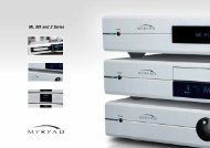
EZ-PAD GANG CONFIGURATIONS<br />
The <strong>MZC</strong>-<strong>88</strong> System comes with eight, pre-configured, single-gang MKP-8.1 EZ-Pads, as shown in Figure 1. (Decorator style<br />
cover plates are not included. Screw-less “Snap-On” type cover plates can also be used. Double and triple-gang keypad configurations<br />
are optional.)<br />
Each keypad comes with a set of factory installed “default buttons” plus a good variety of additional buttons for changes<br />
to the default configuration. The default buttons can be easily changed to meet the needs of any installation. Additional<br />
buttons are available separately for purchase. See the <strong>SpeakerCraft</strong> catalog and price sheets for the latest availabilities or call<br />
<strong>SpeakerCraft</strong> Customer Service.<br />
TNR1<br />
TNR2<br />
SAT<br />
CD<br />
1 2 3<br />
TNR1<br />
TNR2<br />
1 2 3<br />
GUIDE<br />
MENU<br />
SAT<br />
CD<br />
VCR<br />
DVD<br />
4 5 6<br />
SAT<br />
CD<br />
4 5 6<br />
SEL<br />
VCR<br />
CBL<br />
DVD<br />
AUX<br />
7 8 9<br />
TRK 0 DSC<br />
VCR<br />
CBL<br />
DVD<br />
AUX<br />
7 8 9<br />
TRK 0 DSC<br />
ESC<br />
INFO<br />
MUTE<br />
MUTE<br />
RDM<br />
MUTE<br />
RDM<br />
PLAY<br />
PWR<br />
PWR<br />
GRP<br />
PWR<br />
GRP<br />
MKP-8.1<br />
(Eight included with <strong>MZC</strong>-<strong>88</strong>)<br />
Single Gang<br />
MKP-1.0 NKP-1.0<br />
(optional)<br />
Two Gang<br />
MKP-8.1 NKP-1.0 FKP-1.0<br />
(optional)<br />
Three Gang<br />
Figure 1<br />
EZ-Pad Gang Configurations
F0123456789ABCDE<br />
F0123456789ABCDE<br />
Page 8<br />
<strong>MZC</strong>-<strong>88</strong> Installation Instructions<br />
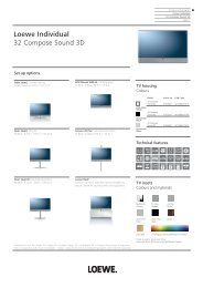
EZ-PAD FEATURE DESCRIPTIONS<br />
EZ-Pads come in four basic modules as shown. The MKP-1.0, MKP-8.1 and MKP-1.1 are Master Keypads and one must be<br />
used in each <strong>MZC</strong>-<strong>88</strong> Zone using a keypad. The <strong>MZC</strong>-<strong>88</strong> comes with eight pre-configured MKP-8.1’s. For convenience, it is<br />
usable right “out of the box” in conjunction with a default project that is factory programmed into the <strong>MZC</strong>-<strong>88</strong>. The MKP-8.1<br />
and MKP-1.1 feature a built-in IR receiver and have one less function button than the MKP-1.0, but are otherwise identical.<br />
The NKP-1.0 Numeric and FKP-1.0 Function key modules may be thought of as “slaves” to the Master Keypad (they will not<br />
work alone), providing more buttons for additional numeric and function commands.<br />
1 2 3 4<br />
5<br />
SAT<br />
VCR<br />
CD<br />
DVD<br />
+RELAY<br />
KEYPAD EXPANSION<br />
- RELAY<br />
ADDRESS<br />
MKP-1.0<br />
J-Box EZ-Pad<br />
- Master -<br />
<strong>SpeakerCraft</strong> ®<br />
+12V<br />
IR/IO<br />
GND<br />
485 A<br />
485 B<br />
6<br />
7<br />
TNR1<br />
SAT<br />
VCR<br />
CBL<br />
TNR2<br />
CD<br />
DVD<br />
AUX<br />
+RELAY<br />
KEYPAD EXPANSION<br />
- RELAY<br />
ADDRESS<br />
MKP-8.1<br />
J-Box EZ-Pad<br />
w/IRC<br />
- Master -<br />
<strong>SpeakerCraft</strong> ®<br />
+12V<br />
IR/IO<br />
GND<br />
485 A<br />
485 B<br />
MUTE<br />
MUTE<br />
PWR<br />
PWR<br />
8<br />
Rear View<br />
4<br />
9<br />
MKP-1.0 Master<br />
(Not included with <strong>MZC</strong>-<strong>88</strong>)<br />
1.77"<br />
Rear View<br />
MKP-8.1 Master<br />
(Included with the <strong>MZC</strong>-<strong>88</strong> and has an IR Receiver)<br />
9<br />
2<br />
1 2 3<br />
GUIDE<br />
MENU<br />
4 5 6<br />
7 8 9<br />
TRK 0 DSC<br />
KEYPAD EXPANSION<br />
4.07"<br />
ESC<br />
SEL<br />
INFO<br />
KEYPAD EXPANSION<br />
RDM<br />
GRP<br />
NKP-1.0<br />
J-Box EZ-Pad<br />
- Numeric -<br />
<strong>SpeakerCraft</strong> ®<br />
PLAY<br />
FKP-1.0<br />
J-Box EZ-Pad<br />
- Function -<br />
<strong>SpeakerCraft</strong> ®<br />
Rear View<br />
NKP-1.0 Numeric<br />
(Not included with <strong>MZC</strong>-<strong>88</strong>)<br />
Rear View<br />
FKP-1.0 Function<br />
(Not included with <strong>MZC</strong>-<strong>88</strong>)<br />
Figure 2<br />
EZ-Pad Features<br />
1. MKP-1.0/MKP-8.1 SOURCE/FUNCTION BUTTONS – Any of this set of eight buttons can be programmed as a<br />
Source Select or transport/function button for the <strong>MZC</strong>-<strong>88</strong>. One of the eight must always be designated as a Source<br />
Button. When the system is off, all buttons have a background green color. When a source button is pressed, it turns to<br />
a low-level red color to show the active source and the system is on in that zone.<br />
2. KEYPAD EXPANSION TERMINAL – This 16-pin header terminal is used to inter-connect EZ-Pad modules for expansion<br />
as needed. A 3-connector ribbon cable is packed with each NKP-1.0 and FKP-1.0 module for making these connections.<br />
3. ADDRESS SWITCH – An unique hex address must be set for each Master Keypad when connected on a common bus<br />
within a single zone. Unique addresses are not required zone-to-zone. It provides up to 16 addresses (0 to F).<br />
4. SNAP TABS – These tabs hold the decorator style insert panel to the metal mounting plate and are easily released for<br />
changing buttons.
<strong>MZC</strong>-<strong>88</strong> Installation Instructions<br />
Page <br />
5. MOUNTING PLATE – Standard plate allows the keypad module to be attached to standard in-wall J-Boxes using the 2<br />
screws provided. Also allows attachment of standard and screw-less, snap-on decorator type cover plates.<br />
6. IR RECEIVER LENS – The MKP-8.1 includes <strong>SpeakerCraft</strong>’s exclusive ANS (Ambient Noise Suppressor) IR Receiver, built-in.<br />
The IR Receiver allows use of a handheld remote for control of the system and IR controlled source components.<br />
7. EZ-CONNECT TERMINALS – These seven spring-loaded terminals accept wire sizes 14 to 28 AWG for connection of<br />
the following:<br />
• +RELAY/–RELAY – For connection of the external EPR-1.0 EZ-Pad Relay Speaker Muting Module. (Refer to.. .<br />
Designated Relay Mute Key section and Figures 6 & 19).<br />
• +12V DC – Powers the Keypad, including the internal IR Receiver on models MKP-8.1 and MKP-1.1.... .<br />
Includes reverse voltage protection.<br />
• IR/IO – Sends IR control signals for control of system components.<br />
• GND – Return for Power, IR signal and Data.<br />
• 485 A/485 B – Balanced, bi-directional system communications data.<br />
8. FUNCTION BUTTONS – These lower 5 buttons (4 buttons on the MKP-8.1) are primarily used for volume, mute and<br />
power, but can also be programmed for any function except source select. These buttons glow a low-level background<br />
green and do not change color when pressed. Button background lighting can be programmed to go off after a set<br />
time of inaction, or stay on continuously as programmed in EZ-Tools.<br />
9. NUMERIC AND FUNCTION BUTTONS – These buttons are used for direct numeric access of discs and tracks, selection<br />
of tuner presets, transport functions and menu navigation. All numeric and function buttons, including those on<br />
the Master Keypads, glow a low-level background green and do not change color when pressed. This background<br />
lighting can be programmed to go off after a set time of inaction, or stay on continuously as programmed in EZ-Tools.
Page 10<br />
<strong>MZC</strong>-<strong>88</strong> Installation Instructions<br />
FEATURE DESCRIPTIONS<br />
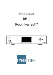
<strong>MZC</strong>-<strong>88</strong> FRONT PANEL<br />
The <strong>MZC</strong>-<strong>88</strong> is an 8-Zone, 8-Source A/V Amplifier Controller. It serves as the “brains” of the entire keypad system and provides<br />
audio/video switching and control for six external sources and two on-board AM/FM Tuners. Sixteen 50W/channel digital<br />
audio power amplifiers provide clean, powerful audio for up to eight zones.<br />
The Front Panel features two large displays, one for each of the on-board AM/FM Tuners. All tuner programming is done with<br />
the front panel tuner function buttons. Zone ON/OFF Status is also displayed on the front panel to show system activity.<br />
The Rear Panel is neatly laid out to provide clear access for all system control, audio, video, paging and trigger connections.<br />
System Programming can be done from connections on either the Front or Rear Panels. An IR Capture Eye is provided on the<br />
Front Panel for on-site learning of IR codes not included in the IR Code Library.<br />
1 3 4 6 7 8 10 11 13<br />
14 15<br />
2 5 9 12<br />
16 17 18 19 20 21<br />
1. ZONE STATUS LED INDICATORS AND LABELS – Eight, green LEDs, illuminate to show active zones and turn off<br />
when zones are off. Indented spaces accept adhesive backed labels for zone/room identification. A sheet of descriptive<br />
labels, typical of room or area names used in homes, is included.<br />
2. RDS BUTTON — Enables/disables Tuner 1 Radio Data System information. RDS displays station frequency, call letters,<br />
broadcast genre and time.<br />
3. MN/ST BUTTON — Toggles Tuner 1 FM stereo/mono modes. Mono can be useful for cleaning up background noise<br />
on hard to tune channels.<br />
4. AM/FM BUTTON — Toggles Tuner 1 AM and FM bands.<br />
5. ZONE BUTTON — Selects Tuner 1 Zone for programming and selecting Presets.<br />
6. TUN +/- — Changes Tuner 1 frequency UP/DOWN when pressed.<br />
Figure 3<br />
<strong>MZC</strong>-<strong>88</strong> Front Panel Features
<strong>MZC</strong>-<strong>88</strong> Installation Instructions Page 11<br />
7. TUNER 1 DISPLAY — LCD shows Tuner 1 status by: Zone, Band, Frequency, Preset, Mode and Frequency Lock.<br />
8. PRESETS — Tuner 1 Presets 1-10. Press to select preset for programming or channel preset select by zone.<br />
9. RDS BUTTON — Enables/disables Tuner 2 Radio Data System information. RDS displays station frequency, call letters,<br />
broadcast genre and time.<br />
10. MN/ST BUTTON — Toggles Tuner 2 FM stereo/mono modes. Mono can be useful for cleaning up background noise<br />
on hard to tune channels.<br />
11. AM/FM BUTTON — Toggles Tuner 2 AM and FM bands.<br />
12. ZONE BUTTON — Selects Tuner 2 Zone for programming and selecting Presets.<br />
13. TUN +/- — Changes Tuner 2 frequency UP/DOWN when pressed.<br />
14. TUNER 2 DISPLAY — LCD shows Tuner 2 status by: Zone, Band, Frequency, Preset, Mode and Frequency Lock.<br />
15. PRESETS — Tuner 2 Presets 1-10. Press to select preset for programming or channel preset select by zone.<br />
16. MASTER POWER SWITCH — When pressed to the in position, the <strong>MZC</strong>-<strong>88</strong> is placed in the power ON standby condition,<br />
permitting individual zones to be turned ON and OFF by keypad, IR remote or touch panel commands. In the<br />
OFF (out) position, power from the AC mains is completely turned off.<br />
17. MASTER POWER LED — Indicates when the Master Power switch is in the depressed position and that power has<br />
been applied from the AC mains.<br />
18. CONTROL PORT — One, 4 circuit 3.5mm mini jack connects to a PC running EZ-Tools for system programming and<br />
Firmware upgrades.<br />
19. FIRMWARE UPGRADE — One, two position switch enables the <strong>MZC</strong>-<strong>88</strong> Control Port for Firmware Upgrades instead<br />
of normal system program.<br />
20. IR CAPTURE — IR learning eye used with EZ-Tools to learn IR Codes not found in the embedded IR Code Library.<br />
21. ACTIVITY INDICATOR — Flashes when the system is learning IR commands or executing system functions.
Page 12<br />
<strong>MZC</strong>-<strong>88</strong> Installation Instructions<br />
<strong>MZC</strong>-<strong>88</strong> REAR PANEL<br />
1 2 3 4 5 6 7 8 9 10 11 12 13<br />
10<br />
14 15 16 17 18 19 20 21 22 23<br />
Figure 4<br />
<strong>MZC</strong>-<strong>88</strong> Rear Panel Features<br />
1. 8-ZONE KEYPAD INPUTS — One, SCSI terminal connects to a <strong>SpeakerCraft</strong> KCM-1.0 EZ-Connect Keypad Module<br />
for connection of zone keypads and IR sensors.<br />
2. CONTACT CLOSURE — Two, single pole dry relay contacts used to activate any device that can be controlled or triggered<br />
by a switch closure. These closures can be programmed within EZ-Tools to be activated by keypad presses, EZ-<br />
Code IR, or within macro commands for Momentary, Toggle and Open/Close Paired operations. Spring loaded terminals<br />
accept wire sizes from 28 to 14 AWG. Internal relay contacts are rated at 2A/30V AC or DC.<br />
3. EXPANSION PORT/LOOP — Two, RJ45 jacks primarily used for looping system data to multiple <strong>MZC</strong>-<strong>88</strong>’s in expanded<br />
systems. These jacks can also be used for connection of specialized RS485 controlled products.<br />
4. RS232 DATA I/O — One, DB9F terminal allows the <strong>MZC</strong>-<strong>88</strong> to control certain RS232 compatible devices such as<br />
source components and lighting systems.<br />
5. CONTROL PORT — One, 3.5mm 4-circuit mini jack allows several control functions. All Controller and keypad programming<br />
is accomplished via this port when connected to a PC running EZ-Tools with the optional 3.5MM PLUG<br />
TRANSFER CABLE. It also accommodates factory firmware upgrades in conjunction with the FIRMWARE UPGRADE<br />
OFF/ON SWITCH on the Front Panel of the <strong>MZC</strong>-<strong>88</strong>. The Firmware Upgrade Switch should be in the OFF position at all<br />
times, except, as instructed within EZ-Tools, when performing a firmware upgrade. Such upgrades ensure that the <strong>MZC</strong>-<br />
<strong>88</strong> has the latest functionality improvements without having to be shipped back to the factory. Another function of this<br />
port is to control installed system components with bi-directional data via touch panels or computers using RS232 protocol.<br />
NOTE: The 3.5mm Plug Transfer Cable would typically be connected to the DB9 COM Port on a PC. For computers<br />
that do not have a DB9 COM Port, use the optional USB/SERIAL ADAPTER CABLE. When using a USB port, connect<br />
the USB/Serial Adapter and the 3.5mm Transfer Cable together. Connect one end to a USB port on the PC and the<br />
other end of the assembled cable to the Control Port on the <strong>MZC</strong>-<strong>88</strong>.<br />
6. PHONE PAGE IN — One, RCA jack provides input for line level audio source such as telephone systems, door mics<br />
or other audio paging sources. This jack is programmable in EZ-Tools, to turn on as an event, when triggered by the<br />
DOORBELL/STATUS IN Jacks, item 8.
<strong>MZC</strong>-<strong>88</strong> Installation Instructions Page 13<br />
7. VIDEO PAGE IN — One, RCA jack provides input for composite video from doorbell paging systems, cameras or<br />
other composite video sources. This jack is programmable in EZ-Tools, to turn on as an event, when triggered by the<br />
DOORBELL/STATUS IN Jacks, item 8.<br />
8. DOORBELL/STATUS IN 1 & 2 — Two, 3.5mm mini jack trigger inputs work in conjunction with the PHONE/VIDEO<br />
PAGE IN jacks, items 6 & 7. When triggered, the Phone and/or Video inputs can be turned on in selected zones as<br />
programmed in EZ-Tools. If Audio or Video paging is not required, these jacks can also be programmed as STATUS<br />
INPUTS for power management of Source or Zone components. POLARITY: TIP= +V; SLEEVE=GND. INPUT VOLTAGE:<br />
3-30V AC or DC to trigger the ON condition. Voltage must drop below 1V AC or DC for OFF.<br />
9. COMMON IR OUTPUT — One, 3.5mm mini jack outputs all IR commands from IR sensors and Keypads regardless of<br />
zone origin. POLARITY: TIP=SIGNAL; SLEEVE=GND.<br />
10. HI/LO SWITCH — One, two position switch, sets high or low IR power output to the Common IR Output jack. Set to<br />
the LO setting when driving standard low power emitters (<strong>SpeakerCraft</strong> IRE-1.0, 2.0, 3.0 and 4.0). Set to HI when driving<br />
a high power emitter (<strong>SpeakerCraft</strong> IRE-5.0 Blaster) for teaching IR commands into learning remotes. HI OUTPUT:<br />
110mA; LO OUTPUT: 13mA. CAUTION: The HI position will smoke low power emitters!<br />
11. COMMON STATUS OUT — One, 3.5mm mini jack will go high (+12V DC) when any zone is turned ON and will go<br />
LOW (under 1V DC) when the last zone is turned OFF. POLARITY: TIP=+12V DC; SLEEVE=GND. MAX OUTPUT: 100<br />
mA at 9.5V DC.<br />
12. STATUS IN — Six, 3.5mm mini jack trigger inputs primarily used for power management of common source components<br />
that do not have discreet IR ON/OFF codes. These jacks sense constant voltage to determine the ON/OFF state<br />
of the sensed component. Typically, a current sensing device with a 12V DC output would be used to let the <strong>MZC</strong>-<strong>88</strong><br />
know when a component is ON or OFF. The <strong>MZC</strong>-<strong>88</strong> will then appropriately send or not send an IR ON/OFF toggle<br />
command to that component when that source is selected or when the system is being shut down. ON/OFF conditions<br />
are programmed in EZ-Tools as Keypad macros or system events. When not used for power management, these<br />
jacks can be used to trigger events such as IR macros, switch closures and initiate RS232 commands. POLARITY:<br />
TIP=+V; SLEEVE=GND. INPUT VOLTAGE: 3-30V AC or DC to trigger the ON condition. Voltage must drop below 1V<br />
AC or DC for OFF.<br />
13. FM/AM/75Ω — One, F-type terminal, connects to a <strong>SpeakerCraft</strong> HED-1.0 Masthead Amplifier. The HED-1.0 should be<br />
located away from the system components to reduce RF interference and improve reception. FM Dipole and AM Loop<br />
antennas connect to the HED-1.0. The HED-1.0 connects to the <strong>MZC</strong>-<strong>88</strong> via RG6 coaxial cable terminated with F-type<br />
connectors on runs up to 100’. CAUTION: Do not connect an antenna directly to this terminal. There is DC voltage<br />
present to power the HED-1.0. This voltage will interfere with antenna performance and possibly cause electrical short if<br />
not terminated properly.<br />
14. IR OUT (Source) — Six, 3.5mm mini jacks, one per Source, output IR commands to external common source components.<br />
When a source is selected, from a keypad or remote control, IR commands are routed directly to that source.<br />
This allows selective control of multiple same-brand, same-model source components (multiple Satellite Receivers, DVD<br />
Players etc). POLARITY: TIP=SIGNAL; SLEEVE=GND.<br />
15. IR LOOP — Six, 3.5mm mini jacks, one per Source, provide connections for an IR signal path for external common<br />
source components, when using multiple <strong>MZC</strong>-<strong>88</strong>s in expanded systems. i.e. If using two <strong>MZC</strong>-<strong>88</strong>s, the SOURCE IR<br />
OUTS on the <strong>MZC</strong> Slave unit would connect to the appropriate SOURCE IR LOOPS on the <strong>MZC</strong> Master unit to pass<br />
Source IR commands between controllers from expanded zones. The IR OUTS on the Master connect to IR EMITTERS<br />
attached to the source components for source IR control from all zones. POLARITY: TIP=SIGNAL; SLEEVE=GND.<br />
16. L, R & V INPUT (Source Left/Right Audio & Video Input) — Eighteen RCA jacks, three for each Source, provide<br />
left and right line-level audio and composite video signal inputs for up to six external common source components.<br />
17. L,R & V LOOP (Source Left/Right Audio & Video Loop) — Eighteen, RCA jacks, three per Source, provide buffered<br />
left and right line-level audio and composite video outputs that are typically used to loop Source A/V signals to additional<br />
zone inputs on Slave <strong>MZC</strong>-<strong>88</strong>’s in expanded systems. i.e. The L, R, V LOOP on the <strong>MZC</strong> Master would connect to<br />
the appropriate L,R,V INPUT on <strong>MZC</strong> Slave 1. Slave 1 would then loop to Slave 2, etc. These outputs can also be used<br />
to drive local components, such as a local surround receiver, when not used for expansion.
Page 14<br />
<strong>MZC</strong>-<strong>88</strong> Installation Instructions<br />
18. L & R PRE-OUT — Two, RCA jacks, one pair per Zone, provide left and right line-level audio outputs for driving external<br />
high-power/audiophile two-channel amplifiers in large or outdoor zones or a critical listening zone, or driving a<br />
multi-channel amplifier for additional rooms, (sub-zone expansion) where needed.<br />
19. IR OUT (Zone) — One, 3.5mm mini jack, one per zone, provides dedicated Zone IR output for exclusive control of a<br />
specific zone component. (i.e., a dedicated satellite receiver or DVD player, that cannot be controlled from any other<br />
zones). POLARITY: TIP=SIGNAL; SLEEVE=GND.<br />
20. L & R SPEAKERS — Eight, removable screw-down connectors, one terminal per zone, provide quick connection of the<br />
internal amplifiers to Zone stereo speaker pairs. WIRE GAUGE: 14 to 28 AWG.<br />
WARNING: The power amplifiers in the <strong>MZC</strong>-<strong>88</strong> use Bridged (BTL) outputs. Speaker connections must be completely<br />
separate for each channel and have NO common ground connections through any connected Speaker Selectors, VCs,<br />
Test Equipment, etc. Failure to observe this may cause damage and void the warranty.<br />
21. VIDEO OUTPUT — Eight, F-type terminals, one per zone, provide a dedicated composite video output for each zone.<br />
75 ohm outputs provide matched line impedance for high quality video over RG6 cable for lengths up to 500 feet.<br />
22. VC/NVC — Eight, two-position switches, one per zone, switch the PRE-OUT jacks to VC - internal Volume Control (variable,<br />
zone volume controlled by keypads or IR remote) or NVC - No Volume Control (fixed, zone volume controlled by<br />
in-wall volume control or volume control on an external device such as an A/V Receiver). In either case, the tone control<br />
action remains available for room “EQ” settings.<br />
23. IEC TYPE AC MAINS RECEPTACLE AND FUSE — One, Standard IEC 3-conductor AC line cord receptacle, connects to<br />
included AC power cord. Also houses the rear panel replaceable AC mains fuse (T6.3AL 250V).
<strong>MZC</strong>-<strong>88</strong> Installation Instructions Page 15<br />
KCM-1.0 EZ-CONNECT KEYPAD MODULE<br />
The KCM-1.0 is an 8-Zone connection interface for EZ-Pads and IR receivers when used to control a <strong>MZC</strong>-<strong>88</strong>. Given the connection<br />
flexibility of the <strong>MZC</strong>-<strong>88</strong>, the KCM-1.0 provides EZ access to Keypad and IR receiver wiring without interfering with<br />
other system connections. The KCM-1.0 and SCSI cable are included with the <strong>MZC</strong>-<strong>88</strong><br />
1<br />
2<br />
3 4 3<br />
Figure 5.<br />
KCM-1.0 EZ-Connect Keypad Module<br />
1. SCSI CABLE — One, 1 meter SCSI latching connector cable. Connects the 8-ZONE KEYPAD OUTPUTS Terminal on<br />
a KCM-1.0 to the 8-ZONE KEYPAD INPUTS Terminal on a <strong>MZC</strong>-<strong>88</strong> Controller for Keypad connection. When multiple<br />
<strong>MZC</strong>-<strong>88</strong> Controllers are used in expanded systems, one KCM-1.0 is required for EACH <strong>MZC</strong>-<strong>88</strong>.<br />
2. 8-ZONE KEYPAD OUTPUTS — One, SCSI Terminal connects to a <strong>MZC</strong>-<strong>88</strong> via the included SCSI Cable. Provides a twoway<br />
interface for system control and status between Keypads and the <strong>MZC</strong>-<strong>88</strong>.<br />
3. MOUNTING SCREW HOLES — Two, countersunk screw holes for mounting the KCM-1.0 to a wall or shelf.<br />
4. EZ-CONNECT KEYPAD TERMINALS — Eight sets of five spring-loaded terminals, accept wire sizes 14 to 28 AWG for<br />
connection of the following:<br />
• +12V DC — Powers the Keypad, including the internal IR Receiver on models MKP-8.1 and MKP-1.1.<br />
• IR IN — IR signal input from keypad’s IR receiver.<br />
• GND — Return for Power, IR signal and Data<br />
• 485 A/485 B — Balanced, bi-directional system communications data.
Page 16<br />
<strong>MZC</strong>-<strong>88</strong> Installation Instructions<br />
EPR-1.0 EZ-PAD RELAY MUTING MODULE<br />
The EPR-1.0 EZ-Pad Speaker Muting Relay Module allows local speaker muting in any room with an EZ-Pad. Example: An<br />
<strong>MZC</strong>-<strong>88</strong> Zone PRE-OUT feeding a multi-channel amplifier for sub-zone expansion. Each of the additional ‘rooms’ would utilize<br />
one stereo pair speaker-level output from the multi-channel amp, have an EZ-Pad for system and source control and each<br />
keypad would have an EPR-1.0 to mute the local speakers. All rooms in the zone would have the same ON/OFF status and<br />
play the same source. Individual room mute could then be controlled either from a keypad or an appropriately programmed<br />
IR Remote.<br />
1<br />
2<br />
4<br />
3<br />
1<br />
Figure 6.<br />
EPR-1.0 EZ-Pad Relay Features<br />
1. MOUNTING HOLES — Two, keyholes, use these holes to mount the EPR-1.0 to any flat surface (usually to the studding<br />
in the wall behind the EZ-Pad or the in-wall speakers).<br />
2. “AMPLIFIER” EZ-CONNECT TERMINALS — Four, spring-loaded terminals connect to the amplifier L & R speaker<br />
level output terminals. WIRE GAUGE: 14 to 28 AWG.<br />
3. “SPEAKERS” EZ-CONNECT TERMINALS — Four, spring-loaded terminals connect to the L & R terminals on the room<br />
speakers. WIRE GAUGE: 14 to 28 AWG.<br />
4. RELAY COIL LEADS — This 12" (305mm) 2-conductor lead connects to the +Relay and –Relay terminals on the back<br />
of the EZ-Pad. It can be extended to any length required (2000’ with 24 AWG wire). Maintain proper polarity. When the<br />
designated MUTE key on the EZ-Pad is pressed, the EPR-1.0 relay opens, thus muting the audio. The selected source button<br />
on the EZ-Pad will blink at a slow rate to indicate the muted condition.
<strong>MZC</strong>-<strong>88</strong> Installation Instructions Page 17<br />
HED-1.0 MASTHEAD AMPLIFIER<br />
The HED-1.0 Masthead Amplifier provides remote connection for the AM and FM antennas used with the <strong>MZC</strong>-<strong>88</strong>. The HED-<br />
1.0 can be located up to 100’ away from the <strong>MZC</strong> and other system components, reducing RF interference therby improving<br />
reception and reducing noise. Lenghts longer than 100’ can be used, but expect reduction in tuner sensitivity in proportion<br />
to cable length.<br />
1<br />
2<br />
2<br />
3 4<br />
Figure 7<br />
HED-1.0 Masthead Amplifier<br />
1. FM/AM — One, F-type terminal connects to the FM/AM/75Ω terminal on a <strong>MZC</strong>-<strong>88</strong> Rear Panel via RG6 coaxial cable.<br />
FM and AM broadcast reception is output from this terminal and fed to the appropriate tuner section (AM or FM) inside<br />
the <strong>MZC</strong>-<strong>88</strong>. Tuner 1 and Tuner 2 are both fed from this connection.<br />
NOTE: The HED-1.0 is phantom powered via this terminal from the <strong>MZC</strong>, so the run of RG6 must be an unbroken run<br />
with no splits or RF amplifiers.<br />
2. FLANGE SCREW HOLES — Two, screw holes for mounting the HED-1.0 to a stud or wall surface.<br />
3. AM ANTENNA TERMINAL — Two, spring clip terminals for connecting the included AM Loop Antenna. POLARITY:<br />
non-critical.<br />
4. FM ANTENNA TERMINAL — One, F-type terminal for connecting the included FM Dipole Antenna.
Page 18<br />
<strong>MZC</strong>-<strong>88</strong> Installation Instructions<br />
LTM-1.0 LEARN/TEST MODULE AND TRANSFER/ADAPTER CABLES<br />
The LTM-1.0 Kit (optional) come packaged together and include the items illustrated in Figure 8.<br />
Figure 8<br />
EZ-Tools, LTM-1.0 and Cables Package<br />
<strong>SpeakerCraft</strong> EZ-TOOLS is a Windows®-based software program. It is available as a free download from www.speakercraft.<br />
com. EZ-Tools provides for the complete configuring and programming of <strong>MZC</strong> Series Multi-Zone Controllers and EZ-Pad<br />
control systems.<br />
Some of its many features include: Key button choice and placement, single and multiple zone assignments, Command<br />
Library, IR learning and testing capability in conjunction with the LTM-1.0, single and macro command programming, status/power<br />
management, priority commands management, code length timing, delay settings, events programming, etc.<br />
The LTM-1.0 LEARN/TEST MODULE is primarily an installer’s tool and serves as an IR learning, IR teaching and IR command<br />
test module. (Refer to Figure 9) It includes blaster emitters so that learning remotes, used in conjunction with EZ-<br />
Pads, can be programmed with system IR commands. Also, special <strong>SpeakerCraft</strong> EZ-Codes are similarly taught so that keypad<br />
sources track automatically with sources selected by the remote.<br />
NOTE: See item 5 on page 8 for details regarding use of the 3.5MM PLUG TRANSFER CABLE and the USB/SERIAL<br />
ADAPTER CABLE.
<strong>MZC</strong>-<strong>88</strong> Installation Instructions Page 19<br />
1 2 3 4<br />
5<br />
6<br />
11<br />
10<br />
9<br />
8<br />
7<br />
12<br />
Figure 9<br />
LTM-1.0 Learn/Test Module Features<br />
1. RS232 PORT — One, DB9M jack outputs RS232 commands for testing control of RS232 controlled system components.<br />
2. EXPANSION PORTS — Two, RJ45 jacks provide connections for testing control of future RS485 controlled products.<br />
3. CONTROL PORT — One, 3.5mm 4-circuit mini jack is a serial port that provides several control functions. All command<br />
learning and testing functions are accomplished via this port, using EZ-Tools, in conjunction with the 3.5MM PLUG<br />
TRANSFER CABLE. Firmware upgrades for the LTM-1.0 are also accomplished via this port.<br />
NOTE: The 3.5mm Plug Transfer Cable would typically be connected to the DB9 COM Port on a PC. For computers<br />
that do not have a DB9 COM Port, use the USB/SERIAL ADAPTER CABLE (Refer to Figure 8). When using a USB port,<br />
connect the USB/Serial Adapter and the 3.5mm Transfer Cable together. Connect one end to a USB port on the PC<br />
running EZ-Tools and the other end of the assembled cable to the Control Port on the <strong>MZC</strong>-<strong>88</strong>.<br />
4. +12V DC REGULATED — One, 2.1mm coaxial jack provides connection for a <strong>SpeakerCraft</strong> PS-1.0 12V DC 200mA<br />
power supply (included). POLARITY: PIN=+12V DC; SLEEVE=GND.<br />
5. PROGRAMMING SWITCH — One, (upper) DIP switch DISables or ENables LTM-1.0 firmware upgrades. Leave this<br />
switch in the DIS position at all times, unless performing a LTM-1.0 firmware upgrade. Such upgrades are accomplished<br />
via EZ-Tools with the CONTROL PORT (item #3) connected to a PC running EZ-Tools. (This switch setting is for firmware<br />
upgrades to the LTM-1.0 only.)<br />
6. SENSE SWITCH — One, (lower) DIP switch sets the sensitivity of the internal IR Learning Sensor. This switch should<br />
normally be set in the LO position. If the teaching remote has weak output, it should be switched to the HI position.
Page 20<br />
<strong>MZC</strong>-<strong>88</strong> Installation Instructions<br />
7. POWER — Red LED indicates power supply is connected and the LTM-1.0 is active.<br />
NOTE: If the Firmware Switch is set to ON the red power LED will not light.<br />
8. LEARNING SENSOR — Internal IR sensor receives IR command data from external handheld remotes for learning IR<br />
commands that are not available in the EZ-Tools IR command library. Point the “teaching” remote at this lens from a distance<br />
of about 1 to 4 inches when “learning” IR commands.<br />
9. BLASTER EMITTERS — These high power emitters output IR commands for testing and “teaching” purposes. When<br />
testing commands, the Blaster Emitters should be pointing toward the device(s) to be controlled. The devices being<br />
tested can be 30 feet or more away, with no obstructions. When “teaching” IR commands to a learning remote, point<br />
the “learning” remote toward these emitters at a distance of about 1 to 4 inches.<br />
NOTE: These Blaster Emitters are automatically disabled whenever an emitter or any 3.5mm mini plug is inserted into<br />
the IR OUT jack (item #11).<br />
10. ACTIVITY INDICATOR — Green LED, indicates IR learning mode activities. Also flashes during activation of internal<br />
command data.<br />
11. IR OUT — 3.5mm 2-circuit mini jack will drive any <strong>SpeakerCraft</strong> or other compatible emitters at medium power levels<br />
for operational tests of IR commands. It will also drive one AT-1.0 Terminator block for connecting additional to test multiple<br />
devices.<br />
NOTE: The Blaster Emitters (item #9) are automatically disabled whenever a 3.5mm mini phone plug is inserted into<br />
this jack.<br />
12. NON-SKID FOOT PADS
<strong>MZC</strong>-<strong>88</strong> Installation Instructions Page 21<br />
(Optional) (Optional) (Optional)<br />
14AWG<br />
Earth<br />
Ground<br />
(See Text)<br />
Figure 10<br />
Typical <strong>MZC</strong>-<strong>88</strong> System
Page 22<br />
<strong>MZC</strong>-<strong>88</strong> Installation Instructions<br />
SYSTEM PLANNING AND INSTALLATION<br />
SYSTEM PLANNING<br />
With all of the flexibility and options of a <strong>MZC</strong>-<strong>88</strong> System, careful planning can save time and money for both the installer<br />
and homeowner. A few EZ steps can help in managing this process.<br />
1. KNOW THE PRODUCT AND ALL OF ITS CAPABILITIES — This will help in making suggestions to the homeowner<br />
for incorporating features they may want. It will also help in being able to combat feature capabilities, or inadequacies,<br />
of a competitive product that another Installation Company may be proposing.<br />
2. KNOW THE HOMEOWNER — Spend some time in the home if possible, and get a feel for how the prospective client<br />
is going to want to use the system. If the home is in the planning stage, be sure to get involved with the architect to assure<br />
proper allocation of space for system components, ventilation and access to the system for service (a closet with rear<br />
access to the system connections is ideal whenever possible).<br />
3. DOCUMENT EVERYTHING — When discussing the system with the prospective client, write down all of their ‘wants’<br />
in terms of how they want the system to work. Do they want front doorbell paging with a camera? Do they have lots of<br />
parties and want to ‘group’ zones in common areas? Will they need an external high-powered amplifier for the patio/<br />
pool area?<br />
Write everything down and review it with the homeowner to define specific system features and functions. Suggest<br />
options for future upgrading or expansion of the system, such as additional wire infrastructure, for adding rooms to the<br />
system long after the walls have been sealed. Use the results of the review to create a formal proposal.<br />
4. LEAVE PRODUCT INFORMATION — Leave the client with Brochures for the <strong>MZC</strong>-<strong>88</strong>, <strong>SpeakerCraft</strong> Speakers, Amplifiers<br />
and Accessories that will be specified in the proposal. (Packaging it all in a nice folder or binder is a nice touch.)<br />
Confirm a date to review the formal proposal.<br />
5. CONTRACT THE JOB — Get back to the prospective client with a professional, formal proposal. (There are some good<br />
system planning and proposal software packages that can really help manage this whole process.) Review their ‘wants’<br />
and show how they have been implemented in the overall system design. Inform the homeowner as to how the installation<br />
will be done. Phase 1, pull wire. Phase 2, install speakers and components. Phase 3, system programming and<br />
tweaking. (Tying payments to the different installation phases is also something to consider. Spreading the payments can<br />
help defuse potential sticker shock for the homeowner and also help manage cash flow for the Installation Company.)<br />
If all is acceptable to the homeowner, have them sign the proposal as a formal contract and set a start date for work to<br />
begin. (Having the homeowner sign the proposal as a contract can help avoid problems during installation in that the<br />
system and work to be done is defined. Anything not defined in the contract is extra.)<br />
6. DOCUMENT THE SYSTEM FOR INSTALLATION — If using one of the planning and proposal software packages<br />
available from third parties, this part of the process will already be done. If not, carefully document the system for wholehouse<br />
wiring. Show all runs of CAT-5 for control, coax for video, two-pair 18-14AWG stranded for speakers and additional<br />
wires for doorbell/paging, and anything else in the system that needs to have wire pulled through the walls. Don’t<br />
leave anything out. The person pulling the wire isn’t necessarily the same person that sold the system, so if the system<br />
hasn’t been properly documented, critical feature wire components could be left out.<br />
Detail what components will be installed in each room, and where they will be installed, including the control system,<br />
speakers, TV/Video Display and any other sub-system interfaces by room, by component, by brand and by model. Be<br />
sure the person pulling the wire has this information to cross reference the wires pulled and to where.<br />
7. DOCUMENT SYSTEM FUNCTIONALITY — Document all system functions by system, by zone, by source and any<br />
special features that have been included. Be sure to include functions such as how the system turns on when the first<br />
source is selected, and how it turns off when the last zone shuts down. Include all special functions such as switch<br />
closures for lifts and screens and EPR-1.0 mute commands for zones with multi-channel amps for sub-zone expansion.
<strong>MZC</strong>-<strong>88</strong> Installation Instructions Page 23<br />
Include Tuner preset preferences by zone. Include Paging functions. All system functions should be detailed. The person<br />
doing the system programming isn’t necessarily the same person who sold the system or pulled the wire. Be sure everyone<br />
involved in the installation and setup knows what the system is and how it is supposed to work.<br />
8. ACQUIRE ALL SYSTEM COMPONENTS — Set up the system, and program and test all functions before taking the<br />
electronics to the job site. This can save valuable time in assuring that all system components work and the system is<br />
functioning as designed. Connecting and testing the system prior to installation will also help assure that all parts and<br />
pieces that will go into the system are in hand, so time is spent on the job site and not running around town shopping<br />
for parts or not being able to finish the installation while waiting for an air shipment of a ten dollar part.<br />
9. HEAD-END CONSIDERATIONS — The system head-end should be in a convenient, central location that provides<br />
easy access for the user, to be able to load discs, video tapes etc. The location should also be accessible for service and<br />
ideally would have either have rear access to the system connections or a pull-out rack that allows access to system<br />
connections. All system wire runs should terminate at the head-end. There should be sufficient mounting space for all<br />
system components and the wires and cables that connect them. Leave plenty of room for airflow for proper ventilation<br />
or system components could be damaged. Too tight of a space that does not leave room for system wiring or a poorly<br />
dressed system can cause thermal problems. Wires jumbled in around system components can act as an insulator or<br />
block free airflow which can damage the components from overheating. Incorporate a proper ventilation system using<br />
cooling fans for systems with external amplifiers or other components that generate excess heat. When possible, leave<br />
extra space for future expansion of the system for additional zone and source components.<br />
10. ZONE CONSIDERATIONS — Identify all room components and their locations. Typically, a keypad would be mounted<br />
near the entry to a room. If the room orientation of where the TV/Monitor and speakers are located leaves the keypad<br />
behind the user, an additional IR receiver on the same wall as the TV and speakers will help make controlling the system<br />
more user friendly. Be sure to include an appropriate wire run for the IR receiver. Additional wire runs for controlling lifts,<br />
screens and drapes should also be considered. Try to avoid mounting keypads and IR receivers in locations that will be<br />
exposed to direct sunlight. Leave extra wire at keypad and in-wall speaker locations so these components can be easily<br />
removed without pulling on wires and possibly have them fall down inside the wall, should service be necessary.
Page 24<br />
<strong>MZC</strong>-<strong>88</strong> Installation Instructions<br />
SYSTEM INSTALLATION<br />
WIRING<br />
Once the system has been defined and the contract signed, work can begin. The first part of the system to be installed is the<br />
wiring infrastructure. With all of the flexibility and options of a <strong>MZC</strong>-<strong>88</strong> System, maintaining clear, accurate documentation of<br />
the location (the house) and the system will help in managing a smooth installation. Always be sure to pull and test the wires<br />
needed for the system as specified, and always consider pulling extra wire for fall-back in the event something gets damaged<br />
during drywall installation. Beyond that, pulling additional wire to rooms not specified in the system can help down the road,<br />
should the homeowner decide to add rooms to the system at a later date, or increase flexibility within already active rooms.<br />
There are certain types of wire that are default requirements and there are others that are used for the system optional features.<br />
KEYPADS<br />
<strong>SpeakerCraft</strong> EZ-Pads have seven-position spring clip terminals for wire connections. Five of these terminals are used for<br />
connection to the KCM-1.0 EZ-CONNECT KEYPAD MODULE. CAT-5 can be used with or without RJ45 connectors. Standard<br />
wire can also be used for retro-fit installations provided there are at least 5 conductors available. Use of <strong>SpeakerCraft</strong><br />
RJA-1.1 RJ45 to Wire Pin Adaptors is recommended for both EZ Pad and KCM-1.0 CAT-5 connections.<br />
CAT-5 WITH RJ45 CONNECTORS<br />
Requirement - Pull home-runs of CAT-5 from each EZ-Pad location to the System Head-End.<br />
MAXIMUM LENGTH: 1000' (305m).<br />
Installation - Terminate the CAT-5 with RJ45 connectors on both ends. Be sure the terminations are identical on both<br />
ends, creating a pass-through configuration. Connect the CAT-5 cable to the keypads using <strong>SpeakerCraft</strong> RJA-1.1 RJ45-<br />
TO-WIRE PIN ADAPTERS. Insert the RJA-1.1 pins into the keypad’s EZ-Connect Terminals and snap the levers in place.<br />
RJA1.1’s can be used at both the keypad and KCM-1.0 ends, if desired. Be sure RJA1.1 pin orientation is correct on both<br />
ends prior to powering up the system.<br />
CAT-5 WITHOUT RJ45 CONNECTORS<br />
Requirement - Pull home-runs of CAT-5 from each EZ-Pad location to the System Head-End.<br />
MAXIMUM LENGTH: 1000' (305m).<br />
Installation - Strip away approximately 2” of the CAT-5 jacket and separate the individual conductors. Strip approximately<br />
1<br />
⁄4 inch on both ends of the individual conductors to be used for connection to the KCM-1.0. Twist the stripped ends so<br />
there are no loose strands that can cause shorts. Secure the ends to the EZ-Pad and KCM-1.0 terminals. Maintain proper<br />
polarity. The 3 unused leads of the CAT-5 cable can be connected in parallel, one, with each of the +12V, GND and IR/IO<br />
leads, for better IR performance when running long lengths of cable .<br />
STANDARD WIRE<br />
Requirement - Pull home-runs of 28-14AWG stranded, non-sheilded wire with at least 5 conductors to the System<br />
Head-End.<br />
MAXIMUM LENGTH: 1000’ (305m).<br />
Installation - Strip away approximately 2” of the wire jacket and separate the individual conductors. Strip approximately<br />
1<br />
⁄4 inch on both ends of the individual conductors to be used for connection to the EZ-Pads and KCM-1.0. Twist the<br />
stripped ends so there are no loose strands that can cause shorts. Secure the ends to the EZ-Pad and KCM-1.0 terminals.<br />
Maintain proper polarity. Unused leads can be connected in parallel, one, with each of the +12V, GND and IR/IO leads,<br />
for better IR performance when using lighter gauge wire on long runs.
<strong>MZC</strong>-<strong>88</strong> Installation Instructions Page 25<br />
VIDEO<br />
Requirement - Pull home runs of RG6 quad-shield coaxial cable from every TV/Video Display location to the System<br />
Head-End.<br />
MAXIMUM LENGTH: 500’.<br />
Installation - Terminate the head-end side with a male F-type connector to connect to the appropriate ZONE VIDEO<br />
OUT on the <strong>MZC</strong>-<strong>88</strong>.<br />
NOTE: The ZONE VIDEO OUT terminals on the <strong>MZC</strong>-<strong>88</strong> are F-type connectors that output COMPOSITE VIDEO. These<br />
should not be confused with F terminals that output RF signals. The zone end of the RG6 can be terminated with an RCA<br />
connector and connected directly to the TV/video display composite video IN or terminated with a male F-type connector<br />
and adapted to the RCA jack on the TV/video display.<br />
SPEAKERS<br />
Requirement - Pull home runs of 18-14AWG two-conductor quality stranded speaker wire from all speaker locations to<br />
the System Head-End.<br />
MAXIMUM LENGTH: 18AWG up to 50’; 16AWG up to 200’; 14AWG up to 1000’.<br />
Installation - Strip approximately 1 ⁄4” off each end of each conductor and twist the stripped ends so there are no loose<br />
strands that can cause shorts. On the Head-End side, carefully slide the individual conductors into the appropriate L+,L-/<br />
R-,R+ speaker terminals on the removable screw down connectors that plug into the <strong>MZC</strong>-<strong>88</strong> Zone Speaker OUT Terminals.<br />
Terminate the speaker ends as appropriate for the given speakers. Maintain proper polarity.<br />
WARNING: The power amplifiers in the <strong>MZC</strong>-<strong>88</strong> use Bridged (BTL) outputs. Speaker connections must be completely<br />
separate for each channel and have NO common ground connections through any connected Speaker Selectors, VCs,<br />
Test Equipment, etc. Failure to observe this may cause damage and void the warranty.<br />
CONTACT CLOSURES<br />
Requirement - Pull 28-14AWG two-conductor stranded wire from any location utilizing a contact closure from the <strong>MZC</strong>-<br />
<strong>88</strong> to the System Head -End.<br />
MAXIMUM LENGTH: Will vary with application.<br />
Installation - On the Head-End side, strip approximately 1 ⁄4” off each end of each conductor and twist the stripped ends<br />
so there are no loose strands that can cause shorts. Carefully slide the individual conductors into the appropriate Contact<br />
Closure Terminal pair on the <strong>MZC</strong>-<strong>88</strong> Rear Panel. Terminate the device end as appropriate. POLARITY: Head-End not<br />
critical.<br />
EXPANSION PORT/LOOP<br />
Requirement - CAT-5 cable terminated with RJ45 connectors, pass-through configuration (pin to pin).<br />
MAXIMUM LENGTH: 4000’<br />
Installation - Connect CAT-5 cables terminated with RJ45 connectors to <strong>MZC</strong>-<strong>88</strong> Port/Loop terminals in expanded systems.<br />
See section: Expanded Systems for additional information.<br />
RS232<br />
Requirement - Use a quality, pre-made Serial Cable terminated with DB9 connectors, pass-through configuration.<br />
MAXIMUM LENGTH: 50’<br />
Installation - Connect one end of the Serial cable to the RS232 DATA I/O Port on the <strong>MZC</strong>-<strong>88</strong> Rear panel and the other<br />
end to the device being controlled via RS232. NOTE: This connection requires configuration in EZ-Tools.<br />
CONTROL PORT<br />
Used for system programming and firmware updates. See section: Programming for additional information.
Page 26<br />
<strong>MZC</strong>-<strong>88</strong> Installation Instructions<br />
PHONE PAGE IN<br />
Requirement - Use a quality, pre-made audio cable terminated with RCA connectors for runs under 15’. Pull quality,<br />
shielded audio cable from the paging device to the System Head-End for runs up to 200’.<br />
MAXIMUM LENGTH: 200’<br />
NOTE: Some Telephone Control Panels can produce sufficient levels of RF radiation to interefre with <strong>MZC</strong>-<strong>88</strong> perfomance.<br />
It is recommended that Telephone Panels be located at least 15-20 feet from an <strong>MZC</strong>-<strong>88</strong> to avoid interference.<br />
Installation - Connect one end of the pre-made wire to the paging device line level audio out and the other to the<br />
PHONE PAGE IN jack on the <strong>MZC</strong>-<strong>88</strong> Rear Panel. Terminate the sheilded audio cable with an RCA connector at the<br />
System Head-End. Terminate the paging device end as appropriate. Maintain proper polarity. RCA CONNECTOR<br />
POLARITY: PIN=SIG; SLEEVE=GND.<br />
VIDEO PAGE IN<br />
Requirement - Use a quality, pre-made video cable terminated with RCA connectors for runs under 15’. Pull RG6 quadsheild<br />
coaxial cable from the camera/video device to the System Head-End for runs over 15’.<br />
MAXIMUM LENGTH: Will vary by device. See the specification of the device being used or call the equipment<br />
manufacturer. 40-50’ typical, up to 500’ on RG6 coaxial cable with some devices.<br />
Installation - Connect one end of the pre-made video cable to the camera/video device composite video out and the<br />
other to the VIDEO PAGE IN jack on the <strong>MZC</strong>-<strong>88</strong> Rear Panel. Terminate the RG6 with an RCA connector at the System<br />
Head-End. Terminate the camera/video device end as appropriate. Maintain proper polarity. RCA CONNECTOR<br />
POLARITY: PIN=SIG; SLEEVE=GND.<br />
DOORBELL/STATUS IN<br />
Requirement - Pull 28-22AWG two-conductor stranded wire from the doorbell or sensed device location to the System<br />
Head-End.<br />
MAXIMUM LENGTH: Will vary. 500’ typical, up to 2000’ with some devices.<br />
Installation - Terminate the 28-22AWG two-conductor wire with a 3.5mm mini plug at the System Head-End for<br />
connection to one of the two Doorbell/Status IN jacks on the <strong>MZC</strong>-<strong>88</strong> Rear Panel. Terminate the Doorbell/sensed device<br />
end as appropriate. MINI PLUG POLARITY: TIP=+12V; SLEEVE=GND.<br />
COMMON IR OUT<br />
Requirement - Use a <strong>SpeakerCraft</strong> standard emitter (IRE-1.0, 2.0, 3.0, 4.0) when the Common IR OUT Switch is set in<br />
the LO position. Use a <strong>SpeakerCraft</strong> high power emitter (IRE-5.0 Blaster) when the Common IR OUT Switch is set in the<br />
HI position. Pull 28-18AWG two-conductor stranded wire from the location requiring System Common IR Control to the<br />
System Head-End to extend the emitter wire as required.<br />
MAXIMUM LENGTH: 1000’<br />
Installation - Connect an emitter to the Common IR OUT on <strong>MZC</strong>-<strong>88</strong> Rear Panel and set the HI/LO switch as<br />
appropriate. Attach the emitter over the IR eye on the device to be controlled. When extending the emitter wire,<br />
terminate the 28-18AWG two-conductor wire with a 3.5mm mini plug at the System Head-End. Terminate the other end<br />
for System Common IR Control as appropriate. MINI PLUG POLARITY: TIP=SIG; SLEEVE=GND.<br />
COMMON STATUS OUT<br />
Requirement - Pull 28-18AWG two-conductor stranded wire from the device to be controlled to the System Head-End.<br />
MAXIMUM LENGTH: 1000’<br />
Installation - Terminate the 28-18AWG two-conductor wire with a 3.5mm mini plug at the System Head-End for<br />
connection to the Common Status OUT jack on the <strong>MZC</strong>-<strong>88</strong> Rear Panel. Terminate the controlled device end as<br />
appropriate. MINI PLUG POLARITY: TIP=+12V; SLEEVE=GND.<br />
STATUS IN<br />
Requirement - Pull 28-18AWG two-conductor stranded wire from the sensed device(s) to the System Head-End.<br />
MAXIMUM LENGTH: 1000’
<strong>MZC</strong>-<strong>88</strong> Installation Instructions Page 27<br />
Installation - Terminate the 28-18AWG two-conductor wire with a 3.5mm mini plug at the System Head-End for<br />
connection to the STATUS IN jacks on the <strong>MZC</strong>-<strong>88</strong> Rear Panel. Terminate the sensed device(s) end(s) as appropriate. MINI<br />
PLUG POLARITY: TIP=+12V; SLEEVE=GND.<br />
FM/AM/75Ω<br />
Requirement - Pull RG6 quad-shield coaxial cable from where the HED-1.0 MASTHEAD AMPLIFIER will be mounted to<br />
the System Head-End.<br />
MAXIMUM LENGTH: 100’. Lenghts longer than 100’ can be used, but expect reduction in tuner sensitivity in<br />
proportion to cable length.<br />
Installation - Terminate both ends with male F-type connectors for connection to the HED-1.0 and <strong>MZC</strong>-<strong>88</strong>.<br />
SOURCE IR OUT<br />
Requirement - Use <strong>SpeakerCraft</strong> standard IR emitters (IRE-1.0, 2.0, 3.0, 4.0).<br />
Installation - Attach emitter to Source Component. Connect emitter mini plug to the appropriate Source IR OUT.<br />
SOURCE IR LOOP<br />
Requirement - Use pre-made 3.5mm mini to mini plug cables.<br />
Installation - Connect SOURCE IR OUT on one <strong>MZC</strong>-<strong>88</strong> to the same source number SOURCE IR LOOP on the next <strong>MZC</strong>-<br />
<strong>88</strong> when using multiple <strong>MZC</strong>-<strong>88</strong>s in expanded systems. i.e. <strong>MZC</strong> Slave 2 SOURCE 1 IR OUT to <strong>MZC</strong> Slave 1 SOURCE 1<br />
LOOP, <strong>MZC</strong> Slave 1 SOURCE 1 IR OUT to <strong>MZC</strong> Master SOURCE 1 LOOP, <strong>MZC</strong> Master SOURCE 1 IR OUT to an emitter for<br />
Source 1 IR control. See section: Expanded Systems for additional information.<br />
SOURCE AUDIO/VIDEO INPUT<br />
Requirement - Use quality, RCA to RCA Audio/Video cables with gold ends.<br />
Installation - Connect one end to Source L & R line-level AUDIO OUT and COMPOSITE VIDEO OUT, and connect the<br />
other end to the appropriate Source L & R line-level AUDIO INPUT and COMPOSITE VIDEO INPUT on the <strong>MZC</strong>-<strong>88</strong> Rear<br />
Panel.<br />
SOURCE AUDIO/VIDEO LOOP<br />
Requirement - Use quality, RCA to RCA Audio/Video cables with gold ends.<br />
Installation - Connect SOURCE L & R line-level AUDIO LOOP and COMPOSITE VIDEO LOOP on one <strong>MZC</strong>-<strong>88</strong> to the<br />
same source number SOURCE L & R line-level AUDIO INPUT and COMPOSITE VIDEO INPUT on the next <strong>MZC</strong>-<strong>88</strong> when<br />
using multiple <strong>MZC</strong>-<strong>88</strong>s in expanded systems. i.e. <strong>MZC</strong>-<strong>88</strong> MASTER SOURCE 1 L & R line-level AUDIO LOOP and<br />
COMPOSITE VIDEO LOOP to <strong>MZC</strong>-<strong>88</strong> SLAVE 1, SOURCE 1, L & R line-level AUDIO INPUT and COMPOSITE VIDEO<br />
INPUT, <strong>MZC</strong> SLAVE 1, SOURCE 1, L & R line-level AUDIO LOOP and COMPOSITE VIDEO LOOP to <strong>MZC</strong>-<strong>88</strong> SLAVE 2,<br />
SOURCE 1, L & R line-level AUDIO INPUT and COMPOSITE VIDEO INPUT. See Section: Expanded Systems.<br />
ZONE PRE-OUT<br />
Requirement - Use quality, RCA to RCA Audio cables with gold ends.<br />
Installation - Connect one end to Zone L & R line-level PRE-OUT and connect the other end to the appropriate L &<br />
R line-level AUDIO INPUTS on an external amplifier. (Set VC/NVC Switch for Volume Control/No Volume Control as<br />
appropriate.) See Section: External Amplifiers for additional information.<br />
ZONE IR OUT<br />
Requirement - Use <strong>SpeakerCraft</strong> standard IR emitters (IRE-1.0, 2.0, 3.0, 4.0).<br />
Installation - Attach emitter to Zone Source Component. Connect emitter mini plug to the appropriate Zone IR OUT.
Page 28<br />
<strong>MZC</strong>-<strong>88</strong> Installation Instructions<br />
EZ-PAD CONFIGURATION<br />
1. As received from the factory, the version MKP-8.1 EZ-Pads have a preinstalled set of buttons that match the default<br />
system that is pre-programmed into the <strong>MZC</strong>-<strong>88</strong> (“<strong>MZC</strong><strong>88</strong>DEF1.etp” in EZ-Tools). The default configuration may not<br />
match the system being installed. To change the source and function button arrangement, release the tabs, Figure<br />
11, and remove the decorator insert panel, exposing the key buttons, Figure 12.<br />
Figure 11<br />
Release Tab<br />
2. Starting with the Zone 1 MKP-8.1 (Master Keypad), and using<br />
the extra buttons supplied, if needed, move and place the<br />
source and function buttons in an arrangement matching the<br />
system being installed. (Refer to Figure 13) When finished,<br />
replace the decorator insert panel over the buttons, being careful<br />
to see that the buttons align correctly with the panel openings.<br />
Press the panel down until the tabs “snap” into place.<br />
Figure 12<br />
Remove Decorator Insert Panel<br />
3. Repeat these steps for each of the other zone Master Keypads.<br />
Note that each zone can have its own unique configuration,<br />
however, it is best to keep them as similar as possible to simplify<br />
system programming and operation.<br />
4. Repeat steps 1-3 to configure the buttons on the Numeric and<br />
Function keypads (not included) as needed.<br />
Figure 13<br />
Moving and Placing Buttons<br />
NOTE: The Numeric and Function keypads will not work on their own. They must be connected to a Master Keypad<br />
using the 3-Connector Ribbon Cable included with each NKP-1.0 and FKP-1.0. The cable is symmetrical so it can be<br />
connected with the red striped side up or down, to best fit the configuration. Figure 14 shows it connected so that<br />
the MKP Master Keypad will be to the right of the NPK Numeric and FKP Function keypads when mounted, whereas<br />
Figure 15 places the MKP to the left.<br />
Figure 14<br />
Ribbon Cable – MKP Right<br />
Figure 15<br />
Ribbon Cable – MKP Left
F0123456789ABCDE<br />
<strong>MZC</strong>-<strong>88</strong> Installation Instructions Page 29<br />
5. When connecting keypads to the KCM-1.0 as shown in Figure 16, be sure to connect the various colored CAT-5 leads<br />
to the correct Terminals on each end. Use the same colors scheme for all zones to help reduce errors.<br />
KCM-1.0<br />
Zone Input<br />
+RELAY<br />
KEYPAD EXPANSION<br />
- RELAY<br />
ADDRESS<br />
MKP-8.1<br />
J-Box EZ-Pad<br />
w/IRC<br />
- Master -<br />
<strong>SpeakerCraft</strong> ®<br />
+12V<br />
IR/IO<br />
GND<br />
485 A<br />
485 B<br />
CAUTION:<br />
Choice of colors used is<br />
not important.<br />
However, colors<br />
MUST match to<br />
terminations at each<br />
end as shown!<br />
(see text)<br />
485 B<br />
485 A<br />
EZ PAD<br />
ZONE 1<br />
GND<br />
IR IN<br />
+12V<br />
485 B<br />
485 A<br />
EZ PAD<br />
ZONE 2<br />
GND<br />
IR IN<br />
+12V<br />
Rear View<br />
Blue<br />
Wht-Blue<br />
Orange<br />
Wht-Brown<br />
Brown<br />
Orange<br />
Wht-Brown<br />
Brown<br />
Blue<br />
Wht-Blue<br />
Inter-room<br />
Twisted Pair<br />
Cat. 5 Cable<br />
1000' (305m) Max.<br />
Use Twisted Pair<br />
for IR/IO & GND<br />
Use Twisted Pair<br />
for 485A & 485B<br />
Figure 16<br />
Using CAT-5 Cable to Connect MKP Keypads to <strong>MZC</strong>-<strong>88</strong><br />
CAT-5 WITHOUT RJ45 CONNECTORS — Maximum recommended lead length with CAT-5 cable is 1000' (305m). The 3<br />
unused leads of the CAT-5 cable can be connected in parallel, one, with each of the +12V, GND and IR/IO leads, for better<br />
performance when using long cable lengths.<br />
CAT-5 WITH RJ45 CONNECTORS — When using RJ45 connectors, connect the CAT-5 cable to the keypads using<br />
<strong>SpeakerCraft</strong> model RJA-1.1 RJ45-TO-WIRE PIN ADAPTERS. (Refer to Figures 17 and 18) Insert the RJA-1.1 pins into the<br />
keypad’s EZ-Connect Terminals and snap the levers in place. RJA1.1’s can be used at both the keypad and KCM-1.0 ends, if<br />
desired. Be sure RJA-1.1 pin orientation is correct prior to powering up the system.<br />
Figure 17<br />
RJA-1.1 Adapter<br />
Figure 18<br />
RJA-1.1 attached to Keypad and CAT-5
Page 30<br />
<strong>MZC</strong>-<strong>88</strong> Installation Instructions<br />
INSTALLATION<br />
HEAD-END<br />
The <strong>MZC</strong>-<strong>88</strong>, external source components, and additional amplifiers will typically be installed at the System Head-End. They<br />
can be mounted on shelves in a wall unit, entertainment center or closet, or rack mounted in a standard 19” rack mount<br />
system. Source components such as DVD/CD players and VCR’s should be installed so the user has easy access for loading<br />
discs and tapes.<br />
Though heavy, the <strong>MZC</strong>-<strong>88</strong> (and additional amplifiers if used) should be mounted at the top of the equipment rack so heat<br />
generated by the controller will not affect the other system components. This will also allow cooler air to rise up through<br />
the equipment rack with the hottest devices exhausting out the top. Use cooling fans such as the <strong>SpeakerCraft</strong> ESC-1.0 rack<br />
cooling sysetm, to push/pull air through the equipment rack if temperatures exceed the specifications of any of the system or<br />
source components. Properly exhaust hot air into an attic space or outside the structure. (Be aware of and comply with any<br />
building codes that may apply to ventilation.)<br />
Always leave adequate space between system and source components for airflow. Failure to do so can cause damage to the<br />
components from overheating. Never block the vent holes on the top or bottom of the <strong>MZC</strong>-<strong>88</strong>. Blocking the vent holes will<br />
cause the controller to overheat. Never remove the <strong>MZC</strong>-<strong>88</strong> Controller’s feet when shelf mounting. This will block the vent<br />
holes on the bottom of the unit and will cause the controller to overheat. When using multiple <strong>MZC</strong>-<strong>88</strong>s in a system DO NOT<br />
stack the <strong>MZC</strong>-<strong>88</strong> Controllers directly on top of each other. Leave at least 3-4” between controllers, and if rack mounting, use<br />
at least one, double rack-space vent panel between controllers to assure proper airflow.<br />
The KCM-1.0 can be mounted on the shelf behind the controller, or on a cabinet or closet side wall as space allows. Mounting<br />
the KCM-1.0 behind the controller can help maintain ‘bundled’ zone control, video and speaker wires for neat wire<br />
management, given sufficient shelf space behind the <strong>MZC</strong>-<strong>88</strong>, (approximately 4-6”). Be sure to leave enough space for the<br />
<strong>MZC</strong>-<strong>88</strong> to be removed for service if needed.<br />
CONNECTIONS - HEAD END<br />
This section provides information for connections to a single <strong>MZC</strong>-<strong>88</strong> Controller. See Section: EXPANDED SYSTEMS for<br />
information on connections to multiple <strong>MZC</strong>-<strong>88</strong>’s in expanded systems. All system and source components should be installed<br />
before making any connections. To prevent electrical shock and possible damage, be sure all components are disconnected<br />
from AC power while making connections.<br />
Keypads<br />
1. Connect each keypad run to the appropriate EZ-PAD Zone on the KCM-1.0. When not using RJ45 connectors, be sure<br />
to maintain consistent color code when making connections . When using RJ45 connectors, be sure the recommended<br />
RJA-1.1 adaptor pins are oriented properly. See Sections: WIRING and EZ-PAD CONFIGURATION for additional information.<br />
2. Connect the SCSI cable to the 8-ZONE KEYPAD OUTPUTS terminal on the KCM-1.0 and 8-ZONE KEYPAD INPUTS terminal<br />
on the <strong>MZC</strong>-<strong>88</strong> Rear Panel.<br />
External Source Components<br />
AUDIO/VIDEO<br />
1. Connect the L & R line-level audio and COMPOSITE video OUT of each external source component to the appropriate<br />
L & R line-level audio and composite video SOURCE IN on the <strong>MZC</strong>-<strong>88</strong> Rear Panel. Use quality A/V RCA-RCA cables with<br />
gold connectors.<br />
Emitters (Source)<br />
1. Carefully attach a <strong>SpeakerCraft</strong> IR Emitter (Models: IRE-0.5, 1.0, 2.0, 3.0, 4.0) over the IR eye on the front panel of each<br />
external source component to be controlled via infrared.<br />
2. Carefully pull the emitter wire to the back of the <strong>MZC</strong>-<strong>88</strong>. Do not block accesses for discs and tapes. Do not pinch emitter<br />
wires between components.
<strong>MZC</strong>-<strong>88</strong> Installation Instructions Page 31<br />
3. Connect the 3.5mm mini plug to the appropriate Source IR OUT.<br />
Speakers<br />
1. Connect each Zone speaker run to the appropriate Zone SPEAKER terminal using the included removable screw down<br />
connectors.<br />
2. Strip approximately 1 ⁄4 inch of each lead and twist the stripped ends so there are no loose strands that can cause shorts.<br />
3. Carefully slide the individual conductors into the appropriate L+,L-/R-,R+ speaker terminals on the removable screw down<br />
connector.<br />
4. Visually check for loose ends. Lightly pull the wire to confirm connection.<br />
5. Plug connector into the appropriate Zone SPEAKER Terminal.<br />
Video Output<br />
1. Connect each zone coax run to the appropriate Zone VIDEO OUTPUT.<br />
NOTE: The Zone Video Outputs are F-type terminals that output COMPOSITE Video. They should not be confused with<br />
similar connectors that may provide a RF signal.<br />
Fm/am/75Ω<br />
1. Connect the FM/AM/75Ω TO HED AMP Terminal on the <strong>MZC</strong>-<strong>88</strong> to the FM/AM Terminal on the HED-1.0. Use RG6 quadshield<br />
coaxial cable up to 100’ in length, terminated with male F-type connectors.<br />
2. Connect included AM Loop antenna to the G and AM spring clip terminals on the HED-1.0. (Polarity non-critical.)<br />
3. Connect the spade ends on the included FM Dipole antenna to the included balun.<br />
4. Connect the balun and FM Dipole antenna assembly to the FM F-type terminal on the HED-1.0.<br />
NOTE 1: The HED-1.0 should be located away from the <strong>MZC</strong>-<strong>88</strong> to reduce RF interference from system components.<br />
NOTE 2: The connection between the <strong>MZC</strong>-<strong>88</strong> and HED-1.0 provides phantom power to the HED-1.0. This should be<br />
an unbroken run with no splits or RF amplifiers.<br />
NOTE 3: The HED-1.0, and included AM loop and FM Dipole antennas are not weatherproof and should not be<br />
mounted outdoors.<br />
NOTE 4: For best reception, particularly in fringe areas, connect an outside FM multi-element antenna to the FM ‘F’<br />
terminal on the HED-1.0.<br />
NOTE 5: For best AM reception, especially in fringe areas and in locations with high RFI (radio frequency interference),<br />
it may be necessary to connect an earth ground to the HED-1.0 as illustrated in Figure 10. Use 14 AWG wire (or both<br />
conductors of 16 AWG AC zip cord). Length should be kept short, preferably under 50 feet. Refer to NEC ART 250, Part H<br />
for earth grounding electrodes.<br />
Paging<br />
PHONE<br />
1. Connect the audio line-level OUT of an appropriately featured telephone system, doorbell mic or other audio source to<br />
the PAGE IN PHONE jack on the <strong>MZC</strong>-<strong>88</strong> Rear Panel. If the telephone system main unit is in close proximity to the <strong>MZC</strong>-<br />
<strong>88</strong>, use a quality RCA to RCA video cable for connections up to 50’. For longer runs pull quality 16AWG two-conductor<br />
audio cable and terminate appropriately.<br />
NOTE: The Phone Paging input requires a trigger voltage to one of the Doorbell/Status IN jacks to be activated.<br />
VIDEO<br />
1. Connect the COMPOSITE video OUT of an appropriately featured front door panel, camera or other video source to the<br />
PAGE IN VIDEO jack on the <strong>MZC</strong>-<strong>88</strong> Rear Panel. If the camera or video source is in close proximity to the <strong>MZC</strong>-<strong>88</strong>, use a<br />
quality RCA-RCA cable for connections up to 15’. For longer runs pull RG6 and terminate appropriately.<br />
NOTE: The Video Paging input requires a trigger voltage to one of the Doorbell/Status IN jacks to be activated.<br />
DOORBELL/STATUS IN (1&2)<br />
1. Connect a 3-30V AC or DC trigger voltage from a telephone system, sensing device or other controlled voltage output
Page 32<br />
<strong>MZC</strong>-<strong>88</strong> Installation Instructions<br />
device to either Doorbell/Status Input 1 or 2 using a 3.5mm mini plug to activate either or both of the phone and video<br />
page inputs. These inputs can also be used for sensing the ON/OFF condition of external devices or trigger other system<br />
events.<br />
NOTE: The Doorbell/Status Inputs will not function without proper configuration in EZ-Tools.<br />
Contact Closures<br />
1. Connect two stripped wires from a device such as a screen, lift, drapes, switched outlet etc, that requires a switch closure<br />
to activate.<br />
2. Strip approximately 1 ⁄4 inch of each lead and twist the stripped ends so there are no loose strands that can cause shorts.<br />
3. Carefully slide each of the individual conductors into one of the spring clip terminals.<br />
4. Visually check for loose ends. Lightly pull the wire to confirm connection.<br />
NOTE 1: Some devices may provide voltage on one terminal and only require a switch closure for activation, while<br />
others may require adding an appropriately rated power supply. If external voltage is required, connect an appropriately<br />
rated power supply in series with one of the contact closure terminal pairs. Check the device being activated to determine<br />
if it requires AC or DC voltage and if polarity is critical for operation. Polarity is not critical at the <strong>MZC</strong>-<strong>88</strong> Contact<br />
Closure end.<br />
NOTE 2: The Contact Closures will not function without proper configuration in EZ-Tools.<br />
NOTE 3: Be sure controlled device does not excede the 30V 2A rating of the contact closures.<br />
Expansion<br />
1. Connect to PORT and LOOP terminals on additional <strong>MZC</strong>-<strong>88</strong> Controllers in expanded systems, using CAT-5 cables terminated<br />
with RJ45 connectors. See Section: Expanded Systems for additional information.<br />
Rs232 Data I/o<br />
1. Connect one end of the Serial cable to the RS232 DATA I/O Port on the <strong>MZC</strong>-<strong>88</strong> Rear panel and the other end to the<br />
device being controlled via RS232. NOTE: This connection requires configuration in EZ-Tools.<br />
Control Port<br />
1. Connect the Serial Port on a PC running EZ-Tools to the <strong>MZC</strong>-<strong>88</strong> Control Port using a <strong>SpeakerCraft</strong> 3.5MM PLUG TRANS-<br />
FER CABLE when programming the system or incorporating Firmware Upgrades.<br />
NOTE 1: If a Serial Port is not available on the PC, connect the 3.5mm Plug Transfer Cable to the USB/SERIAL ADAPTOR<br />
CABLE included with EZ-Tools. Connect one end to a USB port on the PC and the other end of the assembled cable to<br />
the Control Port on the <strong>MZC</strong>-<strong>88</strong>.<br />
NOTE 2: Use of the USB/Serial Adaptor Cable requires loading the USB/Serial driver to the PC running EZ-Tools. The<br />
driver can be downloaded from the EZ-Tools Program Disc or from www.speakercraft.com.<br />
Common Ir Out<br />
1. Connect to a <strong>SpeakerCraft</strong> Terminator Block, IR emitter or IR Blaster for control of common system devices other than the<br />
common external source components.<br />
TERMINATOR BLOCK<br />
1. Connect the IR IN and GND terminals on a <strong>SpeakerCraft</strong> AT-1.0 TERMINATOR to the <strong>MZC</strong>-<strong>88</strong> Common IR OUT jack using<br />
a 3.5mm mini plug. POLARITY: TIP=SIG; SLEEVE=GND.<br />
2. Set the Common IR Out HI/LO switch on the <strong>MZC</strong>-<strong>88</strong> to LO.<br />
3. Connect a <strong>SpeakerCraft</strong> PS 2.0 power supply to the AT-1.0. (Connect to AC only after all system connections have been<br />
made and system is ready for use.)<br />
4. Connect <strong>SpeakerCraft</strong> Emitters (IRE 0.5, 1.0, 2.0, 3.0, 4.0) and properly attach to the devices to be controlled.<br />
IR EMITTER<br />
1. Carefully attach a <strong>SpeakerCraft</strong> IR Emitter (Models: IRE- 0.5, 1.0, 2.0, 3.0, 4.0) over the IR eye on the front panel of common<br />
source component to be controlled via infrared.<br />
2. Carefully pull the emitter wire to the back of the <strong>MZC</strong>-<strong>88</strong>. Do not block accesses for discs and tapes.<br />
3. Connect the 3.5mm mini plug to the COMMON IR OUT jack.
<strong>MZC</strong>-<strong>88</strong> Installation Instructions Page 33<br />
4. Set the HI/LO switch to LO.<br />
IR BLASTER<br />
1. Appropriately position a <strong>SpeakerCraft</strong> IR BLASTER (Model: IRE-5.0) to saturate an area of common source components to<br />
be controlled via infrared.<br />
NOTE: This application is not recommended if there is any duplication of source components (multiple same-brand,<br />
same-model DVD players or Satellite Receivers, etc) or zone-specific devices that could be affected by Blaster output.<br />
2. Carefully pull the Blaster wire to the back of the <strong>MZC</strong>-<strong>88</strong>. Do not block accesses for discs and tapes.<br />
3. Connect the 3.5mm mini plug to the COMMON IR OUT jack.<br />
4. Set the HI/LO switch to HI.<br />
Common Status Out<br />
1. Connect to the 12V or CONTROL IN terminal on a device such as a switched power strip, that is to be activated when<br />
any zone in the system is ON.<br />
2. Terminate and connect to the controlled device as appropriate.<br />
3. Connect to the COMMON STATUS OUT using a 3.5mm mini plug. POLARITY: TIP=+12VDC; SLEEVE=GND.<br />
Status In<br />
1. Connect the 3-30V control voltage OUT from a sensing device or other component control out to any of the STATUS IN<br />
jacks to trigger an event for source power management or other system function.<br />
2. Terminate and connect the device end as appropriate.<br />
3. Connect to one of the STATUS IN jacks with a 3.5mm mini plug. When using the Status In jacks for power management<br />
of external common source components, it is suggested that the Status In jack number match the source input number<br />
to help simplify connections and programming. POLARITY: TIP=+12V; SLEEVE=GND.<br />
4. Repeat steps 2-3 for all external common source components that require power management (i.e. they do not have<br />
discrete IR ON/OFF codes.)<br />
NOTE: The Status In jacks will not function without proper configuration in EZ-Tools.<br />
Zone Pre-out<br />
1. Connect to the L&R line-level audio IN on an external high-power or multi-channel amplifier as needed for large rooms or<br />
sub-zone expansion. Different applications require proper setting of the associated VC/NVC SWITCH. Some applications<br />
will utilize the on-board zone pre-amp volume control (VC-variable, zone volume controlled by keypads or IR remote)<br />
while others will use in-wall volume controls (NVC-fixed, zone volume controlled by in-wall volume control or the volume<br />
control on an external device such as an A/V Receiver). See Section: External Amplifiers for additional information.<br />
High-power, Two Channel Amplifier - Vc, Variable Output<br />
1. Connect the <strong>MZC</strong>-<strong>88</strong> L&R ZONE PRE-OUT to the L&R line-level audio IN on the two-channel amplifier to be used<br />
(<strong>SpeakerCraft</strong> BB2125). Use a quality stereo RCA-RCA audio cable with gold connectors.<br />
2. Set VC/NVC SWITCH to VC (Variable output. Zone volume will be controlled with a keypad or IR remote.)<br />
Sub-zone Expansion, Multi-channel Amplifier - Nvc, Fixed Output<br />
1. Connect the <strong>MZC</strong>-<strong>88</strong> L&R ZONE PRE-OUT to the L&R line-level Main Bus IN on the multi-channel amplifier to be used<br />
(<strong>SpeakerCraft</strong> BB1235). Use a quality stereo RCA-RCA audio cable with gold connectors.<br />
2. Set VC/NVC SWITCH to NVC (Fixed output. Sub-zone volume will be controlled with in-wall volume controls.)<br />
Zone Ir Out<br />
1. Carefully attach a <strong>SpeakerCraft</strong> IR Emitter (Models: IRE- 0.5,1.0, 2.0, 3.0, 4.0) over the IR eye on the front panel of a dedicated<br />
zone source component to be controlled via infrared.<br />
2. Carefully pull the emitter wire to the back of the <strong>MZC</strong>-<strong>88</strong>. Do not block accesses for discs and tapes. Do not pinch the<br />
emitter wire between components.<br />
3. Connect the 3.5mm mini plug to the appropriate ZONE IR OUT jack.<br />
120v 60hz 3a<br />
1. Use the included IEC three-conductor power cord to connect the <strong>MZC</strong>-<strong>88</strong> to an UNSWITCHED 110V AC outlet.<br />
CAUTION: Do not connect AC power until all system connections have been made and confirmed and the system is<br />
ready for operation.
Page 34<br />
<strong>MZC</strong>-<strong>88</strong> Installation Instructions<br />
ZONES<br />
Keypads should typically be located near a door or entry point to a room. Avoid mounting keypads, IR receivers, volume<br />
controls or any other control devices in areas of high moisture such as sinks, showers, bathtubs etc. Care should be taken to<br />
avoid mounting Keypads and IR receivers in locations subject to direct sunlight. Sunlight can interfere with system operation<br />
and, in time, cause deterioration to the keypad and trim plate materials.<br />
WARNING: Never mount a keypad, IR receiver or volume control in the same j-box as high voltage devices. This can affect<br />
system performance and is a violation of electrical codes in some areas. (Be aware of local electrical and building codes.<br />
These codes can affect the type of j-boxes permitted, mandate wire specifications and regulate other aspects of the installation<br />
that may not pass inspection if necessary.)<br />
CONNECTIONS - ZONES<br />
Keypads<br />
1. Connect each EZ-Pad cable run to the appropriate Zone EZ-PAD. When not using RJ45 connectors, be sure to maintain<br />
consistent color code when making connections . When using RJ45 connectors, be sure the RJA-1.1 adaptor pins are<br />
oriented properly. See Sections: WIRING and EZ-PAD CONFIGURATION for additional information.<br />
2. Install each EZ-Pad into a proper low-voltage J-box and finish with an appropriate trim plate (not included).<br />
Speakers<br />
Direct Speaker Connection To Mzc-<strong>88</strong> Or Amplifier<br />
1. Connect ZONE SPEAKERS L+,L-/R-,R+ OUTPUTS from the <strong>MZC</strong>-<strong>88</strong>, or an external amplifier, to the appropriate Zone<br />
Speaker pair.<br />
2. Strip approximately 1 ⁄4 inch of each lead and twist the stripped ends so there are no loose strands that can cause shorts.<br />
3. Connect as appropriate to the L+,L-/R-,R+ terminals on each speaker.<br />
4. Visually check for loose ends. Lightly pull the wire to confirm connection.<br />
5. Install speakers into dry-wall cut-outs or <strong>SpeakerCraft</strong> InstaLLock New Construction Brackets (if used) as appropriate.<br />
SPEAKER CONNECTION TO EPR-1.0 EZ-PAD RELAY MUTING MODULE<br />
1. Connect ZONE SPEAKERS L+,L-/R-,R+ OUTPUTS from the <strong>MZC</strong>-<strong>88</strong> or an external amplifier to the EPR-1.0 AMPLIFIER Terminal<br />
L+,L-/R-,R+ INPUTS. (Refer to Figure 19)<br />
2. Strip approximately 1 ⁄4 inch of each lead and twist the stripped ends so there are no loose strands that can cause shorts.<br />
3. Connect the EPR-1.0 SPEAKERS L+,L-/R-,R+ OUTPUTS to the L+,L-/R-,R+ terminals on each speaker pair as appropriate.<br />
4. Connect the WHITE STRIPE LEAD from the EPR-1.0 to the +RELAY Terminal on the MKP-8.1.<br />
5. Connect the BLACK LEAD from the EPR-1.0 to the -RELAY Terminal on the MKP-8.1<br />
6. Visually check for loose ends. Lightly pull the wire to confirm connection.<br />
7. Install speakers into dry-wall cut-outs or <strong>SpeakerCraft</strong> InstaLLock New Construction Brackets (if used) as appropriate.<br />
NOTE: EPR-1.0 Relay mute will not function without proper configuration in EZ-Tools.<br />
Video<br />
1. Connect each video run to the appropriate Zone TV/Video Display. Terminate at zone end of RG6 as appropriate. The<br />
zone end can be terminated with a male F-type connector and adapted to the RCA composite input or terminated with<br />
a male RCA plug and connected directly to the appropriate input.<br />
Other Zone Connections<br />
Given the wide range of possibilities of <strong>MZC</strong>-<strong>88</strong> system configurations, only keypad, speaker and video connections have<br />
been detailed. Make all other zone connections as needed. See Sections: WIRING and CONNECTIONS - HEAD END for additional<br />
information.
F0123456789ABCDE<br />
+ --<br />
<strong>MZC</strong>-<strong>88</strong> Installation Instructions Page 35<br />
KCM-1.0<br />
Zone Input<br />
+RELAY<br />
KEYPAD EXPANSION<br />
- RELAY<br />
ADDRESS<br />
MKP-8.1<br />
J-Box EZ-Pad<br />
w/IRC<br />
- Master -<br />
<strong>SpeakerCraft</strong> ®<br />
+12V<br />
IR/IO<br />
GND<br />
485 A<br />
485 B<br />
CAUTION:<br />
Choice of colors used is<br />
not important.<br />
However, colors<br />
MUST match to<br />
terminations at each<br />
end as shown!<br />
(see text)<br />
485 B<br />
485 A<br />
EZ PAD<br />
ZONE 1<br />
GND<br />
IR IN<br />
+12V<br />
485 B<br />
485 A<br />
EZ PAD<br />
ZONE 2<br />
GND<br />
IR IN<br />
+12V<br />
Striped side<br />
is Positive (+)<br />
Rear View<br />
Inter-room<br />
Twisted Pair<br />
Cat. 5 Cable<br />
1000' (305m) Max.<br />
Blue<br />
Wht-Blue<br />
Orange<br />
Wht-Brown<br />
Brown<br />
Relay Coil Lead<br />
12" (305mm).<br />
Can be spliced<br />
for lengths up<br />
to 2000' (610m)<br />
using 24 AWG.<br />
Speaker Leads<br />
From Amplifier<br />
+ -- -- +<br />
L R<br />
Amplifier<br />
EPR-1.0<br />
Eazy Pad<br />
Speaker Muting Relay<br />
<strong>SpeakerCraft</strong> ®<br />
Speakers<br />
L R<br />
+ -- -- +<br />
EPR-1.0<br />
EZ-Pad<br />
Speaker Muting Relay<br />
+ --<br />
Wall Speakers<br />
in Room<br />
L<br />
R<br />
Figure 19<br />
System Connections for the EPR-1.0 Muting Relay
Page 36<br />
<strong>MZC</strong>-<strong>88</strong> Installation Instructions<br />
EXTERNAL AMPLIFIERS<br />
ADDING A HIGH-POWER TWO-CHANNEL AMPLIFIER TO A ZONE<br />
Even though the <strong>MZC</strong>-<strong>88</strong> delivers a stout 50 Watts per Channel of audio power, good enough for most applications, there<br />
may be certain situations when adding a high-power, two-channel amplifier to a zone will be required. Driving a high power<br />
amplifier such as the <strong>SpeakerCraft</strong> BB2125 from a <strong>MZC</strong>-<strong>88</strong> Zone Pre-Out will fill a particularly large room with large sound or<br />
provide music power poolside for an outdoor zone.<br />
Adding an external zone amp does not require any changes to the ‘house’ wiring or configuration or programming of the<br />
zone keypad. The only differences are, the zone speakers get connected to the external amplifier instead of the <strong>MZC</strong>-<strong>88</strong> and<br />
one stereo RCA-RCA patch cable needs to be connected between the <strong>MZC</strong>-<strong>88</strong> Zone Pre-Out and the Amplifier Main IN.<br />
When using a <strong>SpeakerCraft</strong> BB2125, or other <strong>SpeakerCraft</strong> amplifier, power management of the external amplifier is automatic<br />
using the on-board audio sensing circuitry. When the amplifier receives an audio signal from the <strong>MZC</strong>-<strong>88</strong> Zone Pre-Out,<br />
the external amplifier will turn on automatically. A BB2125, or other <strong>SpeakerCraft</strong> amplifier, will shut off after three minutes of<br />
no audio signal. Other makes will vary in their specifications and performance. Please refer to appropriate documentation for<br />
additional information.<br />
Some amplifiers use a 12 volt trigger input to turn on in this type of application (also an option on <strong>SpeakerCraft</strong> amplifiers).<br />
There are two methods of 12V control from a <strong>MZC</strong>-<strong>88</strong>. One method utilizes one of the Contact Closure pairs as an ‘event’<br />
to turn the amplifier on and off with a specific zone. The other allows use of the <strong>MZC</strong>-<strong>88</strong> Common Status Out. This second<br />
option will have the amplifier turn on when any zone is on and off when the last zone shuts off. In most cases, turning the<br />
external amplifier on and off with a specific zone is recommended.<br />
Installation<br />
Additional space should be allocated for installation of an external high-power amplifier. Leave at least 3-4 inches above<br />
and below the amp for proper air flow for cooling. Mounting amplifiers at the top of an equipment cabinet is recommended<br />
to reduce source components exposure to excess heat. Use cooling fans when necessary.<br />
Connections And Configuration<br />
AUDIO<br />
1. Connect one, quality, RCA-RCA stereo patch cable from the appropriate <strong>MZC</strong>-<strong>88</strong> ZONE L&R PRE-OUT to the L&R MAIN<br />
INPUT on the external amplifier.<br />
2. Set the VC/NVC SWITCH to VC (variable). The Zone volume will be controlled via the <strong>MZC</strong>-<strong>88</strong> Zone Preamp using the<br />
Zone Keypad or IR Remote.<br />
SPEAKERS<br />
1. Connect the L+,L-/R-R+ SPEAKER-LEVEL OUTPUTS of the external amplifier to the appropriate zone speakers.<br />
AUDIO SENSING<br />
1. No additional connections required.<br />
2. If using a <strong>SpeakerCraft</strong> BB2125, switch the ‘Audio Sense/Trigger/Constant’ Switch to AUDIO SENSE.<br />
3. If using another brand of amplifier with audio sensing, please refer to appropriate documentation for additional information.<br />
12V TRIGGER (ZONE SPECIFIC)<br />
1. Connect an unregulated 12V DC power supply in series with one of the <strong>MZC</strong>-<strong>88</strong> Contact Closure pairs as shown in<br />
Figure 20.<br />
2. If using a <strong>SpeakerCraft</strong> BB2125, terminate the control wire with a 3.5mm mini plug and plug it into the Trigger Input<br />
jack. POLARITY: TIP=+12V; SLEEVE=GND. Switch the ‘Audio Sense/Trigger/Constant’ Switch to TRIGGER INPUT.<br />
3. If using another brand of amplifier, terminate the control wire as appropriate. Be sure to maintain proper polarity.<br />
4. Configure the Contact Closures as an ‘event’ for that zone in EZ-Tools. Set the Contact Closure to ‘Close’ when turning<br />
the zone ON and ‘Open’ when turning the zone OFF.
<strong>MZC</strong>-<strong>88</strong> Installation Instructions Page 37<br />
PS-1.0 200mA Power Supply<br />
To Unswitched Outlet<br />
White Striped<br />
Wire (+12V)<br />
Black Wire (GND)<br />
Contact Closure Pair 1<br />
<strong>MZC</strong>-<strong>88</strong><br />
10<br />
Zone L&R Line-Level<br />
Audio Pre-Out<br />
Zone VC/NVC Switch<br />
RCA-RCA Stereo Patch Cable<br />
Zone Amplifier<br />
L&R Speaker Level<br />
Output<br />
BB2125<br />
<strong>SpeakerCraft</strong> ®<br />
Riverside, California, USA<br />
Model BB2125 Stereo Amplifier<br />
SERIAL NUMBER<br />
SPEAKERS A<br />
+ LEFT -- -- RIGHT +<br />
FUSE 6 AMP<br />
MAIN<br />
INPUT<br />
CASCADE<br />
OUTPUT<br />
SPEAKERS B<br />
12V<br />
CONTROL<br />
OUTPUT<br />
3-30V A/C D/C<br />
TRIGGER<br />
AU DIO SENSE<br />
INPUT<br />
3-30V A/C D/C<br />
TRIGGER<br />
INPUT<br />
LEFT<br />
RIGHT<br />
LEFT<br />
RIGHT<br />
+ LEFT --<br />
-- RIGHT +<br />
AC 120V 60HZ<br />
CO NST ANT<br />
28-12AWG<br />
Two-Conductor<br />
Stranded Wire<br />
12 Volt<br />
Trigger Input<br />
Zone Amplifier<br />
L&R Line-Level<br />
Audio Input<br />
18-14AWG<br />
Two-Conductor<br />
Speaker Wire<br />
Zone Speakers<br />
<strong>SpeakerCraft</strong><br />
MT8 Four<br />
Figure 20<br />
Adding an External High-Power Amplifier<br />
12V TRIGGER (SYSTEM ACTIVITY)<br />
1. Connect a 3.5mm mini-mini plug wire to the <strong>MZC</strong>-<strong>88</strong> COMMON STATUS OUT.<br />
2. If using a <strong>SpeakerCraft</strong> BB2125, plug the other end into the Trigger Input jack. Switch the ‘Audio Sense/Trigger/Constant’<br />
Switch to TRIGGER INPUT.<br />
3. If using another brand of amplifier, terminate the external amplifier end as appropriate. Be sure to maintain proper polarity.
Page 38<br />
<strong>MZC</strong>-<strong>88</strong> Installation Instructions<br />
ADDING A 12-CHANNEL AMPLIFIER TO A ZONE<br />
In certain applications it may be desirable to expand a zone into multiple listening areas or ‘sub-zones’ that all play the same<br />
source material for background music. This type of application might include an entry, hallways, guest bathrooms, etc. or a<br />
mutiple-room suite such as a guest bedroom, bathroom and small patio. For this type of application, adding a twelve-channel<br />
amplifier such as the <strong>SpeakerCraft</strong> BB1235 is a simple way to distribute music to up to six additional rooms.<br />
Adding a twelve-channel amp requires home runs of speaker wire from each sub-zone back to the head-end and one stereo<br />
RCA-RCA patch cable needs to be connected between the <strong>MZC</strong>-<strong>88</strong> Zone Pre-Out and the Amplifier Main IN.<br />
When using a <strong>SpeakerCraft</strong> BB1235, power management of the external amplifier is automatic using the on-board audio<br />
sensing circuitry. When the amplifier receives an audio signal from the <strong>MZC</strong>-<strong>88</strong> Zone Pre-Out, the external amplifier will turn<br />
on. The BB1235 will shut off after three minutes of no audio signal. Other makes will vary in their specifications and performance.<br />
Please refer to appropriate documentation for additional information.<br />
Some amplifiers use a 12 volt trigger input to turn on in this type of application (also an option on <strong>SpeakerCraft</strong> amplifiers).<br />
There are two methods of 12V control from a <strong>MZC</strong>-<strong>88</strong>. One method utilizes one of the Contact Closure pairs as an ‘event’<br />
to turn the amplifier on and off with a specific zone. The other allows use of the <strong>MZC</strong>-<strong>88</strong> Common Status Out. This second<br />
option will have the amplifier turn on when any zone is on and off when the last zone shuts off. In most cases turning the<br />
external amplifier on and off with a specific zone is recommended.<br />
Installation<br />
Additional space should be allocated for installation of a 12-Channel amplifier. Leave at least 3-4 inches above and below<br />
the amp for proper air flow for cooling. If rack mounting, use cooling vents above and below the amp for increased air flow.<br />
Mounting amplifiers at the top of an equipment cabinet is recommended to reduce source components exposure to excess<br />
heat. Use cooling fans when necessary.<br />
Connections And Configuration<br />
AUDIO<br />
1. Connect one, quality, RCA-RCA stereo patch cable from the appropriate <strong>MZC</strong>-<strong>88</strong> ZONE L&R PRE-OUT to the L&R MAIN<br />
INPUT on the 12-channel amplifier.<br />
2. Set the VC/NVC SWITCH to NVC (fixed). The Zone volume will be controlled via the sub-zone volume controls.<br />
SPEAKERS<br />
1. Connect the L+,L-/R-R+ SPEAKER-LEVEL OUTPUTS of the 12-channel amplifier to the appropriate sub-zone volume controls<br />
and speakers. Maintain proper polarity.<br />
AUDIO SENSING<br />
1. No additional connections required.<br />
2. If using a <strong>SpeakerCraft</strong> BB1235, switch the ‘Audio Sense/Trigger/Constant’ Switch to AUDIO SENSE.<br />
3. If using another brand of amplifier with audio sensing, please refer to appropriate documentation for additional information.<br />
12V TRIGGER (ZONE SPECIFIC)<br />
1. Connect an unregulated 12V DC power supply in series with one of the <strong>MZC</strong>-<strong>88</strong> Contact Closure pairs as shown in<br />
Figure 21.<br />
2. If using a <strong>SpeakerCraft</strong> BB1235, terminate the control wire with a 3.5mm mini plug and plug it into the Trigger Input<br />
jack. POLARITY: TIP=+12V; SLEEVE=GND. Switch the ‘Audio Sense/Trigger/Constant’ Switch to TRIGGER INPUT.<br />
3. If using another brand of amplifier, terminate the control wire as appropriate. Be sure to maintain proper polarity.<br />
4. Configure the Contact Closures as an ‘event’ for that zone in EZ-Tools. Set the Contact Closure to ‘Close’ when turning<br />
the zone ON and ‘Open’ when turning the zone OFF.<br />
12V TRIGGER (SYSTEM ACTIVITY)<br />
1. Connect a 3.5mm mini-mini plug wire to the <strong>MZC</strong>-<strong>88</strong> COMMON STATUS OUT.<br />
2. If using a <strong>SpeakerCraft</strong> BB1235, plug the other end into the Trigger Input jack. Switch the ‘Audio Sense/Trigger/Constant’<br />
Switch to TRIGGER INPUT.<br />
3. If using another brand of amplifier, terminate the 12-channel amplifier end as appropriate. Be sure to maintain proper<br />
polarity.
<strong>MZC</strong>-<strong>88</strong> Installation Instructions Page 39<br />
PS-1.0 200mA Power Supply<br />
To Unswitched Outlet<br />
White Striped<br />
Wire (+12V)<br />
Black Wire (GND)<br />
Contact Closure Pair 1<br />
<strong>MZC</strong>-<strong>88</strong><br />
RCA-RCA<br />
Stereo<br />
Patch Cable<br />
Zone VC/NVC Switch<br />
Zone L&R Line-Level<br />
Audio Pre-Out<br />
BB1235<br />
12 Channel Amplifier<br />
L&R Line-Level<br />
Audio Bus Input<br />
BU S<br />
INPUT<br />
L<br />
<strong>SpeakerCraft</strong> ® Riverside, California, USA<br />
Model BB1235 12-Channel Amplifier SERIAL NUMBER<br />
LINE INPUT S<br />
BU S<br />
OUTPUT CHANNEL 1 CHANNEL 2 CHANNEL 3 CHANNEL 4 CHANNEL 5 CHANNEL 6 CHANNEL 7 CHANNEL 8 CHANNEL 9 CHANNEL 10 CHANNEL 11 CHANNEL 12<br />
L LEVEL LEVEL<br />
LEVEL LEVEL<br />
LEVEL LEVEL LEVEL LEVEL LEVEL LEVEL LEVEL LEVEL<br />
BRIDGE<br />
BRIDGE<br />
BRIDGE<br />
BRIDGE<br />
BRIDGE<br />
BRIDGE<br />
R<br />
R<br />
BRIDGED<br />
LINE<br />
IN<br />
OFF ON<br />
LINE<br />
IN<br />
BRIDGED<br />
LINE<br />
IN<br />
OFF ON<br />
LINE<br />
IN<br />
BRIDGED<br />
LINE<br />
IN<br />
OFF ON<br />
LINE<br />
IN<br />
BRIDGED<br />
LINE<br />
IN<br />
OFF ON<br />
LINE<br />
IN<br />
BRIDGED<br />
LINE<br />
IN<br />
OFF ON<br />
LINE<br />
IN<br />
BRIDGED<br />
LINE<br />
IN<br />
OFF ON<br />
LINE<br />
IN<br />
L<br />
L<br />
R<br />
R<br />
BUS•AUX•LINE<br />
BUS•AUX•LINE BUS•AUX•LINE BUS•AUX•LINE BUS•AUX•LINE BUS•AUX•LINE BUS•AUX•LINE BUS•AUX•LINE BUS•AUX•LINE BUS•AUX•LINE BUS•AUX•LINE BUS•AUX•LINE<br />
FUSE 10 AMP<br />
28-12AWG<br />
Two-Conductor<br />
Stranded Wire<br />
12 Volt<br />
Control Input<br />
AU X<br />
INPUT<br />
AUDIO<br />
SENSE<br />
3-30VAC/DC<br />
TRIGGER<br />
INPUT<br />
12V<br />
CONTROL<br />
OUTPUT<br />
AU X<br />
OUTPUT<br />
3-30V<br />
AC/DC<br />
TRIGGER<br />
INPUT<br />
CONSTANT<br />
R R+L L<br />
R R+L L<br />
+ +<br />
--<br />
--<br />
--<br />
R R+L L<br />
R R+L L<br />
-- --<br />
R R+L L<br />
R R+L L R R+L L<br />
SPEAKER OUTPUT S<br />
InstaLLock Plugs<br />
8Ω 4Ω 8Ω 4Ω 8Ω 4Ω 8Ω 4Ω 8Ω 4Ω 8Ω 4Ω<br />
+ BRIDGED -- + BRIDGED -- + BRIDGED -- + BRIDGED -- + BRIDGED -- + BRIDGED --<br />
CHANNEL 1 CHANNEL 2<br />
+ + + + + + + + + +<br />
CHANNEL 3 CHANNEL 4<br />
-- --<br />
R R+L L<br />
CHANNELS 1- 8 CHANNELS 9 - 12<br />
CHANNEL 5 CHANNEL 6<br />
CHANNEL 7 CHANNEL 8<br />
-- --<br />
R R+L L<br />
R R+L L<br />
CHANNEL 9 CHANNEL 10<br />
-- --<br />
R R+L L<br />
R R+L L<br />
--<br />
CHANNEL 11 CHANNEL 12<br />
AC 120V 60HZ<br />
Power<br />
Consumption<br />
830 Wa tt s<br />
Sub-Zone<br />
L&R Speaker Level<br />
Output<br />
Sub-Zone<br />
Volume Control<br />
<strong>SpeakerCraft</strong><br />
VST60<br />
18-14AWG<br />
Two-Conductor<br />
Speaker Wire<br />
Sub-Zone<br />
Speakers<br />
<strong>SpeakerCraft</strong><br />
AIM8 Four<br />
Figure 21<br />
Adding a 12-Channel Amplifier<br />
HIGH-POWER ALL ZONES<br />
Another option for adding external amplification, is to connect each of the <strong>MZC</strong>-<strong>88</strong> Zone Pre-Outs directly to the individual<br />
line-level inputs on the <strong>SpeakerCraft</strong> DBB 12100, 100 Watts by twelve channel amplifier. This option maintains individual<br />
zone control via EZ-Pads, as in a normal <strong>MZC</strong>-<strong>88</strong> system, but now cranks up the audio power to a massive 100 Watts per<br />
channel in up to six zones!<br />
1. Using a quality stereo RCA to RCA cable, connect the Zone L & R Pre-Outs to the individual line level inputs on the<br />
DBB12100. (The DBB12100 inputs are labeled 1-12, so Zone 1 would use inputs 1&2, Zone 2 would use 3&4, etc.)<br />
2. Set the VC/NVC switch on the <strong>MZC</strong>-<strong>88</strong> Rear Panel to VC (variable) so the zone keypad can be used to adjust volume.<br />
3. Connect zone speakers to the DBB 12100 Speaker Terminals in the same pairings as the Pre-amp connections.<br />
4. Switch the BUS/AUX/LINE Input select switch on the DBB12100 to LINE for all channels connected to <strong>MZC</strong>-<strong>88</strong> Pre-outs.<br />
5. Connect a Trigger Input to the DBB 12100 for Power ON/OFF as shown in Figure 21.
Page 40<br />
<strong>MZC</strong>-<strong>88</strong> Installation Instructions<br />
EXPANDED SYSTEMS<br />
Up to four <strong>MZC</strong>-<strong>88</strong>s can be “daisy-chained” together to create systems with up to 32 Zones. The first <strong>MZC</strong>-<strong>88</strong> in the chain is<br />
referred to as the Master and the subsequent <strong>MZC</strong>-<strong>88</strong>’s are referred to as Slaves. System Zone numbers correspond to the<br />
<strong>MZC</strong>-<strong>88</strong> Master and Slaves as follows:<br />
<strong>MZC</strong>-<strong>88</strong> Master Zones 1-8<br />
<strong>MZC</strong>-<strong>88</strong> Slave 1 Zones 9-16<br />
<strong>MZC</strong>-<strong>88</strong> Slave 2 Zones 17-24<br />
<strong>MZC</strong>-<strong>88</strong> Slave 3 Zones 25-32<br />
A CAT-5/RJ45 cable must be used to loop system function data between the <strong>MZC</strong>-<strong>88</strong> Master and Slaves.<br />
Each <strong>MZC</strong>-<strong>88</strong> requires a dedicated KCM-1.0 for associated zone keypad and IR receiver connections.<br />
<strong>MZC</strong>-<strong>88</strong>’S AND <strong>MZC</strong>-66’S CANNOT BE DAISYCHAINED TOGETHER IN THE SAME SYSTEM!<br />
All External Common Source Components get connected to the Source Inputs on the Master. The external source audio and<br />
video signals are then looped from the Master to the Slave <strong>MZC</strong>-<strong>88</strong>’s for A/V distribution to expanded zones. External Source<br />
IR control is looped in a reverse direction from the highest numbered Slave back to the Master and output from the Master to<br />
the external sources via IR emitters.<br />
Each <strong>MZC</strong>-<strong>88</strong> requires a dedicated HED-1.0 Antenna Head Amp for the dual internal tuners. All <strong>MZC</strong>-<strong>88</strong> Zone Tuner Presets<br />
must be configured individually. Programming the Master does not set the Slave presets. This increases the overall flexibility of<br />
the system by allowing each zone to have up to 10 different preset stations per tuner.<br />
Phone/Video Paging A/V signals require an audio/video distribution amp to feed the telephone audio and/or camera video<br />
signals to each of the <strong>MZC</strong>-<strong>88</strong> Master and Slaves. The Doorbell/Status Trigger Inputs must be looped to trigger all <strong>MZC</strong> Master<br />
and Slave Page Inputs.<br />
The Common IR Out and Common Status Out jacks must be looped for control of common IR or voltage controlled devices.<br />
Installation<br />
Additional space should be allocated for installation of each additional <strong>MZC</strong>-<strong>88</strong>. Leave at least 3-4 inches above and below<br />
each Controller for proper air flow for cooling. Mounting <strong>MZC</strong>-<strong>88</strong>s at the top of an equipment cabinet is recommended to<br />
reduce source components exposure to excess heat. Use cooling fans when necessary.<br />
Connections And Configuration<br />
KEYPADS<br />
1. Connect a KCM-1.0 to each <strong>MZC</strong>-<strong>88</strong>.<br />
2. Connect Keypads and IR receivers to the appropriate KCM-1.0 EZ-Pad Zone terminals. Maintain proper polarity and check<br />
all connections prior to powering up the system.<br />
AUDIO/VIDEO-External Common Source Components<br />
1. Connect one, quality, RCA-RCA A/V patch cable from each external source component to the appropriate Source Input<br />
on the <strong>MZC</strong>-<strong>88</strong> MASTER.<br />
2. Connect one, quality, RCA-RCA A/V patch cable from the LOOP A/V OUT on the <strong>MZC</strong>-<strong>88</strong> MASTER to the same source<br />
number A/V Input on the next <strong>MZC</strong>-<strong>88</strong> Slave in the chain. (Master to Slave 1, Slave 1 to Slave 2, etc.)<br />
3. Repeat steps 1-2 for all external common source components.<br />
IR-External Common Source Components<br />
1. Connect one 3.5mm mini-mini patch cable from the IR OUT of the last Slave, (Slave 3 if using 4 <strong>MZC</strong>-<strong>88</strong>s) to the same<br />
source number IR LOOP jack on the next <strong>MZC</strong>-<strong>88</strong> in the chain (Slave 3 to Slave 2, Slave 2 to Slave 1, Slave 1 to Master)<br />
for each external common source component to be controlled via IR.<br />
2. Connect an IR emitter to the IR OUT on the Master and attach to the appropriate source component over the IR eye<br />
of that component.
<strong>MZC</strong>-<strong>88</strong> Installation Instructions Page 41<br />
SCSI Cable<br />
KCM-1.0<br />
EZ-CONNECT<br />
KEYPAD MODULE<br />
ZONES 1-8<br />
FM Antenna<br />
HED-1.0<br />
FM/AM HEAD<br />
AMP ADAPTOR<br />
<strong>MZC</strong>-<strong>88</strong> MASTER<br />
AM Loop<br />
Antenna<br />
14AWG<br />
<strong>MZC</strong>-<strong>88</strong> MASTER<br />
IR Emitters<br />
From Keypads - Zones 1-8<br />
A/V In, IR Out - Sources 3-8<br />
Source A/V<br />
RG6 Coax<br />
Earth<br />
Ground<br />
(See Text)<br />
FM Antenna<br />
FROM KCM-1.0<br />
ZONES 9-16<br />
CAT-5/RJ45<br />
Patch<br />
Cables<br />
Speaker And Video Feeds - Zones 1-8<br />
PTP-1<br />
Mini-Mini<br />
Patch<br />
Cables<br />
RCA-RCA<br />
A/V<br />
Patch<br />
Cables<br />
HED-1.0<br />
FM/AM HEAD<br />
AMP ADAPTOR<br />
<strong>MZC</strong>-<strong>88</strong> SLAVE 1<br />
AM Loop<br />
Antenna<br />
14AWG<br />
<strong>MZC</strong>-<strong>88</strong> SLAVE 1<br />
RG6 Coax<br />
Earth<br />
Ground<br />
(See Text)<br />
Speaker And Video Feeds - Zones 9-16<br />
A/V, IR, Data Loop to Additional <strong>MZC</strong>-<strong>88</strong>’s as Needed<br />
3 Slaves, 32 Zones Max<br />
Figure 22<br />
<strong>MZC</strong>-<strong>88</strong> Expanded System
Page 42<br />
<strong>MZC</strong>-<strong>88</strong> Installation Instructions<br />
VIDEO OUTPUT<br />
1. Connect the VIDEO OUTPUT of each <strong>MZC</strong>-<strong>88</strong> Zone Output to the appropriate zone TV/Video Display.<br />
SPEAKERS<br />
1. Connect the L+,L-/R-R+ SPEAKER-LEVEL OUTPUTS of each <strong>MZC</strong>-<strong>88</strong> to the appropriate zone speakers.<br />
EXPANSION<br />
1. Connect one, CAT-5 patch cable terminated with RJ45 connectors from the EXPANSION LOOP Terminal on the <strong>MZC</strong>-<br />
<strong>88</strong> MASTER to the EXPANSION PORT Terminal on the next <strong>MZC</strong>-<strong>88</strong> Slave in the chain. (Master to Slave 1, Slave 1 to<br />
Slave 2, etc.)<br />
3. Repeat steps 1-2 for all <strong>MZC</strong>-<strong>88</strong>s in the chain.<br />
ANTENNAS<br />
1. Connect one HED-1.0 to EACH <strong>MZC</strong>-<strong>88</strong>.<br />
2. Connect the FM/AM/75Ω Terminal on the <strong>MZC</strong>-<strong>88</strong> to the FM/AM terminal on the HED-1.0 using up to 100’ of RG6 coax.<br />
3. Connect the included FM dipole antenna to the FM terminal on the HED-1.0<br />
4. Connect the included AM loop antenna to the AM and G spring clip terminals on the HED-1.0 (polarity non-critical).<br />
5. Repeat steps 1-4 for each <strong>MZC</strong>-<strong>88</strong> in the chain. (4 <strong>MZC</strong>-<strong>88</strong>’s Max.)<br />
PAGE IN<br />
NOTE: If only connecting audio for Phone Paging, ‘Y’ connectors can be used to connect the paging source line-level<br />
audio feed to the PAGE IN/PHONE jacks on all <strong>MZC</strong>-<strong>88</strong>s. When connecting a composite video feed, an appropriate 75<br />
ohm matching distribution amp is required. If connecting audio and video, both signals can be fed to the Page In jacks<br />
from the distribution amp.<br />
1. Connect the line-level audio and/or composite video out of the paging source to the audio and/or composite video IN<br />
on the distribution amp, using RCA-RCA patch cables.<br />
2. Connect the audio and/or video OUTPUTS of the distribution amp to the PAGE IN PHONO/VIDEO Inputs on the <strong>MZC</strong>-<strong>88</strong><br />
Master and Slaves as shown in Figure 23.<br />
FROM DOOR A/V CAMERA, ETC.<br />
VIDEO<br />
AUDIO<br />
V<br />
V<br />
AUDIO VIDEO DISTRIBUTION AMPLIFIER<br />
OUTPUTS<br />
1 2 3 4 5 6<br />
V<br />
L<br />
L<br />
L<br />
R<br />
R<br />
R<br />
<strong>MZC</strong>-<strong>88</strong><br />
Master<br />
PHONE<br />
VIDEO<br />
PAGE<br />
IN<br />
<strong>MZC</strong>-<strong>88</strong><br />
Slave #1<br />
PHONE<br />
VIDEO<br />
PAGE<br />
IN<br />
To Additional <strong>MZC</strong>-<strong>88</strong>'s<br />
(slaves #2 and #3) if needed<br />
Figure 23<br />
Page Phone/Video IN Expansion
<strong>MZC</strong>-<strong>88</strong> Installation Instructions Page 43<br />
DOORBELL/STATUS<br />
Loop the Doorbell/Status Trigger Inputs using standard 3.5mm ( 1 ⁄8”) Y adaptors to simultaneously trigger the Page Inputs on<br />
multiple <strong>MZC</strong>-<strong>88</strong>’s.<br />
NOTE 1: This application requires standard Y adaptors. DO NOT use the <strong>SpeakerCraft</strong> SAC-1.0 Y adaptor. The SAC1.0 has<br />
‘steering’ diodes that will interfere with the signal path in this application.<br />
NOTE 2: These inputs will not function without proper configuration in EZ-Tools.<br />
1. Terminate the Trigger Source wire with a 3.5mm mini plug. POLARITY: TIP=+V, SLEEVE=GND.<br />
2. Connect Trigger Source to a Y adaptor as shown in Figure 24.<br />
3. Daisy-chain the Y adaptors to all <strong>MZC</strong>-<strong>88</strong>’s in the chain as shown in Figure 24.<br />
FROM DOORBELL OR STATUS<br />
TRIGGER SOURCE (3~30V AC OR DC)<br />
<strong>MZC</strong>-<strong>88</strong><br />
Master<br />
1 2<br />
DOORBELL/STATUS IN<br />
3.5mm "Y" Cable Adapters<br />
<strong>MZC</strong>-<strong>88</strong><br />
Slave #1<br />
1 2<br />
DOORBELL/STATUS IN<br />
To Additional "Y" Connectors and<br />
<strong>MZC</strong>-<strong>88</strong>'s (Slaves #2 and #3) if needed<br />
Figure 24<br />
Doorbell/Status IN Expansion<br />
COMMON IR OUT<br />
The Common IR Out jacks from multiple <strong>MZC</strong>-<strong>88</strong>’s can be paralleled and looped using standard 3.5mm ( 1 ⁄8”) Y adaptors for IR<br />
control of a common device (not connected to one of the Source Inputs) from any <strong>MZC</strong>-<strong>88</strong> in the chain.<br />
NOTE: This application requires standard Y adaptors. DO NOT use the <strong>SpeakerCraft</strong> SAC-1.0 Y adaptor. The SAC1.0 has<br />
‘steering’ diodes that will interfere with the signal path in this application.<br />
1. Daisy-chain the Y adaptors to the Common IR OUTS on all <strong>MZC</strong>-<strong>88</strong>s in the chain as shown in Figure 25.<br />
2. Connect an IR emitter to the Y adaptor assembly as shown in Figure 25. Set the LO/HI Common IR Out switch to LO.<br />
(Refer to Common IR Out, page 32.)<br />
3. Attach the IR emitter to the device to be controlled over the IR eye on that device.<br />
TO AN EXTERNAL COMMON<br />
EMITTER OR THE IR INPUT OF<br />
A CONTROLLED DEVICE.<br />
<strong>MZC</strong>-<strong>88</strong><br />
Master<br />
COMMON<br />
LO<br />
IR OUT<br />
HI<br />
3.5mm "Y" Cable Adapters<br />
Controlled<br />
Component<br />
<strong>MZC</strong>-<strong>88</strong><br />
Slave #1<br />
COMMON<br />
LO<br />
IR OUT<br />
HI<br />
IRE-3.0<br />
Visible Emitter<br />
To Additional "Y" Connectors and<br />
<strong>MZC</strong>-<strong>88</strong>'s (Slaves #2 and #3) if needed<br />
Figure 25<br />
Common IR Out Expansion
<strong>SpeakerCraft</strong> ®<br />
Page 44<br />
<strong>MZC</strong>-<strong>88</strong> Installation Instructions<br />
COMMON STATUS OUT<br />
The Status Out jacks from multiple <strong>MZC</strong>-<strong>88</strong>s can be paralleled and looped using standard 3.5mm ( 1 ⁄8”) Y adaptors for 12 Volt<br />
DC control of a common device when any zone in the system is turned on.<br />
NOTE: This application requires standard Y adaptors. DO NOT use the <strong>SpeakerCraft</strong> SAC-1.0 Y adaptor. The SAC1.0 has<br />
‘steering’ diodes that will interfere with the signal path in this application.<br />
1. Daisy-chain the Y adaptors to the Common IR OUTS on all <strong>MZC</strong>-<strong>88</strong>’s in the chain as shown in Figure 26.<br />
2. Connect a trigger wire to the Y adaptor assembly as shown in Figure 26.<br />
3. Terminate the trigger wire as appropriate. Maintain proper polarity. Check connections prior to powering up the system<br />
- Improper connection of a voltage trigger can damage system components.<br />
4. Connect the trigger wire to the device to be triggered.<br />
TO THE TRIGGER INPUT OF<br />
A CONTROLLED DEVICE.<br />
<strong>MZC</strong>-<strong>88</strong><br />
Master<br />
3.5mm "Y" Cable Adapters<br />
<strong>MZC</strong>-<strong>88</strong><br />
Slave #1<br />
To Trigger<br />
Input<br />
To Additional "Y" Connectors and<br />
<strong>MZC</strong>-<strong>88</strong>'s (Slaves #2 and #3) if needed<br />
Figure 26<br />
Common Status Out Expansion<br />
<strong>MZC</strong>-<strong>88</strong> INTERNAL TUNER SETUP<br />
The <strong>MZC</strong>-<strong>88</strong> has two built-in AM/FM Tuners that allow programming of up to 10 AM or FM Stations per Tuner per Zone. Each<br />
Zone’s presets require programming by Tuner and by preset. That is, all presets in all zones are individually set. This ultimately<br />
allows tremendous flexibility in that different users can have different favorite stations programmed in different zones. One<br />
zone may be all rock stations, while another is a mix of jazz and classical while another might be a mix of news, talk, sports<br />
and a variety of music stations. Tuner Presets can only be programmed from the <strong>MZC</strong>-<strong>88</strong> Front Panel controls. Programming<br />
the keypads for control of the tuners must be done in EZ-Tools.<br />
With two tuners, up to two different stations can be playing in two different zones at the same time. The tuners can be<br />
setup for priority lockout so that the first zone to select a tuner has exclusive control until that zone selects another source or<br />
is turned off. In priority lockout, other zones can select and monitor a ‘locked’ tuner, but cannot control it until it is released.<br />
With no priority configuration to the tuners, any zone can select and control either tuner at any time.<br />
Figure 27<br />
<strong>MZC</strong>-<strong>88</strong> Tuner Controls
<strong>MZC</strong>-<strong>88</strong> Installation Instructions Page 45<br />
Programming Tuner Presets<br />
This section assumes that the <strong>MZC</strong>-<strong>88</strong> and all system components, including antennas, have been properly installed and are<br />
functioning properly. The programming instructions are the same for Tuner 1 and Tuner 2. Use the appropriate associated<br />
buttons to program each tuner.<br />
Z1<br />
FM 1 0 6 . 0 MHz<br />
> <<br />
Z1<br />
FM 1 0 6 . 1 MHz<br />
S t<br />
Z1 FM 1 0 6 . 1 MHz<br />
MEM P 01 S t<br />
Figure 28<br />
Tuner Display Tuning Off Center<br />
Figure 29<br />
Tuner Display FM Stereo Mode<br />
1. Press the ZONE button to select the specific zone’s presets to be programmed. Repeated presses of the Zone Button will<br />
scroll through the zones, 1-8, and the tuner display will indicate the zone selected. (Z1 as shown in Figure 28.) Zones<br />
can also be selected by pressing the ZONE button followed by TUN+/- or by pressing the ZONE button followed by one<br />
of the Preset 1-8 buttons. “ZONE CHANGE” will appear in the tuner display to indicate a change of zone selection.<br />
2. Press the AM/FM button to select AM or FM. The tuner display will indicate the band selected.<br />
Figure 30<br />
Tuner Display Preset Memory<br />
3. Press the TUN+/- buttons to tune the station to be programmed.<br />
a) A short press of under 1 ⁄2 second will change tuning by one increment (0.2 MHz for FM and 10 kHz for AM).<br />
b) A longer press, over 1/2 second but less than 2 seconds, will place tuner in Auto Seek Mode. That is, the tuner will<br />
automatically advance and stop on the next usable station.<br />
c) A Press & Hold of more than 2 seconds will cause Rapid <strong>Manual</strong> Tuning. Release button when tuning frequency is<br />
close to the desired station and then use short presses to fine tune the desired station.<br />
Left and right arrow icons will appear when a station is not properly tuned as shown in Figure 28. A solid bar will appear<br />
when the station is properly tuned as shown in Figure 29.<br />
4. If a station is noisy, press the MN/ST (mono/stereo) button to force Mono reception. The letters ‘MO’ will appear in the<br />
display. To return to stereo reception, press the MN/ST button again. The “St” icon will appear as shown in Figure 29.<br />
When tuned to a stereo station, the letters ‘Mo’ (lower case ‘o’) will appear for mono stations when the MN/ST button is<br />
switched to ST.<br />
5. Press and hold the Preset Button that the currently tuned station is to be programmed to for three seconds. The tuner<br />
display will indicate “MEM” indicating a station is being set and “P01-P10” to indicate which preset button, 1-10, has<br />
been programmed as shown in Figure 30.<br />
6. Repeat steps 1-5 for all presets for all zones for Tuners 1 and 2. It may be desirable to program the same presets for both<br />
tuners in a zone. In the case that one tuner is “busy”, the other can be used and easily tuned with the same preset configuration.<br />
In some applications it may be desirable to have a completely different set of presets for variety. (Client preference<br />
will typically determine preset configuration.)
Page 46<br />
<strong>MZC</strong>-<strong>88</strong> Installation Instructions<br />
PROGRAMMING WITH EZ-TOOLS<br />
With the system installed at the job site or set up for test at the shop, the system is ready for programming. Connect the<br />
“3.5mm Plug Transfer Cable” between the COM port on a PC running EZ-Tools (or the USB port with the USB/Serial Adapter)<br />
and the CONTROL PORT on the <strong>MZC</strong>-<strong>88</strong>. Power up the <strong>MZC</strong>-<strong>88</strong> and proceed as follows:<br />
DOWNLOAD EZ-TOOLS<br />
1. Download EZ-Tools from www.speakercraft.com/faq/software.htm.<br />
2. To Download, under SOFTWARE DOWNLOADS, click ‘EZ-TOOLS (all models)’. This will start the download.<br />
3. When the ‘FILE DOWNLOAD’ Window opens, click ‘SAVE’. A ‘SAVE AS’ Window will open. Browse the hard drive and<br />
select a convenient location such as Desktop, or create a <strong>SpeakerCraft</strong> Folder in Program Files, etc. The ‘EZ-TOOLS Setup.<br />
EXE’ will download to that location. This will take a few minutes depending upon connection speed.<br />
4. When the download is complete, left click ‘RUN’. EZ-Tools will open.<br />
5. When the ‘Do You Want to Download the USB Driver’ window opens, Click YES if the computer being used does not<br />
have a DB9 Serial port. This will load a driver for use with the USB to Serial Adpator. When the driver download has<br />
completed, click ‘NEXT’. If the driver is not required, click NO.<br />
6. The EZ-Tools Setup window wil open. Click ‘NEXT’. Use the directory shown in the window or browse the hard drive to<br />
choose a location to save EZ-Tools. Click NEXT. The program will save to the designated location.<br />
7. If a previous version of EZ-Tools has been saved, a window, ‘EXISTING LIBRARY’ will appear. This will merge existing IR<br />
Code libraries into the new EZ-Tools for convenience. Click YES to merge libraries. When Setup is complete, Click FINISH.<br />
8. Restart computer and click on the EZ-Tools icon. EZ-Tools will open.<br />
9. SERIAL PORT SELECTION — At this point, EZ-Tools will search for a device (in this case the <strong>MZC</strong>-<strong>88</strong>) on default<br />
Serial Port 1. If the message “No Device was found on Port 1” appears, click OK. Click “Tools” in the EZ-Tools menu,<br />
then “Settings”. In the “EZ-Tools Settings”, click “Auto-Detect” or manually select a known Serial Port for the computer<br />
connection to the Transfer Cable and <strong>MZC</strong>-<strong>88</strong>. When device is found, click OK.<br />
PROGRAMMING WITH EZ-TOOLS<br />
There are two ways to start a new project in EZ-Tools. If the system being installed is similar to the default configuration of<br />
the <strong>MZC</strong>-<strong>88</strong> and included EZ-Pads, the better choice may be to start with the default <strong>MZC</strong>-<strong>88</strong> project and make changes as<br />
necessary. If the system being installed is completely different from the default configuration, starting a new project is the<br />
other option.<br />
Menu Bar<br />
New Project<br />
Icon<br />
Toolbar<br />
Figure 31<br />
Opening the Default Project
<strong>MZC</strong>-<strong>88</strong> Installation Instructions Page 47<br />
DEFAULT PROJECT - Begin programming by opening the default “<strong>MZC</strong><strong>88</strong>DEF1.etp” project (Refer to Figure 31) or by<br />
creating a new project. It is highly recommended to start with the default project that comes factory installed on the <strong>MZC</strong>-<br />
<strong>88</strong> and with EZ-Tools. The default project matches the layout of the included MKP-8.1 Keypads and has a good amount of<br />
the source switching and volume commands already in place. The default project can be modified to suit the requirements<br />
of a given installation for additional keypad modules and changes in source components.<br />
NEW PROJECT - To start an entirely new project, left click “New … MZ-<strong>88</strong> Project” from the File menu or click the dual<br />
Green <strong>MZC</strong>-<strong>88</strong> Icon. Type in a New Project Filename for the project, such as “JonesHome” and click “Save”. This places<br />
the filename in the “Projects” folder in the EZ-Tools directory. A typical path to the Projects folder would be “C:\Program<br />
Files\<strong>SpeakerCraft</strong>\EZ Tools\Projects”.<br />
Assigning Ir Commands To Button Keys<br />
If the default project keypad button layout will be used as is, IR commands to control the source components can now be<br />
assigned. IR commands are obtained from the embedded EZ-Tools Command Library. IR commands can also be learned into<br />
the Library for use in any EZ-Tools project. This example will use the existing commands from the library.<br />
10. With the “<strong>MZC</strong><strong>88</strong>DEF1.etp” default project open, save it with a new file name, such as “JonesHome”, by using “Save<br />
As…” in the File menu. This will retain the default project “as is” for future use.<br />
11. Start with the Source buttons in Zone 1. Zone 1 will be cloned to the other zones, after it has been configured. The<br />
default program already has non-IR commands (<strong>MZC</strong>-<strong>88</strong> internal commands indicated with a red asterisk *) programmed<br />
for source/zone routing, so only the source IR function commands need to be added. The source IR commands will<br />
typically create an IR macro (sequence) of commands to turn on a source component, place it in Play, and turn on any<br />
other devices that may need to come on with the single press of a Source button. Left click on the CMD LIBRARY tab. A<br />
Brands window appears with device folders just below. (Refer to Figure 32)<br />
Figure 32<br />
Assigning IR Commands to Button Keys<br />
12. Left click a Source button (i.e. SAT) on the virtual keypad. Then left click and scroll the Brands list for the component<br />
brand being used for SAT (i.e. RCA).<br />
13. Double left click the SAT/DSS folder. A list of Code Sets appears. At this point it may be necessary to test the commands<br />
in more than one code set to find commands that work with a specific component.<br />
14. To TEST the commands, open a Code Set folder and left click a POWER command to highlight it. Press F9 to test the<br />
command. (When a command is sent by F9, the Source keys on all connected keypads will flash. The power command<br />
will be sent to the selected Source and Zone IR Outputs as well as the Common IR OUT). Once a power command is<br />
found to work, usually all the others for that device will work as well. If not, try other code sets.<br />
NOTE: This test assumes the Transfer Cable is connected between the computer running EZ-Tools and the <strong>MZC</strong>-<strong>88</strong>, all<br />
source and system components are connected, all IR emitters are attached and plugged in and all devices are powered<br />
up.
Page 48<br />
<strong>MZC</strong>-<strong>88</strong> Installation Instructions<br />
15. When a Power ON command is found to work, double left click it. The command will appear at bottom of the<br />
Command List in Button Properties Window for the selected Source key. (Refer to Figure 32)<br />
16. Once a command is in the Command List, it can be tested by clicking TEST in the Button Properties Window and then<br />
clicking the selected (Source) button on the virtual keypad. It should act just like pressing a button on the real keypad.<br />
Click Test a second time to turn the Test mode off.<br />
17. If the command is a Discrete Power ON command, no additional Power Management setup is required. However, if a<br />
component only operates with a toggle power command, see the Power Management/Events Programming section,<br />
beginning at Step 19 following.<br />
18. Repeat steps 12 - 17 for each of the remaining Source keys. If adding a play command so that a CD, DVD, etc. starts<br />
playing when a source key is pressed, be sure to add it after the Power ON command, as in Figure 33.<br />
POWER MANAGEMENT/EVENTS PROGRAMMING<br />
Power On<br />
19. A component that only has a Toggle Power command (same command ON/OFF) available, will require Power<br />
Management from the <strong>MZC</strong>-<strong>88</strong>. The VCR in the example system will use the Source key to turn the VCR ON. Left click the<br />
VCR source button on the virtual keypad. Scroll through the CMD Library Brands for the VCR brand being used, (JVC in<br />
this example).<br />
20. At JVC brand, double left click the VCR Folder icon to open the folder. Open Code Set 1. Left click the POWER ON/OFF<br />
command (a Toggle Power command) and test with F9. If the command works, double click the command to place it<br />
in the Command List.<br />
21. Right click the POWER ON/OFF command in the Command List and left click “Toggle Power Management”. On the popup,<br />
click “Allow component to power ‘ON’“. (Refer to Figure 33)<br />
Figure 33<br />
Programming Toggle ON Power Management
<strong>MZC</strong>-<strong>88</strong> Installation Instructions Page 49<br />
22. Next, select the STATUS INPUT number to which a sense voltage is connected (see Notes 1 and 2 below) that represents<br />
the VCR’s ON or OFF condition. (Using the same number Status In as Source Input number will help keep track of devices,<br />
connections and programming. In the example system, VCR is Source 5, therefor Status IN 5 is being used for VCR<br />
power management.) The command summary is now shown on the Command List as “(TogON-5) POWER ON/OFF<br />
Code Set 1 (JVC-VCR)”. This means that if the VCR is OFF, the sense voltage will be low and therefore the power command<br />
will be allowed to pass to turn the VCR ON when the VCR button is pressed. Conversely, if the VCR were already<br />
ON, the sense voltage would be high, thus prohibiting the power command from being sent when the VCR button is<br />
pressed.<br />
NOTE 1: The sense voltage would be connected to the one of the STATUS IN jacks on the rear of the <strong>MZC</strong>-<strong>88</strong>. It needs<br />
to be in the range of 3 to 30 V AC or DC. This could be derived from a Current or Video sensing module which has an<br />
output voltage that goes high (greater than 3 V) when the component is ON or low (less than 1 V) when the component<br />
is OFF.<br />
NOTE 2: The DOORBELL/STATUS IN jacks should be used for doorbell and page input triggering.<br />
23. Repeat steps 19 - 22 for all other sources that need to operate with Toggle Power commands. When possible, try to use<br />
components that have discrete power ON and OFF commands to simplify system design, hookup and programming.<br />
Many discrete commands are available at “www.remotecentral.com”.<br />
Power Off<br />
24. When a power button is programmed with a zone power off command, pressing the PWR button will turn a Zone<br />
OFF, but not necessarily any of the Sources until the last Zone is turned OFF, either through turning off the last zone<br />
manually or through a whole-house power off (pressing & holding PWR for longer than 2 seconds). To program Source<br />
OFF Commands, proceed as follows:<br />
25. To program power OFF management, power commands for sources will not be placed under the PWR key, but rather<br />
within the EVENTS SETUP. (This keeps the Off events in one location, managed by system status, rather than under<br />
every power key in each zone, possibly creating control and power management conflicts.)<br />
26. Left click the PROJECT CONTENT Tab. Left click EVENTS SETUP. Under “System Turning OFF (Last Zone OFF)”<br />
left click “Source Output 5” which corresponds to the VCR as Source 5. Left click the CMD Library Tab. Double left click<br />
the same JVC VCR POWER ON/OFF command that was used for power ON under the VCR Source Button. The command<br />
will appear in the Command List. Right click the POWER ON/OFF command in the Command List and left click<br />
“Toggle Power Management”. In the pop-up, left click “Allow component to power ‘OFF’“ and click OK. (Refer to<br />
Figure 34)<br />
Figure 34<br />
Programming Toggle Power OFF Under Events Setup<br />
System Turning OFF is now programmed so that the VCR will turn OFF when the last zone is powered OFF or when<br />
Whole House OFF is executed by pressing and holding any PWR key for more than 2 seconds.
Page 50<br />
<strong>MZC</strong>-<strong>88</strong> Installation Instructions<br />
27. Repeat steps 19-26 to place a Toggle Power OFF command under all other Source Outputs, as needed, for source<br />
components using power toggle commands.<br />
28. Place the discrete Power OFF commands under each of the remaining Source Outputs in the System Turning OFF<br />
list for sources using discrete ON/OFF commands.<br />
NOTE 1: When done, all Source power OFF events will occur without the need to place them under the PWR keys in<br />
each zone. This results in easier programming and a much shorter Power OFF macro.<br />
NOTE 2: A Zone component, such as an IR controlled amplifier, will need to have its power OFF command placed<br />
under the PWR key of the Zone that controls it, OR under the applicable “Zone – Turning OFF” section in Events Setup.<br />
Cloning and Programming the Remaining Zones<br />
29. In the example system, all zones share most of the same basic programming. With Zone 1 programmed, it can be easily<br />
cloned to each of the remaining 7 zones and save a great deal of programming time. The unique programming functions<br />
for each zone can then be added, if needed. To Clone Zone 1 to the other 7 zones, proceed as follows:<br />
30. Left click Zone 1 under Project Content and drag and drop it onto Zone 2. Left click “Clone” on the pop-up. (Refer<br />
to Figure 35) Zone 2 is now an exact replica of Zone 1. Repeat this procedure for all zones.<br />
Figure 35<br />
Cloning Zone 1 to Zone 2<br />
NOTE: “Move” also shows on the pop-up. This allows a given zone configuration to be moved to a different zone,<br />
without cloning. Be cautious with Move. Example: If Zone 1’s program is MOVED to another zone, Zone 1 will be left<br />
completely un-programmed! (Not Setup) and will need to be re-programmed to function.<br />
31. When done, all 8 zones will be identical. At this point, individual zone-by-zone changes, such as different zone commands<br />
for zone specific devices can be programmed, if needed.<br />
32. When the above steps are fully implemented, the example system will include the functionality stated under “Factory<br />
Default System“ plus the following:<br />
a. Source and Zone components will power ON with the press of any Source button.<br />
b. Source Power ON Management for all Sources.<br />
c. Source Play at turn ON, if programmed.<br />
d. Zone components power OFF with the press of individual Zone PWR buttons.<br />
e. All Source components stay ON until last Zone powers OFF.<br />
f. All Source and Zone components power OFF when the last Zone on turns OFF, or when the “Whole House<br />
power OFF” (press and hold any Zone’s PWR button for more than 2 seconds) command is sent.<br />
See Section: “<strong>MZC</strong>-<strong>88</strong> Setup Menus” for adding Source Description and the Section “Zone Setup Menus” for assigning<br />
Zone Names and Available Sources. For other types of programming, see “Advanced Programming” section.
<strong>MZC</strong>-<strong>88</strong> Installation Instructions Page 51<br />
ADVANCED PROGRAMMING<br />
EZ-Tools, in conjunction with the <strong>MZC</strong>-<strong>88</strong> components and EZPads, is a very flexible and extensive programming and control<br />
system. Advanced options are as follows:<br />
Delays<br />
1. In some cases, DVDs, VCRs and particularly Video Projectors, a component may require 1-4 seconds to fully execute<br />
power ON, OFF, or some other function. This is usually not a problem unless the user presses the component’s Source<br />
button very quickly after a power OFF command, or commands execute so quickly in a “Whole House On” macro that<br />
Status is not established before the next Power command arrives. The Keypad could then show an ON condition when<br />
in reality the component would be OFF.<br />
2. To prevent this, place a delay just after the Power command for the related Source Output under “System Turning<br />
OFF” in Events Setup (and under the Source button, if needed at turn ON). To do so, left click the clock symbol<br />
just above the Command List. A Delay line with a clock symbol will appear in the Command List. (Refer to Figure 36)<br />
3. Double left click the Delay line and adjust the Delay Time as necessary. Click OK.<br />
NOTE: Keep delays to the shortest times possible to avoid long executions of the resulting macros.<br />
Figure 36<br />
Programming Delays<br />
4. When adding a Delay, it will appear at the bottom of the Command List. If there are several commands in a list, select<br />
the Delay line and drag and drop it into position, before or after the command requiring the delay, within the list as<br />
necessary.
Page 52<br />
<strong>MZC</strong>-<strong>88</strong> Installation Instructions<br />
Punched Commands<br />
1. The Punch command allows common commands such as Tone, Volume Up/Down, etc., to be instantly Punched<br />
Through to all Source (bank) selections. This will saves a great deal of programming time and helps reduce programming<br />
errors. Keep in mind however, that commands such as Stop and Play will be different for each Source (bank) and<br />
should not be punched. Also, if using the <strong>MZC</strong><strong>88</strong>DEF1.etp default project that comes installed on the <strong>MZC</strong>-<strong>88</strong> (and in<br />
EZ-Tools), the needed punch throughs have already been done for the Tone, Volume Up/Down, etc. commands.<br />
2. If a Punch Through is necessary, say for volume, begin by left clicking any one of the Source buttons. Place Volume Up<br />
and Down commands on the Vol Up and Vol Down keys. For the <strong>MZC</strong>-<strong>88</strong>, these would be the internal Zone 1 Volume<br />
Up and Zone 1 Volume Down commands from the <strong>MZC</strong>-<strong>88</strong> CMDs Tab. Left click the Vol UP key so that it is highlighted<br />
blue.<br />
3. Left click the <strong>MZC</strong>-<strong>88</strong> CMDs tab and then open the “Audio Level Commands” List.<br />
4. Double left click the Zone 1 Volume Up command from the list (if programming Zone 1). The command will appear<br />
in the Command List in the Button Properties Window. (Refer to Figure 37)<br />
5. To Punch, right click the Vol Up button and left click “Punch Key’s Commands” and then “Yes” in the pop-up. (Refer to<br />
Figure 37) Repeat for Vol Down. The commands under these keys will now appear regardless of the Source selected (all<br />
banks).<br />
6. Repeat these steps for any other commands that require Punch Through.<br />
Figure 37<br />
Punch Programming
<strong>MZC</strong>-<strong>88</strong> Installation Instructions Page 53<br />
Priority<br />
There are times when it will be desirable for the user to select a source, such as CD, and have it play without interruption<br />
in a given zone, such as when dining. Other zones could monitor that same source, but not change discs, tracks, or stop<br />
the CD, etc. In EZ-Tools, such priority can be given either on a “first come first served” basis or on an “equal access” basis.<br />
Priority can be assigned on a Global, Zone, Source or Individual Key basis. The options are as follows:<br />
Priority – Equal<br />
This is the default setting in EZ-Tools, before any priority programming changes are made. It means that all keys in all zones<br />
have the same priority (Priority On) and all programmed keys work in all zones. It will likely be the most often used in<br />
installed systems.<br />
Priority can be verified by right clicking any key. A check mark will appear next to “Priority ON” in the pop-up. (Refer to<br />
Figure 38)<br />
Priority – First Come, First Served<br />
Figure 38<br />
Priority ON (Initial Default Setting)<br />
This type of priority gives exclusive controlling access (priority) to the first zone that selects a given source. For instance, the<br />
first zone to select CD would be the only zone able to control the CD. Other zones could monitor (listen to) the CD, but<br />
would not be able to control it until the zone with priority released it by selecting another source or turning off. The next<br />
zone to select CD would then have priority control to the exclusion of all others. To program this type of priority, proceed as<br />
follows:<br />
1. Right click <strong>MZC</strong>-<strong>88</strong> under Project Content. Left click “Force Global Priority OFF” and click “Yes” in the pop-up.<br />
(Refer to Figure 39) This will force “Priority Off” on all function and numeric keys in all zones with the exception of<br />
keys checked as “Mute (Relay) Key” and “Zone Power Off” keys. This can be verified by right clicking any function key.<br />
“Priority OFF” will be checked instead of “Priority ON”.<br />
2. Restoring Priority to Common Commands. The “Force Global Priority OFF” removes all priority control including<br />
common commands like zone Bass/Treble and Volume. These will need to be restored as follows:<br />
3. Right click a Volume button in any Zone and left click “Priority ON” in the pop-up. Next, click “Punch Priority<br />
Setting” and “Yes” in the pop-ups. This “punches through” “Priority ON” for that key for every Source (bank) in the<br />
Zone.<br />
4. Repeat steps 2 and 3 for the remaining volume and other common keys in the zone.<br />
5. Now repeat steps 2, 3, and 4 for each of the remaining zones. This completes this type of programming.
Page 54<br />
<strong>MZC</strong>-<strong>88</strong> Installation Instructions<br />
Zone Priority<br />
Figure 39<br />
Forcing Global Priority OFF<br />
To have full priority in any given zone (that is, to always be able to override other zone’s “First Come, First Served” selections<br />
for all Sources within a Zone), proceed as follows:<br />
1. Perform steps 1 through 5 in “Priority - First Come First Served”.<br />
2. Right click the desired Zone (i.e. Zone 2 under Project Content) and left click “Force Zone Priority ON” and “Yes”<br />
in the pop-ups. (Refer to Figure 40) All function and numeric keys for all Sources in that Zone, where applicable, will<br />
now have all their “Priority ON” options checked.<br />
3. Repeat previous step for any other Zones that should have this action.<br />
Source Priority<br />
Figure 40<br />
Forcing Zone Priority OFF<br />
To have one or more single Sources have full priority in any given zone (that is, to have specific sources always override<br />
another zone’s “First Come, First Served” selection for one or some, but not all Sources), proceed as follows:<br />
1. In a specific Zone, right click the Source key that is to have Priority override (i.e. CD) and left click “Force Source<br />
Priority ON” and “Yes” in the pop-ups. (Refer to Figure 41) All programmed function and numeric keys for that<br />
Source, in that zone, will now have all their “Priority ON” options checked.<br />
2. Repeat the previous step for any other Source(s) in any other Zone(s) that should have this action.<br />
Figure 41<br />
Forcing Source Priority ON
<strong>MZC</strong>-<strong>88</strong> Installation Instructions Page 55<br />
Individual Key Priority<br />
To have just one or more function or numeric keys have full priority for any given Source in any given zone [that is, to<br />
always be able to override another zone’s “First Come, First Served” selection on an Individual Key basis (i.e. Play, Stop, etc.<br />
on DVD)], proceed as follows:<br />
1. In a specific Zone, select a specific Source and right click the desired function or numeric key (i.e. Pause) and then left<br />
click “Priority ON” in the pop-up. (Refer to Figure 41) The key will then have “Priority ON” checked.<br />
2. Repeat the previous step on any other function or numeric key for any Source in any other Zone that should have this<br />
action.<br />
Zone/Whole House Muting<br />
Figure 42<br />
Forcing Individual Key Priority ON<br />
Muting can be accomplished two ways: 1) by using Preamp Muting which mutes/unmutes <strong>MZC</strong>-<strong>88</strong> Zone speaker and<br />
preamp level audio outputs; or 2) by using EPR-1.0 Muting Relays when there are two or more rooms, with keypads,<br />
connected within the same Zone. Adding the Muting Relays allows individual rooms, within the zone, to be muted from the<br />
individual room keypads or properly programmed IR remotes. (Preamp Muting would mute all rooms in the Zone.) To use<br />
the relays, proceed as follows:<br />
EPR-1.0 Muting Relay<br />
See Pages 12, 30 and 31 for information regarding performance, specifications and connections of the EPR-1.0.<br />
Designated Relay Mute Key<br />
This will designate one function key for dedicated Toggle Relay Mute action. When programmed in a Zone, the MUTE key<br />
will mute individual keypads within a Zone when pressed for a short time (under 2 seconds). As a system default, the <strong>MZC</strong>-<br />
<strong>88</strong> will also provide Whole House Muting (all zones, Preamp and Relay Muting) when the key is pressed for more than<br />
2 seconds. When muted, the selected Source key will blink about once per second. Whole House Muting will un-mute (all<br />
zones, Preamp and Relay Muting) when the Mute key is re-pressed for more than 2 seconds. Also, all Muting Relays are<br />
released (un-muted) when the Whole House or last Zone is powered down.<br />
1. First, be sure the room being controlled, with the zone keypad being programmed, has the amplifier connected to<br />
the room speakers via the EPR-1.0 Relay as described in “Speaker Connection To EPR-1.0 EZ-Pad Relay Muting<br />
Module” on page 30. (See also Figure 19, page 31.)<br />
2. In EZ-Tools, left click the Zone under Project Content, that is to have Relay Mute programmed (in this case Zone 4,<br />
refer to Figure 43) and then left click the Whole House/Mute tab to the right.
Page 56<br />
<strong>MZC</strong>-<strong>88</strong> Installation Instructions<br />
3. Under Mute Key Functionality, left click “EZ-Pad Relay Speaker Muting”, then left click Apply.<br />
4. Under “Project Content” left click the EZ-Pad in the selected Zone.<br />
Figure 43<br />
Selecting Mute Relay Key Functionality<br />
5. Right click the MUTE key and left click the pop-up to select and check “Mute (Relay) Key”. (Refer to Figure 44)<br />
Figure 44<br />
Selecting a Mute (Relay) Key<br />
NOTE: The Mute key will now have a green outline when other keys are selected, indicating that it is a designated<br />
Mute key. Also, when a key is selected to be a designated Mute (Relay) Key, IR commands cannot be<br />
placed under it. The muting action is driven internally by an embedded command. NO command will appear in the<br />
Command List for this key.<br />
6. Repeat steps 2 through 5 for each additional Zone that requires Relay Muting.
<strong>MZC</strong>-<strong>88</strong> Installation Instructions Page 57<br />
Insert Mute Commands<br />
Mute commands can be embedded on other keys (NOT designated as Mute Keys) to improve functionality, as follows:<br />
Keypad – Mute On, Off or Toggle<br />
These actions, when programmed, provide either discrete ON, discrete OFF or Mute Toggle actions that will work on any<br />
keypad within a Zone. Other keypads set to different addresses within that same Zone will not be affected.<br />
A typical Mute action would be to place a Keypad - Mute Off command on the Volume Up key so that Mute will be released<br />
immediately when Volume Up is pressed, to avoid blasting. To do so, proceed as follows:<br />
1. Right click the Volume Up key (it turns dark blue) and go to “Insert EZ-Pad Mute Relay Command” on the pop-up.<br />
Left click on “Keypad - Mute Off (De-Energized)”. (Refer to Figure 45)<br />
Figure 45<br />
Placing a Keypad Mute “OFF” on a Volume Key<br />
2. “Keypad - Mute Off (De-Energized)“ now appears in the Command List. Select the “Keypad - Mute Off (De-<br />
Energized)“ command line and drag and drop it to be ahead of the Volume Up command.<br />
NOTE: If the “Keypad - Mute Off (De-Energized)“ command line follows the Volume Up command, it will work, but it<br />
will cause the ramping of the <strong>MZC</strong>-<strong>88</strong> volume command to be very slow. In addition, if an IR volume command for an<br />
external amplifier is used for some reason, then the “Keypad - Mute Off (De-Energized)“ command line must be placed<br />
ahead of the Volume Up command line, otherwise the volume command will not ramp when the Volume Up key is<br />
held down.<br />
3. Right click the Volume Up key and left click “Punch Key’s Commands” and “Yes” on the pop-ups. This will make the<br />
mute action and the volume apply to all Source selections.<br />
4. DOWNLOAD the project and test the mute actions.<br />
NOTE: The embedded Relay Mute commands cannot be tested from the virtual keypad in EZ-Tools.<br />
5. Steps 1 to 4 can be implemented on any of the three EZ-Pad Keypad Modules - to provide special muting actions on<br />
any Function key. They may also be used on Source keys, but in this case, omit step 3 and place them on each Source<br />
key individually. Programming of these muting selections may be repeated for keypads in other zones as desired.
Page 58<br />
<strong>MZC</strong>-<strong>88</strong> Installation Instructions<br />
Zone – Mute On, Off or Toggle<br />
These actions, when programmed, provide either discrete ON, discrete OFF or Mute Toggle actions that will apply to all keypads<br />
within a given Zone. Other keypads set to different addresses within the same Zone will be affected, but will not affect<br />
keypads in other zones. A typical Mute action would be to place a Zone - Mute Off command on the Volume Up key so that<br />
Mute will be released immediately when Volume Up is pressed, to avoid blasting. To do so, proceed as follows:<br />
1. Right click the Volume Up key (it turns dark blue) and go to “Insert EZ-Pad Mute Relay Command” on the pop-up.<br />
Left click on “Zone - Mute Off (De-Energized)” using the same method as illustrated in Figure 45.<br />
2. “Zone - Mute Off (De-Energized)“ now appears on the Command List. Select the “Zone - Mute Off (De-<br />
Energized)“ command line and drag and drop it to be ahead of the Volume Up command.<br />
NOTE: It actually doesn’t matter if the “Zone - Mute Off (De-Energized)“ command line is ahead of the Volume Up<br />
command when using the <strong>MZC</strong>-<strong>88</strong> internal volume commands. However, if an IR volume command for an external<br />
amplifier is used for some reason, then the “Zone - Mute Off (De-Energized)“ command line must be placed ahead of<br />
the Volume Up command line, otherwise the volume command will not ramp when the Volume Up key is held down.<br />
3. Right click the Volume Up key and left click “Punch Key’s Commands” and “Yes” on the pop-ups. This will make the<br />
mute action and the volume apply to all Source selections.<br />
4. DOWNLOAD the project and test the mute actions. NOTE: The embedded Relay Mute commands cannot be tested<br />
from the virtual keypad in EZ-Tools.<br />
5. Repeat steps 1 to 4 to implement any of these three Zone-Mute actions to provide special muting actions on any<br />
Function key. They can also be used on Source keys, but in this case, omit step 3 and place them on each Source key<br />
individually. Programming of these muting selections may be repeated for keypads in other zones as desired.<br />
Global – Mute On, Off or Toggle<br />
These actions, when programmed, provide either discrete ON, discrete OFF or Mute Toggle actions that will apply (globally)<br />
to all keypads in all Zones. A typical Mute action would be to place a Global - Mute Off command on the Volume Up key so<br />
that Mute will be released immediately when Volume Up is pressed, to avoid blasting. To do so, proceed as follows:<br />
1. Right click the Volume Up key (it turns dark blue) and go to “Insert EZ-Pad Mute Relay Command” on the pop-up.<br />
Left click on “Global - Mute Off (De-Energized)” using the same method as illustrated in Figure 45.<br />
2. “Global - Mute Off (De-Energized)“ now appears on the Command List. Select the “Global - Mute Off (De-<br />
Energized)“ command line and drag and drop it to be ahead of the Volume Up command.<br />
NOTE: It actually doesn’t matter if the “Global - Mute Off (De-Energized)“ command line is ahead of the Volume Up<br />
command when using the <strong>MZC</strong>-<strong>88</strong> internal volume commands. However, if an IR volume command for an external<br />
amplifier is used for some reason, then the “Global - Mute Off (De-Energized)“ command line must be placed ahead of<br />
the Volume Up command line, otherwise the volume command will not ramp when the Volume Up key is held down.<br />
3. Right click the Volume Up key and left click “Punch Key’s Commands” and “Yes” on the pop-ups. This will make the<br />
mute action and the volume apply to all Source selections.<br />
4. DOWNLOAD the project and test the mute actions. NOTE: The embedded Relay Mute commands cannot be tested<br />
from the virtual keypad in EZ-Tools.<br />
5. Repeat steps 1 to 4 to implement any of these three Global-Mute actions to provide special muting actions on any<br />
Function key. They can also be used on Source keys, but in this case omit step 3 and place them on each Source key<br />
individually.<br />
6. Programming of these muting selections may be repeated for keypads in other zones as desired or the user may wish to<br />
have Global Mute actions work only from the Master Bedroom keypad, for example.
<strong>MZC</strong>-<strong>88</strong> Installation Instructions Page 59<br />
Learning IR Commands<br />
There will be times when commands for certain brands or models will not be found in the EZ-Tools IR Command Library. EZ-<br />
Tools can easily learn such commands and make them part of the internal Command Library. The IR Learning Sensor system<br />
of the LTM-1.0 (optional) allows IR command learning in conjunction with EZ-Tools. Proceed as follows:.<br />
Using the LTM-1.0 Learning Sensor System<br />
The LTM-1.0 Learning Test Module (See Figure 9), as an Installer’s tool, permits the learning of IR codes and performs other<br />
special functions in the shop, before programming the <strong>MZC</strong>-<strong>88</strong> or other <strong>SpeakerCraft</strong> models.<br />
Learning IR Commands<br />
1. Connect the PC running EZ-Tools DB9 COM Port, via the 3.5mm Plug Transfer Cable, to the LTM-1.0’s CONTROL<br />
PORT. (Refer to Figure 49 for connections. Use the USB/Serial Adapter with the 3.5mm Plug Transfer Cable for<br />
USB port interface, if necessary).<br />
2. In EZ-Tools, click on CMD Library.<br />
New Brands<br />
3. If the Brand name does not already exist, right click within the Brands space and left click “New Brand”. Type in the<br />
new brand name and click OK.<br />
4. Right click the empty space below the brand name and left click “New Component”. Type in the new component<br />
name (i.e. DVD) and click OK.<br />
5. Right click the new (DVD) folder and left click “New Model”. Type in the new model name (the model # of the component<br />
or it’s remote, i.e., RM-DVD40) and click OK.<br />
6. Right click the new model # folder (i.e., RM-DVD40). Go to “New Commands” and left click “IR Commands”. Type in<br />
command name (i.e., PLAY) and left click right arrows (>>) to put the name in the New Command List. Type in a complete<br />
list of command names (i.e., STOP, PAUSE, TITLE, MENU, etc.) as needed. (Refer to Figure 49)<br />
Figure 46<br />
Adding New Command Names
Page 60<br />
<strong>MZC</strong>-<strong>88</strong> Installation Instructions<br />
7. When done, click OK and the New Commands will all be placed in and appear below the New Model Folder in the<br />
CMD Library.<br />
8. To Learn a Command: First have the “teaching” remote ready and pointed directly at the LEARNING SENSOR on<br />
the LTM-1.0 (spaced about 1” away). Set the SENSE switch to LO. (This switch may need to be set to HI if the teaching<br />
remote has weak output.)<br />
9. Next, left click the desired command and press F12 (or right click the desired command and left click “Capture IR<br />
Command” in the pop up). (See Figure 34) An “IR Command Capture” pop-up will appear.<br />
10. At this point, press and hold the corresponding key on the “teaching” remote until the green ACTIVITY INDICATOR on the<br />
LTM-1.0 turns off. The word “Capturing…” and two bars in the pop-up show progress. About 5 seconds are allowed to<br />
capture the command. If the command is learned, the words “Capture Successful” appear momentarily and the command<br />
name in the list will turn RED. If not, “Capture Unsuccessful” appears and the command name remains BLACK.<br />
Figure 47<br />
Capture IR (or Press F12)<br />
11. To test the command, left click the command and press F9 (or right click the command and left click “Test Command”<br />
in the pop up). (Refer to Figure 47)<br />
NOTE: The ability to test commands assumes there is an emitter attached to the component under test and the emitter<br />
is plugged into the IR OUT jack on the LTM-1.0. Or simply aim the BLASTER EMITTERS on the LTM-1.0 at the component<br />
under test (up to 30 feet away). Remember, for the BLASTER EMITTERS to work, the emitter must be<br />
unplugged from the IR OUT jack!<br />
12. Repeat steps 8-11 for all remaining IR commands as needed. Once learned commands can be used in any EZ-Tools<br />
project in the normal manner.<br />
Existing Brands<br />
Figure 48<br />
Test IR (or Press F9)<br />
To add a new model to an existing brand, proceed as follows:<br />
13. Select the brand in the CMD Library (i.e., Carver).<br />
14. To add a new Component (i.e., DVD), do so as in step 4 above.<br />
15. Add a Model Name as in step 5 and Command Names as in step 6.<br />
16. Repeat steps 8-11, as necessary, to learn all desired commands.
<strong>MZC</strong>-<strong>88</strong> Installation Instructions Page 61<br />
Programming Learning Remotes with EZ-Code System Commands<br />
The EZ-Pad system has a unique capability whereby commands programmed into a keypad project can be executed by a<br />
learning remote control. Special <strong>SpeakerCraft</strong> EZ-Code key commands can be taught to such remotes, which, when executed<br />
from the remote, will control the Audio/Video system as if the keys on the EZ-Pads themselves were being pressed.<br />
These EZ-Code commands are actually single commands that trigger the actual IR command(s) programmed under the related<br />
EZ-Pad key. This is a decided advantage in that long macros under EZ-Pad keys do not have to be stored and executed by the<br />
handheld remote.<br />
When programmed, the EZ-Code commands from the remote, in IR form, are picked up by the IR Receiver in the MKP-8.1<br />
Keypad, or a separate IR Receiver (i.e., IRC-4.0) in the room connected to the same IR bus as the keypad (+12V, IR IN, GND).<br />
Sources selected by the remote with EZ-Code commands will be tracked and indicated automatically on the keypad’s lighted<br />
Source buttons. (i.e. select CD with the remote, and the CD Source key on the EZ-Pad will illuminate Red.)<br />
Programming Procedure<br />
First, complete all <strong>MZC</strong>-<strong>88</strong> system programming. Once that is done, plug the 3.5mm Plug Transfer Cable into the<br />
CONTROL PORT of the LTM-1.0 Learn/Test Module as shown in Figure 49. Then proceed as follows:<br />
Figure 49<br />
Programming Learning Remotes<br />
1. Launch the <strong>MZC</strong>-<strong>88</strong> project in EZ-Tools. Left click a Zone, such as Zone 2 under Project Content and left click a Source<br />
key (i.e. SAT).<br />
2. Point the learning remote directly at the BLASTER EMITTERS on the LTM-1.0 (spaced 2” to 3") and activate the learn<br />
mode. A <strong>SpeakerCraft</strong> EazyR-2 Learning Remote will be used for example in this exercise.<br />
3. To place the EazyR-2 in learn mode, first press the desired Source key on the EazyR-2 (i.e. SAT).<br />
4. Press and hold the SETUP key until the red LED flashes twice, then release.
Page 62<br />
<strong>MZC</strong>-<strong>88</strong> Installation Instructions<br />
5. Press the numbers 9-7-5. The LED will flash twice after the 5.<br />
6. Press and release the remote key to be learned to (in this case, the INPUT button). The LED will flash rapidly, awaiting<br />
the command to be stored. NOTE: About 5 seconds are allowed to act at this point. If the remote times out, simply<br />
repeat the procedure from Step 4.<br />
7. In EZ-Tools, left click the desired key (in this case the Source key SAT) and press F8 (or right click the Source key then<br />
left click “TX Key’s IR Code” in the pop-up). This will transmit the SAT key’s IR EZ-Code to the learning remote. (Refer to<br />
Figure 50)<br />
Figure 50<br />
Transmitting Key’s EZ-Code to learning Remote (or Press F8)<br />
8. If successful, the LED on the remote will stop flashing and blink twice. If unsuccessful, the LED will stop flashing and<br />
blink one time long.<br />
9. Repeat steps 6 through 8 for all remaining function keys for control of that particular Source. If the learn mode times<br />
out, repeat from step 4.<br />
10. Repeat from step 6 for each additional Source key and all related function keys. If the Learn mode times out, repeat<br />
from step 4 to select the new Source.<br />
NOTE 1: The EazyR-2 is not capable of recording IR commands under the Source buttons and that is the reason for<br />
using the INPUT button in step 6. After programming, selecting a Source on the EazyR-2 and issuing the commands<br />
under that Source, is therefore a 2-step process. First, press the desired Source button (to select the bank), then press<br />
INPUT to execute the Source power-up and other commands that may exist under the like Source key of the EZ-Pad.<br />
The EZ-Pad Source key will light up to track and show your selection.<br />
NOTE 2: Each EZ-Pad zone has its own zone-related EZ-Codes. Therefore, an EazyR-2 remote, after programming, will<br />
only control that one zone. An additional EazyR-2 remote, programmed for each specific zone, is required, for control in<br />
other zones.
<strong>MZC</strong>-<strong>88</strong> Installation Instructions Page 63<br />
EZ-Code Group Settings<br />
In rare instances, other components might respond to (or be “stepped on” by) one or more of these EZ-Code key commands.<br />
If this happens, the EZ-Code Group can be changed to a different EZ-Code Command Group. To do so, proceed as follows:<br />
1. Click <strong>MZC</strong>-<strong>88</strong> under Project Content to open the <strong>MZC</strong>-<strong>88</strong> Setup window.<br />
2. Click the Misc. tab, then the down arrow under EZ-Code Group.<br />
3. Select a different EZ-Code Group number (i.e., 02 instead of 00. 00 is the default selection). Click Apply. (Refer to Figure<br />
51)<br />
4. Click DOWNLOAD on the Toolbar to make the new EZ-Code Group effective in the <strong>MZC</strong>-<strong>88</strong>.<br />
Figure 51<br />
Changing the EZ-Code Group Number<br />
5. Repeat the programming procedures, previous, for all keys on all Remotes in all zones to incorporate the new Code<br />
Group.<br />
Programming Learning Remotes with Library IR Commands<br />
Learning remotes can be programmed with any of the normal IR commands from the EZ-Tools Command Library. Set up the<br />
LTM-1.0 system as in Figure 49 and proceed as follows:<br />
Programming Procedure<br />
1. Launch any project in EZ-Tools. Left click the CMD LIBRARY and choose the Brand.<br />
2. Select the component type (i.e., TV) and the Code Set to learn code from.<br />
3. Left click the first code to be learned (i.e., POWER ON).<br />
4. Point the learning remote directly at the BLASTER EMITTERS on the LTM-1.0 (spaced 2" to 3" as in Figure 49) and activate<br />
its learn mode. (The <strong>SpeakerCraft</strong> EazyR-2 will be used for example in this exercise.)<br />
5. To place the EazyR-2 in learn mode, first press the desired Source key on the EazyR-2 (i.e. TV).<br />
6. Press and hold the SETUP key until the red LED flashes twice, then release.
Page 64<br />
<strong>MZC</strong>-<strong>88</strong> Installation Instructions<br />
7. Press the numbers 9-7-5. The LED will flash twice after the 5.<br />
8. Press and release the remote key to learn be learned to (i.e., the INPUT button for the POWER ON code). The LED will<br />
flash rapidly, awaiting the command to be stored.<br />
NOTE: About 5 seconds are allowed to act at this point. If the remote times out, repeat the procedure from Step 6.<br />
9. In EZ-Tools, left click the desired code (in this case POWER ON) and press F9 (or right click the command then left click<br />
“Test Command” in the pop-up). (Refer to Figure 52) This will transmit the IR Code to the learning remote.<br />
Figure 52<br />
Using Test Command (F9) to “Teach” Learning Remotes<br />
10. If successful, the LED on the remote will stop flashing and blink twice. If unsuccessful, the LED will stop flashing and<br />
blink one time long.<br />
11. Repeat steps 6 or 8 through 10, as needed, for all remaining keys to be programmed.<br />
Templates<br />
To save time on new projects, use “Save As” in the EZ-Tools File Menu to save existing projects under different file names.<br />
Doing so allows existing files to be used as “Templates” for new projects that have similar programming.<br />
In addition, EZ-Tools provides for the use of specific Templates to shorten individual Source and Icon Layout programming<br />
times within any given project.<br />
Source Templates<br />
The Source programming that has been done for any <strong>MZC</strong>-<strong>88</strong> project saved in EZ-Tools, can be exported for use in other<br />
<strong>MZC</strong>-<strong>88</strong> projects. When doing this, every command, macro, etc., that has been programmed under a Source bank for all<br />
Numeric and Function keys, will be saved as a Template, including any commands under the Source key itself.<br />
When Imported into a new project, the programming can be used as is, or small changes can be made, as necessary, to fit<br />
the particular needs of the new project. Proceed as follows:
<strong>MZC</strong>-<strong>88</strong> Installation Instructions Page 65<br />
Exporting Source BANKS as Template Files<br />
1. Open the project from which Source programming will be exported. Click on the EZ-Pad icon in the desired zone (i.e.,<br />
Zone 2) under Project Content.<br />
2. Right click the desired Source button and click “Export Source to Template…” from the pop-up. (See Figure 53)<br />
Figure 53<br />
Exporting a Source To a Template<br />
3. At this point, type a File name to identify that particular Source Template (i.e., “CD Player”) and click Save. This will add<br />
the file to the Source Folder in the Templates subdirectory. (Refer to Figure 54)<br />
4. Repeat this for each Source bank to be saved as a Source Template.<br />
Importing Source BANK Template Files<br />
Figure 54<br />
Saving a Source Template File<br />
1. Start a new project by creating a new project file name and assign the basic keypad configurations with SOURCE<br />
SETUP and ZONE SETUP. (Open a New Project and setup the zones and keypads.)<br />
2. Once the zone keypads are configured with the desired Source names, right click one (i.e., SAT) and click “Import<br />
Source From Template…”. (See Figure 55)
Page 66<br />
<strong>MZC</strong>-<strong>88</strong> Installation Instructions<br />
Figure 55<br />
Importing a Source Template<br />
3. Left click on the file to be imported (i.e., SAT Receiver), and then Open. A prompt will appear that notes the import assumes<br />
identical locations for all function buttons as they existed in the previous project from which the template was created, and<br />
that every button under this source will be overwritten (with the template commands). Click Yes.<br />
4. The new Source bank has all the programming loaded with all data that exists in the template file.<br />
5. Repeat this for each Source Bank Template to be imported.<br />
CAUTION: If a new project has different Source assignments for the SOURCE INPUTS and the DOORBELL/STATUS INPUTS,<br />
those changes will need be made manually, to have correct selection and IR control of Sources and correct synchronization<br />
for Power Management if the Doorbell/Status Inputs are used for Power Management.<br />
Icon Templates<br />
EZ-Pad Icon files can be made into templates. In addition, EZ-Tools comes with an EZ-Pad Default Layout template that<br />
matches the buttons that are factory pre-installed on the actual MKP-8.1 Keypads included with the <strong>MZC</strong>-<strong>88</strong>.<br />
NOTE: These Icon Templates import and export Icon sets only, not command sets. Also, icon templates apply to<br />
Function and Numeric buttons only, not to Source buttons.<br />
To save time, these can be used, perhaps with a few changes, to match the keypad button layout both in EZ-Tools and on<br />
the actual EZ-Pads.<br />
Exporting Icons as Template Files<br />
1. Open the project from which an Icon Template is to be exported. Click on the desired zone (i.e., Zone 2) under Project<br />
Content.<br />
2. Click the “---> ICONS” (Export) symbol in the Toolbar. At this point, type a File name in the Save As pop up by which to<br />
identify that particular Icon Template File (i.e., “JonesHmZone2”) and click Save. (Refer to Figure 56)<br />
Figure 56<br />
Exporting and Saving an Icon Layout Template File
<strong>MZC</strong>-<strong>88</strong> Installation Instructions Page 67<br />
3. This will add the file to the Icon folder in the Templates subdirectory.<br />
4. Repeat this for each Zone to be saved as an Icon Template.<br />
Importing Icon Template Files<br />
1. Start a new project by creating a new project file name and assign the basic configurations with SOURCE SETUP and<br />
ZONE SETUP. (Open a New Project and setup the zones and keypads.)<br />
2. Once a zone has been configured with one or more keypad gangs (without icons on the numeric or function buttons),<br />
click the “
Page 68<br />
<strong>MZC</strong>-<strong>88</strong> Installation Instructions<br />
Timeout Programming<br />
To program for a Timeout action, proceed as follows:<br />
1. Under Project Content, click <strong>MZC</strong>-<strong>88</strong> to open the <strong>MZC</strong>-<strong>88</strong> Setup window.<br />
2. Left click the Misc. tab and select Doorbell under Doorbell/Status In Jack #1.<br />
3. Just to the right, adjust Timeout (Sec.) to the preferred time value. A value of 8 to 10 seconds may be considered typical,<br />
to allow enough time to hear or see the doorbell event without interrupting the viewed or listened-to program for too<br />
long. Click Apply. Refer to Figure 58.<br />
Figure 58<br />
Selecting and Adjusting Doorbell Timeout<br />
4. Under Project Content, click EVENTS SETUP, then scroll down and click to highlight Doorbell Trigger #1.<br />
5. Click <strong>MZC</strong>-<strong>88</strong> CMDs tab and double click Audio Routing Commands.<br />
6. Double click Zone 1 Audio Page, Zone 2 Audio Page, Zone 3 Audio Page, etc., until the commands for the zones<br />
to receive a paging signal triggered by Doorbell #1 appear in the Doorbell Trigger #1 Command list. Refer to Figure<br />
59.<br />
Figure 59<br />
Applying Audio Page Commands to Doorbell Triggers
<strong>MZC</strong>-<strong>88</strong> Installation Instructions Page 69<br />
7. To have Video paging occur simultaneously with Audio Paging, minimize Audio Routing Commands and double click<br />
Video Routing Commands to open the video list.<br />
8. Double click Zone 1 Video Page, Zone 2 Video Page, Zone 3 Video Page, etc., so the same zones selected in Step<br />
6, appear in the Command List.<br />
NOTE: To exclude some Zones from Doorbell or other forms of Paging, do not select them while performing Steps 6, and<br />
8. Also, some zones may only receive audio paging while others only monitor video paging.<br />
9. Repeat steps 2 - 8 for Doorbell/Status In Jack #2 to have the system respond to a second (i.e., back door) doorbell<br />
trigger event.<br />
This completes the programming for Doorbell/Status.<br />
In summary, when a trigger is received at the Doorbell/Status In jack #1 (or #2 if programmed) the following will now<br />
occur:<br />
a) The Video and Audio program material currently in progress (Source) will be interrupted.<br />
b) The doorbell or paging signals will play for 10 seconds, then return to the previous program (Source).<br />
c) Subsequent triggers will initiate the page action again.<br />
Momentary Page Programming<br />
Use this type of programming to have the page interrupt the viewed or listened-to program for only as long as the paging<br />
trigger voltage remains high at the DOORBELL/STATUS IN jacks, such as for telephone or microphone “push-to-talk” paging.<br />
To do so proceed as follows:<br />
1. Under Project Content, click <strong>MZC</strong>-<strong>88</strong> to open the <strong>MZC</strong>-<strong>88</strong> Setup window.<br />
2. Click the Misc. tab and select Doorbell under Doorbell/Status In Jack #1.<br />
3. Just to the right, select 0 (zero Sec.) in the Timeout (Sec.) list. Click Apply. Refer to Figure 60.<br />
Figure 60<br />
Selecting and Adjusting Time 0 for Momentary Page Action<br />
4. Repeat steps 2 and 3 for Doorbell/Status In Jack #2 to have the system respond to a 2 nd paging input as well.<br />
5. Refer to Steps 5 - 8 under Timeout Programming above, to apply the Audio and Video Page commands to the<br />
Doorbell Triggers.
Page 70<br />
<strong>MZC</strong>-<strong>88</strong> Installation Instructions<br />
This completes Momentary Page Programming. The <strong>MZC</strong>-<strong>88</strong> will now interrupt normal program (Source) with the Page signal<br />
when the trigger voltage goes high and remains high. It then reverts back to the original program immediately after the Page<br />
is over (trigger goes low).<br />
Direct Door Viewing/Listening<br />
The Video and Audio Page commands can also be placed under Source or Function keys. This allows direct viewing or listening<br />
to a door camera/mic. with one button press. Apply the Audio & Video Page commands to the keys to be used for Door<br />
Viewing/Listening in the same manner as steps 5 - 8 under Timeout Programming above.<br />
Programming <strong>MZC</strong>-<strong>88</strong> Internal Commands<br />
Each <strong>MZC</strong>-<strong>88</strong> Zone has a preamp, A/V input switching, a stereo digital power amplifier and a full set of internal commands to<br />
perform all of the functions related thereto. These commands are internal logic code, not IR commands and are located under<br />
the CMD <strong>MZC</strong>-<strong>88</strong> CMDs tab in EZ-Tools. Since the <strong>MZC</strong>-<strong>88</strong> and EZ-Tools come with a factory installed default project, most of<br />
these commands are already in place. When using the “<strong>MZC</strong><strong>88</strong>DEF1.etp” default project as a base, commands can be added<br />
or altered as needed, to customize it to a specific application and thus greatly reduce programming time.<br />
The <strong>MZC</strong>-<strong>88</strong> Internal Commands are divided into the following groups:<br />
• Audio Level Commands<br />
• Tone Commands<br />
• Tier Programming<br />
• Audio Routing Commands<br />
• Video Routing Commands<br />
• Contact Closure Commands<br />
Refer to Figure 48.<br />
Figure 61<br />
<strong>MZC</strong>-<strong>88</strong> Internal (non IR) Commands<br />
When <strong>MZC</strong>-<strong>88</strong> Internal Commands are placed on a key’s Command list, they are prefixed by a large red asterisk (*) symbol as<br />
in Figure 62. A description for programming these commands follows:<br />
Audio Level Commands<br />
These consist of Mute, Volume and Preset Audio Level commands for each Zone. Refer to Figure 62.
<strong>MZC</strong>-<strong>88</strong> Installation Instructions Page 71<br />
Figure 62<br />
Placing <strong>MZC</strong>-<strong>88</strong> Internal Commands on Key a Command List<br />
Internal Commands are placed in the Command List for a given key in the same way as IR commands.<br />
1. Select the desired Zone, Source and Key for the command, such as Volume Up.<br />
2. Double left click Zone 1 Volume Up to place it in the Command List. See Figure 62.<br />
3. Repeat this procedure for other commands for Zones, Sources and Keys, as required.<br />
NOTE: Zone Preset Level Commands can be placed on any key where a specified fixed Volume level is to occur. For<br />
instance, instead of programming the MUTE key as a designated Mute key, a Zone Preset level of –30dB could be placed<br />
on it instead (or some other desired level). In this case the volume would be reduced to a low background level, rather<br />
than a full-off mute.<br />
Another application for a Zone Preset would be a Zone Volume Turn-ON level. It could be placed under Zone_Turning<br />
ON in the EVENTS SETUP so that it would apply to all Sources within a Zone with minimum programming. This is particularly<br />
useful to drive a constant audio level into 2 or more rooms within a Zone using Wall Volume Controls for individual room<br />
volume. Removing the Volume commands from the keypads in these rooms will help avoid multiple volume actions (i.e.<br />
volume adjustments from the keypad and volume control). To do this, proceed as follows:<br />
Figure 63<br />
Placing Zone Preset Levels
Page 72<br />
<strong>MZC</strong>-<strong>88</strong> Installation Instructions<br />
1. Under Project Content, left click EVENTS SETUP and then Zone 1 Turning ON (or other Zone).<br />
2. Under <strong>MZC</strong>-<strong>88</strong> CMDs, double left click Zone 1 Preset –6dB to place it on the Command List for Zone 1 Turning ON.<br />
Refer to Figure 63.<br />
NOTE: Any Preset value can be used. Be sure to avoid overdriving the Zone power amplifier driving the speakers in the<br />
individual rooms.<br />
3. Delete Volume UP/Down commands that may already exist from the keypads in the rooms in this Zone.<br />
4. Repeat this process for any other Zone to have this same action.<br />
Tone Commands<br />
These commands permit programming of Bass and Treble Tone Control actions under specific keys. They consist of Bass Up,<br />
Bass Down, Bass Flat, Treble Up, Treble Down and Treble Flat for each zone. There are no tone controls programmed in the<br />
pre-configured “<strong>MZC</strong><strong>88</strong>DEF1.etp” default project, as all Source/Function Buttons are designated as Sources. An MKP-8.1 with<br />
six Sources or less, can have the two unused buttons configured as Treble and Bass, otherwise buttons on an NKP-1.0 (numeric)<br />
or FKP-1.0 (function) keypad will need to be used. To configure tone controls in the keypad system, proceed as follows:<br />
The UP/DOWN keys on the NKP-1.0, the Cursor UP/DOWN keys on the FKP-1.0 or the Volume keys on the MKP-8.1 can be<br />
used to control the Bass and Treble up/down actions. To do so will require the programming of Tiering Commands on<br />
the keys that handle the multiple functions of Bass and Treble control actions.<br />
Tier Programming<br />
Tier Programming permits the same keys to perform more than one function, by placing commands on up to three different<br />
levels or tiers, and is done as follows, in this case, for the Bass and Treble example:<br />
1. First, left click any given Source key within the desired Zone. Click the BASS button, then Tier 1 under Button Properties.<br />
(The buttons that CAN be used for bass and treble control show as illuminated buttons in Figure 64.)<br />
2. Right click the BASS button, then left click Switch to Tier 2 on the Insert Tier Command line of the pop-up. Refer to<br />
Figure 64. This will cause the first press of the BASS key to point to Tier 2 commands on the BASS and UP/DOWN keys.<br />
Figure 64<br />
Placing Tier Commands<br />
3. Left click Tier 3, right click BASS and then select Switch to Tier 2 from the Insert Tier Command line. This will cause a<br />
return to BASS action after pressing the TREBLE key.<br />
4. Left click the <strong>MZC</strong>-<strong>88</strong> CMDs tab. Double left click Tone Commands to expose the list.<br />
5. Left click Tier 2 under Button Properties, then double left click Zone 8 Bass Flat from the Tone Commands List. (The<br />
keypad shown in the example is in Zone 8. Be sure to select the proper commands for a given zone.) This will cause the 2 nd<br />
press of the BASS key to execute the Bass Flat function. This completes the BASS key programming. Refer to Figure 65.
<strong>MZC</strong>-<strong>88</strong> Installation Instructions Page 73<br />
6. TREBLE can now be programmed in a similar manner. Left click the TREBLE button, then Tier 1 under Button<br />
Properties.<br />
7. Right click the TREBLE button, then left click Switch to Tier 3 on the Insert Tier Command line of the pop-up. This will<br />
cause the first press of the TREBLE key to point to Tier 3 commands on the TREBLE and UP/DOWN keys.<br />
8. Left click Tier 2, right click TREBLE and then select Switch to Tier 3 from the Insert Tier Command line. This will cause<br />
a return to TREBLE action after pressing the BASS key.<br />
9. Left click Tier 3 under Button Properties, then double left click Zone 8 Treble Flat from the <strong>MZC</strong>-<strong>88</strong> CMDs Tab/Tone<br />
Commands list. This will cause the 2 nd press of the TREBLE key to execute the Treble Flat function. This completes the<br />
TREBLE key programming.<br />
10. The next step is to program the UP/DOWN keys using the FKP-1.0 cursor UP/DOWN buttons for Bass and Treble up/down<br />
action. (The Volume UP/Down buttons on the MKP-8.1 or UP/DOWN buttons on the NKP-1.0 can also be used.)<br />
11. Left click the UP key then Tier 2 under Button Properties.<br />
12. Double left click Zone 8 Bass Up from the <strong>MZC</strong>-<strong>88</strong> CMDs Tab/Tone Commands list. This places the Zone 8 Bass Up<br />
command on Tier 2 of the UP key. This will allow the UP key to increase Bass Boost after 1 st pressing the BASS key.<br />
Figure 65<br />
Placing Zone 1 Bass Flat Command<br />
13. Repeat steps 11 & 12, but this time place Zone 8 Bass Down on Tier 2 of the DOWN key. This will allow the DOWN key<br />
to decrease Bass Boost after 1 st pressing the BASS key.<br />
14. Left click the UP key then Tier 3 under Button Properties.<br />
15. Double left click Zone 8 Treble Up from the Tone Commands list. This allows the UP key to increase Treble Boost after<br />
1 st pressing the TREBLE key.<br />
16. Repeat steps 15 & 16, but this time place Zone 8 Treble Down on Tier 3 of the DOWN key. This allows the DOWN key<br />
to decrease Treble Boost after 1 st pressing the TREBLE key.<br />
17. Right click the BASS key and left click Punch Key’s Commands on the pop-up. Repeat this for the TREBLE and UP/<br />
DOWN keys as well. This will ensure that the Bass and Treble actions will apply to all sources in the Zone.<br />
In addition, this Zone can be cloned to all the other Zones to save programming time. Refer to “Cloning and…” section<br />
and Figure 35 for details.<br />
18. This completes the Bass and Treble keys programming and it accomplishes the following:<br />
BASS: 1 st press changes the UP/DOWN keys to Bass Up/Down. 2 nd press = Bass Flat.<br />
TREBLE: 1 st press changes the UP/DOWN keys to Treble Up/Down. 2 nd press = Treble Flat.<br />
NOTE: Tier 1 on the UP/DOWN keys is still open and can be used for other functions, such as Random or Repeat<br />
commands for a CD source.<br />
Other types of Tier programming can be accomplished using the same basic procedures as above.
Page 74<br />
<strong>MZC</strong>-<strong>88</strong> Installation Instructions<br />
Audio Routing Commands<br />
These commands route the Source 1 - 8 Audio Inputs signals according to the programming of the Source Selection buttons.<br />
These commands are pre-configured in the “<strong>MZC</strong><strong>88</strong>DEF1.etp” default project and would normally not need to be changed,<br />
except for special situations. They consist of routing commands for the Source 1 - 8 audio and Page inputs plus an Audio Clear<br />
command.<br />
A common application for this type of routing would be to watch the Network, Cable or Satellite video feed of a sporting event<br />
while listening to the home team’s local radio broadcast. (This is also a great use of the <strong>MZC</strong>-<strong>88</strong>’s dual internal tuners.) To watch<br />
Satellite while listening to radio:<br />
1. Left click the SAT key then the <strong>MZC</strong>-<strong>88</strong> CMDs tab.<br />
2. Open the Audio Routing Commands list and double left click ZONE 1 Audio 2. This puts Audio 2 along with Video<br />
3 in the Command List. Refer to Figure 66.<br />
3. Right click and delete the Zone 1 Audio 3 command (existing from the default project).<br />
Figure 66<br />
Audio 2 Routing to Source 3<br />
4. Left click the <strong>MZC</strong>-<strong>88</strong> CMDs tab. Open the Built-In Tuner Commands List and Tuner Presets List. Double left click the<br />
Preset tuned to the desired radio station, in this example, Tuner 2, Preset 10. Select and Drag the Tuner Preset command<br />
up the Command List and place it under the Zone Video Routing command.<br />
5. If not already in the SAT key Command List, add a Zone 1, Mute OFF command to the bottom of the list from the <strong>MZC</strong>-<strong>88</strong><br />
CMDs list, under Audio Level Commands.<br />
6. Repeat this procedure for other Zones if desired and Download to the <strong>MZC</strong>-<strong>88</strong>.<br />
With this programming complete, when SAT is pressed, Video will play through from Source Input 3 (SAT), <strong>MZC</strong>-<strong>88</strong> Internal<br />
Tuner 2 will switch to Preset 10 (local broadcast) , zone audio will route to the tuner AFTER the preset has been selected and<br />
finally, the audio will un-mute, if muted.<br />
HINT: Another option would be to place the ZONE 1 Audio 3 routing command under a function or numeric key, such as<br />
the number 3 key. This would allow instant return to regular SAT audio after using the disassociated Tuner temporarily.<br />
To set or restore Zone 1 Audio (and Video) routing commands, right click the zone number then select and left click “Place<br />
Default A/V Routing Commands” in the pop-up. This will restore the default A/V routing commands for all sources in<br />
the selected zone. Any A/V routing programming changes that had been made will be overwritten.<br />
There are a number of variations for this type of programming that can be configured depending upon user requirement.<br />
Using a different Source key, such as AUX, would allow normal audio/video routing to the SAT key, while using the AUX key<br />
to route the Satellite video with audio from the internal tuner, with the above command sequence. With a dedicated Satellite<br />
receiver or Cable box, additional macros could be built under the numeric buttons for custom ‘presets’ that would automatically<br />
‘mix’ the various local team football, basketball, baseball, etc., TV and radio broadcasts.
<strong>MZC</strong>-<strong>88</strong> Installation Instructions Page 75<br />
Audio Page Commands<br />
Refer to the Doorbell/Page Programming section.<br />
Audio Clear Commands<br />
Use the Audio Clear Command when using a Source Key to monitor a video only source such as surveillance camera. If a<br />
zone switches sources, and the last source selected was an A/V source, if a video only source is selected, the previous source’s<br />
audio will continue to play. Audio Clear will “clear” the previous audio routing command so only the new video signal will be<br />
active.<br />
Video Routing Commands<br />
These commands have the same flexibility for Video routing as the previous Audio Routing Commands have for Audio. They<br />
allow assigning any Source video signal to any Zone Source key. They are included in the default “<strong>MZC</strong>-<strong>88</strong>DEF.etp” project and<br />
would normally not need to be changed. Programming Video Routing Commands is done with the same procedure as Audio<br />
Routing. The Video Routing Commands can be found under the <strong>MZC</strong>-<strong>88</strong> CMDs tab, Video Routing Commands.<br />
Contact Closure Commands<br />
These commands operate the two Contact Closure Relays. See Item 2 Figure 4 for location and other details. Refer also to<br />
Figure 67. Definition of the 4 commands are as follows:<br />
Figure 67<br />
Contact Closure Commands<br />
Contact Closure #1/2 – Open. When one of these commands is sent, the associated relay contacts will open and stay open<br />
until an appropriate Close command is sent.<br />
NOTE: This command would be used for power management (OFF) of an external amplifier as explained in the Section:<br />
External Amplifiers.<br />
Contact Closure #1/2 – Close. When one of these commands is sent, the associated relay contacts will close and stay closed<br />
until an Open command is sent. These types of commands (Open/Close) are often referred to as “Paired” commands and are<br />
useful to ensure an absolute open or closed condition when the related controlled action is not readily observable.<br />
NOTE: This command would be used for power management (ON) of an external amplifier as explained in the Section:<br />
External Amplifiers.<br />
Contact Closure #1/2 – Toggle. When one of these commands is sent, the associated relay will change state and remain<br />
so until another Toggle command is sent. Useful for simple ON/OFF control of a lamp, for example, and uses only one key<br />
button.<br />
Contact Closure #1/2 – Momentary. These commands will cause a contact closure only while the command is present.<br />
Useful for triggering of devices that will execute an action with a momentary closure, such as lifts, screen drops, etc.<br />
These commands can be programmed under any desired key or placed in macros in the normal way.
Page 76<br />
<strong>MZC</strong>-<strong>88</strong> Installation Instructions<br />
<strong>MZC</strong>-<strong>88</strong> Setup Menus<br />
These menus may be used for initial Source Setup and system configuration, or to modify them after the project is in progress.<br />
The Menus consist of 2 tabs: Source Assignments and Misc.<br />
Source Assignments<br />
The default project that comes with EZ-Tools, “<strong>MZC</strong><strong>88</strong>DEF1.etp”, will have Source assignments already made. To change<br />
them to suit individual installation needs, or set them up from scratch without using the default project, proceed as follows:<br />
1. Under Project Content, left click <strong>MZC</strong>-<strong>88</strong> or SOURCE SETUP.<br />
2. In the pop-up, left click the Source Assignments tab. A list of 8 sources appears that correspond to the 6 sets of SOURCE<br />
input jacks (Sources 3-8) on the <strong>MZC</strong>-<strong>88</strong> rear panel. The Source Assignments for internal Tuners 1 and 2 are shown and<br />
would typically be used as Tuner inputs. There are no dedicated inputs for Sources 1 and 2 however, the other sources (3-8)<br />
can be reassigned as Inputs 1 and 2 using the audio and video routing commands, if the internal tuners are not going to<br />
be used. Selecting sources in this list automatically places icons on the virtual EZ-Pad Source buttons displayed when zone<br />
keypads are selected under Project Content. (There are no Source icons in the Button Bucket.)<br />
3. Left click the pull down to change any of the 8 Inputs under “Source Name”. A drop list of 26 choices will appear. Refer<br />
to Figure 68.<br />
Figure 68<br />
<strong>MZC</strong>-<strong>88</strong> Source Assignments<br />
4. Left click the desired Source Name from the drop list and then Apply. Repeat this for each Source, as required.<br />
Source Names will now show under SOURCE SETUP under the Project Content tab. Be sure to make similar changes<br />
on the actual keypad buttons. Refer to “Configure the EZ-Pad Buttons” section. In some cases additional buttons that<br />
are not included in the default set that come with the keypads may need to be ordered.<br />
5. When finished making selections, add identifying information for each source component in the fields under Description,<br />
such as make, model, etc., for future reference. Refer to Figure 68.<br />
Misc.<br />
The settings under this tab include; EZ-Code Group, <strong>MZC</strong>-<strong>88</strong> System Configuration and Doorbell/Status … .<br />
EZ-Code Group<br />
In rare instances, other components might respond to (or be “stepped on” by) one or more EZ-Code key commands when<br />
taught to and used with learning remotes. If this happens, the EZ-Code Group can be changed to a different one. To do so,<br />
refer to EZ-Code Group Settings under the “Programming Learning Remotes With EZ-Code System Commands”<br />
section.<br />
In addition, when using multiple <strong>MZC</strong>-<strong>88</strong>’s for Zone Expansion that also use EZ-Code key commands in learning remotes,<br />
each <strong>MZC</strong>-<strong>88</strong> should use a different EZ-Code Group Setting. This is necessary to prevent commands from learning remotes<br />
in one <strong>MZC</strong>-<strong>88</strong> group from controlling the same zones in the other <strong>MZC</strong>-<strong>88</strong> groups.
<strong>MZC</strong>-<strong>88</strong> Installation Instructions Page 77<br />
<strong>MZC</strong>-<strong>88</strong> System Configuration for Zone Expansion<br />
These settings consist of:<br />
1 <strong>MZC</strong>-<strong>88</strong> (Standalone), 2 <strong>MZC</strong>-<strong>88</strong>s (M,S1), 3 <strong>MZC</strong>-<strong>88</strong>s (M,S1,S2), 4 <strong>MZC</strong>-<strong>88</strong>s (M,S1,S2,S3), Refer to Figure 69.<br />
Figure 69<br />
EZ-Codes & <strong>MZC</strong>-<strong>88</strong> System Configuration (Zone Expansion) Settings<br />
These System settings are necessary when using multiple <strong>MZC</strong>-<strong>88</strong>’s for Zone Expansion.<br />
1 <strong>MZC</strong>-<strong>88</strong>(Standalone) is the default setting for use of a single <strong>MZC</strong>-<strong>88</strong> (8 Zones). For multiple <strong>MZC</strong>-<strong>88</strong>’s use the following<br />
selections, depending on the total number of desired zones, as follows:<br />
2 <strong>MZC</strong>-<strong>88</strong>s (M,S1) (setting for 16 Zones total)<br />
3 <strong>MZC</strong>-<strong>88</strong>s (M,S1,S2) (setting for 24 Zones total)<br />
4 <strong>MZC</strong>-<strong>88</strong>s (M,S1,S2, S3) (setting for 32 Zones total)<br />
NOTE: Refer to Section: ZONE EXPANSION for information regarding installation and connection of expanded systems.<br />
Doorbell/Status In Jack #1 & #2<br />
Settings here allow doorbell or status selections and doorbell timing adjustments.<br />
Refer to the “Doorbell/Page Programming” section for details.<br />
ZONE SETUP Menus<br />
These menus may be used for initial Zone Setup and zone functionality with some whole-house control functions, or to modify<br />
these settings after the project is in progress. The Menus consists of 2 tabs: Name/Sources, and Whole House/Mute. Open<br />
the menus by left clicking on any of the individual ZONE #’s under Project Content. Settings made here can be different for<br />
every Zone or Cloned from one Zone to the next to make them the same.<br />
Name/Sources<br />
Left click this tab to name the zone and/or enable/disable sources within a zone.<br />
Name/Description<br />
1. Place the cursor in the text block with a left click and type a name or description for the zone (ex. Kitchen).
Page 78<br />
<strong>MZC</strong>-<strong>88</strong> Installation Instructions<br />
Figure 70<br />
Zone Naming<br />
2. Click Apply. The name will now appear next to the Zone number under ZONE SETUP within Project Content. Refer<br />
to Figure 70.<br />
3. Repeat steps 1 & 2 for each zone and name them as desired.<br />
Available Sources: (Check to Enable In This Zone)<br />
The list of Sources shown under this heading are those that have been assigned under SOURCE SETUP.<br />
1. If programming from scratch, click to check each Source that is to be available in a given zone.<br />
2. If working from a default project and a particular Source is not to be available in a given Zone, or to change Source keys<br />
to Function keys, un-check them here. Refer to Figure 71.<br />
3. Click Apply.<br />
Figure 71<br />
Unchecked Sources for use as Functions<br />
4. To use the two empty keys as Function keys, click each one in turn and place the desired function symbol on the keys from<br />
the Button Bucket tab. Refer to Figure 72.
<strong>MZC</strong>-<strong>88</strong> Installation Instructions Page 79<br />
Figure 72<br />
Changing Source Keys to Function Keys<br />
1. Finish by adding the appropriate command(s) from the CMD Library and/or <strong>MZC</strong>-<strong>88</strong> CMD Lists to the Button Properties<br />
Command List for the function key(s) just added.<br />
Whole House/Mute<br />
This tab of Zone # Setup includes Whole House/Party Mode and Mute Key Functionality settings. Refer to Figure 73.<br />
Figure 73<br />
Whole House Party and Mute Key Settings<br />
Whole House/Party Mode<br />
These settings determine whether a Zone is allowed to initiate and/or ignore Whole House/Party Mode key presses. See<br />
“Whole House/Party Mode” under “SYSTEM CONNECTIONS AND CONFIGURATION” and “Factory Default System”<br />
section, for more information on Whole House/Party Mode functions.<br />
1. Check “This Zone Initiates” to have the selected zone capable of initiating a whole house/party mode key press (i.e.,<br />
pressing and holding a Source button for more than 2 seconds forces all Zones to that same Source. Subsequent<br />
presses of Source, Volume and Mute actions will be effective in all other Zones, except as noted in Step 2 below).
Page 80<br />
<strong>MZC</strong>-<strong>88</strong> Installation Instructions<br />
1. Check “This Zone Ignores Other Zone Initiations” to have the selected zone NOT respond to whole house/party mode<br />
key presses of other zones (i.e., a room such as a baby’s room to be kept quiet during a whole-house party).<br />
2. Checking both of these will allow the selected zone to send party mode commands, but not accept party mode commands<br />
from other Zones.<br />
3. Click Apply.<br />
Mute Key Functionality<br />
1. These selections allow either the <strong>MZC</strong>-<strong>88</strong> Internal Preamp Muting or the external EZ-Pad Relay Speaker Muting to be<br />
controlled by the designated Mute key in a Zone.<br />
2. Click Apply.<br />
For more information on this functionality, refer to the “Muting Relays” section.<br />
EVENTS SETUP<br />
This feature permits the programming of System and Zone functions that occur with ON/OFF and other specialized events.<br />
It allows functions such as Power OFF macros to be programmed in one place, rather than having to place such commands<br />
under many keypad key locations. It can also result in much shorter macros to reduce execution times of Power OFF events.<br />
Some Events programming has been covered in previous sections, however an explanation of each follows:<br />
System Turning ON (1 st Zone ON)<br />
1. To access, click EVENTS SETUP under the Project Content tab. Refer to Figure 74.<br />
Figure 74<br />
Accessing Events Setup<br />
2. Double click System Turning ON (1 st Zone ON) in the Events Setup pop-up. A list of Source Outputs 1 through 8<br />
appears.<br />
Commands placed here will be sent from the Source IR OUT jacks on the <strong>MZC</strong>-<strong>88</strong> to turn ON or otherwise control the<br />
respective Source(s) when the system is first turned ON (1 st Zone ON).<br />
3. For instance, a Power ON command for each could be placed here. As an example, click Source Output 3. (The Internal<br />
Tuners do not require power management, so for this example Sources 1 and 2 will be skipped.)<br />
4. Double click an IR command from the CMD Library for a typical source, such as Power ON for the SAT/DSS receiver,<br />
placing it on the Command List. Refer to Figure 74.
<strong>MZC</strong>-<strong>88</strong> Installation Instructions Page 81<br />
Figure 75<br />
Placing Commands on Source Outputs For System ON<br />
5. Other commands could also be placed here such as channel numbers to tune the SAT or a tuner to a specific channel every<br />
time it turns ON.<br />
6. Repeat steps 3, 4 and 5 for each Source as required.<br />
NOTE: If preferable, place Power ON commands under each Source key of the keypad rather than under Events as just<br />
illustrated. Programming under the Source keys would turn Source components ON only as needed rather than all at once<br />
(saving power, for example, if only the tuner is played all day, and will assure that components that turn off after a certain<br />
amount of time of inactivity, will be activated when selected).<br />
System Turning OFF (Last Zone OFF)<br />
In a similar manner, all Source IR Outputs can be programmed to execute OFF or other related commands when the last Zone<br />
is turned OFF. This would occur when a designated Zone PWR button is pressed on the keypad of the last Zone to go OFF, or<br />
is pressed and held for more than 2 seconds even when other Zones are still ON (Whole House OFF).<br />
1. To access, click EVENTS SETUP under the Project Content tab.<br />
2. Double click System Turning OFF (Last Zone OFF) in the Events Setup pop-up. A list of Source Outputs 1 through 8<br />
appears.<br />
Commands placed here will be sent from the Source IR OUT jacks on the <strong>MZC</strong>-<strong>88</strong> to turn OFF or otherwise control the<br />
respective Source(s) when the system is turned OFF (Last Zone OFF or Whole House OFF).<br />
3. For instance, a Power OFF command for each Source could be placed here. As an example, click Source Output 3. (The<br />
Internal Tuners do not require power management, so for this example Sources 1 and 2 will be skipped.)<br />
4. Double click an IR command from the CMD Library for a typical source, such as Power OFF for the SAT receiver, placing<br />
it in the Command List. Refer to Figure 76.
Page 82<br />
<strong>MZC</strong>-<strong>88</strong> Installation Instructions<br />
5. Other commands could also be placed here.<br />
6. Repeat steps 3, 4 and 5 for each Source as desired.<br />
Figure 76<br />
Placing Commands on Source Outputs For System OFF<br />
For more information on Power Management, refer to Section: Power Management/Events Programming.<br />
Zone Turning ON & Zone Turning OFF Events<br />
This part of Events programming relates to zones, such as the powering ON or OFF of external IR controlled power<br />
amplifiers or other devices dedicated to specific zones. It is also the place to program audio preset levels to have zones come<br />
on at a specific volume level. For more information in this regard, see Audio Level Commands under the Programming<br />
<strong>MZC</strong>-<strong>88</strong> Internal Commands section.<br />
1. To access, click EVENTS SETUP under the Project Content tab.<br />
2. Click Zone 1 Turning ON in the Events Setup pop-up.<br />
IR Commands placed on the Command List will be sent from the respective ZONE IR OUT jacks on the <strong>MZC</strong>-<strong>88</strong> back<br />
panel. An emitter connected here would turn ON or otherwise control the respective device (amplifier) when the zone<br />
is turned ON. Internal (non IR) commands, such as a Preset level, will be directed to and set the volume of the <strong>MZC</strong>-<strong>88</strong><br />
preamp for that zone.<br />
3. For instance, place a Zone 1 Preset –6dB command on the Command List by double left clicking it from the Audio<br />
Level Commands under the <strong>MZC</strong>-<strong>88</strong> CMDs tab.<br />
4. Double left click a POWER ON IR command from the CMD Library for a typical IR controlled amplifier, placing it on the<br />
Command List. Refer to Figure 77.<br />
Figure 77<br />
Placing Commands on Zone 1 Turning ON and OFF
<strong>MZC</strong>-<strong>88</strong> Installation Instructions Page 83<br />
5. Double left click a POWER OFF IR command from the CMD Library for the same IR controlled amplifier, placing it on<br />
the Command List under Zone 1 Turning OFF.<br />
Now, when Zone 1 is turned ON (by pressing any Source key), the external amplifier will turn ON and play at the –6dB level<br />
specified. When Zone 1 is turned OFF, the external amplifier will turn OFF.<br />
Repeat these steps for other zones as necessary.<br />
Doorbell Triggers #1 and #2<br />
Refer to Doorbell/Page Programming section for details.<br />
Party Mode Start-Up<br />
Internal <strong>MZC</strong>-<strong>88</strong> commands (IR Commands not permitted) placed here will be executed only when a Source button is pressed<br />
and held for longer than 2 seconds for Whole House Party Mode. This is useful, for instance, to have all of the Zones in<br />
Party Mode to come up to the same volume level or to different levels, if desired. Other <strong>MZC</strong>-<strong>88</strong> internal commands could be<br />
placed here too, such as a CONTACT CLOSURE for a lift, projection screen, drapes, lights, etc. To program preset levels, proceed<br />
as follows:<br />
1. To access, click EVENTS SETUP under the Project Content tab.<br />
2. Click Party Mode Start-Up in the Events Setup pop-up.<br />
3. From the Audio Level Commands under the <strong>MZC</strong>-<strong>88</strong> CMDs tab, double click Zone 1 Preset +2dB (or any other Preset<br />
value) to place it on the Command list. Refer to Figure 78.<br />
1. Repeat step 3 for each of the other Zone Presets as desired.<br />
Figure 78<br />
Placing Zone Preset Level Commands for Party Mode Start-Up<br />
Now, when pressing a Source Button for longer than 2 seconds to initiate Party Mode, all zones will come on at the audio<br />
volume levels just programmed.<br />
NOTE: It may be necessary to download, test and repeat the above steps several times to set the “just right” volume levels in<br />
all zones.
Page 84<br />
<strong>MZC</strong>-<strong>88</strong> Installation Instructions<br />
ZONE EXPANSION<br />
Multiple <strong>MZC</strong>-<strong>88</strong>’s can be linked together to provide up to 32 zones (4 <strong>MZC</strong>-<strong>88</strong>’s) for large installations. Refer to Section:<br />
Expanded Systems for information regarding installation considerations, connections and configuration.<br />
Programming for Zone Expansion<br />
The programming for the <strong>MZC</strong>-<strong>88</strong> Master and Slave units is done in EZ-Tools as follows:<br />
1. Before programming, be sure to have the latest version of EZTools, which can be found at www.speakercraft.com<br />
2. Launch EZ-Tools and create a Filename for a project in the normal manner (i.e., JonesHomeExpansion.etp). This could be<br />
a project file previously programmed for just 8 Zones and the Jones’ have decided to add more zones in an expanded<br />
system.<br />
3. Under Project Content, click <strong>MZC</strong>-<strong>88</strong>, then Misc. in the <strong>MZC</strong>-<strong>88</strong> Setup pop up. Refer to Figure 79.<br />
4. Under <strong>MZC</strong>-<strong>88</strong> System Configuration, select 1 <strong>MZC</strong>-<strong>88</strong> (Standalone). Click Apply.<br />
Figure 79<br />
Select <strong>MZC</strong>-<strong>88</strong> Standalone<br />
5. At this point, program all 8 Zones of this “Standalone” <strong>MZC</strong>-<strong>88</strong> in the normal manner. It will become the “Master” <strong>MZC</strong>-<strong>88</strong><br />
later.<br />
6. When satisfied with all programming, under Project Content, click <strong>MZC</strong>-<strong>88</strong> - Standalone, then Misc. in the pop up.<br />
Refer to Figure 80.<br />
Figure 80<br />
Select Master/Slave Configuration
<strong>MZC</strong>-<strong>88</strong> Installation Instructions Page 85<br />
7. Under <strong>MZC</strong>-<strong>88</strong> System Configuration, there are 3 Master/Slave choices. For systems with 9-16 Zones, select 2 <strong>MZC</strong>-<br />
<strong>88</strong>s (M,S1). For systems with17-24 Zones, select 3 <strong>MZC</strong>-<strong>88</strong>s (M,S1,S2). For systems with 24-32 Zones, select 4 <strong>MZC</strong>-<br />
<strong>88</strong>s (M,S1,S2,S3). Click Apply.<br />
8. After clicking Apply, three actions will occur. First, <strong>MZC</strong>-<br />
<strong>88</strong> - Master will appear just under Project Content.<br />
Second, icons with <strong>MZC</strong>-<strong>88</strong> - Slave 1, Slave 2, etc., will<br />
appear near the bottom of the list. Refer to Figure 81.<br />
Third, all programming already done is cloned instantly<br />
from the Master to the Slave units within EZ-Tools, saving<br />
a great deal of programming time.<br />
9. At this point, make customized changes (Zone Names,<br />
Keypad configurations etc.) to any of the Zones in the<br />
Master or Slave units. Such changes will NOT be cloned to<br />
the others.<br />
10. For example, to customize zones within Slave 1, click <strong>MZC</strong>-<br />
<strong>88</strong> - Slave 1. This highlights it and places it just under<br />
the Master near the top of the Project Content List. In this<br />
position, all changes made will apply to Slave 1 only. Refer<br />
to Figure 81.<br />
11. Repeat Step 10 for each of the remaining Slave units, if<br />
used.<br />
12. To make massive programming changes that should<br />
apply to all zones, do so by repeating all steps from Step 4<br />
above.<br />
CAUTION: Remember, when doing this, all customized<br />
changes that have previously been made to zones within<br />
the Slave units will be eliminated.<br />
Figure 81<br />
Customizing Slave Zones<br />
Downloading to Master & Slave Units<br />
When programming is complete, the separate Master and Slave sections of the project must be downloaded to the specific<br />
Master and Slave units individually. Turn Power ON to each <strong>MZC</strong>-<strong>88</strong> and proceed as follows:<br />
1. Connect the Transfer Cable from the computer running EZ-Tools into the Control Port of the <strong>MZC</strong>-<strong>88</strong> Master unit.<br />
2. Click to highlight <strong>MZC</strong>-<strong>88</strong> – Master under Project Content in EZ-Tools, then click DOWNLOAD.<br />
3. When complete, connect the Transfer Cable from the computer into the Control Port of the <strong>MZC</strong>-<strong>88</strong> Slave 1 unit.<br />
4. Click to highlight <strong>MZC</strong>-<strong>88</strong> – Slave 1 under Project Content in EZ-Tools, then click DOWNLOAD again.<br />
5. Repeat steps 3 and 4 for Slaves 2 and 3, if used in a specific system.<br />
NOTE: In operational mode, when using multiple <strong>MZC</strong>-<strong>88</strong>s in Master/Slave configurations, they must all turn on within 4<br />
seconds of each other to communicate and function properly.<br />
This completes programming for basic Zone Expansion.
Page 86<br />
<strong>MZC</strong>-<strong>88</strong> Installation Instructions<br />
PRINTING PROJECTS<br />
Projects can be printed after completion of a system installation to keep with a client’s files, or a project can be printed at any<br />
time during development to more easily review where commands are placed. For efficient record keeping, enter the client’s<br />
and installation company’s information so that it prints out with the project. Proceed as follows:<br />
Installation Information<br />
In the Menu Bar, left click the Project menu, and then select and left click “Installation Information” in the drop-down.<br />
Type in the relevant information and click OK. Refer to Figure 82.<br />
Figure 82<br />
Entering Project Installation Information<br />
Printing the Project<br />
From the File menu in EZ-Tools, select Print. Set up printer properties in the usual manner and click OK. The project will print<br />
out showing information in the following sequence:<br />
1. Installation Information, including the Filename of the project.<br />
2. <strong>MZC</strong>-<strong>88</strong> Properties; a list of Source assignments and the EZ-Code Group number.<br />
Next are the Zone Properties, followed by Zone Keypad Layout displays. Zone 1 is shown first with it’s Properties, followed<br />
by illustrations of each keypad button and the command descriptions next to them. See Figure 83 for a typical printout of<br />
the first page.
<strong>MZC</strong>-<strong>88</strong> Installation Instructions Page 87<br />
Figure 83<br />
Project Printout 1st Page<br />
In the printout, two keypads are illustrated. The left one shows the actual icons as placed on the keys. The right one is a numeric<br />
position reference for each key and is listed next to the key icons in the printout.<br />
Key assignments can now be reviewed on each page for possible errors or extraneous commands, or simply to be used as a<br />
hard copy record in a client’s information file.<br />
NOTE: Using Acrobat Distiller or other .pdf creator, a .pdf document of the project can be generated. In this way, the entire<br />
project can be viewed on screen, without physically printing it out. To do so, select “Acrobat Distiller” in the Print menu.<br />
Click OK and follow the prompts. Add a filename for the .pdf file as would be done in saving any new file.
Page <strong>88</strong><br />
<strong>MZC</strong>-<strong>88</strong> Installation Instructions<br />
SAVING AND BACKING UP EZ-TOOLS FILES<br />
There are a number of folders in the EZ-Tools subdirectory that contain Projects, IR Command Codes and Template data. Such<br />
data can be automatically stored to these folders on the computer’s hard drive as work is done in EZ-Tools. In addition, to guard<br />
against the possible loss of hard earned data in the event of a hard drive failure, making frequent back-ups to a CD-ROM, a<br />
backup hard drive, or other external storage media is highly recommended.<br />
AutoSave<br />
This feature saves EZ-Tools project data automatically to the computer hard drive. The save interval is adjustable as follows:<br />
1. In the Tools menu, left click Options.<br />
2. Adjust AutoSave Interval as desired (from 1 to 10 minutes). Refer to Figure 84.<br />
Figure 84<br />
Adjusting AutoSave Interval<br />
Since AutoSave on a fast computer is virtually transparent in use, adjusting it to the fastest setting (1 minute) is recommended<br />
for best data security.<br />
CAUTION: The 0 interval disables AutoSave and therefore makes frequent file saving a manual process. In any case, when<br />
closing EZ-Tools, the Save prompt will appear to save new work (Ctrl+S) if the file had not been saved.<br />
Back Ups<br />
With the following folders backed up, work can be restored in the event of a hard drive failure. Proceed as follows:<br />
1. Close EZ-Tools (if open).<br />
2. From “My Computer” double left click C: drive, then “Program Files”.<br />
3. From the folder list, double left click “<strong>SpeakerCraft</strong>”, then “EZ-Tools”.<br />
4. Copy and Paste or Drag and Drop the <strong>MZC</strong>-<strong>88</strong>, Library and Projects folders to a CD-ROM or other storage media.<br />
Refer to Figure 85.<br />
Figure 85<br />
Selecting Files for Backup<br />
5. To use these folders later, simply Copy and Paste or Drag and Drop them back into the EZ-Tools folder. They will overwrite<br />
the basic folders that already exist if a new EZ-Tools installation becomes necessary.
<strong>MZC</strong>-<strong>88</strong> Installation Instructions Page 89<br />
FIRMWARE & EZ-TOOLS UPGRADES<br />
A major advantage of the EZ-Tools system is that operational improvements or changes can be implemented, in the field, at any<br />
time. The latest versions of the Firmware for the <strong>MZC</strong>-<strong>88</strong>, LTM-1.0 Learn/Test Module, plus the EZ-Tools Application software, are<br />
available on the <strong>SpeakerCraft</strong> web site, www.speakercraft.com. To install updates, proceed as follows:<br />
Firmware Updates<br />
The first thing to do before the installation, configuration or programming of any <strong>SpeakerCraft</strong> control product, is download<br />
the latest firmware for that product from the <strong>SpeakerCraft</strong> website. This will ensure that each product has the latest functionality<br />
updates and fixes. To do so, proceed as follows:<br />
1. Connect the “Transfer Cable” to the <strong>MZC</strong>-<strong>88</strong> (or other <strong>SpeakerCraft</strong> product - refer to Figure 49).<br />
2. To confirm the currently installed firmware version, left click “Tools” in the EZ-Tools Menu Bar and then “Get Product and<br />
Firmware Version”. Refer to Figure 86.<br />
Figure 86<br />
Observing Current Firmware Version<br />
3. To download the latest firmware, go to the <strong>SpeakerCraft</strong> web site at www.speakercraft.com. Left click “Downloads”,<br />
then “Software”. Left click on “Firmware Updater (all models)”. When downloaded, the Updater will provide all current<br />
<strong>SpeakerCraft</strong> Product firmware updates. Refer to Figure 87.<br />
Figure 87<br />
Downloading Updates From the <strong>SpeakerCraft</strong> Web site<br />
4. Click “Save” and select a hard drive location for the downloaded file. (The EZ-Tools Firmware Folder is a good place, so all<br />
firmware files will be in one place.<br />
5. After the download, double click the “Firmware Updater… .exe” file to launch the update and click “OK”. (If the “Open<br />
File-Security Warning” Pop-up opens, left click “Run” and then “OK” on the Updater.) Refer to Figure <strong>88</strong>.<br />
6. A pop-up, “All files have been installed successfully” will appear. This means they have been placed in the “Firmware”<br />
folder of the EZ-Tools directory. Click OK. Refer to Figure 89.
Page 90<br />
<strong>MZC</strong>-<strong>88</strong> Installation Instructions<br />
Figure <strong>88</strong><br />
Firmware Updater<br />
Figure 89<br />
Firmware Updater File Install Confirm<br />
7. To install the updated firmware in a device (<strong>MZC</strong>-<strong>88</strong>, etc.), left click “Tools” in the EZ-Tools Menu Bar then select and left<br />
click “Update Product’s Firmware…”. Refer to Figure 90.<br />
Figure 90<br />
Updating Product’s Firmware<br />
8. The “Firmware Upgrade Wizard” appears. Refer to Figure 91. Read the text and left click Next.<br />
Figure 91<br />
Firmware Upgrade Wizard<br />
A page showing the Product Model Number and the new Firmware Version automatically appears for the connected device.<br />
Also, Product, Firmware and Date information are shown, with a list of Issues and Solutions that pertain to the new firmware<br />
version. Refer to Figure 92.<br />
NOTE: Both the Model Number and Firmware versions are selectable at this point. Normally, unless reverting to an older<br />
firmware version, changes from these selections would not be made.
<strong>MZC</strong>-<strong>88</strong> Installation Instructions Page 91<br />
9. To proceed with the update, click Next and follow the prompts.<br />
Figure 92<br />
Model, Firmware and Update Information<br />
10. Be sure to set the FIRMWARE UPGRADE switch back to OFF on the <strong>MZC</strong>-<strong>88</strong> (or other device) after being prompted<br />
that the firmware upgrade was successful.<br />
EZ-Tools Upgrades<br />
As with firmware upgrades, check frequently to see that the version of EZ-Tools being used is the latest available before<br />
programming and installing any <strong>SpeakerCraft</strong> control products programmed with EZ-Tools. To do so, download the latest<br />
version from the <strong>SpeakerCraft</strong> web site. This will ensure availability of the latest updates and functionality. To do so, proceed<br />
as follows:<br />
1. To confirm the EZ-Tools version being used, click “Help” in the EZ-Tools Menu Bar then select and left click “About EZ-<br />
Tools…”<br />
2. To download the latest version, go to the <strong>SpeakerCraft</strong> web site at www.speakercraft.com. Left click “Downloads”, then<br />
“Software”. Refer to Figure 87.<br />
3. Left click the EZ-Tools software line and proceed to download it to a location on the computer’s hard drive.<br />
4. From the hard drive location, double left click “EZ-Tools xxx Setup.exe” to launch the installation. Follow the prompts<br />
of the Installation Wizard.<br />
5. The new version installation will replace just those files necessary for the upgrade and will leave all Projects, Templates<br />
and custom learned IR codes intact.
Page 92<br />
<strong>MZC</strong>-<strong>88</strong> Installation Instructions<br />
Command Library Merges<br />
There may be times when some commands have been learned on one computer (such as the laptop used on the job site) that<br />
need to be merged into the Command Library on a 2 nd computer (such as the desktop computer used in the office or shop)<br />
without overwriting existing custom learned commands on the 2 nd computer. In addition, updated Command Libraries will<br />
be made available, from time to time, on the <strong>SpeakerCraft</strong> web site. These can also be merged into an existing library without<br />
loosing custom learned commands. To perform these merge actions, proceed as follows:<br />
1. On the 1 st computer, open the EZ-Tools Library folder in the EZ-Tools directory Typically: “C:/Program Files/<strong>SpeakerCraft</strong>/EZ-<br />
Tools/Library”.<br />
2. Copy or drag and drop the EZ Library.lib file to a removable storage media (i.e. USB “Mobile Drive”, “Jumpdrive”, CD-<br />
R, etc). Refer to Figure 92.<br />
3. Plug or insert the removable storage media into the 2 nd computer.<br />
4. Open the EZ-Tools Library folder in the EZ-Tools directory on the 2 nd computer.<br />
Figure 93<br />
Copying EZ Library.lib File to/from Removable Storage Media<br />
5. Copy or drag and drop the EZ Library.lib file from the external storage media into the Library Merge folder within the<br />
Library folder.<br />
6. Launch EZ-Tools on the 2 nd computer (do NOT open a Project). Left click Command Library Merge under Tools. See<br />
Figure 94. Click Yes on the pop up. A prompt will appear when the Library files are successfully merged. Click OK.<br />
Figure 94<br />
Command Library Merge<br />
7. When downloading a Command Library update from the <strong>SpeakerCraft</strong> web site, it will be in the form of a Setup file. When<br />
running the Setup file after the download, it will place the new EZ Library.lib file automatically in the Library Merge<br />
folder.<br />
8. After that, follow the prompts to automatically perform the merge.<br />
NOTE: An open project must be Closed before library merges are allowed.
<strong>MZC</strong>-<strong>88</strong> Installation Instructions Page 93<br />
APPENDIX<br />
EZ-Tools Menu Items<br />
The following are basic descriptions of the Menu and Toolbar Items.<br />
“New <strong>MZC</strong>-<strong>88</strong><br />
Project” icon Menu Bar Toolbar<br />
File<br />
Figure 95<br />
Menu and Toolbar Items<br />
New > <strong>MZC</strong>-<strong>88</strong> Project<br />
For creation of a new <strong>MZC</strong>-<strong>88</strong> Project File (and for other models as listed). Same as “New <strong>MZC</strong>-<strong>88</strong> Project” Icon on the<br />
Toolbar.<br />
Other items under “File” follow normal Windows convention.<br />
Edit<br />
Undo – Reverses up to 4 of the last changes or actions made.<br />
Redo – Restores up to 4 Undos.<br />
Project<br />
Figure 96<br />
Project Menu Items<br />
Installation Information<br />
A place to record basic client and installer information for any given project. Refer to Printing Projects section, Installation<br />
Information and Figure 82 for details.
Page 94<br />
<strong>MZC</strong>-<strong>88</strong> Installation Instructions<br />
Check Project’s Memory Usage<br />
Gives Project size, Total Commands, Unique Commands and percentage of <strong>MZC</strong>-<strong>88</strong>’s Memory Usage, if connected. This advises<br />
how close a project is to using the device’s maximum memory capacity.<br />
<strong>MZC</strong>-<strong>88</strong><br />
Figure 97<br />
<strong>MZC</strong>-<strong>88</strong> Menu Items<br />
Download Ctrl+D<br />
Launches download of EZ-Tools project to the <strong>MZC</strong>-<strong>88</strong> and is the same command as DOWNLOAD on the Toolbar.<br />
Verify to Current Project<br />
Tests whether the currently loaded project in EZ-Tools matches that already existing in the <strong>MZC</strong>-<strong>88</strong>.<br />
Tools<br />
Figure 98<br />
Tools Menu Items<br />
Get Product & Firmware Version<br />
Shows which <strong>SpeakerCraft</strong> product is connected (i.e., <strong>MZC</strong>-<strong>88</strong>, <strong>MZC</strong>-66, EZC-1.0, LTM-1.0, etc.) and the existing Firmware<br />
version installed on that connected product.<br />
Update Product’s Firmware…<br />
Launches a Firmware Upgrade Wizard so that factory improvements and changes in the functionality of the product can be<br />
accomplished in the field at any time. Refer to Firmware and EZ-Tools Upgrades section for details.<br />
Command Library Merge<br />
Permits user commands created on one computer to be merged into the CMD Library of another computer. Refer to Command<br />
Library Merges section.<br />
NOTE: An open project must be Closed before library merges are allowed.<br />
Settings<br />
Permits AutoSave and Serial Port assignments and Miscellaneous Program Options. Refer to Figure 99.
<strong>MZC</strong>-<strong>88</strong> Installation Instructions Page 95<br />
For AutoSave details, refer to AutoSave under the SAVING AND BACKING UP EZ-<br />
Pad FILES section.<br />
For Serial Port details, refer to Quick Start section, item 7.<br />
Auto-Protocol (IR Learning). When checked, causes certain IR codes, when learned,<br />
to conform to a recognized code protocol. Particularly useful to obtain “clean code”<br />
and enable toggle bit operation for learned RC5 & RC6 codes.<br />
Audible Feedback (Beeping). When checked, enables audible beeping during IR<br />
learning and other EZ-Tools programming actions.<br />
View<br />
Hides or displays the Toolbar at the top and/or the Status Bar at the bottom.<br />
Hiding these bars will give more room for EZ-Tools when working with low monitor<br />
screen resolution settings (such as 800x600). The Status Bar gives context sensitive<br />
descriptions of many Tool Bar and Pop Up Menu programming actions in EZ-Tools.<br />
Refer to Figure 100.<br />
Toolbar<br />
Figure 99<br />
EZ-Tools Settings<br />
Help<br />
Status Bar<br />
Help Topics<br />
Gives Instructional help when working with the total EZ-Pad system.<br />
Pop Up Menu<br />
Figure 100<br />
Status Bar Descriptions of Menu Items<br />
About EZ-Tools<br />
Provides EZ-Tools Version and Copyright information.
Page 96<br />
<strong>MZC</strong>-<strong>88</strong> Installation Instructions<br />
Importing Pronto Hex Code<br />
There may be times when special IR commands will be needed to perform certain functions, such as discrete power ON/OFF<br />
codes, for AC Power management. The “Remote Central” web site is a good source for such IR commands in Hex Code.<br />
Once imported, EZ-Tools converts the Hex Code to IR commands, stores them in the Library and from that point, these codes<br />
can be used on any projects subsequently programmed with EZ-Tools. To access and use these commands in EZ-Tools IR command<br />
lists, proceed as follows:<br />
1. Under CMD Library, select the Brand, Model and Code Set of the component for which such commands will be added<br />
(i.e., JVC, VCR, Code Set 2).<br />
2. Right click the Code Set 2 folder, select New Commands in the drop down, then left click IR Commands. Refer to<br />
Figure 101.<br />
Figure 101<br />
Accessing the New IR Commands Fields<br />
3. The New IR Commands window appears. In the New Command Name field, type the name for the command to be<br />
added (i.e., PWR ON (discrete).<br />
4. Click the >> arrows to place the new command name in the New Command List. Refer to Figure 102.<br />
Figure 102<br />
Adding New Command Names to a Command List<br />
5. Repeat this for any other commands required (i.e., PWR OFF (discrete). When finished, click OK. The new command<br />
names will appear at the end of the Code Set 2 Command List (in black print).<br />
6. At this point, retrieve the Hex Code for these commands from Remote Central.<br />
7. Via the Internet log on to the Remote Central.com web site (www.remotecentral.com) and left click FILES.
<strong>MZC</strong>-<strong>88</strong> Installation Instructions Page 97<br />
8. Left click on Philips Pronto & ProntoPro and then scroll down and left click on the folder that says “Discrete Infrared<br />
Hex Codes…”.<br />
9. Under the Discrete Infrared Hex Code listings, left click on the manufacturer to be imported (in this case JVC…), then on<br />
VCRs … .<br />
10. At this point, there may be several binary code sets to choose from for each of the commands required. (It may be necessary<br />
to try more than one set to find one that works, since many are not model specific.)<br />
11. Drag across the entire Hex code data to highlight it and copy it to the Windows clipboard with Ctrl C, or left click<br />
“Copy to Clipboard”. Refer to Figure 103.<br />
Figure 103<br />
Highlighting and Copying Hex Code From Remote Central<br />
12. Go back to EZ-Tools and right click the PWR OFF (DISCRETE) command in the CMD Library List.<br />
13. Left click Import Pronto Hex Code… and place cursor in the Enter/Paste Pronto Hex Code field of the Import<br />
Pronto Hex Code pop-up. Refer to Figure 104.<br />
Figure 104<br />
Importing/Pasting Pronto Hex Code for Special IR Commands<br />
14. Press Ctrl V to paste the code into the field, then click OK. The command name in the list [PWR OFF (DISCRETE)] will turn<br />
red, indicating the code is saved and ready for use.<br />
15. Repeat steps 7 through 14 for any additional codes to be downloaded from Remote Central.
Page 98<br />
<strong>MZC</strong>-<strong>88</strong> Installation Instructions<br />
Importing Xantech Palette (“.pal”) Files<br />
This feature allows the import and use of any IR codes contained in Xantech palette files. These include any palettes that may<br />
have been created in the Dragon Drop-IR software system for Xantech projects or other specially created code palettes placed<br />
on the Xantech web site. To import and use these IR commands in <strong>SpeakerCraft</strong> EZ-Tools projects, proceed as follows:<br />
1. Locate the Xantech palette (.pal extension) to be imported on the computer’s hard drive, or, download it to a known location<br />
on the computer running EZ-Tools hard drive from the Xantech web site (www.xantech.com).<br />
2. Under CMD Library in EZ-Tools, select the Brand name that is the same as the .pal file being imported (i.e., JVC). Refer<br />
to Figure 105.<br />
3. Right click in the white space under the last component name in the<br />
list (i.e. VCR) and left click Import Xantech “.pal” file(s)… in the<br />
pop-up. Refer to Figure 105.<br />
4. In the OPEN window, locate the desired .pal file (i.e. JVC-VCR.pal) in<br />
a location on the computer’s hard drive. Left click it once to place it<br />
in the File name field, then click OPEN.<br />
5. At this point, an EZ Tools caution note regarding file name overwrites<br />
appears. Read this, then click Yes.<br />
6. An IR Command Import Information pop-up occurs, listing basic<br />
naming information derived from the .pal file. Typically the fields<br />
for Steps 1 and 2 would be left unchanged (although they can be<br />
changed), but it is necessary to type in a Model name of the component<br />
in the Step 3 field. Refer to Figure 106. Click OK.<br />
Figure 105<br />
Selecting Import Xantech “.pal file(s)”<br />
Figure 106<br />
Brand, Component, and Model Fields for .pal Command Sets<br />
7. A new blue folder with the chosen Model name will appear in the<br />
list, containing the complete IR command set from the .pal file.<br />
Refer to Figure 107. These commands are then ready for use in<br />
any EZ-Tools project.<br />
8. Repeat the above process, steps 1 through 7, to import of other .pal<br />
files as needed.<br />
Note: To save time, several .pal files can be selected in step 4. They<br />
will be placed in the correct brand locations automatically after<br />
completing step 6.<br />
Figure 107<br />
Imported IR Command Set From a Xantech .pal File
<strong>MZC</strong>-<strong>88</strong> Installation Instructions Page 99<br />
Command Properties (IR)<br />
This Properties Menu allows observation and adjustments to the parameters of learned or imported IR codes as follows:<br />
• Command Protocol Name & Data Displays<br />
• Burst Width Adjustments<br />
• Min. Output Time (Sec.)<br />
• Frequency (25k-470kHz, IR Carrier) Display & Adjustment<br />
• Graphical IR Code Displays - Original & Preview<br />
• Capturing and Testing of IR Codes<br />
• Repeating Data Frames<br />
• Entry of Custom Data Codes, in Hex or Decimal<br />
Note: All of the above functions apply to learned or imported IR code (code that has the blue letters CPY just to the left of<br />
the code name in the command list. Refer to Figure 108). Code in the existing EZ-Tools Command Library (sans CPY letters)<br />
can be adjusted and tested for Min. Output Time (Sec.) only!<br />
To access the Command Properties Menu, right click the desired command in the CMD Library under Brands in the<br />
command list. Refer to Figure 108. Then left click Command Properties in the pop-up.<br />
A discussion of each of these command functions follows:<br />
Figure 108<br />
Selecting Command Properties<br />
Command Protocol & Data<br />
When Command Properties is opened, it will immediately compare the code data of the selected learned or imported IR<br />
command against several known IR command protocols within EZ-Tools. The result will be displayed in the Protocol and<br />
Data fields. If the code does not conform to any of the known protocols, “Unknown/Not Recognized” will be displayed.<br />
Refer to Figure 109.<br />
In the case of unrecognized code, the only modifications that can be made are adjustments to the Min. Output Time,<br />
Carrier Frequency, and in some cases, Burst Widths.
Page 100<br />
<strong>MZC</strong>-<strong>88</strong> Installation Instructions<br />
If the protocol is recognized, it will be displayed in the Protocol field as shown in Figure 110.<br />
Figure 109<br />
Command Properties Display - Unknown/Not Recognized Protocol<br />
Figure 110<br />
Command Properties are a Recognized Protocol
<strong>MZC</strong>-<strong>88</strong> Installation Instructions Page 101<br />
With a known protocol, left click Generate, then OK, to force the selected command to conform exactly to that protocol. This<br />
means that certain timing, burst/space sizes and carrier frequency errors that may have occurred during the learning process,<br />
will be eliminated. This creates “clean code” for flawless command executions on the controlled component.<br />
Wide Bursts<br />
Some code protocols, such as Sharp/Denon, have short burst times. When used with certain IR Plasma receivers in repeater systems,<br />
intermittent or poor execution of commands will sometimes result. Check the Wide Bursts box, then left click Generate<br />
to add sufficient burst width to the original code to result in perfect execution of the command.<br />
The change in burst widths can be observed by comparing the Original bursts in the code to the Preview bursts in the display.<br />
Use the Zoom and Pan controls to see the code details. Refer to Figure 110. Click OK to leave Command Properties<br />
and to make the change effective on the selected command in the command list.<br />
A pop-up menu can be used to increase, decease or optimize burst widths by right clicking anywhere within the code display<br />
area. Refer to Figure 111.<br />
Figure 111<br />
Adjusting Burst Widths<br />
This menu allows increases or decreases of burst widths in 5% increments, or to a 400µS value that is optimized for<br />
<strong>SpeakerCraft</strong> Plasma Block type IR Receivers, (Optimize for IRC-2P2 receiver). If “Optimize...” is left clicked, 400uS<br />
will show for the Smallest Burst in the menu and Wide Bursts will automatically be checked. At this point, Test the command,<br />
but do not click Generate. Click OK for the change to take effect or Cancel to leave without any change.<br />
Additional Code burst editing capability is available for removing undesirable characteristics from learned codes. Typically<br />
these editing instructions would not be necessary but in the rare occasion they are: Make Last Frame The Repeater will<br />
allow a learned command to repeat when a button is held on a remote. When viewing the wave graphs in the Command<br />
Properties window, the wave forms usually appear in noticeable patterns. If a glitch appears before the normal pattern,<br />
Remove First Burst/Space Pair can be used to remove the unwanted data (perhaps light noise interpreted as data<br />
when learning). If a glitch appears after the normal pattern, Remove Last Burst/Space Pair can be used to remove that<br />
unwanted data. Prefix New Burst/Space Pair allows modification of the first burst and space timing when a learned code<br />
is intermittent or non-functioning in it’s performance when output via an emitter for controlling a device.<br />
1. Select and left click Prefix New Burst/Space Pair. Enter a value for first burst from 80-50000µS in the pop up. Click<br />
OK<br />
2. Enter a value for Space Time from 80-50000µS in the pop up. Click OK.<br />
3. Try the modified code. Some tweaking of burst and space time may be required to achieve proper, consistent performance.<br />
NOTE: These modifications should only be made by the most expert of programmers. Re-learning modified codes may<br />
be necessary if Code Burst Edits do not work. There is no UNDO for Code burst edits.
Page 102<br />
<strong>MZC</strong>-<strong>88</strong> Installation Instructions<br />
Min. Output Time (Sec.)<br />
Sometimes a code will not contain sufficient frames for the component to respond properly, or, it may have been learned<br />
with too many frames, causing excessive execution times in a macro. To correct this, use the up/down arrows to set a<br />
longer or shorter time. Use the Test button to verify correct operation. Usually, a time setting of 0.2 to 0.3 Sec. will give<br />
the right amount of time for robust execution and still have a quick response time. When done, click OK. When adjusting<br />
imported or learned commands, refer to Figure 109 or 110. When adjusting internal Library commands (without the<br />
blue CPY symbol), a different pop-up menu appears, but works the same. Refer to Figure 112.<br />
Figure 112<br />
Adjusting Minimum Output Time (Sec)<br />
Frequency (25k-470k)<br />
This field displays the carrier frequency of the selected IR command code. Refer to Figure 110 or 113. A different frequency<br />
can be typed in for special applications, if desired. Click OK after a change to make it effective.<br />
Capture<br />
This permits learning new code from within Command Properties. For additional information, refer to Section: Learning IR<br />
Commands.<br />
Repeating Data<br />
Some code protocols only transmit one data frame followed by repeater bursts when the command is issued for ramping<br />
purposes. This is usually OK when working in noise free environments. However, if noise or other environmental factors cause<br />
the IR signal to be interrupted momentarily, the controlled component’s processor will lose the command instruction and the<br />
action stops. This is particularly true for volume up/down actions, which depend on ramping. Only repeated pressing of the<br />
keypad or remote key, for instance, will restart the command, but in an undesirable stepping action.<br />
This condition may be alleviated by repeating the full frame each time, instead of just repeating the repeater burst. In this<br />
way, the data instruction, if interrupted, is repeated immediately without the need of continuous represses of the command<br />
key(s).<br />
To change the code to do this, check the box next to Repeating Data and left click the Generate button. The repeated<br />
frame can be observed in the Preview section of the code display. Refer to Figure 113. Test the code, then click OK to<br />
make the change effective.
<strong>MZC</strong>-<strong>88</strong> Installation Instructions Page 103<br />
Figure 113<br />
Repeating the Data Frame For Better Ramping<br />
Custom Code & Data Code Fields<br />
Data can be entered into these fields for advanced use. Refer to Figure 113. With access to a manufacturer’s Code Data, such<br />
data can be entered in either Decimal or Hex form. With advanced programming knowledge, trial codes can be entered to<br />
“discover” desired control actions.<br />
These capabilities are useful to create custom codes for special functions that are not included on the set of buttons of a handheld<br />
remote control, such as discrete power ON/OFF commands, direct source selection commands, etc.<br />
rs232 commands<br />
In addition to IR Commands and the internal <strong>MZC</strong>-<strong>88</strong> Commands, RS232 Commands can be programmed to EZ-Pad keys<br />
as well. RS232 commands can be output from the <strong>MZC</strong>-<strong>88</strong> via the RS232 Data I/O Port on the <strong>MZC</strong>-<strong>88</strong> Rear Panel. RS232<br />
commands can be programmed as individual commands under a key or can be included as part of a macro (sequence) from<br />
a single key press. There are some RS232 commands already programmed into the CMD Library and are designated with a<br />
“1010” icon. Refer to Figure 114.<br />
Programming RS232 Commands To Ez-pads<br />
RS232 Commands can be programmed to EZ-Pad Keys using a similar process to adding IR<br />
Commands or <strong>MZC</strong>-<strong>88</strong> Internal Commands. To program a key with a RS232 Command:<br />
1. With EZ-Tools running and the current project open, left click the Project Content Tab.<br />
2. Left click the EZ-Pad icon for the zone keypad to be programmed. (i.e. Zone 1)<br />
3. Left click the CMD Library Tab.<br />
4. Select the Brand from the pull-down. (i.e. Escient)<br />
Figure 114<br />
Command Library RS232 Icon<br />
5. Double left click on the Component Folder (i.e. Music Server) to expand the Model<br />
List.
Page 104<br />
<strong>MZC</strong>-<strong>88</strong> Installation Instructions<br />
6. Double left click on the Model Folder (i.e. FireBall) to expand the Command List.<br />
7. Scroll down the Command List to find the desired command (i.e. Play) designated as a RS232 Command with a<br />
“1010” icon.<br />
8. Left click the key on the EZ-Pad to be programmed (i.e. AUX).<br />
9. Double left click the desired command. It will appear in the Button Properties Command List for the AUX Key. Refer to<br />
Figure 115.<br />
With the AUX Key programmed as such, when pressed, the <strong>MZC</strong>-<strong>88</strong> will switch Zone 1 to the Source 8 (Escient FireBall)<br />
audio and video feeds, un-mute the zone pre-amp and issue a RS232 Play command to the FireBall via the RS232 I/O Port on<br />
the <strong>MZC</strong>-<strong>88</strong> Rear Panel.<br />
Repeat Steps 7 through 9 to add RS232 commands to individual keys on FKP-1.0’s and NKP-1.0’s if used.<br />
Figure 115<br />
Adding a RS232 Command to a Sequence<br />
RS232 Commands can be used in programming Events for various System or Zone ON/OFF sequences as well.<br />
Adding New RS232 Commands To The Command Library<br />
New RS232 Commands can be added to the CMD Library. ASCII text strings of up to 100 characters can be added with either<br />
ASCII or HEX code. Additionally, Baud Rate, Data Bits, Stop Bits, Character Delay, Response Length and Response Timeout<br />
can be set to assure proper performance of these control commands. ASCII, HEX and other code parameters can typically be<br />
found in product manuals or manufacturers web sites. It may be necessary on occasion to contact a particular manufacturer’s<br />
tech support to get this information.<br />
In some cases, the EZ-Tools CMD Library will already have IR codes or possibly some RS232 Commands for a particular Brand,<br />
Component and Model, and all that need be done is to add a couple of RS232 commands. In other cases, the Brand, Component<br />
and Model for which RS232 commands is required may not be in the CMD Library. Start with the appropriate step for<br />
the specific command(s) being added.<br />
1. With EZ-Tools running, open the project for which the new RS232 Commands are required. (If not ready to program a<br />
specific project, open any EZ-Tools project.)<br />
2. Left click the CMD Library Tab.
<strong>MZC</strong>-<strong>88</strong> Installation Instructions Page 105<br />
3. If the Brand name does not already exist, right click within the Brands space and left click “New Brand”. Type in the<br />
new brand name and click OK.<br />
4. Right click the empty space below the brand name and left click “New Component”. Type in the new component<br />
name (i.e. Projector) and click OK.<br />
5. Right click the new (Projector) folder and left click “New Model”. Type in the new model name (the model # of the component<br />
or it’s remote, i.e., VX-2c) and click OK.<br />
6. Right click the new model # folder (i.e., VX-2c). Go to “New Commands” and left click “RS232 Serial Commands”.<br />
Type in command name (i.e., ON) and left click right arrows (>>) to put the name in the New Command List. Type in a<br />
complete list of command names (i.e., ON, OFF, COMPOSITE, S VIDEO 1, S VIDEO 2, etc.) as needed. (Refer to Figure<br />
116)<br />
Figure 116<br />
Adding New RS232 Command Names<br />
7. When all new command names have been added to the New Command List, click OK.<br />
8. The Command Properties Window will open automatically, with the first new command already placed in the<br />
Command Name field. (i.e. ON) (Refer to Figure 117)<br />
Figure 117<br />
Entering RS232 Command Properties
Page 106<br />
<strong>MZC</strong>-<strong>88</strong> Installation Instructions<br />
9. Left click Modify in the Com Port Settings box, to make any changes necessary to: Baud Rate, Data Bits and Stop<br />
bits, per the manufacturer’s protocol. The Serial Port Settings pop-up will appear. Make necessary changes and click<br />
OK. (Refer to Figure 117)<br />
10. In the Command/Data Editor box, left click either the ASCII or HEX field under “01” depending upon which data,<br />
ASCII or HEX will be used to create the new command. Type in the command string, one character per box, up to 100<br />
characters.<br />
11. In the Advanced Settings box select a Character Delay, from 0 (no delay) to 50 µS (milliseconds) if needed, to be<br />
inserted between characters when command strings are being sent.<br />
12. In the Response Settings box, select the appropriate Response Length from 0 to 100 Characters to confirm that the<br />
command string has been properly sent, received and executed.<br />
13. In the Response Settings box, select the appropriate Response Timeout from 0.0 to 10.0 seconds. This will determine the<br />
amount of time the RS232I/O Port will stay ‘open’ waiting for a response from the controlled device.<br />
14. When all Command Properties for the specific command being edited have been made, click OK. The command will be<br />
added to the CMD Library and will be designated with a “1010” icon. The next New Command will automatically come<br />
up in the Command Properties Window. Typically, a manufacturer will use the same settings for baud, Data Bits, etc., so<br />
all that need be done is to type in the ASCII or HEX code for the individual commands. When all New Commands have<br />
been formatted, the Command Properties Window will close and all commands will be listed in the appropriate CMD<br />
Library List. (Refer to Figure 118.)<br />
Figure 118<br />
New RS232 Commands in Command Library<br />
Once RS232 Commands have been added to the CMD Library, they are available for use in any EZ-Tools project when<br />
programming RS232 codes is required.
<strong>MZC</strong>-<strong>88</strong> Installation Instructions Page 107<br />
TROUBLESHOOTING<br />
PROBLEM<br />
Audio<br />
No Audio From External Source<br />
No Audio In Zone<br />
No Paging Audio<br />
Video<br />
No Video From External Source<br />
No Video In Zone<br />
No Paging Video<br />
Tuner<br />
Reception<br />
SOLUTION<br />
a) Confirm source is turned on and playing.<br />
b) Check connection between external source and <strong>MZC</strong>-<strong>88</strong>.<br />
a) Confirm zone is turned on.<br />
b) Confirm volume is turned up and un-mute.<br />
c) Confirm speaker connections.<br />
d) Confirm zone audio routing command programming.<br />
e) In expanded systems, confirm source loop connections<br />
between <strong>MZC</strong>-<strong>88</strong>’s.<br />
a) Confirm paging source is turned on.<br />
b) Confirm paging source connection to “Phone Page In”.<br />
c) Confirm trigger voltage and polarity to Doorbell/Status<br />
In.<br />
d) Confirm zone audio paging routing command<br />
programming.<br />
d) Confirm Doorbell/Status In programming in EZ-Tools.<br />
a) Confirm source is turned on and playing.<br />
b) Check connection between external source and <strong>MZC</strong>-<strong>88</strong>.<br />
a) Confirm zone is turned on.<br />
b) Confirm zone TV/monitor is turned on and switched to<br />
the correct input.<br />
c) Confirm TV/monitor connections.<br />
d) Confirm zone video routing command programming.<br />
e) In expanded systems, confirm source loop connections<br />
between <strong>MZC</strong>-<strong>88</strong>’s.<br />
a) Confirm paging source is turned on.<br />
b) Confirm paging source connection to “Video Page In”.<br />
c) Confirm trigger voltage and polarity to Doorbell/Status<br />
In.<br />
d) Confirm zone video paging routing command<br />
programming.<br />
d) Confirm Doorbell/Status In programming in EZ-Tools.<br />
a) Confirm AM/FM antenna connections to HED-1.0.<br />
b) Confirm HED-1.0 connection to <strong>MZC</strong>-<strong>88</strong>.<br />
c) In expanded systems, confirm each <strong>MZC</strong>-<strong>88</strong> has a<br />
dedicated HED-1.0 and AM/FM antennas.<br />
d) Confirm zone audio routing command programming.<br />
Stations/Presets a) Confirm preset programming for Tuner 1 and Tuner 2.<br />
b) In expanded systems, confirm preset programming for<br />
Tuner 1 and Tuner 2 in all <strong>MZC</strong>-<strong>88</strong>’s.<br />
c) Confirm zone keypad preset select command<br />
programming.
Page 108<br />
<strong>MZC</strong>-<strong>88</strong> Installation Instructions<br />
PROBLEM<br />
Control<br />
From Keypads<br />
Control<br />
From Remote Controls<br />
RS232<br />
Power<br />
System Power<br />
SOLUTION<br />
a) Confirm <strong>MZC</strong>-<strong>88</strong> has AC power and is turned on.<br />
a) Confirm keypad connection to <strong>MZC</strong>-<strong>88</strong>.<br />
c) Confirm polarity of keypad connections.<br />
d) Confirm zone keypad programming in EZ-Tools.<br />
e) Confirm connection and placement of IR emitters.<br />
f) In expanded systems, confirm, IR loop connections.<br />
a) Confirm EZ-Code programming (EZ-Codes are zonespecific.)<br />
a) Confirm power connection to controlled device.<br />
b) Confirm connection to RS232 I/O Port.<br />
c) Confirm command properties.<br />
a) Confirm connection to an unswitched AC outlet
<strong>MZC</strong>-<strong>88</strong> Installation Instructions Page 109<br />
<strong>MZC</strong>-<strong>88</strong> Specifications<br />
Audio Sections<br />
Power Output/Channel (RMS, two channels driven into 8 Ohms) 50 Watts, 20Hz to 20kHz<br />
THD (at rated power) 22 K Ohms<br />
Input Overload (Source Inputs)<br />
2.5 V<br />
Output Voltage @ Pre-Outs (w/300 µV @ Source Inputs)<br />
1.7V, VC Setting, VC Max.<br />
810 µV, NVC Setting<br />
Output Impedance (Pre-Outs)<br />
50 dB @ 10 kHz<br />
Cross Talk Between Sources<br />
> 65 dB @ 10 kHz<br />
S/N Ratio (Re: Rated Output, IEC A, Source Inputs 1k Ohm)<br />
> 95 dB (VC 20 dB below FCW)<br />
Bass Control Range<br />
+<br />
⁄- 10 dB @ 100 Hz<br />
Treble Control Range<br />
+<br />
⁄- 10 dB @ 10 kHz<br />
Video Section<br />
Bandwidth (Outputs 75 Ohms Terminated)<br />
10 Hz to 6 MHz + ⁄- 1dB<br />
Input/Output Levels (Outputs 75 Ohms Terminated) 1.0V p-p + ⁄- 5%<br />
FM Tuner Sections<br />
Tuning Range<br />
Usable Sensitivity (IHF, 98.1 MHz)<br />
Sensitivity (50 dB quieting, 98.1 MHz)<br />
S/N Ratio (65 dBf, 98.1 MHz)<br />
Freq. Response (Mono or Stereo)<br />
Separation (@ 1 kHz, 65 dBf)<br />
THD (1 kHz, 65 dBf, 98.1 MHz)<br />
Capture Ratio (45 dBf)<br />
Alternate Channel Selectivity<br />
87.5 to 108.0 MHz<br />
12 dBf Mono<br />
18 dBf Mono, 45 dBf Stereo<br />
75 dB Mono, 65 dB Stereo<br />
30 Hz to 15 kHz + ⁄- 3 dB<br />
> 40 dB<br />
0.15% Mono, 0.2% Stereo<br />
2.0 dB<br />
65 dB<br />
AM Tuner Sections<br />
Tuning Range<br />
520 to 1710 kHz<br />
Sensitivity (20 dB Quieting, 1000kHz loop antenna)<br />
750 µV/m<br />
Selectivity (@ S/N 20dB, +/- 10 kHz)<br />
30dB<br />
S/N Ratio (400kHz, 10 µV/m Input @ 1000 kHz, 30% Mod.)<br />
46 dB<br />
THD (400kHz, 10 µV/m Input @ 1000 kHz, 30% Mod.) 0.7%<br />
Image Rejection (1400 kHz)<br />
38 dB
Page 110<br />
<strong>MZC</strong>-<strong>88</strong> Installation Instructions<br />
Control Sections<br />
Contact Closures (Dry)<br />
2A, 30 VAC/DC max<br />
Phone Page In - Voltage/Impedance<br />
Audio Line Level, > 22k Ohm<br />
Video Page In<br />
1.0 V p-p, 75 Ohm<br />
Common IR Out - HI (High Power)<br />
9 V Active High, 82 Ohms<br />
- LO (Emitter Power) 9 V Active High, 670 Ohms<br />
Zone IR Outs - Voltage/Impedance<br />
9.2 V Active High, 620 Ohms<br />
Source IR Outs (and Loop) - Voltage/Impedance<br />
11.5 V Active High, 390 Ohms<br />
Common Status Out (0 to 12 V DC)<br />
9.5 V @ 100 mA<br />
Status IN (3-8) 4.5 to 30 V DC<br />
2 mA @ 12 V<br />
General<br />
Power Consumption<br />
No signal (idle). .<br />
75 Watts<br />
At 1 ⁄8 Rated Power (6.25 Watts/Channel)<br />
275 Watts<br />
Line Ratings. . 120 VAC, 3A<br />
Rear Panel Fuse. .<br />
T6.3AL 250V<br />
Dimensions<br />
17” (432mm) W x *5- 1 ⁄4” (133mm) x 14- 3 ⁄4” (375mm)D<br />
*5- 3 ⁄4” (146mm) H, including feet<br />
Weight<br />
31.5 lbs (14.3 kg)
<strong>MZC</strong>-<strong>88</strong> Installation Instructions<br />
940 Columbia Avenue, Riverside, CA 92507<br />
(800) 448-0976 Fax (951) 787-8747<br />
www.speakercraft.com<br />
LIT130<strong>88</strong>