Yamaha AX-1070.pdf - Hifi-pictures.net
Yamaha AX-1070.pdf - Hifi-pictures.net
Yamaha AX-1070.pdf - Hifi-pictures.net

Create successful ePaper yourself
Turn your PDF publications into a flip-book with our unique Google optimized e-Paper software.
<strong>AX</strong>-1070/870<br />
Natural Sound Stereo Integrated Amplifier<br />
145W + 145W (8Ω) RMS Output Power, 0.01% THD, 20–20,000 Hz <br />
110W + 110W (8Ω) RMS Output Power, 0.015% THD, 20–20,000 Hz <br />
Increased Low Impedance Drive Capability<br />
Continuously Variable Loudness Control<br />
PURE DIRECT Switch to Reproduce the Purest Source Sound<br />
SUBSONIC FILTER Switch to Cut Out Undesirable<br />
Ultra-Low-Frequency Signals<br />
PRE OUT/MAIN IN Terminals Useful for Connecting An Equalizer,<br />
Sound Processor, etc.<br />
Turnover Frequency Switch for Tone Controls <br />
High Quality Components Parts<br />
Remote Control Capability<br />
Thank you for selecting this YAMAHA stereo integrated amplifier.<br />
CAUTION<br />
RISK OF ELECTRIC SHOCK<br />
DO NOT OPEN<br />
CONTENTS<br />
OWNER’S MANUAL<br />
Safety Instructions ................... 2<br />
Supplied Accessories .............. 3<br />
Connections ............................. 4<br />
Operations ............................... 6<br />
Remote Control Transmitter ... 10<br />
Notes about the Remote<br />
Control Transmitter ................. 11<br />
Troubleshooting ...................... 12<br />
Specifications ......................... 13<br />
IMPORTANT!<br />
Please record the serial number of this<br />
unit in the space below.<br />
Model:<br />
Serial No.:<br />
The serial number is located on the rear<br />
of the unit.<br />
Retain this Owner’s Manual in a safe<br />
place for future reference.<br />
WARNING<br />
TO REDUCE THE RISK OF FIRE OR<br />
ELECTRIC SHOCK, DO NOT EXPOSE<br />
THIS UNIT TO RAIN OR MOISTURE.<br />
CAUTION: TO REDUCE THE RISK OF<br />
ELECTRIC SHOCK, DO NOT REMOVE<br />
COVER (OR BACK), NO USER-SERVICEABLE<br />
PARTS INSIDE, REFER SERVICING TO<br />
QUALIFIED SERVICE PERSONNEL.<br />
• Explanation of Graphical Symbols<br />
The lightning flash with arrowhead<br />
symbol, within an equilateral triangle,<br />
is intended to alert you to the<br />
presence of uninsulated “dangerous<br />
voltage” within the product’s<br />
enclosure that may be of sufficient<br />
magnitude to constitute a risk of<br />
electric shock to persons.<br />
The exclamation point within an<br />
equilateral triangle is intended to alert<br />
you to the presence of important<br />
operating and maintenance<br />
(servicing) instructions in the<br />
literature accompanying the<br />
appliance.
SAFETY INSTRUCTIONS<br />
1 Read Instructions – All the safety and operating<br />
instructions should be read before the unit is operated.<br />
2 Retain Instructions – The safety and operating instructions<br />
should be retained for future reference.<br />
3 Heed Warnings – All warnings on the unit and in the<br />
operating instructions should be adhered to.<br />
4 Follow Instructions – All operating and other instructions<br />
should be followed.<br />
5 Water and Moisture – The unit should not be used near<br />
water – for example, near a bathtub, washbowl, kitchen<br />
sink, laundry tub, in a wet basement, or near a swimming<br />
pool, etc.<br />
6 Carts and Stands – The unit should be used only with a<br />
cart or stand that is recommended by the manufacturer.<br />
6A A unit and cart combination should<br />
be moved with care. Quick stops,<br />
excessive force, and uneven<br />
surfaces may cause the unit and<br />
cart combination to overturn.<br />
7 Wall or Ceiling Mounting – The unit should be mounted to<br />
a wall or ceiling only as recommended by the<br />
manufacturer.<br />
8 Ventilation – The unit should be situated so that its<br />
location or position does not interfere with its proper<br />
ventilation. For example, the unit should not be situated<br />
on a bed, sofa, rug, or similar surface, that may block the<br />
ventilation openings; or placed in a built-in installation,<br />
such as a bookcase or cabi<strong>net</strong> that may impede the flow<br />
of air through the ventilation openings.<br />
9 Heat – The unit should be situated away from heat<br />
sources such as radiators, stoves, or other appliances that<br />
produce heat.<br />
10 Power Sources – The unit should be connected to a power<br />
supply only of the type described in the operating<br />
instructions or as marked on the unit.<br />
11 Power-Cord Protection – Power-supply cords should be<br />
routed so that they are not likely to be walked on or<br />
pinched by items placed upon or against them, paying<br />
particular attention to cords at plugs, convenience<br />
receptacles, and the point where they exit from the unit.<br />
12 Cleaning – The unit should be cleaned only as<br />
recommended by the manufacturer.<br />
13 Nonuse Periods – The power cord of the unit should be<br />
unplugged from the outlet when left unused for a long<br />
period of time.<br />
14 Object and Liquid Entry – Care should be taken so that<br />
objects do not fall into and liquids are not spilled into the<br />
inside of the unit.<br />
15 Damage Requiring Service – The unit should be serviced<br />
by qualified service personnel when:<br />
A. The power-supply cord or the plug has been<br />
damaged; or<br />
B. Objects have fallen, or liquid has been spilled into the<br />
unit; or<br />
C. The unit has been exposed to rain; or<br />
D. The unit does not appear to operate normally or<br />
exhibits a marked change in performance; or<br />
E. The unit has been dropped, or the cabi<strong>net</strong> damaged.<br />
16 Servicing – The user should not attempt to service the unit<br />
beyond those means described in the operating<br />
instructions. All other servicing should be referred to<br />
qualified service personnel.<br />
17 Power Lines – An outdoor antenna should be located<br />
away from power lines.<br />
18 Grounding or Polarization – Precautions should be taken<br />
so that the grounding or polarization is not defeated.<br />
Caution: Read this before operating your unit<br />
1 To ensure the finest performance, please read this<br />
manual carefully. Keep it in a safe place for future<br />
reference.<br />
2 Install your unit in a cool, dry, clean place – away from<br />
windows, heat sources, and too much vibration, dust,<br />
moisture or cold. Avoid sources of hum (transformers,<br />
motors). To prevent fire or electrical shock, do not<br />
expose to rain and water.<br />
3 Do not operate the unit upside-down. It may overheat,<br />
possibly causing damage.<br />
4 Never open the cabi<strong>net</strong>. If a foreign object drops into<br />
the set, contact your dealer.<br />
5 Do not use force on switches, knobs or cords. When<br />
moving the set, first turn the unit off. Then gently<br />
disconnect the power plug and the cords connecting to<br />
other equipment. Never pull the cord itself.<br />
7 Always set the volume control to “– ∞” before starting<br />
the audio source play: increase the volume gradually to<br />
an appropriate level after the play is started.<br />
8 To prevent lightning damage, pull out the power cord<br />
and remove the antenna cable during an electrical<br />
storm.<br />
9 When not planning to use this unit for long periods<br />
of time (ie., vacation, etc.), disconnect the AC power<br />
plug from the wall outlet.<br />
10 Be sure to read the “Troubleshooting” section on<br />
common operating errors before concluding that your<br />
unit is faulty.<br />
11 Do not connect audio equipment to the AC outlets on<br />
the rear panel if that equipment requires more power<br />
than the outlets are rated to provide.<br />
2<br />
6 Do not attempt to clean the unit with chemical solvents;<br />
this might damage the finish. Use a clean, dry cloth.
FCC INFORMATION<br />
1. IMPORTANT NOTICE : DO NOT MODIFY THIS UNIT!<br />
This product, when installed as indicated in the<br />
instructions contained in this manual, meets FCC<br />
requirements. Modifications not expressly approved by<br />
<strong>Yamaha</strong> may void your authority, granted by the FCC, to<br />
use the product.<br />
2. IMPORTANT : When connecting this product to<br />
accessories and/or another product use only high quality<br />
shielded cables. Cable/s supplied with this product<br />
MUST be used. Follow all installation instructions.<br />
Failure to follow instructions could void your FCC<br />
authorization to use this product in the USA.<br />
3. NOTE : This product has been tested and found to<br />
comply with the requirements listed in FCC Regulations,<br />
Part 15 for Class “B” digital devices. Compliance with<br />
these requirements provides a reasonable level of<br />
assurance that your use of this product in a residential<br />
environment will not result in harmful interference with<br />
other electronic devices.<br />
This equipment generates/uses radio frequencies and, if<br />
not installed and used according to the instructions<br />
found in the users manual, may cause interference<br />
harmful to the operation of other electronic devices.<br />
Compliance with FCC regulations does not guarantee that<br />
interference will not occur in all installations. If this product<br />
is found to be the source of interference, which can be<br />
determined by turning the unit “OFF” and “ON”, please try<br />
to eliminate the problem by using one of the following<br />
measures:<br />
Relocate either this product or the device that is being<br />
affected by the interference.<br />
Utilize power outlets that are on different branch (circuit<br />
breaker or fuse) circuits or install AC line filter/s.<br />
In the case of radio or TV interference, relocate/reorient the<br />
antenna. If the antenna lead-in is 300 ohm ribbon lead,<br />
change the lead-in to coaxial type cable.<br />
If these corrective measures do not produce satisfactory<br />
results, please contact the local retailer authorized to<br />
distribute this type of product. If you can not locate the<br />
appropriate retailer, please contact <strong>Yamaha</strong> Electronics<br />
Corp., U.S.A. 6660 Orangethorpe Ave, Buena Park, CA<br />
90620.<br />
The above statements apply ONLY to those products<br />
distributed by <strong>Yamaha</strong> Corporation of America or its<br />
subsidiaries.<br />
We Want You Listening For A Lifetime<br />
YAMAHA and the Electronic Industries Association’s<br />
Consumer Electronics Group want you to get the most out of<br />
your equipment by playing it at a safe level. One that lets the<br />
sound come through loud and clear without annoying blaring or<br />
distortion – and, most importantly, without<br />
affecting your sensitive hearing. Since hearing<br />
damage from loud sounds is often undetectable<br />
until it is too late, YAMAHA and the Electronic<br />
Industries Association’s Consumer Electronics<br />
Group recommend you to avoid prolonged<br />
exposure from excessive volume levels.<br />
SUPPLIED ACCESSORIES<br />
After unpacking, check that the following parts are contained.<br />
● Remote Control Transmitter ● Batteries (size AA, R6, UM-3)<br />
3
●<br />
●<br />
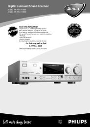
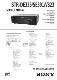
CONNECTIONS<br />
Before attempting to make any connections to or from this unit, be sure to first switch OFF the power to this unit and to any other<br />
components to which connections are being made.<br />
When making connections between this unit and other components, be sure all connections are made correctly, that is to say L<br />
(left) to L, R (right) to R, “+” to “+” and “–” to “–”. Also, refer to the owner’s manual for each component to be connected to this<br />
unit.<br />
<br />
Compact disc player Tuner Tape deck 1 Tape deck 2<br />
Speakers A<br />
Right<br />
Left<br />
(General model)<br />
To AC outlet<br />
Right<br />
Left<br />
Turntable<br />
Video cassette<br />
player, LD player,<br />
etc.<br />
Tape deck 3<br />
Speakers B<br />
* : Refer to “ABOUT THE ACCESSORY TERMINALS” on page 6.<br />
4
English<br />
<br />
Tuner Compact disc player Tape deck 1 Tape deck 2<br />
Speakers A<br />
Right<br />
Left<br />
(General model)<br />
To AC outlet<br />
Turntable<br />
Video cassette<br />
player, LD player,<br />
etc.<br />
Right<br />
Speakers B<br />
Left<br />
* : Refer to “ABOUT THE ACCESSORY TERMINALS” on page 6.<br />
5
CONNECTING SPEAKERS<br />
Connect the SPEAKERS terminals to your speakers with wire<br />
of the proper gauge, cut as short as possible. If the<br />
connections are faulty, no sound will be heard from the<br />
speakers. Make sure that the polarity of the speaker wires is<br />
correct, that is, + and – markings are observed. If these wires<br />
are reversed, the sound will be unnatural and will lack bass.<br />
Do not let the bare speaker wires touch each other and do<br />
not let them touch the metal parts of this unit as this could<br />
damage this unit and/or speakers.<br />
●<br />
●<br />
●<br />
One or two speaker systems can be connected to this unit.<br />
If you connect only one speaker system, connect it to either<br />
the SPEAKERS A or B terminals.<br />
Use speakers with the specified impedance shown on the<br />
rear of this unit.<br />
Banana Plug connections are also possible (except for<br />
Scandinavian models). Simply insert the Banana Plug<br />
connector into the corresponding terminal.<br />
How to Connect:<br />
Red: positive (+)<br />
Black: negative (–)<br />
➁<br />
➀<br />
➂<br />
➀ Unscrew the knob.<br />
➁ Insert the bare wire.<br />
[Remove approx. 5mm<br />
(1/4”) insulation from<br />
the speaker wires.]<br />
➂ Tighten the knob and<br />
secure the wire.<br />
ABOUT THE ACCESSORY TERMINALS<br />
AC OUTLETS (SWITCHED)<br />
(Europe and General models) ............3 SWITCHED OUTLETS<br />
(Australia and U.K. models) ..................1 SWITCHED OUTLET<br />
Use these to connect the power cords from your components<br />
to this unit.<br />
The power to the SWITCHED outlets is controlled by this unit’s<br />
POWER switch or the provided remote control transmitter’s<br />
POWER key. These outlets will supply power to any<br />
component whenever this unit is turned on.<br />
The maximum power (total power consumption of<br />
components) that can be connected to the SWITCHED AC<br />
OUTLETS is 200 watts.<br />
PRE OUT/MAIN IN terminals<br />
Removing the jumper pins enables this unit to independently<br />
perform the functions of a control amplifier and a power<br />
amplifier. These terminals are for connection of a signalprocessing<br />
system such as a graphic equalizer or sound<br />
processor.<br />
If a sound processor or other component is connected, the<br />
VOLUME control of this unit can be used for overall<br />
adjustment of the level of sound. To connect such a unit,<br />
remove the jumper pins from the PRE OUT/MAIN IN terminals,<br />
connect the inputs of that unit to the PRE OUT terminals and<br />
its outputs to the MAIN IN terminals. For details, refer to the<br />
owner’s manual included with the unit to be connected.<br />
REMOTE CONTROL (PHONO) connector<br />
If you have a YAMAHA turntable with a terminal for remote<br />
control, connect it to this connector by using the cable provided<br />
with the turntable. This connection allows you to control the<br />
turntable from the provided remote control transmitter.<br />
GND terminal (For turntable use)<br />
Connecting the ground wire of the turntable to this terminal will<br />
normally minimize hum, but in some cases better results may<br />
be obtained with the ground wire disconnected.<br />
6
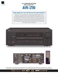
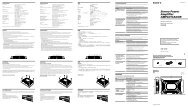
Illustration: <strong>AX</strong>-1070<br />
Parts in shaded area ( )<br />
are not present on <strong>AX</strong>-870.<br />
OPERATIONS<br />
2 3 1,6<br />
English<br />
TO PLAY A SOURCE<br />
PHONES<br />
4 7<br />
PHONO<br />
1<br />
4 Select the speakers to be used.<br />
SPEAKERS<br />
2<br />
Set to the “ ∞ ” position.<br />
POWER<br />
* If you use two speaker systems, press both the A and B<br />
switches.<br />
5 Play the source.<br />
6<br />
3 Select a desired input source.<br />
<br />
<br />
3<br />
Adjust to the desired output level.<br />
* If you select turntable as an input source (PHONO<br />
position), refer to “Setting the PHONO switch” on page 11.<br />
7 If desired, adjust the BASS, TREBLE, BALANCE and<br />
LOUDNESS controls, etc. (Refer to page 10–11.)<br />
7
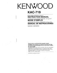
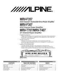
Illustration: <strong>AX</strong>-1070<br />
Parts in shaded area ( )<br />
are not present on <strong>AX</strong>-870.<br />
3,5 3<br />
TO RECORD A SOURCE TO TAPE (OR DUB FROM A TAPE TO ANOTHER)<br />
1<br />
1 Select the source to be recorded.<br />
4 Set the tape deck in the recording mode.<br />
<br />
AUX<br />
REC OUT<br />
CD<br />
1 2/3<br />
TUNER<br />
TAPE COPY<br />
3 1/2<br />
PHONO<br />
<br />
REC OUT<br />
CD TUNER<br />
TAPE COPY 1 2<br />
2 1<br />
PHONO<br />
AUX<br />
5 To monitor the sound being recorded, select the tape<br />
deck being used for recording with the INPUT selector.<br />
<br />
<br />
2 Play the source.<br />
3<br />
3 Confirm the source by selecting it with the INPUT<br />
selector and turning up the VOLUME control.<br />
<br />
<br />
Notes<br />
● If you want to enjoy another source while recording, select it<br />
with the INPUT selector.<br />
● VOLUME, BASS, TREBLE, BALANCE, LOUDNESS<br />
controls and PURE DIRECT switch settings have no effect<br />
on the material being recorded.<br />
3<br />
8
REC OUT selector setting on tape dubbing<br />
<br />
<br />
English<br />
To dub from tape deck 1 to<br />
tape deck 2 or 3 (or both<br />
tape deck 2 and 3 at the<br />
same time)<br />
AUX<br />
REC OUT<br />
CD<br />
1 2/3<br />
TUNER<br />
TAPE COPY<br />
3 1/2<br />
PHONO<br />
To dub from tape deck 1 to<br />
tape deck 2<br />
TAPE COPY 1 2<br />
2 1<br />
AUX<br />
REC OUT<br />
CD TUNER<br />
PHONO<br />
To dub from tape deck 3 to<br />
tape deck 1 or 2 (or both<br />
tape deck 1 and 2 at the<br />
same time)<br />
AUX<br />
REC OUT<br />
CD<br />
1 2/3<br />
TUNER<br />
TAPE COPY<br />
3 1/2<br />
PHONO<br />
To dub from tape deck 2 to<br />
tape deck 1<br />
TAPE COPY 1 2<br />
2 1<br />
AUX<br />
REC OUT<br />
CD TUNER<br />
PHONO<br />
* Tape dubbing cannot be done from tape deck 2 to tape deck<br />
1 or 3.<br />
OPEN/CLOSE THE CONTROL DOOR<br />
When it is not necessary to operate controls inside the control door, close the door.<br />
To close the door<br />
To open the door<br />
9
Adjusting the BALANCE control<br />
Adjust the balance of the output volume to the left and right<br />
speakers to compensate for sound imbalance caused from<br />
speaker location or listening room conditions.<br />
Selecting the SPEAKER system<br />
Because one or two speaker systems can be connected to this<br />
unit, the SPEAKERS switches allow you to select speaker<br />
system A or B, or both at once.<br />
BALANCE<br />
0<br />
l<br />
l<br />
2<br />
3<br />
4<br />
L 5 5 R<br />
2<br />
3<br />
4<br />
SPEAKERS<br />
BASS<br />
Adjusting the BASS and TREBLE<br />
controls<br />
: Turn this clockwise to increase (or counterclockwise<br />
to decrease) the low frequency<br />
response.<br />
TREBLE : Turn this clockwise to increase (or counterclockwise<br />
to decrease) the high frequency<br />
response.<br />
Adjusting the continuously variable<br />
LOUDNESS control<br />
This control provides compensation for the human ears’ loss of<br />
sensitivity to high and low-frequency ranges at low volume.<br />
This control is adjustable to retain full tonal range at any<br />
volume level.<br />
1<br />
LOUDNESS<br />
0<br />
9<br />
Set to the “FLAT” position.<br />
BASS<br />
DEFEAT<br />
l<br />
l<br />
2<br />
2<br />
TREBLE<br />
DEFEAT<br />
l<br />
6<br />
l<br />
2<br />
2<br />
8<br />
7<br />
3<br />
4<br />
5 5<br />
3<br />
4<br />
3<br />
4<br />
5 5<br />
3<br />
4<br />
2<br />
TURNOVER FREQUENCY switch <br />
These switches can be used to adjust the turnover point of the<br />
tone controls: either 200 Hz or 400 Hz for BASS and either 2.5<br />
kHz or 5 kHz for TREBLE. This gives you flexible control over<br />
bass and treble response characteristics.<br />
Set to the loudest listening level that<br />
you would listen to.<br />
TURNOVER FREQUENCY<br />
400Hz<br />
2.5kHz<br />
3<br />
LOUDNESS<br />
200Hz<br />
5kHz<br />
6<br />
0<br />
9<br />
8<br />
7<br />
Turn so that the desired volume can<br />
be achieved.<br />
10
Using the PURE DIRECT switch<br />
Setting the PHONO switch<br />
English<br />
You can enjoy the purest possible sound from your audio<br />
sources by setting this switch so that the indicator illuminates.<br />
By doing so, the audio signal bypasses the BASS, TREBLE,<br />
BALANCE and LOUDNESS controls, the SUBSONIC FILTER<br />
switch and the PRE OUT/MAIN IN terminals, eliminating any<br />
alterations to the audio signal.<br />
Select either MM or MC position depending on your PHONO<br />
cartridge, Moving Mag<strong>net</strong> or Moving Coil type. However, if you<br />
use a high output MC cartridge, select MM position.<br />
PHONO<br />
MC<br />
PURE<br />
DIRECT<br />
MM<br />
Setting the SUBSONIC FILTER switch<br />
If you set this switch to “ON” position, undesirable ultra-lowfrequency<br />
signals caused by turntable rumble or warped<br />
records can be cut out without losing sound quality.<br />
Setting the MODE switch<br />
<br />
This switch can be used for switching between stereo and<br />
monaural operation. Normally this switch should be set to the<br />
STEREO position.<br />
SUBSONIC<br />
FILTER<br />
ON<br />
OFF<br />
MODE<br />
MONO<br />
STEREO<br />
When you listen with headphones<br />
Connect the headphones to the PHONES jack. When listening<br />
with headphones privately, set both the SPEAKERS A and B<br />
switches to the OFF position.<br />
PHONES<br />
11
REMOTE CONTROL TRANSMITTER<br />
The remote control transmitter provided with this unit is designed to control all the most commonly used functions of the unit. If the<br />
CD player, tuner, turntable, equalizer, and tape deck connected to this unit are YAMAHA components, then this remote control<br />
transmitter will also control various functions of each component.<br />
KEY FUNCTIONS<br />
For Control of This Unit<br />
Turns the power on/off.<br />
Selects input source.<br />
When pressed, mutes the volume<br />
level. To resume original volume<br />
level, press this again.<br />
While muting, the indicator on the<br />
VOLUME control flashes on and off<br />
continuously.<br />
Turns the volume level up/down.<br />
For Other Component Control<br />
Identify the remote control transmitter keys with your component’s keys. If these keys are identical, their function will be the<br />
same. On each key function, refer to the corresponding instruction on your component’s manual.<br />
Starts/stops record play on turntable.<br />
Controls tuner<br />
+: Selects higher preset station<br />
number.<br />
–: Selects lower preset station<br />
number.<br />
A/B/C/D/E: Selects the page (A – E)<br />
of preset station buttons.<br />
Controls tape deck.<br />
* DIR A, B and DECK A/B are<br />
applicable only to double cassette<br />
tape deck.<br />
* For a single cassette deck with<br />
automatic reverse function,<br />
pressing DIR A will reverse the<br />
direction of tape running.<br />
Controls compact disc player.<br />
* DISC SKIP is applicable only to<br />
compact disc changer.<br />
Controls equalizer.<br />
* PRESET selects any preset<br />
equalizer curve whenever this is<br />
pressed. (After the last preset curve<br />
is selected, it returns to the first one<br />
by another press on this key.)<br />
Illustration: <strong>AX</strong>-1070<br />
Parts in shaded area (<br />
) are not present on <strong>AX</strong>-870.<br />
12
STANDBY mode (For Europe model only)<br />
While the power is on, pressing the POWER key on the remote<br />
control transmitter switches the unit to the STANDBY mode.<br />
(In this mode, the indicator is half illuminated.)<br />
English<br />
Note<br />
To turn the power off completely, disconnect the AC<br />
power plug from the wall outlet.<br />
POWER on mode<br />
STANDBY mode<br />
NOTES ABOUT THE REMOTE CONTROL TRANSMITTER<br />
Battery installation<br />
1<br />
Remote control transmitter operation range<br />
3<br />
2<br />
Remote control<br />
sensor<br />
Battery replacement<br />
If you find that the remote control transmitter must be used<br />
closer to the main unit, the batteries are weak. Replace both<br />
batteries with new ones.<br />
Notes<br />
● Use only AA, R6, UM-3 batteries for replacement.<br />
● Be sure the polarities are correct. (See the illustration inside<br />
the battery compartment.)<br />
● Remove the batteries if the remote control transmitter will<br />
not be used for an extended period of time.<br />
● If batteries leak, dispose of them immediately. Avoid<br />
touching the leaked material or letting it come in contact with<br />
clothing, etc. Clean the battery compartment thoroughly<br />
before installing new batteries.<br />
30°<br />
30°<br />
Within approximately<br />
7 m (23 feet)<br />
Notes<br />
● There should be no large obstacles between the remote<br />
control transmitter and the main unit.<br />
● If the remote control sensor is directly illuminated by strong<br />
lighting (especially an inverter type of fluorescent lamp etc.),<br />
it might cause the remote control transmitter not to work<br />
correctly. In this case, reposition the main unit to avoid<br />
direct lighting.<br />
13
TROUBLESHOOTING<br />
If the unit fails to operate normally, check the following points to determine whether the fault can be corrected by the simple<br />
measures suggested. If it cannot be corrected, or if the fault is not listed in the SYMPTOM column, disconnect the power cord and<br />
contact your authorized YAMAHA dealer or service center for help.<br />
SYMPTOM<br />
The unit fails to turn on when the POWER<br />
switch is pressed.<br />
No sound.<br />
The sound suddenly goes off.<br />
Only one side speaker outputs the sound.<br />
There is a lack of bass, and no ambience.<br />
Sound “hums”.<br />
CAUSE<br />
Power cord is not plugged in or is not<br />
completely inserted.<br />
Incorrect output cord connections.<br />
Appropriate input source is not selected.<br />
Speaker connections are not secure.<br />
The protection circuit has activated because<br />
of short circuit etc.<br />
Incorrect setting of the BALANCE control.<br />
Incorrect cord connections.<br />
The + and – wires are connected in reverse<br />
at the amplifier or speakers.<br />
Incorrect cord connections.<br />
REMEDY<br />
Firmly plug in the power cord.<br />
Connect the cords properly. If the problem<br />
persists, the cords may be defective.<br />
Select an appropriate input source with the<br />
INPUT selector.<br />
Secure the connections.<br />
Turning the unit off and then on will reset the<br />
protection circuit.<br />
Adjust it to the appropriate position.<br />
Connect the cords properly. If the problem<br />
persists, the cords may be defective.<br />
Connect the speaker wires in the correct<br />
phase (+ and –).<br />
Firmly connect the audio plugs. If the<br />
problem persists, the cords may be defective.<br />
Sound level is low.<br />
Using the BASS, TREBLE, BALANCE,<br />
LOUDNESS controls and SUBSONIC<br />
FILTER switch does not affect the tone.<br />
The remote control transmitter does not<br />
work.<br />
The distance or range within which the<br />
remote control transmitter can be used<br />
decreases.<br />
No connection from the turntable to the GND<br />
terminal.<br />
The LOUDNESS control is functioning.<br />
The MUTING switch is ON.<br />
The PURE DIRECT switch is ON.<br />
Direct sunlight or lighting (of an inverter type<br />
of flourescent lamp etc.) is striking the<br />
remote control sensor of the main unit.<br />
The batteries of this remote control<br />
transmitter are too weak.<br />
Make the GND connection between the<br />
turntable and this unit.<br />
Set the LOUDNESS control to the FLAT<br />
position.<br />
First, turn the volume control to the full left.<br />
Then, turn the MUTING switch OFF with the<br />
remote control transmitter and adjust the<br />
volume.<br />
The PURE DIRECT switch must be switched<br />
OFF to use those controls.<br />
Change position of the main unit.<br />
Replace the batteries with new ones.<br />
14
SPECIFICATIONS<br />
Minimum RMS Output Power per Channel<br />
<br />
8 ohms, 20 Hz to 20 kHz, 0.01% THD<br />
...............................................145W+145W<br />
6 ohms, 20 Hz to 20 kHz, 0.02% THD<br />
...............................................185W+185W<br />
<br />
8 ohms, 20 Hz to 20 kHz, 0.015% THD<br />
...............................................110W+110W<br />
6 ohms, 20 Hz to 20 kHz, 0.03% THD<br />
...............................................130W+130W<br />
Dynamic Power per Channel<br />
(by IHF Dynamic Headroom measuring<br />
method)<br />
<br />
8/6/4/2 ohms.................220/290/360/460W<br />
<br />
8/6/4/2 ohms.................150/200/250/330W<br />
DIN Standard Output Power per Channel<br />
[Europe model only]<br />
<br />
(4 ohms, 1 kHz, 0.7% THD) ..............250W<br />
<br />
(4 ohms, 1 kHz, 0.7% THD) ..............185W<br />
Dynamic Headroom [General model only]<br />
<br />
8/6 ohms ...........................1.81 dB/1.95 dB<br />
<br />
8/6 ohms ...........................1.35 dB/0.97 dB<br />
IEC Power (8 ohms, 1 kHz, 0.01% THD)<br />
[Europe model only]<br />
.......................................170W<br />
.........................................125W<br />
Power Band Width<br />
<br />
8 ohms, 72.5W, 0.03% THD<br />
..........................................10 Hz to 50 kHz<br />
<br />
8 ohms, 55W, 0.03% THD<br />
..........................................10 Hz to 50 kHz<br />
Damping Factor<br />
8 ohms, 20 Hz–20 kHz<br />
................................350 or more<br />
..................................320 or more<br />
Input Sensitivity/Impedance<br />
PHONO MM.....................2.5 mV/47 k-ohms<br />
PHONO MC ......................160 µV/220 ohms<br />
CD/TUNER/TAPE/AUX<br />
........................................150 mV/47 k-ohms<br />
MAIN IN<br />
..........................1.0V/47 k-ohms<br />
............................0.9V/47 k-ohms<br />
Maximum Input Signal (1 kHz, 0.01% THD)<br />
<br />
PHONO MM......................................170 mV<br />
PHONO MC .....................................13.5 mV<br />
<br />
PHONO MM......................................160 mV<br />
PHONO MC .....................................12.5 mV<br />
Output Level/Impedance<br />
<br />
REC OUT ....................150 mV/2.2 k-ohms<br />
PRE OUT..........................1.0V/1.8 k-ohms<br />
<br />
REC OUT ....................150 mV/2.2 k-ohms<br />
PRE OUT..........................1.0V/1.6 k-ohms<br />
Maximum Voltage Output<br />
<br />
20 Hz to 20 kHz, 0.02% THD ..............6.5V<br />
<br />
20 Hz to 20 kHz, 0.01% THD ..............1.4V<br />
Headphone Jack Rated Output/ Impedance<br />
Output Level (8 ohms, 1 kHz, 0.015% THD)<br />
..........................................1.05V<br />
..............................................0.5V<br />
Impedance<br />
...................................220 ohms<br />
.....................................470 ohms<br />
Frequency Response (20 Hz to 20 kHz)<br />
CD/TUNER/TAPE/AUX ....................0±0.5 dB<br />
MAIN IN...........................................0±0.5 dB<br />
RIAA Equalization Deviation (20 Hz to 20 kHz)<br />
PHONO MM......................................±0.3 dB<br />
PHONO MC ......................................±0.5 dB<br />
Total Harmonic Distortion (20 Hz to 20 kHz)<br />
<br />
PHONO MM to REC OUT (3V) ......0.003%<br />
PHONO MC to REC OUT (3V).......0.007%<br />
CD/TUNER/TAPE/AUX to PRE OUT (1V)<br />
........................................................0.004%<br />
CD/TUNER/TAPE/AUX to SP OUT<br />
(72.5W/8 ohms)..............................0.007%<br />
MAIN IN to SP OUT<br />
(72.5W/8 ohms)..............................0.005%<br />
<br />
PHONO MM to REC OUT (3V) ......0.003%<br />
PHONO MC to REC OUT (3V).......0.007%<br />
CD/TUNER/TAPE/AUX to PRE OUT (1V)<br />
........................................................0.005%<br />
CD/TUNER/TAPE/AUX to SP OUT<br />
(55W/8 ohms).................................0.008%<br />
MAIN IN to SP OUT<br />
(55W/8 ohms).................................0.006%<br />
Signal-to-Noise Ratio (IHF-A Network)<br />
PHONO MM (5 mV Input Shorted)<br />
............................................................ 92 dB<br />
PHONO MC (500 µV Input Shorted)<br />
............................................................ 75 dB<br />
CD/TUNER/TAPE/AUX (Input Shorted)<br />
(PURE DIRECT; ON) ..................... 110 dB<br />
Residual Noise (IHF-A Network)<br />
(PURE DIRECT; ON)<br />
..........................................35 µV<br />
............................................80 µV<br />
Channel Separation (Vol. –30 dB)<br />
PHONO MM/MC (Input Shorted<br />
1 kHz/10 kHz) .........................70 dB/55 dB<br />
CD/TUNER/TAPE/AUX (Input 5.1 k-ohms<br />
Terminated 1 kHz/10 kHz) ......65 dB/50 dB<br />
Tone Control Characteristics<br />
BASS:<br />
Boost/cut ............................±10 dB (20 Hz)<br />
Turnover Frequency<br />
...........................200, 400 Hz<br />
.....................................350 Hz<br />
TREBLE:<br />
Boost/cut...........................±10 dB (20 kHz)<br />
Turnover Frequency<br />
..............................2.5, 5 kHz<br />
....................................3.5 kHz<br />
Filter Characteristics<br />
SUBSONIC FILTER .........15 Hz, –18 dB/oct<br />
Continuous Loudness Control<br />
(Level related equalization)<br />
Attenuation<br />
........................–40 dB (1 kHz)<br />
..........................–30 dB (1 kHz)<br />
Audio Muting .............–20 dB<br />
Gain Tracking Error (0 to –60 dB) ............2 dB<br />
Power Supply<br />
[Australia and U.K. models]<br />
..........................................AC 240V, 50 Hz<br />
[Europe model]..................AC 230V, 50 Hz<br />
[General model]<br />
................AC 110/120/220/240V, 50/60 Hz<br />
Power Consumption<br />
..........................................370W<br />
............................................270W<br />
AC Outlets<br />
[Europe and General models]<br />
3 SWITCHED OUTLETS<br />
..........................................200W max. total<br />
[Australia and U.K. models]<br />
1 SWITCHED OUTLET<br />
..........................................200W max. total<br />
Dimensions (W x H x D)<br />
......................................435 x 171 x 448 mm<br />
(17-1/8” x 6-3/4” x 17-5/8”)<br />
Weight<br />
................18.3 kg (40 lbs. 4 oz.)<br />
................14.0 kg (30 lbs. 13 oz.)<br />
Accessories ...........Remote control transmitter<br />
Batteries<br />
Specifications subject to change without<br />
notice.<br />
English<br />
15
YAMAHA ELECTRONICS CORPORATION, USA 6660 ORANGETHORPE AVE., BUENA PARK, CALIF. 90620, U.S.A.<br />
YAMAHA CANADA MUSIC LTD. 135 MILNER AVE., SCARBOROUGH, ONTARIO M1S 3R1, CANADA<br />
YAMAHA ELECTRONIK EUROPA G.m.b.H. SIEMENSSTR. 22-34, D-25462 RELLINGEN BEI HAMBURG, F.R. OF GERMANY<br />
YAMAHA ELECTRONIQUE FRANCE S.A. RUE AMBROISE CROIZAT BP70 CROISSY-BEAUBOURG 77312 MARNE-LA-VALLEE CEDEX02, FRANCE<br />
YAMAHA ELECTRONICS (UK) LTD. YAMAHA HOUSE, 200 RICKMANSWORTH ROAD WATFORD, HERTS WD1 7JS, ENGLAND<br />
YAMAHA SCANDINAVIA A.B. J A WETTERGRENS GATA 1, BOX 30053, 400 43 VÄSTRA FRÖLUNDA, SWEDEN<br />
YAMAHA MUSIC AUSTRALIA PTY, LTD. 17-33 MARKET ST., SOUTH MELBOURNE, 3205 VIC., AUSTRALIA 0000000