JBL CS60-4.pdf - Hifi-pictures.net
JBL CS60-4.pdf - Hifi-pictures.net
JBL CS60-4.pdf - Hifi-pictures.net

You also want an ePaper? Increase the reach of your titles
YUMPU automatically turns print PDFs into web optimized ePapers that Google loves.
CS300.1<br />
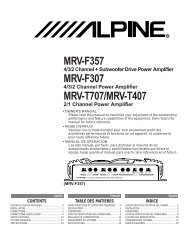
<strong>CS60</strong>.4<br />
<strong>CS60</strong>.2<br />
CAR AUDIO<br />
POWER AMPLIFIER<br />
OWNER’S MANUAL<br />
www.jbl.com<br />
The Official Brand of Live Music.
INSTALLATION<br />
THANK YOU<br />
for purchasing a <strong>JBL</strong> CS Series amplifier.<br />
In order that we may better serve you<br />
should you require warranty service for<br />
your new amplifier, please retain your<br />
original purchase receipt and register your<br />
new <strong>JBL</strong> amplifier online at www.jbl.com.<br />
WARNING<br />
Playing loud music in an automobile<br />
can hinder your ability to hear traffic and<br />
permanently damage your hearing. We<br />
recommend listening at low or moderate<br />
levels while driving your car. <strong>JBL</strong> accepts<br />
no liability for hearing loss, bodily injury or<br />
property damage resulting from the use or<br />
misuse of this product.<br />
IMPORTANT<br />
To get the best performance from your<br />
<strong>JBL</strong> CS Series amplifiers, we strongly<br />
recommend that installation be entrusted<br />
to a qualified professional. Although<br />
these instructions explain how to install<br />
CS amplifiers in a general sense, they do<br />
not show specific installation methods<br />
that may be required for your particular<br />
vehicle. If you do not have the necessary<br />
tools or experience, do not attempt the<br />
installation yourself. Instead, please ask<br />
your authorized <strong>JBL</strong> car audio dealer<br />
about professional installation.<br />
INSTALLATION<br />
WARNINGS AND TIPS<br />
• Always wear protective eyewear when<br />
using tools.<br />
• Turn off the audio system and other<br />
electrical devices before you start.<br />
Disconnect the (–) negative lead from<br />
your vehicle’s battery.<br />
• At the installation sites, locate and<br />
make a note of all fuel lines, hydraulic<br />
brake lines, vacuum lines and electrical<br />
wiring. Use extreme caution when cutting<br />
or drilling in and around these areas.<br />
• Check clearances on both sides of<br />
a planned mounting surface before<br />
drilling any holes or installing any<br />
screws. Remember that the screws<br />
can extend behind the surface.<br />
• Before drilling or cutting holes, use a<br />
utility knife to remove unwanted fabric<br />
or vinyl to keep material from snagging<br />
in a drill bit.<br />
• When routing cables, keep input-signal<br />
cables away from power cables and<br />
speaker wires.<br />
• When making connections, make<br />
certain they are secure and properly<br />
insulated.<br />
• If the amplifier’s fuse must be replaced,<br />
use only the same type and rating as<br />
that of the original. Do not substitute<br />
another kind.<br />
CHOOSING A LOCATION<br />
AND MOUNTING THE<br />
AMPLIFIER<br />
Choose a mounting location in the trunk<br />
or cargo area where the amplifier will not<br />
be damaged by shifting cargo. Amplifier<br />
cooling is essential for proper amplifier<br />
operation. If the amplifier is to be installed<br />
in an enclosed space, make sure there is<br />
sufficient air circulation for the amplifier<br />
to cool itself.<br />
When mounting the amplifier under a<br />
seat, ensure that it is clear of all moving<br />
seat parts and does not affect the seat<br />
adjustments. Mount the amplifier so it<br />
is not damaged by the feet of backseat<br />
passengers. Make sure that the amplifier<br />
is mounted securely using nuts and bolts<br />
or the supplied mounting screws.<br />
Mount the amplifier so that it remains<br />
dry – never mount an amplifier outside<br />
the vehicle or in the engine compartment.<br />
2
INSTALLATION<br />
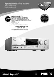
POWER CONNECTIONS<br />
The CS amplifiers require a reliable<br />
connection to the vehicle’s electrical<br />
system in order to perform optimally.<br />
See Figures 1, 2 and 3 for terminal<br />
connection locations. Please adhere<br />
to the following instructions carefully:<br />
Ground Connection<br />
Connect the amplifier’s Ground (GND)<br />
terminal to a solid point on the vehicle’s<br />
metal chassis, as close to the amplifier<br />
as possible. Refer to the wire gauge chart to<br />
determine minimum wire gauge size. Sand<br />
away any paint from this location; use a startype-lock<br />
washer to secure the connection.<br />
Power Connection<br />
Connect a wire (see chart at right for<br />
appropriate gauge) directly to the vehicle’s<br />
positive battery terminal, and install an<br />
appropriate fuse holder within 18" of the<br />
battery terminal. Do not install the fuse at<br />
this time. Route the wire to the amplifier’s<br />
location, and connect it to the amplifier’s<br />
Positive (+12V) terminal. Be sure to use<br />
appropriate grommets whenever routing<br />
wires through the firewall or other sheet<br />
metal. Failure to adequately protect the<br />
positive wire from potential damage may<br />
result in a vehicle fire. When you are done<br />
routing and connecting this wire, you may<br />
install the fuse at the battery.<br />
Remote Connection<br />
Connect the amplifier’s Remote (REM)<br />
terminal to the source unit’s Remote Turn-<br />
On lead using a minimum of 18-gauge wire.<br />
NOTE: If your source unit does not have a<br />
remote turn-on connection, connect the<br />
amplifier’s (REM) terminal to the vehicle’s<br />
accessory circuit.<br />
Speaker Connections<br />
Refer to the application guides on the<br />
pages that follow. Speaker connections<br />
should be made using a minimum of<br />
16-gauge wire.<br />
Wire Gauge Chart<br />
Amplifier Maximum Minimum<br />
Model Current Draw Wire Gauge<br />
<strong>CS60</strong>.2 22A #8 AWG<br />
<strong>CS60</strong>.4 40A #8 AWG<br />
CS300.1 42A #8 AWG<br />
These recommendations assume 10' – 12'<br />
wire runs. If your installation differs markedly,<br />
you will need to adjust the wire gauge<br />
accordingly.<br />
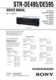
Figure 1. Terminal connection end plate for CS300.1.<br />
Figure 2. Terminal connection end plate for <strong>CS60</strong>.4.<br />
Figure 3. Terminal connection end plate for <strong>CS60</strong>.2.<br />
3
APPLICATIONS – CS300.1<br />
The CS subwoofer amplifier is a<br />
single-channel amplifier. There are<br />
two sets of terminals to make it easy<br />
to connect multiple woofers. Either<br />
set of (+/–) terminals may be used<br />
when connecting woofers.<br />
To the right are two application<br />
diagrams to help plan your subwoofer<br />
system installation. Figures 4 and 5<br />
show how to configure the CS300.1<br />
subwoofer amplifier.<br />
Figure 4. CS subwoofer amplifier<br />
with two woofers connected.<br />
NOTE: For simplicity, Figures 4 and 5<br />
do not show power, remote and input<br />
connections.<br />
NOTE: Minimum speaker load is<br />
2 ohms total.<br />
Figure 5. CS subwoofer amplifier<br />
with one woofer connected.<br />
4
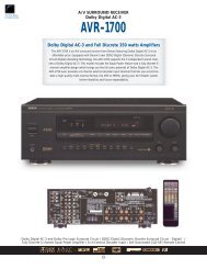
APPLICATIONS – <strong>CS60</strong>.4<br />
The <strong>CS60</strong>.4 can be set up for stereo<br />
4-channel, 3-channel or bridged<br />
2-channel operation, as shown in<br />
Figures 6 through 8.<br />
Front Left<br />
Front Right<br />
NOTE: For simplicity, Figures 6 through<br />
8 do not show power, remote and input<br />
connections.<br />
Figure 6. <strong>CS60</strong>.4 amplifier in 4-channel (stereo)<br />
operation to drive front and rear full-range speakers.<br />
Rear Left<br />
Rear Right<br />
NOTE: Minimum speaker impedance<br />
for stereo operation is 2 ohms.<br />
Minimum speaker impedance for<br />
bridged operation is 4 ohms.<br />
Front Left<br />
Front Right<br />
Rear Left<br />
Rear Right<br />
Front Left<br />
Front Right<br />
Figure 7. <strong>CS60</strong>.4 is set up for 3-channel operation<br />
to drive a set of full-range speakers and a subwoofer.<br />
Figure 8. <strong>CS60</strong>.4 used in bridged 2-channel mode to<br />
drive a set of components or subwoofers. Set crossovers<br />
according to application.<br />
5
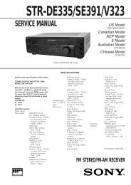
APPLICATIONS – <strong>CS60</strong>.2<br />
Figure 9. <strong>CS60</strong>.2 used in 2-channel (stereo)<br />
Left<br />
Right<br />
operation to drive a set of full-range speakers.<br />
Left<br />
Right<br />
Figure 10. <strong>CS60</strong>.2 used in bridge mode to drive a<br />
subwoofer.<br />
6
CONTROLS AND SETUP<br />
TROUBLESHOOTING<br />
SETTING THE<br />
CROSSOVER(S)<br />
Determine your system plans and set<br />
the crossover mode switch accordingly.<br />
If your system design does not include<br />
a subwoofer with the <strong>CS60</strong>.4, set the<br />
crossover mode to FLAT and skip to<br />
“Setting Input Sensitivity.”<br />
Initially set the crossover frequency<br />
control midway. While listening to music,<br />
adjust the crossover for the least<br />
perceived distortion from the speakers,<br />
allowing them to reproduce as much<br />
bass as possible.<br />
Systems using a separate subwoofer set<br />
the crossover mode to HP (high pass) for<br />
your full-range speakers. Adjust the<br />
crossover frequency to limit bass and<br />
provide increased system volume with<br />
less distortion.<br />
For subwoofers, choose the highest<br />
frequency that removes vocal information<br />
from the sound of the subwoofer.<br />
If using the <strong>CS60</strong>.4 or <strong>CS60</strong>.2 to drive a<br />
subwoofer(s), set the crossover mode to<br />
LP (low pass).<br />
SETTING INPUT<br />
SENSITIVITY<br />
1. Initially turn the INPUT LEVEL control(s)<br />
to minimum (counter clockwise).<br />
2. Reconnect the (–) negative lead to the<br />
vehicle’s battery. Apply power to the<br />
audio system and play a dynamic music<br />
track.<br />
3. On the source unit, increase the volume<br />
control to 3/4 volume. Slowly increase<br />
the INPUT LEVEL control(s) toward three<br />
o’clock until you hear slight distortion<br />
in the music. Then reduce the INPUT<br />
LEVEL slightly until distortion is no<br />
longer heard.<br />
NOTE: After the source unit is on, blue<br />
LEDs (on the top panel) will light, indicating<br />
the amplifier is on. If not, check the wiring,<br />
especially the remote connection from the<br />
source unit. Also refer to “Troubleshooting”<br />
guide at right.<br />
SYMPTOM LIKELY CAUSE SOLUTION<br />
No audio No voltage at BATT+ Check voltages at<br />
(POWER LEDs or REM terminals, amplifier terminals<br />
are off) or bad or no ground with VOM<br />
connection<br />
No audio Amplifier is Make sure amplifier<br />
(POWER overheated cooling is not blocked<br />
LEDs are on)<br />
at mounting location;<br />
verify speaker-system<br />
impedance is within<br />
specified limits<br />
Voltage more than 16V Check vehicle<br />
or less than 8.5V on charging system<br />
BATT+ connection<br />
No audio Voltage less than 9V on Check vehicle<br />
(POWER BATT+ connection charging system<br />
LEDs flash)<br />
DC voltage on<br />
Amplifier may need<br />
amplifier output<br />
service; see enclosed<br />
warranty card for<br />
service information<br />
Distorted audio Input sensitivity is Check INPUT<br />
not set properly, or LEVEL setting; or<br />
amplifier or source check speaker wires<br />
unit is defective<br />
for shorts or grounds<br />
Distorted audio Short circuit in Remove speaker leads<br />
and POWER speaker or wire one at a time to locate<br />
LEDs flash<br />
shorted speaker or<br />
wire, then repair<br />
Music lacks Speakers are not Check speaker<br />
“punch” connected properly connections for<br />
proper polarity<br />
7
SPECIFICATIONS<br />
Declaration of Conformity<br />
CS300.1<br />
• 200W RMS x 1 channel at 4 ohms and ≤1% THD + N<br />
• Signal-to-noise ratio: 100dBA (reference 1W into 4 ohms)<br />
• 300W RMS x 1 channel at 2 ohms, 14.4V supply and ≤1% THD + N<br />
• Dynamic power: 460W at 2 ohms<br />
• Effective damping factor: 6.395 at 4 ohms<br />
• Frequency response: 10Hz – 300Hz (–3dB)<br />
• Maximum input signal: 6V<br />
• Maximum sensitivity: 100mV<br />
• Output regulation: – 0.07dB at 4 ohms<br />
• Dimensions (L x W x H): 12-11/16" x 10-1/4" x 2-3/16"<br />
• Fuses: 20A x 2<br />
We, Harman Consumer Group International<br />
2, route de Tours<br />
72500 Chateau du Loir<br />
France<br />
declare in own responsibility that the products<br />
described in this owner’s manual are in compliance<br />
with technical standards:<br />
EN 55013:2001 + A1:2003<br />
EN 55020:2002 + A1:2003<br />
Klaus Lebherz<br />
Harman Consumer Group<br />
International<br />
Chateau du Loir, France 7/05<br />
<strong>CS60</strong>.4<br />
• 60W RMS x 4 channels at 4 ohms and ≤1% THD + N<br />
• Signal-to-noise ratio: 86dBA (reference 1W into 4 ohms)<br />
• 80W RMS x 4 channels at 2 ohms, 14.4V supply and ≤1% THD + N<br />
• 160W RMS x 2 channels at 4 ohms, 14.4V supply and ≤1% THD + N<br />
• Dynamic power: 145W at 2 ohms<br />
• Effective damping factor: 6.395 at 4 ohms<br />
• Frequency response: 10Hz – 27kHz (–3dB)<br />
• Maximum input signal: 6V<br />
• Maximum sensitivity: 100mV<br />
• Output regulation: – 0.03dB at 4 ohms<br />
• Dimensions (L x W x H): 13-1/4" x 10-1/4" x 2-3/16"<br />
• Fuses: 25A x 2<br />
<strong>JBL</strong> Consumer Products<br />
250 Crossways Park Drive<br />
Woodbury, NY 11797 USA<br />
© 2005 Harman International<br />
Industries, Incorporated. All rights reserved.<br />
<strong>JBL</strong> is a trademark of Harman International<br />
Industries, Incorporated, registered in the<br />
United States and/or other countries.<br />
Part No. CSAMPOM7/05<br />
<strong>CS60</strong>.2<br />
• 60W RMS x 2 channels at 4 ohms and ≤1% THD + N<br />
• Signal-to-noise ratio: 86dBA (reference 1W into 4 ohms)<br />
• 80W RMS x 2 channels at 2 ohms, 14.4V supply and ≤1% THD + N<br />
• 160W RMS x 1 channel at 4 ohms, 14.4V supply and ≤1% THD + N<br />
• Dynamic power: 160W at 2 ohms<br />
• Effective damping factor: 6.395 at 4 ohms<br />
• Frequency response: 10Hz – 27kHz (–3dB)<br />
• Maximum input signal: 6V<br />
• Maximum sensitivity: 100mV<br />
• Output regulation: – 0.03dB at 4 ohms<br />
• Dimensions (L x W x H): 8-7/8" x 10-1/4" x 2-1/4"<br />
• Fuses: 25A x 1<br />
This product is intended for mobile applications without connection to the<br />
110/230 volts mains.<br />
Features, specifications and appearance are subject to change without notice.<br />
www.jbl.com