
You also want an ePaper? Increase the reach of your titles
YUMPU automatically turns print PDFs into web optimized ePapers that Google loves.
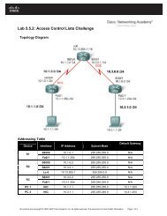
Lab 4.4 Comparing Queuing Strategies<br />
Learning Objectives<br />
Implement FIFO, WFQ, CQ, and PQ queuing strategies<br />
Compare queuing strategies using the NQR tool<br />
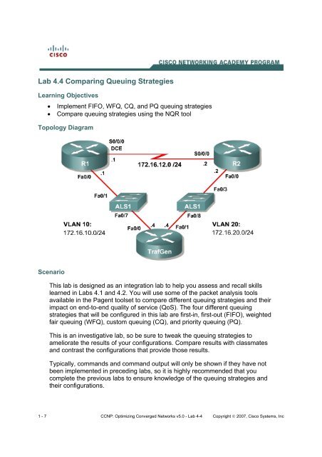
Topology Diagram<br />
Scenario<br />
This lab is designed as an integration lab to help you assess and recall skills<br />
learned in Labs 4.1 and 4.2. You will use some of the packet analysis tools<br />
available in the Pagent toolset to compare different queuing strategies and their<br />
impact on end-to-end quality of service (<strong>QoS</strong>). The four different queuing<br />
strategies that will be configured in this lab are first-in, first-out (FIFO), weighted<br />
fair queuing (WFQ), custom queuing (CQ), and priority queuing (PQ).<br />
This is an investigative lab, so be sure to tweak the queuing strategies to<br />
ameliorate the results of your configurations. Compare results with classmates<br />
and contrast the configurations that provide those results.<br />
Typically, commands and command output will only be shown if they have not<br />
been implemented in preceding labs, so it is highly recommended that you<br />
complete the previous labs to ensure knowledge of the queuing strategies and<br />
their configurations.<br />
1 - 7 CCNP: Optimizing Converged Networks v5.0 - Lab 4-4 Copyright 2007, Cisco Systems, Inc
Preparation<br />
This lab relies on the Basic Pagent Configuration, which you should have<br />
created in Lab 3.1: Preparing for <strong>QoS</strong>.<br />
Prior to beginning this lab, configure R4 and the switch according to the Basic<br />
Pagent Configuration. You may easily accomplish this on R4 by loading the<br />
basic-ios.cfg file from flash memory into the NVRAM, and reloading.<br />
TrafGen# copy flash:basic-ios.cfg startup-config<br />
Destination filename [startup-config]?<br />
[OK]<br />
2875 bytes copied in 1.456 secs (1975 bytes/sec)<br />
TrafGen# reload<br />
Proceed with reload? [confirm]<br />
On the switch, load the basic.cfg file into NVRAM and reload the device.<br />
ALS1# copy flash:basic.cfg startup-config<br />
Destination filename [startup-config]?<br />
[OK]<br />
2875 bytes copied in 1.456 secs (1975 bytes/sec)<br />
ALS1# reload<br />
Proceed with reload? [confirm]<br />
Unlike Labs 4.1 and 4.2, this lab will use the NQR tool in the Pagent toolset<br />
rather than the TGN traffic generator. Do not load the TGN traffic generator<br />
configuration.<br />
In addition, add the Fast Ethernet 0/3 interface on the switch to VLAN 20 since<br />
R2 will be the exit point from the network topology in this lab.<br />
ALS1# configure terminal<br />
ALS1(config)# interface fastethernet 0/3<br />
ALS1(config-if)# switchport access vlan 20<br />
ALS1(config-if)# switchport mode access<br />
Step 1: Configure Addressing and Routing<br />
Configure all IP addresses shown in the topology diagram and use a clock rate<br />
of 800 kbps on the serial link between R1 and R2. Set the informational<br />
bandwidth parameter appropriately on the serial interfaces.<br />
Configure EIGRP AS 1 to include all networks shown in the diagram.<br />
R1(config)# interface fastethernet 0/0<br />
R1(config-if)# ip address 172.16.10.1 255.255.255.0<br />
R1(config-if)# no shutdown<br />
R1(config-if)# interface serial 0/0/0<br />
R1(config-if)# bandwidth 800<br />
R1(config-if)# ip address 172.16.12.1 255.255.255.0<br />
R1(config-if)# clockrate 800000<br />
R1(config-if)# no shutdown<br />
R1(config-if)# router eigrp 1<br />
R1(config-router)# network 172.16.0.0<br />
2 - 7 CCNP: Optimizing Converged Networks v5.0 - Lab 4-4 Copyright 2007, Cisco Systems, Inc
R2(config)# interface fastethernet 0/0<br />
R2(config-if)# ip address 172.16.20.2 255.255.255.0<br />
R2(config-if)# no shutdown<br />
R2(config-if)# interface serial 0/0/0<br />
R2(config-if)# bandwidth 800<br />
R2(config-if)# ip address 172.16.12.2 255.255.255.0<br />
R2(config-if)# no shutdown<br />
R2(config-if)# router eigrp 1<br />
R2(config-router)# network 172.16.0.0<br />
Step 2: Create NQR Configuration for Testing Purposes<br />
Traffic generated from NQR, the traffic generation component of Pagent,<br />
requires almost all header fields to be hardcoded. Since the packets will be<br />
generated over Ethernet, you need to set the destination MAC address of the<br />
packets so that they are not broadcast. Remember that this is only the<br />
destination for the first hop, not the final destination MAC address. Use the<br />
show interfaces command to discover the value of the 48-bit MAC address.<br />
Example:<br />
R1# show interfaces fastethernet0/0<br />
FastEthernet0/0 is up, line protocol is up<br />
Hardware is MV96340 Ethernet, address is 0019.0623.4380 (bia 0019.0623.4380)<br />
<br />
Use the MAC address on R1 as the Layer 2 destination of the NQR stream you<br />
will configure next.<br />
On R4, issue the nqr command in privileged EXEC mode to enter NQR<br />
configuration mode. Then, copy and paste the NQR configuration shown below<br />
into a text editor, such as Notepad, and replace the $R1_MAC$ field with the<br />
MAC address you displayed in the output of the show interfaces fastethernet<br />
0/0 command. Then, copy and paste that configuration into the TrafGen router.<br />
fastethernet0/0<br />
add tcp<br />
send 1000<br />
rate 60<br />
length random 200 to 1000<br />
l2-dest $R1_MAC$<br />
l3-src 172.16.10.4<br />
l3-dest 172.16.20.4<br />
l4-dest 23<br />
fastethernet0/1 capture<br />
add clone-of 1<br />
l4-dest 21<br />
add clone-of 1<br />
l4-dest 119<br />
add clone-of 1<br />
l4-dest 22<br />
add clone-of 1<br />
l4-dest 6000<br />
To begin NQR testing, issue either the start send command in NQR<br />
configuration mode or the nqr start send command from privileged EXEC<br />
3 - 7 CCNP: Optimizing Converged Networks v5.0 - Lab 4-4 Copyright 2007, Cisco Systems, Inc
mode. Time will pass, and then the router will inform you when all packets have<br />
been sent. There is no need to stop the streams since they will stop on their<br />
own.<br />
Finally, issue the show pkt-seq-drop-stats, show delay, and show jitter NQR<br />
commands to display drop/resequencing, delay, and jitter statistics,<br />
respectively. Example output is shown below, although this type of output will<br />
not be shown again later in the lab. Record all statistics by copying and pasting<br />
them into a text editor such as Notepad. Record a baseline reading for your<br />
current topology.<br />
R4(NQR:OFF,Fa0/0:5/5)# start send<br />
R4(NQR:SEND,Fa0/0:5/5)#<br />
Send process complete.<br />
R4(NQR:WAIT,Fa0/0:5/5)#<br />
R4(NQR:OFF,Fa0/0:5/5)# show pkt-seq-drop-stats<br />
Summary of packet sequence/drop stats of traffic streams<br />
ts# template interface sent recvd dropped out-of-seq max-seq<br />
1 TCP Fa0/0.10* 1000 625 375 271 28<br />
2 TCP Fa0/0.10* 1000 637 363 271 30<br />
3 TCP Fa0/0.10* 1000 638 362 254 30<br />
4 TCP Fa0/0.10* 1000 598 402 265 29<br />
5 TCP Fa0/0.10* 1000 604 396 267 28<br />
R4(NQR:OFF,Fa0/0:5/5)# show delay-stats<br />
Summary of delay-stats of traffic streams<br />
ts# template interface min-delay max-delay avg-delay stdev-delay<br />
1 TCP Fa0/0.10* 0.013646 0.433202 0.355633 0.047306<br />
2 TCP Fa0/0.10* 0.012966 0.426203 0.352435 0.048258<br />
3 TCP Fa0/0.10* 0.008824 0.436855 0.357987 0.046055<br />
4 TCP Fa0/0.10* 0.028379 0.448521 0.361942 0.049450<br />
5 TCP Fa0/0.10* 0.015277 0.457674 0.363785 0.046969<br />
R4(NQR:OFF,Fa0/0:5/5)# show jitter-stats<br />
Summary of jitter-stats of traffic streams<br />
ts# template interface min-jitter max-jitter avg-jitter stdev-jitter<br />
1 TCP Fa0/0.10* 0.000063 0.204891 0.033416 0.034363<br />
2 TCP Fa0/0.10* 0.000098 0.190365 0.034329 0.034809<br />
3 TCP Fa0/0.10* 0.000015 0.172803 0.033511 0.032503<br />
4 TCP Fa0/0.10* 0.000047 0.223152 0.035887 0.034892<br />
5 TCP Fa0/0.10* 0.000070 0.165289 0.035484 0.031709<br />
Step 3: Test FIFO Queuing<br />
This lab will compare four different queuing types. The first type is the most<br />
basic, FIFO queuing.<br />
Configure FIFO queuing on the serial interface on R1. Recall that disabling all<br />
other queuing strategies on an interface will enable FIFO queuing.<br />
Notice that the scenario the authors have designed overpowers all of the<br />
queuing mechanisms implemented because there is simply much more traffic<br />
4 - 7 CCNP: Optimizing Converged Networks v5.0 - Lab 4-4 Copyright 2007, Cisco Systems, Inc
than the bandwidth of the serial link. If you had this ratio of legitimate traffic to<br />
bandwidth in a production network, then queuing strategies would not solve the<br />
problem. It would be necessary to obtain additional bandwidth.<br />
Step 4: Test Weighted Fair Queuing<br />
Enable WFQ on the serial interface. Run the NQR streams again using nqr<br />
start send and compare the results of the show commands.<br />
R1(config)# interface serial0/0/0<br />
R1(config-if)# fair-queue<br />
Is there a significant difference between the statistics using WFQ and FIFO in<br />
this scenario?<br />
No.<br />
The streams from NQR are generated in something similar to a round-robin<br />
fashion with the same number of packets for each stream. The result is that<br />
many of the same packets will be forwarded by WFQ as by FIFO, but this is<br />
only by the construction of the streams on TrafGen. In real networks, many<br />
traffic patterns are bursty, unlike this simulation. To understand what is meant<br />
by bursty traffic patterns, think of loading a web page. You type in a URL and<br />
there is a burst of traffic as the text and the graphics load. Then while you read<br />
the web page, there is no additional traffic being sent across the network. Then<br />
you click on a link, and another burst of traffic traverses the network.<br />
What effect does the function of the NQR generator have on your results?<br />
Since the packets are being generated in a round-robin fashion, WFQ and FIFO<br />
perform very similarly so WFQ does not have much of an advantage over FIFO.<br />
Provide a circumstance in which you would expect a different result from FIFO?<br />
If the generated flows were more mixed than in the current scenario, you would<br />
expect lower latency with WFQ than with FIFO.<br />
Step 5: Test Custom Queuing<br />
Configure custom queuing (CQ) on R1’s serial interface. Place each traffic<br />
stream in its own queue but do not customize any parameters of it. (The port<br />
numbers configured for the NQR streams are TCP ports 23, 21, 119, 22, and<br />
6000) Run the NQR streams and compare results as you did before.<br />
5 - 7 CCNP: Optimizing Converged Networks v5.0 - Lab 4-4 Copyright 2007, Cisco Systems, Inc
R1(config)# queue-list 1 protocol ip 1 tcp telnet<br />
R1(config)# queue-list 1 protocol ip 2 tcp ftp<br />
R1(config)# queue-list 1 protocol ip 3 tcp nntp<br />
R1(config)# queue-list 1 protocol ip 4 tcp 22<br />
R1(config)# queue-list 1 default 5<br />
R1(config)# interface serial0/0/0<br />
R1(config-if)# custom-queue-list 1<br />
Contrast the results for the CQ test with those of the previous queuing<br />
strategies.<br />
Delay, jitter, and dropped packets were all worse (higher) than with the other<br />
queuing strategies. Because the queues are services in a round-robin fashion,<br />
delay increases over FIFO and WFQ while packets sit in the queue.<br />
Try making one of the queues have a size of 10000. How does this affect all of<br />
the traffic flows?<br />
R1(config)# queue-list 1 queue 1 byte-count 10000<br />
The affected flow does not lose any packets and has lower jitter and delays<br />
than the other flows. The other ones have more lost packets, as well as having<br />
higher delays and jitter as packets wait for the large queue to reach its byte<br />
count.<br />
Step 6: Test Priority Queuing<br />
Configure priority queuing (PQ) on R1 on the serial interface facing R2. Assign<br />
one of the application protocols in use to the high priority queue, one to the<br />
medium queue, one to the normal queue, and make the low priority queue the<br />
default queue. Run the NQR streams and compare results as you did before.<br />
R1(config)# priority-list 1 protocol ip high tcp telnet<br />
R1(config)# priority-list 1 protocol ip medium tcp ftp<br />
R1(config)# priority-list 1 protocol ip normal tcp 22<br />
R1(config)# priority-list 1 default low<br />
R1(config)# interface serial0/0/0<br />
R1(config-if)# no custom-queue-list 1<br />
R1(config-if)# priority-group 1<br />
How does the packet loss with PQ compare to that of previous queuing<br />
strategies?<br />
The higher priority streams get no packet loss and very low delay and jitter.<br />
There is nearly full loss on the lower priority streams, and high delay and jitter<br />
(when there is enough data for statistics).<br />
6 - 7 CCNP: Optimizing Converged Networks v5.0 - Lab 4-4 Copyright 2007, Cisco Systems, Inc
What would happen if you put all the streams in the high priority queue?<br />
This would effectively make the interface use FIFO queuing.<br />
Final Configurations<br />
R1# show run<br />
!<br />
hostname R1<br />
!<br />
interface FastEthernet0/0<br />
ip address 172.16.10.1 255.255.255.0<br />
no shutdown<br />
!<br />
interface Serial0/0/0<br />
ip address 172.16.12.1 255.255.255.0<br />
priority-group 1<br />
clock rate 800000<br />
no shutdown<br />
!<br />
router eigrp 1<br />
network 172.16.0.0<br />
no auto-summary<br />
!<br />
queue-list 1 protocol ip 1 tcp telnet<br />
queue-list 1 protocol ip 2 tcp ftp<br />
queue-list 1 protocol ip 3 tcp nntp<br />
queue-list 1 protocol ip 4 tcp 22<br />
queue-list 1 default 5<br />
queue-list 1 queue 1 byte-count 10000<br />
priority-list 1 protocol ip high tcp telnet<br />
priority-list 1 protocol ip medium tcp ftp<br />
priority-list 1 protocol ip normal tcp 22<br />
priority-list 1 default low<br />
!<br />
end<br />
R2# show run<br />
!<br />
hostname R2<br />
!<br />
interface FastEthernet0/0<br />
ip address 172.16.20.2 255.255.255.0<br />
no shutdown<br />
!<br />
interface Serial0/0/0<br />
ip address 172.16.12.2 255.255.255.0<br />
no shutdown<br />
!<br />
router eigrp 1<br />
network 172.16.0.0<br />
no auto-summary<br />
!<br />
end<br />
7 - 7 CCNP: Optimizing Converged Networks v5.0 - Lab 4-4 Copyright 2007, Cisco Systems, Inc
Lab 4.5 Class-based Queuing and NBAR<br />
Learning Objectives<br />
Utilize NBAR for protocol detection<br />
Mark IP Precedence<br />
Allocate bandwidth using the Modular <strong>QoS</strong> Command-Line Interface<br />
Configure CBWFQ and LLQ queuing strategies<br />
Topology Diagram<br />
Scenario<br />
In this lab, you will implement classification using Network-based Application<br />
Recognition (NBAR) and the Modular <strong>QoS</strong> CLI (MQC) to configure quality of<br />
service (<strong>QoS</strong>) on R1 and R2. You will configure both class-based marking and<br />
class-based queuing algorithms.<br />
1 - 17 CCNP: Optimizing Converged Networks v5.0 - Lab 4-5 Copyright 2007, Cisco Systems, Inc
Preparation<br />
This lab uses the Basic Pagent Configuration for TrafGen and the switch to<br />
generate and facilitate lab traffic in a stream from TrafGen to R1 to R2. Prior to<br />
beginning this lab, configure TrafGen (R4) and the switch according to the<br />
Basic Pagent Configuration in Lab 3.1: Preparing for <strong>QoS</strong>. You can accomplish<br />
this on R4 by loading the basic-ios.cfg file from flash memory into the NVRAM<br />
and reloading.<br />
TrafGen# copy flash:basic-ios.cfg startup-config<br />
Destination filename [startup-config]?<br />
[OK]<br />
2875 bytes copied in 1.456 secs (1975 bytes/sec)<br />
TrafGen# reload<br />
Proceed with reload? [confirm]<br />
On the switch, load the basic.cfg file into NVRAM and reload the device.<br />
Switch# copy flash:basic.cfg startup-config<br />
Destination filename [startup-config]?<br />
[OK]<br />
2875 bytes copied in 1.456 secs (1975 bytes/sec)<br />
TrafGen# reload<br />
Proceed with reload? [confirm]<br />
On TrafGen, instruct TGN to load the basic-tgn.cfg file and to start generating<br />
traffic.<br />
TrafGen> enable<br />
TrafGen# tgn load-config<br />
TrafGen# tgn start<br />
In addition, add the Fast Ethernet 0/5 interface on the switch to VLAN 20 since<br />
R3 will be the exit point from the network topology in this lab.<br />
Switch# configure terminal<br />
Switch(config)# interface fastethernet 0/5<br />
Switch(config-if)# switchport access vlan 20<br />
Switch(config-if)# switchport mode access<br />
Step 1: Configure the Physical Interfaces<br />
Configure all of the physical interfaces shown in the diagram. Set the clock rate<br />
on the serial link between R1 and R2 to 800000, the clock rate of the serial link<br />
between R2 and R3 to be 128000, and use the no shutdown command on all<br />
interfaces. Set the informational bandwidth parameter on the serial interfaces.<br />
R1(config)# interface fastethernet 0/0<br />
R1(config-if)# ip address 172.16.10.1 255.255.255.0<br />
R1(config-if)# no shutdown<br />
R1(config-if)# interface serial 0/0/0<br />
R1(config-if)# bandwidth 800<br />
R1(config-if)# ip address 172.16.12.1 255.255.255.0<br />
R1(config-if)# clock rate 800000<br />
2 - 17 CCNP: Optimizing Converged Networks v5.0 - Lab 4-5 Copyright 2007, Cisco Systems, Inc
R1(config-if)# no shutdown<br />
R2(config)# interface serial 0/0/0<br />
R2(config-if)# bandwidth 800<br />
R2(config-if)# ip address 172.16.12.2 255.255.255.0<br />
R2(config-if)# no shutdown<br />
R2(config-if)# interface serial 0/0/1<br />
R2(config-if)# bandwidth 128<br />
R2(config-if)# ip address 172.16.23.2 255.255.255.0<br />
R2(config-if)# clock rate 128000<br />
R2(config-if)# no shutdown<br />
R3(config)# interface fastethernet 0/0<br />
R3(config-if)# ip address 172.16.20.3 255.255.255.0<br />
R3(config-if)# no shutdown<br />
R3(config-if)# interface serial 0/0/1<br />
R3(config-if)# bandwidth 128<br />
R3(config-if)# ip address 172.16.23.3 255.255.255.0<br />
R3(config-if)# no shutdown<br />
Issue the show interfaces serial 0/0/0 | include Queueing command on R1 to<br />
verify that the queuing strategy is Weighted Fair Queuing (WFQ).<br />
R1# show interface serial0/0/0 | include Queueing<br />
Queueing strategy: weighted fair<br />
If you see “fifo” as the queuing type, use the interface-level command fairqueue<br />
on the serial interface.<br />
Step 2: Configure EIGRP AS 1<br />
Configure routing between R1, R2 and R3 using Enhanced Interior Gateway<br />
Routing Protocol (EIGRP). Include the entire 172.16.0.0/16 major network in AS<br />
1 and disable automatic summarization.<br />
R1(config)# router eigrp 1<br />
R1(config-router)# no auto-summary<br />
R1(config-router)# network 172.16.0.0<br />
R2(config)# router eigrp 1<br />
R2(config-router)# no auto-summary<br />
R2(config-router)# network 172.16.0.0<br />
R3(config)# router eigrp 1<br />
R3(config-router)# no auto-summary<br />
R3(config-router)# network 172.16.0.0<br />
Verify that the number of packets counted is increasing on the outbound<br />
interface of R3. Use the show interfaces fastethernet 0/1 command. Issue the<br />
command twice to make sure the number of packets output has changed. If the<br />
number is not increasing, troubleshoot Layers 1, 2, and 3 connectivity and the<br />
EIGRP topology.<br />
3 - 17 CCNP: Optimizing Converged Networks v5.0 - Lab 4-5 Copyright 2007, Cisco Systems, Inc
Step 3: Configure NBAR Protocol Discovery<br />
NBAR is an IOS <strong>QoS</strong> feature that allows <strong>QoS</strong> decisions to be made based on<br />
individual protocols. Access control lists (ACLs) can be used to classify traffic<br />
based on headers for Layers 1 through 4 of the OSI model. NBAR, on the other<br />
hand, allows classification based on the upper layers of the OSI model—Layers<br />
4 through 7. Since it does not rely on TCP/UDP port numbers at Layer 4, it can<br />
be used to identify traffic from applications that have dynamic port assignments.<br />
One standard feature of NBAR, known as protocol discovery, allows you to<br />
dynamically learn which application protocols are in use on your network. NBAR<br />
Protocol Discovery can also record and display the most used protocols.<br />
For this lab, configure NBAR Protocol Discovery on the Fast Ethernet 0/0<br />
interface on R1. The only IP traffic leaving the interface will be EIGRP Hello<br />
packets, so the majority of packets you should expect to see will be in the<br />
inbound direction. The protocols that protocol discovery shows heavy inbound<br />
traffic for are the protocols that traffic generation was configured for. To enable<br />
protocol discovery, use the interface-level command ip nbar protocoldiscovery.<br />
R1(config)# interface fastethernet0/0<br />
R1(config-if)# ip nbar protocol-discovery<br />
After protocol discovery has been enabled for a minute or two, you can see the<br />
information it has collected by using the command show ip nbar protocoldiscovery.<br />
This command displays statistics globally for every interface in<br />
which NBAR protocol discovery is enabled. The protocols will be ranked based<br />
on traffic usage per interface. Notice that ingress and egress traffic is separated<br />
as it is in the output of the show interfaces command.<br />
R1# show ip nbar protocol-discovery<br />
FastEthernet0/0<br />
Input<br />
Output<br />
----- ------<br />
Protocol Packet Count Packet Count<br />
Byte Count<br />
Byte Count<br />
5min Bit Rate (bps) 5min Bit Rate (bps)<br />
5min Max Bit Rate (bps) 5min Max Bit Rate (bps)<br />
------------------------ ------------------------ ------------------------<br />
ssh 47691 0<br />
37214753 0<br />
800000 0<br />
800000 0<br />
xwindows 46638 0<br />
36235048 0<br />
797000 0<br />
797000 0<br />
pop3 47549 0<br />
37165341 0<br />
796000 0<br />
796000 0<br />
smtp 47112 0<br />
36874672 0<br />
4 - 17 CCNP: Optimizing Converged Networks v5.0 - Lab 4-5 Copyright 2007, Cisco Systems, Inc
794000 0<br />
794000 0<br />
http 47099 0<br />
36687939 0<br />
791000 0<br />
791000 0<br />
ntp 44401 0<br />
34670597 0<br />
770000 0<br />
770000 0<br />
ftp 45142 0<br />
35185881 0<br />
767000 0<br />
767000 0<br />
telnet 44322 0<br />
34652510 0<br />
762000 0<br />
762000 0<br />
eigrp 0 17<br />
0 1258<br />
0 0<br />
0 0<br />
<br />
NBAR uses a preconfigured set of port numbers, which it references during<br />
protocol discovery and normal classification operation. Issue the show ip nbar<br />
port-map command to view the protocol-to-port mappings. This command can<br />
also come in handy if you need to find out a well-known port number for an<br />
application and do not have access to outside resources. Existing protocol<br />
mappings can be modified and custom protocols can be defined, but those<br />
NBAR features are outside of the scope of this lab.<br />
R1# show ip nbar port-map<br />
port-map bgp udp 179<br />
port-map bgp tcp 179<br />
port-map bittorrent tcp 6881 6882 6883 6884 6885 6886 6887 6888<br />
6889<br />
port-map citrix udp 1604<br />
port-map citrix tcp 1494<br />
port-map cuseeme udp 7648 7649 24032<br />
port-map cuseeme tcp 7648 7649<br />
port-map dhcp udp 67 68<br />
port-map directconnect tcp 411 412 413<br />
port-map dns udp 53<br />
port-map dns tcp 53<br />
port-map edonkey tcp 4662<br />
port-map exchange tcp 135<br />
port-map fasttrack tcp 1214<br />
port-map finger tcp 79<br />
port-map ftp tcp 21<br />
port-map gnutella udp 6346 6347 6348<br />
port-map gnutella tcp 6346 6347 6348 6349 6355 5634<br />
port-map gopher udp 70<br />
port-map gopher tcp 70<br />
port-map h323 udp 1300 1718 1719 1720 11720<br />
port-map h323 tcp 1300 1718 1719 1720 11000 – 11999<br />
<br />
According to best <strong>QoS</strong> practices, where should packets be marked?<br />
5 - 17 CCNP: Optimizing Converged Networks v5.0 - Lab 4-5 Copyright 2007, Cisco Systems, Inc
Mark as close as possible to the source, but not so close to the edge that the<br />
marking is made on an untrusted device.<br />
What is a trust boundary in terms of classification and marking?<br />
A trust boundary is a delineation of where markings will be honored and where<br />
they will not.<br />
Step 4: Classify and Mark Packets<br />
The Modular <strong>QoS</strong> CLI (MQC) allows someone to create <strong>QoS</strong> policies on a<br />
router in a modular and easy-to-understand format. When creating <strong>QoS</strong> policies<br />
using MQC, there are normally three configuration tasks:<br />
1. Define traffic classes and the method of classification. Classes of traffic<br />
are defined in class maps using match statements. The match criterion<br />
can be an access list, NBAR-recognized protocol, <strong>QoS</strong> marking, packet<br />
size, and so forth.<br />
2. Create a <strong>QoS</strong> policy to provision network resources for any traffic<br />
classes created in Step 1. A <strong>QoS</strong> policy maps <strong>QoS</strong> actions, such as<br />
marking, queuing, shaping, policing, or compression, to selected<br />
classes.<br />
3. Finally, the policy is applied to an interface directionally, in either the<br />
inbound or outbound direction.<br />
Certain policy-map commands can only be applied in a specific direction. For<br />
instance, queuing strategies can only be applied in the outbound policies. The<br />
router sends an error message to the console if a queuing policy is applied to<br />
an interface in the inbound direction, because this is an impossible<br />
configuration option.<br />
On R1, you will create a <strong>QoS</strong> policy to mark an IP Precedence based on the<br />
application-layer protocol of the packets. The 3-bit IP Precedence field is part of<br />
the legacy Type of Service (ToS) byte on IP packets. Internet standards later<br />
converted this byte to the differentiated services (DiffServ) byte which contained<br />
the 6-bit differentiated services code point (DSCP) field. The three bits of the IP<br />
Precedence field map to the three high-order bits of the DSCP field for<br />
backwards-compatibility. For instance, WFQ does not look at the three loworder<br />
bits in the DSCP field, but does set weights for each flow based on the<br />
three high-order bits of the ToS/DS byte that are used for the IP Precedence<br />
You will apply this <strong>QoS</strong> policy outbound on R1’s Serial 0/0/0 interface.<br />
6 - 17 CCNP: Optimizing Converged Networks v5.0 - Lab 4-5 Copyright 2007, Cisco Systems, Inc
Begin by implementing the first task: classification. Create traffic classes using<br />
NBAR for protocol recognition.<br />
Class-maps are defined with the global configuration command class-map<br />
[match-type] name. The optional match-type argument can be set to either<br />
match-any or the default, match-all. This argument defines whether all of the<br />
successive match statements must be met in order for traffic to be classified<br />
into this class, or if only one is necessary.<br />
Once in the class-map configuration mode, matching criteria can be defined<br />
with the match criteria command. To view all the possibilities of what can be<br />
matched on, use the ? command. Choose to use NBAR for classification using<br />
the match protocol name command.<br />
Create three traffic classes:<br />
Critical: EIGRP or Network Time Protocol (NTP) traffic. These protocols are<br />
used for network control.<br />
Interactive: Telnet, SSH, and XWindows traffic. These protocols are used<br />
for remote administration.<br />
Web: HTTP, POP3, and SMTP traffic. These protocols are used for web and<br />
email access.<br />
When creating these traffic classes, should you use the match-any or the<br />
match-all keyword?<br />
You should employ the match-any keyword so that more than one protocol can<br />
be selected for each traffic class.<br />
The classes created must match with the match-any mode so that any of the<br />
protocols listed can be matched. Obviously, it would be impossible for a packet<br />
to be two protocols at once.<br />
R1(config)# class-map match-any critical<br />
R1(config-cmap)# match ?<br />
access-group<br />
Access group<br />
any<br />
Any packets<br />
class-map<br />
Class map<br />
cos<br />
IEEE 802.1Q/ISL class of service/user priority values<br />
destination-address Destination address<br />
discard-class Discard behavior identifier<br />
dscp<br />
Match DSCP in IP(v4) and IPv6 packets<br />
flow<br />
Flow based <strong>QoS</strong> parameters<br />
fr-de<br />
Match on Frame-relay DE bit<br />
fr-dlci<br />
Match on fr-dlci<br />
input-interface Select an input interface to match<br />
ip<br />
IP specific values<br />
mpls<br />
Multi Protocol Label Switching specific values<br />
7 - 17 CCNP: Optimizing Converged Networks v5.0 - Lab 4-5 Copyright 2007, Cisco Systems, Inc
not<br />
Negate this match result<br />
packet<br />
Layer 3 Packet length<br />
precedence<br />
Match Precedence in IP(v4) and IPv6 packets<br />
protocol<br />
Protocol<br />
qos-group<br />
Qos-group<br />
source-address Source address<br />
vlan<br />
VLANs to match<br />
R1(config-cmap)# match protocol eigrp<br />
R1(config-cmap)# match protocol ntp<br />
R1(config-cmap)# class-map match-any interactive<br />
R1(config-cmap)# match protocol telnet<br />
R1(config-cmap)# match protocol ssh<br />
R1(config-cmap)# match protocol xwindows<br />
R1(config-cmap)# class-map match-any web<br />
R1(config-cmap)# match protocol http<br />
R1(config-cmap)# match protocol pop3<br />
R1(config-cmap)# match protocol smtp<br />
You can verify created class-maps with the command show class-map.<br />
R1# show class-map<br />
Class Map match-any critical (id 1)<br />
Match protocol eigrp<br />
Match protocol ntp<br />
Class Map match-any class-default (id 0)<br />
Match any<br />
Class Map match-any interactive (id 2)<br />
Match protocol telnet<br />
Match protocol ssh<br />
Match protocol xwindows<br />
Class Map match-any web (id 3)<br />
Match protocol http<br />
Match protocol pop3<br />
Match protocol smtp<br />
The next task will be to define the <strong>QoS</strong> policy in a policy map. Create a policy<br />
map in global configuration mode using the policy-map name command.<br />
Segment the policy map by traffic class by issuing the class name command.<br />
The names of the classes will be the same as the class maps you created<br />
above. Additionally, there is the built-in class “class-default,” which matches any<br />
traffic not included in any other class.<br />
R1(config)# policy-map markingpolicy<br />
At the class configuration prompt, you can use various commands that will<br />
affect traffic of that class (use ? to see what is available). To modify packets,<br />
use the command set property value. Create a new policy named<br />
“markingpolicy” and set the IP Precedence for matched packets as follows:<br />
Critical: Set the IP Precedence to Network Control, represented by the<br />
value 7.<br />
Interactive: Set the IP Precedence to Critical, represented by the value 5.<br />
8 - 17 CCNP: Optimizing Converged Networks v5.0 - Lab 4-5 Copyright 2007, Cisco Systems, Inc
Web: Set the IP Precedence to Flash, represented by the value 3.<br />
All other traffic: Set the IP Precedence of all other traffic to Routine,<br />
represented by the value 0. This value is the default value for IP Precedence.<br />
There are different names for each value (these can be found out with the ?<br />
command, and this is shown in the following output for reference).<br />
R1(config-pmap)# class critical<br />
R1(config-pmap-c)# set precedence ?<br />
Precedence value<br />
cos<br />
Set packet precedence from L2 COS<br />
critical Set packets with critical precedence (5)<br />
flash Set packets with flash precedence (3)<br />
flash-override Set packets with flash override precedence (4)<br />
immediate Set packets with immediate precedence (2)<br />
internet Set packets with internetwork control precedence (6)<br />
network Set packets with network control precedence (7)<br />
priority Set packets with priority precedence (1)<br />
qos-group Set packet precedence from <strong>QoS</strong> Group.<br />
routine Set packets with routine precedence (0)<br />
R1(config-pmap-c)# set precedence 7<br />
R1(config-pmap-c)# class interactive<br />
R1(config-pmap-c)# set precedence 5<br />
R1(config-pmap-c)# class web<br />
R1(config-pmap-c)# set precedence 3<br />
R1(config-pmap-c)# class class-default<br />
R1(config-pmap-c)# set precedence 0<br />
Verify the policy map configuration using the show policy-map command.<br />
R1# show policy-map<br />
Policy Map markingpolicy<br />
Class critical<br />
set precedence 7<br />
Class interactive<br />
set precedence 5<br />
Class web<br />
set precedence 3<br />
Class class-default<br />
set precedence 1<br />
Finally, apply the configuration outbound towards R2 with the interface-level<br />
command service-policy direction name.<br />
R1(config)# interface serial 0/0/0<br />
R1(config-if)# service-policy output markingpolicy<br />
Once a policy map is applied to an interface, you can use an extended form of<br />
the show policy-map command by issuing the show policy-map interface<br />
interface-name command. This will give you detailed information and statistics<br />
on policy maps applied to an interface.<br />
R1# show policy-map interface serial0/0/0<br />
Serial0/0/0<br />
Service-policy output: markingpolicy<br />
9 - 17 CCNP: Optimizing Converged Networks v5.0 - Lab 4-5 Copyright 2007, Cisco Systems, Inc
Class-map: critical (match-any)<br />
13822 packets, 10617832 bytes<br />
5 minute offered rate 264000 bps, drop rate 0 bps<br />
Match: protocol eigrp<br />
5 packets, 320 bytes<br />
5 minute rate 0 bps<br />
Match: protocol ntp<br />
13817 packets, 10617512 bytes<br />
5 minute rate 264000 bps<br />
<strong>QoS</strong> Set<br />
precedence 7<br />
Packets marked 13822<br />
Class-map: interactive (match-any)<br />
44974 packets, 34630670 bytes<br />
5 minute offered rate 830000 bps, drop rate 0 bps<br />
Match: protocol telnet<br />
15300 packets, 11765411 bytes<br />
5 minute rate 289000 bps<br />
Match: protocol ssh<br />
14451 packets, 11209788 bytes<br />
5 minute rate 270000 bps<br />
Match: protocol xwindows<br />
15223 packets, 11655471 bytes<br />
5 minute rate 282000 bps<br />
<strong>QoS</strong> Set<br />
precedence 5<br />
Packets marked 44984<br />
Class-map: web (match-any)<br />
44600 packets, 34404320 bytes<br />
5 minute offered rate 857000 bps, drop rate 0 bps<br />
Match: protocol http<br />
13688 packets, 10530109 bytes<br />
5 minute rate 269000 bps<br />
Match: protocol pop3<br />
14513 packets, 11240708 bytes<br />
5 minute rate 290000 bps<br />
Match: protocol smtp<br />
16399 packets, 12633503 bytes<br />
5 minute rate 312000 bps<br />
<strong>QoS</strong> Set<br />
precedence 3<br />
Packets marked 44620<br />
Class-map: class-default (match-any)<br />
13745 packets, 10547088 bytes<br />
5 minute offered rate 261000 bps, drop rate 0 bps<br />
Match: any<br />
<strong>QoS</strong> Set<br />
precedence 0<br />
Packets marked 13743<br />
If a BGP packet with an IP precedence marking of 3 enters the Fast Ethernet<br />
0/0 interface on R1 and is destined for R2, into which traffic class will the packet<br />
be classified?<br />
Into the class-default class.<br />
10 - 17 CCNP: Optimizing Converged Networks v5.0 - Lab 4-5 Copyright 2007, Cisco Systems, Inc
What IP precedence will the packet be assigned at the egress port?<br />
The BGP packet will be assigned IP Precedence 0 for Routine Traffic.<br />
Step 5: Shape Traffic and Queue with CBWFQ and LLQ<br />
One of the <strong>QoS</strong> actions that can be performed in a policy map is shaping.<br />
Shaping limits traffic for a traffic class to a specific rate and buffers excess<br />
traffic. Policing, a related concept drops the excess traffic. Thus, the purpose of<br />
shaping is to buffer traffic so that more traffic is sent than if you policed at the<br />
same rate because not only will the traffic conforming to the policy be sent, but<br />
also buffered excess traffic when permitted.<br />
Policing and shaping can each be configured within a policy map as a <strong>QoS</strong><br />
action for a specific traffic class, or you can nest policy maps to create an<br />
aggregate shaper or policer. Multiple <strong>QoS</strong> actions can be taken on a specific<br />
class of traffic so you could use shaping in conjunction with marking or<br />
compression, or various other actions. Keep this in mind for the remaining labs<br />
The first task in creating the <strong>QoS</strong> policy is to enumerate classes. This time, use<br />
uncreative names such as “prec7” and “prec5” for packets with IP Precedences<br />
7 and 5, respectively. Create classes like this for IP Precedences 0, 3, 5, and<br />
7—the in Module 4.<br />
In this circumstance, however, you will view the class-based shapers in<br />
conjunction with low-latency queuing (LLQ). There are two class-based queuing<br />
tools, class-based weighted fair queuing (CBWFQ) and low-latency queuing<br />
(LLQ). CBWFQ is similar to custom queuing (CQ) in that it provisions an<br />
average amount or percent of bandwidth to a traffic class. However, the<br />
classification mechanism in class-based tools is much more powerful because it<br />
can also use NBAR to discover application protocols and even application<br />
protocol parameters, such as the URL in an HTTP request. LLQ is a simple<br />
improvement on CBWFQ, adding the ability to designate some classes as<br />
priority traffic and ensure that they are sent before others.<br />
On R2, create a policy map to be applied on its Serial 0/0/1 interface. This<br />
policy map will be used to shape traffic based on markings by R1.possibilities<br />
for marking from the last step. To match on IP Precedence in a class definition,<br />
use the match precedence precedence command, where the precedence<br />
argument is the value or representative name. You must reclassify and mark<br />
EIGRP packets because each of the EIGRP packets is link-local traffic and the<br />
EIGRP packets which you marked on ingress at R1 were not sent to R2. The<br />
new packets for the link between R1 and R2 must now be classified by an<br />
access list or NBAR. However, any NTP packets traversing the link will already<br />
be marked with IP precedence 7. You should to treat EIGRP and NTP packets<br />
in the same traffic class for consistency.<br />
11 - 17 CCNP: Optimizing Converged Networks v5.0 - Lab 4-5 Copyright 2007, Cisco Systems, Inc
Would you use the match-all or match-any keyword when creating the “prec7”<br />
class map? Explain.<br />
You would use the match-any keyword so that you can match EIGRP traffic<br />
based on NBAR and NTP traffic based on IP Precedence 7.<br />
Create the class map as follows.<br />
R2(config)# class-map prec0<br />
R2(config-cmap)# match precedence 0<br />
R2(config-cmap)# class-map prec3<br />
R2(config-cmap)# match precedence 3<br />
R2(config-cmap)# class-map prec5<br />
R2(config-cmap)# match precedence 5<br />
R2(config-cmap)# class-map match-any prec7<br />
R2(config-cmap)# match precedence 7<br />
R2(config-cmap)# match protocol eigrp<br />
Next, create the <strong>QoS</strong> policy to shape and queue the traffic. The syntax for<br />
entering the policy map and per-class configuration will be the same as above.<br />
However, rather than changing packet properties, we will set up low-latency<br />
queuing (LLQ) for the interface. LLQ is a variant of class-based weighted fair<br />
queuing (CBWFQ). Configuring CBWFQ involves assigning each traffic class<br />
dedicated bandwidth, either through exact bandwidth amounts or relative<br />
percentage amounts. LLQ is the configured the same way, except that one or<br />
more traffic classes are designated as priority traffic and assigned to an<br />
expedite queue. All traffic that enters the expedite queue up to the bandwidth<br />
limit will be sent as soon as possible, preempting traffic from non-priority<br />
classes.<br />
While you configure either CBWFQ or LLQ, you can allocate a certain<br />
bandwidth for a traffic class, using the bandwidth rate command, where rate is<br />
a bandwidth amount in kilobits per second. Alternatively, use the bandwidth<br />
percentage percent command to allocate a percentage of bandwidth, where<br />
100 percent of the bandwidth is set by the informational bandwidth parameter<br />
that you configured in Step 1.<br />
For LLQ solely, issue the priority rate command or the priority percentage<br />
percent command in policy map configuration mode. These commands have<br />
the same arguments, which have the same effect as the bandwidth<br />
commands, except that they designate that queue as the priority queue.<br />
Create a policy named “llqpolicy” on R2. The policy should allocate 10 percent<br />
of traffic to the “prec7” traffic class, 15 percent to the “prec5” traffic class, 30<br />
percent to the “prec3” traffic class, and 20 percent to the “prec0” traffic class.<br />
Expedite traffic that falls into the “prec7” traffic class. Also, select weighted fairqueuing<br />
as the queuing method in the default traffic class with the fair-queue<br />
command.<br />
12 - 17 CCNP: Optimizing Converged Networks v5.0 - Lab 4-5 Copyright 2007, Cisco Systems, Inc
R2(config)# policy-map llqpolicy<br />
R2(config-pmap)# class prec7<br />
R2(config-pmap-c)# priority percent 10<br />
R2(config-pmap-c)# class prec5<br />
R2(config-pmap-c)# bandwidth percent 15<br />
R2(config-pmap-c)# class prec3<br />
R2(config-pmap-c)# bandwidth percent 30<br />
R2(config-pmap-c)# class prec0<br />
R2(config-pmap-c)# bandwidth percent 20<br />
R2(config-pmap-c)# class class-default<br />
R2(config-pmap-c)# fair-queue<br />
Verify your <strong>QoS</strong> policy configuration using the show policy-map command.<br />
Notice that the priority queue is a variant on the regular queues.<br />
R2# show policy-map<br />
Policy Map llqpolicy<br />
Class prec7<br />
Strict Priority<br />
Bandwidth 10 (%)<br />
Class prec5<br />
Bandwidth 15 (%) Max Threshold 64 (packets)<br />
Class prec3<br />
Bandwidth 30 (%) Max Threshold 64 (packets)<br />
Class prec0<br />
Bandwidth 20 (%) Max Threshold 64 (packets)<br />
Class class-default<br />
Flow based Fair Queueing<br />
Bandwidth 0 (kbps) Max Threshold 64 (packets)<br />
What traffic types would usually belong in a priority queue in a production<br />
environment?<br />
Routing protocol traffic belongs in a priority queue so that adjacencies do not<br />
get lost. Any delay-sensitive traffic, such as Voice over IP (VoIP) or interactive<br />
video traffic, also belongs in a priority queue.<br />
Use the same service-policy command from earlier to apply this policy map to<br />
the Serial 0/0/1 interface on R2 in an outbound direction.<br />
R2(config)# interface serial 0/0/1<br />
R2(config-if)# service-policy output llqpolicy<br />
Verify using the interface-specific version of show policy-map.<br />
R2# show policy-map interface serial0/0/1<br />
Serial0/0/1<br />
Service-policy output: llqpolicy<br />
Class-map: prec7 (match-any)<br />
3995 packets, 3387767 bytes<br />
5 minute offered rate 81000 bps, drop rate 80000 bps<br />
Match: precedence 7<br />
3941 packets, 3384319 bytes<br />
13 - 17 CCNP: Optimizing Converged Networks v5.0 - Lab 4-5 Copyright 2007, Cisco Systems, Inc
5 minute rate 81000 bps<br />
Match: protocol eigrp<br />
54 packets, 3448 bytes<br />
5 minute rate 0 bps<br />
Queueing<br />
Strict Priority<br />
Output Queue: Conversation 40<br />
Bandwidth 10 (%)<br />
Bandwidth 12 (kbps) Burst 300 (Bytes)<br />
(pkts matched/bytes matched) 3947/3384695<br />
(total drops/bytes drops) 3524/3314514<br />
Class-map: prec5 (match-all)<br />
8378 packets, 7165609 bytes<br />
5 minute offered rate 165000 bps, drop rate 146000 bps<br />
Match: precedence 5<br />
Queueing<br />
Output Queue: Conversation 41<br />
Bandwidth 15 (%)<br />
Bandwidth 19 (kbps)Max Threshold 64 (packets)<br />
(pkts matched/bytes matched) 8378/7165609<br />
(depth/total drops/no-buffer drops) 64/7459/0<br />
Class-map: prec3 (match-all)<br />
10295 packets, 8813462 bytes<br />
5 minute offered rate 197000 bps, drop rate 163000 bps<br />
Match: precedence 3<br />
Queueing<br />
Output Queue: Conversation 42<br />
Bandwidth 30 (%)<br />
Bandwidth 38 (kbps)Max Threshold 64 (packets)<br />
(pkts matched/bytes matched) 10293/8810571<br />
(depth/total drops/no-buffer drops) 64/8500/0<br />
Class-map: prec0 (match-all)<br />
3239 packets, 2830395 bytes<br />
5 minute offered rate 73000 bps, drop rate 52000 bps<br />
Match: precedence 0<br />
Queueing<br />
Output Queue: Conversation 43<br />
Bandwidth 20 (%)<br />
Bandwidth 25 (kbps)Max Threshold 64 (packets)<br />
(pkts matched/bytes matched) 3239/2830395<br />
(depth/total drops/no-buffer drops) 60/1988/0<br />
Class-map: class-default (match-any)<br />
26 packets, 1524 bytes<br />
5 minute offered rate 0 bps, drop rate 0 bps<br />
Match: any<br />
Queueing<br />
Flow Based Fair Queueing<br />
Maximum Number of Hashed Queues 32<br />
(total queued/total drops/no-buffer drops) 0/0/0<br />
Challenge: Verifying IP Precedence<br />
The topic of IP accounting is outside the scope of this curriculum. However, it is<br />
a useful tool for the verification of a marking policy. Issue the ip accounting<br />
precedence direction command in interface configuration mode to enable IP<br />
accounting on an interface. Apply this command on R3 for the Serial 0/0/1<br />
14 - 17 CCNP: Optimizing Converged Networks v5.0 - Lab 4-5 Copyright 2007, Cisco Systems, Inc
interface that shows incoming markings from R2. View the accounting records<br />
for IP precedence by issuing the show interfaces precedence command.<br />
R3(config)# interface serial0/0/1<br />
R3(config-if)# ip accounting precedence input<br />
R3# show interface precedence<br />
Serial0/0/1<br />
Input<br />
Precedence 0: 10 packets, 5121 bytes<br />
Precedence 1: 230 packets, 85385 bytes<br />
Precedence 3: 193 packets, 127000 bytes<br />
Precedence 5: 88 packets, 62727 bytes<br />
Precedence 6: 5 packets, 320 bytes<br />
Precedence 7: 148 packets, 16984 bytes<br />
Can you think of another simple way to count packets with each IP Precedence<br />
marking? You do not need to actually implement it. HINT: Think access lists.<br />
You can create an extended access list with a permit statement for each IP<br />
Precedence, and then use show access-lists to look at the counters for each<br />
line. This is shown in the following output.<br />
R3(config)# access-list 100 permit ip any any precedence 0<br />
R3(config)# access-list 100 permit ip any any precedence 1<br />
R3(config)# access-list 100 permit ip any any precedence 2<br />
R3(config)# access-list 100 permit ip any any precedence 3<br />
R3(config)# access-list 100 permit ip any any precedence 4<br />
R3(config)# access-list 100 permit ip any any precedence 5<br />
R3(config)# access-list 100 permit ip any any precedence 6<br />
R3(config)# access-list 100 permit ip any any precedence 7<br />
R3(config)# interface serial 0/0/1<br />
R3(config-if)# ip access-group 100 in<br />
R3# show access-list<br />
Extended IP access list 100<br />
10 permit ip any any precedence routine<br />
20 permit ip any any precedence priority (88 matches)<br />
30 permit ip any any precedence immediate<br />
40 permit ip any any precedence flash (99 matches)<br />
50 permit ip any any precedence flash-override<br />
60 permit ip any any precedence critical (48 matches)<br />
70 permit ip any any precedence internet (9 matches)<br />
80 permit ip any any precedence network (74 matches)<br />
Final Configurations<br />
R1# show run<br />
hostname R1<br />
!<br />
class-map match-any critical<br />
match protocol eigrp<br />
match protocol ntp<br />
class-map match-any interactive<br />
match protocol telnet<br />
match protocol ssh<br />
15 - 17 CCNP: Optimizing Converged Networks v5.0 - Lab 4-5 Copyright 2007, Cisco Systems, Inc
match protocol xwindows<br />
class-map match-any web<br />
match protocol http<br />
match protocol pop3<br />
match protocol smtp<br />
!<br />
policy-map markingpolicy<br />
class critical<br />
set precedence 7<br />
class interactive<br />
set precedence 5<br />
class web<br />
set precedence 3<br />
class class-default<br />
set precedence 0<br />
!<br />
interface FastEthernet0/0<br />
ip address 172.16.10.1 255.255.255.0<br />
ip nbar protocol-discovery<br />
no shutdown<br />
!<br />
interface Serial0/0/0<br />
ip address 172.16.12.1 255.255.255.0<br />
clock rate 800000<br />
service-policy output markingpolicy<br />
no shutdown<br />
!<br />
router eigrp 1<br />
network 172.16.0.0<br />
no auto-summary<br />
end<br />
R2# show run<br />
hostname R2<br />
!<br />
class-map match-all prec5<br />
match precedence 5<br />
class-map match-any prec7<br />
match precedence 7<br />
match protocol eigrp<br />
class-map match-all prec0<br />
match precedence 0<br />
class-map match-all prec3<br />
match precedence 3<br />
!<br />
policy-map llqpolicy<br />
class prec7<br />
priority percent 10<br />
class prec5<br />
bandwidth percent 15<br />
class prec3<br />
bandwidth percent 30<br />
class prec0<br />
bandwidth percent 20<br />
class class-default<br />
fair-queue<br />
!<br />
interface Serial0/0/0<br />
ip address 172.16.12.2 255.255.255.0<br />
no shutdown<br />
!<br />
interface Serial0/0/1<br />
bandwidth 128<br />
16 - 17 CCNP: Optimizing Converged Networks v5.0 - Lab 4-5 Copyright 2007, Cisco Systems, Inc
ip address 172.16.23.2 255.255.255.0<br />
clock rate 128000<br />
service-policy output llqpolicy<br />
no shutdown<br />
!<br />
router eigrp 1<br />
network 172.16.0.0<br />
no auto-summary<br />
!<br />
end<br />
R3# show run<br />
hostname R3<br />
!<br />
interface FastEthernet0/1<br />
ip address 172.16.20.3 255.255.255.0<br />
no shutdown<br />
!<br />
interface Serial0/0/1<br />
ip address 172.16.23.3 255.255.255.0<br />
no shutdown<br />
!<br />
router eigrp 1<br />
network 172.16.0.0<br />
no auto-summary<br />
end<br />
17 - 17 CCNP: Optimizing Converged Networks v5.0 - Lab 4-5 Copyright 2007, Cisco Systems, Inc
Lab 4.6 Class-based Marking, Shaping, and Policing<br />
Learning Objectives<br />
Mark packets with DSCP values<br />
Implement class-based TCP Header Compression<br />
Configure class-based traffic shaping and policing<br />
Create and apply nested service policies<br />
Topology Diagram<br />
Scenario<br />
In this lab, you will implement classification using network-based application<br />
recognition (NBAR) using the Modular <strong>QoS</strong> CLI (MQC) to configure quality of<br />
service on R1 and R2. You will configure class-based marking, shaping, and<br />
policing mechanisms.<br />
You should complete Lab 4.5 before beginning this lab because this lab will<br />
build on the concepts of NBAR and marking that you configured in that<br />
scenario.<br />
Preparation<br />
This lab relies on the Advanced Pagent Configuration, which you should have<br />
created in Lab 3.2: Preparing for <strong>QoS</strong>.<br />
Prior to beginning this lab, configure R4 and the switch according to the<br />
Advanced Pagent Configuration. You may easily accomplish this on R4 by<br />
1 - 13 CCNP: Optimizing Converged Networks v5.0 v5.0 - Lab 4-6 Copyright 2007, Cisco Systems, Inc
loading the advanced-ios.cfg file from flash memory into the NVRAM, and<br />
reloading.<br />
TrafGen# copy flash:advanced-ios.cfg startup-config<br />
Destination filename [startup-config]?<br />
[OK]<br />
2875 bytes copied in 1.456 secs (1975 bytes/sec)<br />
TrafGen# reload<br />
Proceed with reload? [confirm]<br />
On the switch, load the advanced.cfg file into NVRAM and reload the device.<br />
ALS1# copy flash:advanced.cfg startup-config<br />
Destination filename [startup-config]?<br />
[OK]<br />
2875 bytes copied in 1.456 secs (1975 bytes/sec)<br />
ALS1# reload<br />
Proceed with reload? [confirm]<br />
Next, instruct TGN to load the advanced-tgn.cfg file. At the end of Step 1, you<br />
will begin generating TGN traffic.<br />
TrafGen# tgn load-config advanced-tgn.cfg<br />
Step 1: Configure the Physical Interfaces<br />
Configure all of the physical interfaces shown in the diagram. Set the clock rate<br />
on both serial links to 800000 bits per second and use the no shutdown<br />
command on all necessary interfaces. Set the informational bandwidth<br />
parameter appropriately on the serial interfaces.<br />
R1(config)# interface fastethernet 0/0<br />
R1(config-if)# ip address 172.16.10.1 255.255.255.0<br />
R1(config-if)# no shutdown<br />
R1(config-if)# interface fastethernet 0/1<br />
R1(config-if)# ip address 172.16.14.1 255.255.255.0<br />
R1(config-if)# no shutdown<br />
R2(config)# interface serial 0/0/1<br />
R2(config-if)# bandwidth 800<br />
R2(config-if)# ip address 172.16.23.2 255.255.255.0<br />
R2(config-if)# clockrate 800000<br />
R2(config-if)# no shutdown<br />
R2(config-if)# interface fastethernet 0/0<br />
R2(config-if)# ip address 172.16.20.2 255.255.255.0<br />
R2(config-if)# no shutdown<br />
R3(config)# interface serial 0/0/1<br />
R3(config-if)# bandwidth 800<br />
R3(config-if)# ip address 172.16.23.3 255.255.255.0<br />
R3(config-if)# no shutdown<br />
R3(config-if)# interface serial 0/1/0<br />
R3(config-if)# bandwidth 800<br />
R3(config-if)# ip address 172.16.34.3 255.255.255.0<br />
R3(config-if)# clockrate 800000<br />
R3(config-if)# no shutdown<br />
R4(config)# interface fastethernet 0/1<br />
R4(config-if)# ip address 172.16.14.4 255.255.255.0<br />
2 - 13 CCNP: Optimizing Converged Networks v5.0 v5.0 - Lab 4-6 Copyright 2007, Cisco Systems, Inc
R4(config-if)# no shutdown<br />
R4(config-if)# interface serial 0/0/0<br />
R3(config-if)# bandwidth 800<br />
R4(config-if)# ip address 172.16.34.4 255.255.255.0<br />
R4(config-if)# no shutdown<br />
Now that R4 can reach R1 172.16.10.1 address via ARP, begin generating<br />
TGN traffic.<br />
TrafGen# tgn start<br />
Step 2: Configure Routing<br />
Establish adjacencies for routing with Open Shortest Path First (OSPF). Include<br />
all connected subnets within the 172.16.0.0/16 major network for all four<br />
routers.<br />
R1(config)# router ospf 1<br />
R1(config-router)# network 172.16.0.0 0.0.255.255 area 0<br />
R2(config)# router ospf 1<br />
R2(config-router)# network 172.16.0.0 0.0.255.255 area 0<br />
R3(config)# router ospf 1<br />
R3(config-router)# network 172.16.0.0 0.0.255.255 area 0<br />
R4(config)# router ospf 1<br />
R4(config-router)# network 172.16.0.0 0.0.255.255 area 0<br />
Step 3: Mark Packets with DSCP<br />
Various Internet Engineering Task Force Request for Comments (IETF RFCs)<br />
have outlined a set of quality of service (<strong>QoS</strong>) per-hop behaviors (PHBs). These<br />
RFCs define a marking scheme as well as a set of actions or preferences to be<br />
followed at each hop as that data packet traverses the routed path. These<br />
RFCs build on the redefinition of the markable byte in the IP header from type<br />
of service (ToS) to differentiated services (DiffServ). These standardized PHBs<br />
define marking scheme to set six bits in the DiffServ Code Point (DSCP) field.<br />
According to the PHB RFCs, a DSCP marking is slightly different than IP<br />
Precedence, in that it includes the queuing treatment and drop probability.<br />
Since the DiffServ byte overlaps the legacy ToS byte in an IP packet, DSCP<br />
values are backwards-compatible in networks or <strong>QoS</strong> tools that rely solely on IP<br />
Precedence. You can mark IP packets with two different types of DSCP<br />
markings: Expedited Forwarding (EF) for priority traffic (such as voice packets),<br />
and Assured Forwarding (AF). Simply marking traffic correctly does not<br />
configure the <strong>QoS</strong> tools to implement the various PHBs. However, markings<br />
with standardized meanings can drastically improve the understanding of <strong>QoS</strong><br />
in a network.<br />
There are no classes of EF traffic, but the RFCs define multiple classes within<br />
the AF marking. The names for the AF classes follow the pattern AFxy, where x<br />
3 - 13 CCNP: Optimizing Converged Networks v5.0 v5.0 - Lab 4-6 Copyright 2007, Cisco Systems, Inc
and y are each small integral numbers. The x value represents the traffic class,<br />
while the y value represents the drop probability within that traffic class. There<br />
are four defined traffic classes numbered 1 through 4 and three drop priorities<br />
numbered 1 through 3. The larger the drop priority, the more likely the packet is<br />
to be dropped. For instance, you can configure weighted random early<br />
detection (WRED) to drop packets based on DSCP values.<br />
For this scenario, R1 will classify via NBAR and mark packets with the EF and<br />
AF DSCP markings. All <strong>QoS</strong> actions will be performed within the MQC, so you<br />
will need to create traffic classes on each router. For more information on<br />
NBAR or MQC, consult the Lab 4.5: Class-based Queuing and NBAR.<br />
To set a DSCP value, use the policy-map class configuration sub-prompt<br />
command set dscp value. Notice the available values shown in the output<br />
below.<br />
R1(config-pmap-c)# set dscp ?<br />
Differentiated services codepoint value<br />
af11 Match packets with AF11 dscp (001010)<br />
af12 Match packets with AF12 dscp (001100)<br />
af13 Match packets with AF13 dscp (001110)<br />
af21 Match packets with AF21 dscp (010010)<br />
af22 Match packets with AF22 dscp (010100)<br />
af23 Match packets with AF23 dscp (010110)<br />
af31 Match packets with AF31 dscp (011010)<br />
af32 Match packets with AF32 dscp (011100)<br />
af33 Match packets with AF33 dscp (011110)<br />
af41 Match packets with AF41 dscp (100010)<br />
af42 Match packets with AF42 dscp (100100)<br />
af43 Match packets with AF43 dscp (100110)<br />
cos Set packet DSCP from L2 COS<br />
cs1 Match packets with CS1(precedence 1) dscp (001000)<br />
cs2 Match packets with CS2(precedence 2) dscp (010000)<br />
cs3 Match packets with CS3(precedence 3) dscp (011000)<br />
cs4 Match packets with CS4(precedence 4) dscp (100000)<br />
cs5 Match packets with CS5(precedence 5) dscp (101000)<br />
cs6 Match packets with CS6(precedence 6) dscp (110000)<br />
cs7 Match packets with CS7(precedence 7) dscp (111000)<br />
default Match packets with default dscp (000000)<br />
ef Match packets with EF dscp (101110)<br />
qos-group Set packet dscp from <strong>QoS</strong> Group.<br />
Classify traffic on R1 as follows:<br />
Create three traffic classes:<br />
Critical: OSPF or Network Time Protocol (NTP) traffic. These protocols are<br />
used for network control. Mark with DSCP value EF.<br />
Interactive: Telnet, SSH, and X-Windows traffic. These protocols are used<br />
for remote administration. Mark with DSCP value AF41.<br />
Web: HTTP, POP3, and SMTP traffic. These protocols are used for web and<br />
e-mail access. Mark with DSCP value AF32.<br />
4 - 13 CCNP: Optimizing Converged Networks v5.0 v5.0 - Lab 4-6 Copyright 2007, Cisco Systems, Inc
R1(config)# class-map match-any critical<br />
R1(config-cmap)# match protocol ospf<br />
R1(config-cmap)# match protocol ntp<br />
R1(config-cmap)# class-map match-any interactive<br />
R1(config-cmap)# match protocol telnet<br />
R1(config-cmap)# match protocol ssh<br />
R1(config-cmap)# match protocol xwindows<br />
R1(config-cmap)# class-map match-any web<br />
R1(config-cmap)# match protocol http<br />
R1(config-cmap)# match protocol pop3<br />
R1(config-cmap)# match protocol smtp<br />
Mark all other traffic with the default DSCP of 0.<br />
Create the <strong>QoS</strong> policy map named “markingpolicy” and apply it outbound<br />
towards R4 on the Fast Ethernet 0/1 interface.<br />
R1(config)# policy-map markingpolicy<br />
R1(config-pmap)# class critical<br />
R1(config-pmap-c)# set dscp ef<br />
R1(config-pmap-c)# class interactive<br />
R1(config-pmap-c)# set dscp af41<br />
R1(config-pmap-c)# class web<br />
R1(config-pmap-c)# set dscp af32<br />
R1(config-pmap-c)# class class-default<br />
R1(config-pmap-c)# set dscp default<br />
R1(config-pmap-c)# interface fastethernet0/1<br />
R1(config-if)# service-policy output markingpolicy<br />
Verify the <strong>QoS</strong> configuration with the show policy-map command. Also, verify<br />
that the marking strategy is actively marking traffic with the show policy-map<br />
interface interface command.<br />
R1# show policy-map<br />
Policy Map markingpolicy<br />
Class critical<br />
set dscp ef<br />
Class interactive<br />
set dscp af41<br />
Class web<br />
set dscp af32<br />
Class class-default<br />
set dscp default<br />
R1# show policy-map interface fastethernet0/1<br />
FastEthernet0/1<br />
Service-policy output: markingpolicy<br />
Class-map: critical (match-any)<br />
242695 packets, 186052247 bytes<br />
5 minute offered rate 2475000 bps, drop rate 0 bps<br />
Match: protocol ospf<br />
108 packets, 7992 bytes<br />
5 minute rate 0 bps<br />
Match: protocol ntp<br />
242587 packets, 186044255 bytes<br />
5 minute rate 2475000 bps<br />
<strong>QoS</strong> Set<br />
dscp ef<br />
5 - 13 CCNP: Optimizing Converged Networks v5.0 v5.0 - Lab 4-6 Copyright 2007, Cisco Systems, Inc
Packets marked 242695<br />
<br />
Why would a network administrator decide to use IP Precedence over DSCP, or<br />
vice-versa?<br />
IP Precedence is simpler and more straightforward with only 3 bits. DSCP is<br />
more powerful because of the granularity it allows. Which one is better depends<br />
on the traffic profile (diversity of traffic) and which one the administrator feels is<br />
more appropriate for their network.<br />
Step 4: Configuring Class-Based Shaping<br />
Traffic shaping is a <strong>QoS</strong> tool that allows you to define an average or peak rate<br />
at which traffic will be sent at an egress interface. Excess traffic is queued for<br />
sending later.<br />
Observe the following rules when shaping or policing traffic:<br />
1. At OSI Layer 1, data can only be sent at the clock rate (access rate) of<br />
the medium.<br />
2. At OSI Layer 2, frames can be sent to approximate variable rates up to<br />
the Layer 1 clock rate by interchanging sending frames and restricting<br />
the sending of frames. In other words, traffic must be sent in bursts of<br />
data at exactly the access rate within each time interval to shape or<br />
police traffic at a specific rate.<br />
Shaping and policing allow you to either allow the Cisco IOS to determine the<br />
amount of traffic to send within each time interval or to specify the number of<br />
bytes in the shape or police commands.<br />
Shaping may be configured on a per-interface basis with Generic Traffic<br />
Shaping (GTS), or in a per-class basis through the MQC. Additionally, for<br />
Frame Relay networks which operate based on the concept of virtual circuits<br />
(VCs), Frame Relay Traffic Shaping (FRTS) can even be configured on a per-<br />
VC basis. In this scenario, you will use the MQC to configure Class-Based<br />
Traffic Shaping (CBTS) and simulate the function of GTS using CBTS in the<br />
Step 5.<br />
In this step, shape all traffic traveling from R4 to R3 across the serial link to a<br />
peak rate. Create a policy map and classify traffic only into the default class;<br />
then shape peak egress rate of the default class on R4. This method of using<br />
one traffic class within the policy map to shape traffic can effectively simulate<br />
the function of GTS when you apply the policy map to an interface. Configure<br />
the peak traffic rate for a class, using the shape peak rate command. Use a<br />
6 - 13 CCNP: Optimizing Converged Networks v5.0 v5.0 - Lab 4-6 Copyright 2007, Cisco Systems, Inc
peak traffic rate of 400 kbps. You can also configure the burst values more<br />
granularly, but this is beyond the scope of this lab.<br />
R4(config)# policy-map shapingpolicy<br />
R4(config-pmap)# class class-default<br />
R4(config-pmap-c)# shape peak 400000<br />
R4(config-pmap-c)# interface serial0/0/0<br />
R4(config-if)# service-policy output shapingpolicy<br />
Verify the configuration using the show commands for policy-maps.<br />
R4# show policy-map<br />
Policy Map shapingpolicy<br />
Class class-default<br />
Traffic Shaping<br />
Peak Rate Traffic Shaping<br />
CIR 400000 (bps) Max. Buffers Limit 1000 (Packets)<br />
R4# show policy-map interface serial0/0/0<br />
Serial0/0/0<br />
Service-policy output: shapingpolicy<br />
Class-map: class-default (match-any)<br />
546427 packets, 418135512 bytes<br />
5 minute offered rate 7644000 bps, drop rate 7092000 bps<br />
Match: any<br />
Traffic Shaping<br />
Target/Average Byte Sustain Excess Interval Increment<br />
Rate Limit bits/int bits/int (ms) (bytes)<br />
800000/400000 2500 10000 10000 25 2500<br />
Adapt Queue Packets Bytes Packets Bytes Shaping<br />
Active Depth Delayed Delayed Active<br />
- 96 46540 24706516 46536 24703845 yes<br />
The generated traffic is dense enough to completely saturate the serial link<br />
and/or the shaping profile, so you cannot see the function of the burst values;<br />
however, you can see that shaping is active and that packets have been<br />
delayed in transmission on account of that shaping.<br />
What happens to the DSCP markings on IP packets traversing the serial link<br />
from R4 to R3 if no other traffic classes are referenced within the policy map?<br />
They retain their markings as long as the traffic classes that are selected by the<br />
policy map do not set the marking values to something else.<br />
Step 5: Configure Nested Service Policies<br />
When you begin to create more complex <strong>QoS</strong> policies, you may find the need to<br />
apply a named policy-map inside of a class in another policy-map. You noted<br />
before that only the default class was used in the shaping policy in Step 4.<br />
7 - 13 CCNP: Optimizing Converged Networks v5.0 v5.0 - Lab 4-6 Copyright 2007, Cisco Systems, Inc
One possible scenario in which this would be necessary is if you want to apply<br />
granularity in marking, queuing, or shaping packets in distinct traffic classes but<br />
want to apply an aggregate shaper or policer to all of the traffic exiting the<br />
interface. Apply the differentiated actions in a single policy map. Then, set the<br />
shaping action in the default class in another policy map and apply the first<br />
policy map as an MQC action within the second policy map.<br />
Use the policy map you configured in Step 4 as the outer policy map which will<br />
be applied directly to the interface. Create a new policy map to be used inside<br />
the outer policy map. Shape the individual classes using the inner policy map<br />
and shape the aggregate over all of the traffic classes in the outer policy map.<br />
Create another policy (with appropriate classes) as shown below that shapes<br />
EF traffic to 40kbps, AF41 traffic should get 80kpbs, and AF32 traffic should get<br />
shaped to 120kbps. Apply this new policy inside the class configuration of the<br />
policy created in Step 4 using the service-policy name command.<br />
R4(config)# class-map ef<br />
R4(config-cmap)# match dscp ef<br />
R4(config-cmap)# class-map af41<br />
R4(config-cmap)# match dscp af41<br />
R4(config-cmap)# class-map af32<br />
R4(config-cmap)# match dscp af32<br />
R4(config-cmap)# policy-map innerpolicy<br />
R4(config-pmap)# class ef<br />
R4(config-pmap-c)# shape peak 40000<br />
R4(config-pmap-c)# class af41<br />
R4(config-pmap-c)# shape peak 80000<br />
R4(config-pmap-c)# class af32<br />
R4(config-pmap-c)# shape peak 120000<br />
R4(config-pmap-c)# policy-map shapingpolicy<br />
R4(config-pmap)# class class-default<br />
R4(config-pmap-c)# service-policy innerpolicy<br />
Verify with the show policy-map command and the show policy-map<br />
interface serial 0/0/0 command.<br />
R4# show policy-map<br />
Policy Map shapingpolicy<br />
Class class-default<br />
Traffic Shaping<br />
Peak Rate Traffic Shaping<br />
CIR 400000 (bps) Max. Buffers Limit 1000 (Packets)<br />
service-policy innerpolicy<br />
Policy Map innerpolicy<br />
Class ef<br />
Traffic Shaping<br />
Peak Rate Traffic Shaping<br />
CIR 40000 (bps) Max. Buffers Limit 1000 (Packets)<br />
Class af41<br />
Traffic Shaping<br />
Peak Rate Traffic Shaping<br />
CIR 80000 (bps) Max. Buffers Limit 1000 (Packets)<br />
Class af32<br />
Traffic Shaping<br />
Peak Rate Traffic Shaping<br />
8 - 13 CCNP: Optimizing Converged Networks v5.0 v5.0 - Lab 4-6 Copyright 2007, Cisco Systems, Inc
CIR 120000 (bps) Max. Buffers Limit 1000 (Packets)<br />
R4# show policy-map interface serial0/0/0<br />
Serial0/0/0<br />
Service-policy output: shapingpolicy<br />
Class-map: class-default (match-any)<br />
492271 packets, 376494434 bytes<br />
5 minute offered rate 6900000 bps, drop rate 509000 bps<br />
Match: any<br />
Traffic Shaping<br />
Target/Average Byte Sustain Excess Interval Increment<br />
Rate Limit bits/int bits/int (ms) (bytes)<br />
800000/400000 2500 10000 10000 25 2500<br />
Adapt Queue Packets Bytes Packets Bytes Shaping<br />
Active Depth Delayed Delayed Active<br />
- 42 24271 17196294 23348 16930349 yes<br />
Service-policy : innerpolicy<br />
Class-map: ef (match-all)<br />
62585 packets, 47610351 bytes<br />
5 minute offered rate 905000 bps, drop rate 0 bps<br />
Match: dscp ef (46)<br />
Traffic Shaping<br />
Target/Average Byte Sustain Excess Interval Increment<br />
Rate Limit bits/int bits/int (ms) (bytes)<br />
80000/40000 2000 8000 8000 200 2000<br />
Adapt Queue Packets Bytes Packets Bytes Shaping<br />
Active Depth Delayed Delayed Active<br />
- 64 2140 1647406 2135 1644763 yes<br />
<br />
Step 6: Configure Traffic Policing<br />
The difference between shaping traffic and policing traffic is that shapers<br />
attempt to smooth out a traffic profile whereas policers merely force the traffic to<br />
conform to a certain rate without buffering the excess. Policers drop excess<br />
packets and do not carry traffic from one interval to the next.<br />
Create a new policy map to police traffic passing from R3 to R2. Police the total<br />
rate of egress traffic exiting R3’s Serial 0/0/1 interface to 400 kbps.<br />
Police the default class to the specified rate by issuing the police rate rate type<br />
command. You may also set up more granular parameters for the policer to use<br />
by issuing the ? character.<br />
R3(config)# policy-map policingpolicy<br />
R3(config-pmap)# class class-default<br />
R3(config-pmap-c)# police rate 400000 bps<br />
R3(config-pmap-c-police)# interface serial0/0/1<br />
R3(config-if)# service-policy output policingpolicy<br />
9 - 13 CCNP: Optimizing Converged Networks v5.0 v5.0 - Lab 4-6 Copyright 2007, Cisco Systems, Inc
Verify with the usual commands. Notice that some of the details of policing,<br />
such as the burst size, have been set up automatically since we did not specify<br />
them.<br />
R3# show policy-map<br />
Policy Map policingpolicy<br />
Class class-default<br />
police rate 400000 bps burst 12500 bytes<br />
conform-action transmit<br />
exceed-action drop<br />
R3# show policy-map interface serial0/0/1<br />
Serial0/0/1<br />
Service-policy output: policingpolicy<br />
Class-map: class-default (match-any)<br />
9702 packets, 6764207 bytes<br />
5 minute offered rate 158000 bps, drop rate 44811000 bps<br />
Match: any<br />
police:<br />
rate 400000 bps, burst 12500 bytes<br />
conformed 5912 packets, 3113901 bytes; actions:<br />
transmit<br />
exceeded 3768 packets, 3648918 bytes; actions:<br />
drop<br />
conformed 79000 bps, exceed 89000 bps<br />
Step 7: Configure Class-Based TCP Header Compression<br />
In Lab 4.3: Configuring TCP Header Compression, you configured TCP header<br />
compression on an entire interface. In the MQC, you can configure TCP and<br />
RTP header compression as a <strong>QoS</strong> action for specific traffic classes.<br />
Issue the compression header ip type command, where type is either the tcp<br />
or rtp keyword. Configure TCP header compression on R4 for only AF32 traffic<br />
heading towards R3 using the existing policy-maps. For more information on<br />
header compression, consult the Lab 4.3.<br />
R4(config)# policy-map innerpolicy<br />
R4(config-pmap)# class af32<br />
R4(config-pmap-c)# compression header ip tcp<br />
If this was actual TCP traffic and not spoofed traffic, you would see packets<br />
being compressed. Because the TCP headers are not all being created<br />
naturally, some elements of the TCP header are incompressible. Notice that in<br />
the output of the show policy-map command no headers have been<br />
compressed. The traffic that is being generated is not legitimate TCP traffic so it<br />
will not be compressed.<br />
R4# show policy-map interface<br />
Policy Map shapingpolicy<br />
Class class-default<br />
Traffic Shaping<br />
Peak Rate Traffic Shaping<br />
CIR 400000 (bps) Max. Buffers Limit 1000 (Packets)<br />
10 - 13 CCNP: Optimizing Converged Networks v5.0 v5.0 - Lab 4-6 Copyright 2007, Cisco Systems, Inc
service-policy innerpolicy<br />
Policy Map innerpolicy<br />
Class ef<br />
Traffic Shaping<br />
Average Rate Traffic Shaping<br />
CIR 40000 (bps) Max. Buffers Limit 1000 (Packets)<br />
Class af41<br />
Traffic Shaping<br />
Average Rate Traffic Shaping<br />
CIR 80000 (bps) Max. Buffers Limit 1000 (Packets)<br />
Class af32<br />
Traffic Shaping<br />
Average Rate Traffic Shaping<br />
CIR 120000 (bps) Max. Buffers Limit 1000 (Packets)<br />
compress:<br />
header ip tcp<br />
How could you create compressible TCP packets given the current topology?<br />
Telnet from R4 to R3 after preparing R3 for telnet access.<br />
Implement your solution and verify that packets are being compressed.<br />
R3(config)# line vty 0 4<br />
R3(config-line)# password cisco<br />
R3(config-line)# login<br />
R4# telnet 172.16.34.3<br />
Trying 172.16.34.3 ... Open<br />
User Access Verification<br />
Password: cisco<br />
R3> exit<br />
[Ctrl+Shift+6, x]<br />
R4# show policy-map interface serial 0/0/1<br />
Final Configurations<br />
R1# show run<br />
!<br />
hostname R1<br />
!<br />
class-map match-any critical<br />
match protocol ospf<br />
match protocol ntp<br />
class-map match-any interactive<br />
match protocol telnet<br />
match protocol ssh<br />
match protocol xwindows<br />
class-map match-any web<br />
match protocol http<br />
match protocol pop3<br />
match protocol smtp<br />
11 - 13 CCNP: Optimizing Converged Networks v5.0 v5.0 - Lab 4-6 Copyright 2007, Cisco Systems, Inc
!<br />
policy-map markingpolicy<br />
class critical<br />
set dscp ef<br />
class interactive<br />
set dscp af41<br />
class web<br />
set dscp af32<br />
class class-default<br />
set dscp default<br />
!<br />
interface FastEthernet0/0<br />
ip address 172.16.10.1 255.255.255.0<br />
no shutdown<br />
!<br />
interface FastEthernet0/1<br />
ip address 172.16.14.1 255.255.255.0<br />
service-policy output markingpolicy<br />
no shutdown<br />
!<br />
router ospf 1<br />
network 172.16.0.0 0.0.255.255 area 0<br />
!<br />
end<br />
R2# show run<br />
!<br />
hostname R2<br />
!<br />
interface FastEthernet0/0<br />
ip address 172.16.20.2 255.255.255.0<br />
no shutdown<br />
!<br />
interface Serial0/0/1<br />
ip address 172.16.23.2 255.255.255.0<br />
clock rate 800000<br />
no shutdown<br />
!<br />
router ospf 1<br />
network 172.16.0.0 0.0.255.255 area 0<br />
!<br />
end<br />
R3# show run<br />
!<br />
hostname R3<br />
!<br />
policy-map policingpolicy<br />
class class-default<br />
police rate 400000 bps<br />
!<br />
interface Serial0/0/1<br />
ip address 172.16.23.3 255.255.255.0<br />
service-policy output policingpolicy<br />
no shutdown<br />
!<br />
interface Serial0/1/0<br />
ip address 172.16.34.3 255.255.255.0<br />
clockrate 800000<br />
no shutdown<br />
!<br />
router ospf 1<br />
network 172.16.0.0 0.0.255.255 area 0<br />
12 - 13 CCNP: Optimizing Converged Networks v5.0 v5.0 - Lab 4-6 Copyright 2007, Cisco Systems, Inc
!<br />
line vty 0 4<br />
password cisco<br />
login<br />
!<br />
end<br />
Pagent-related commands are removed from R4’s output. Only commands<br />
related to this lab are shown.<br />
R4# show run<br />
!<br />
hostname R4<br />
!<br />
class-map match-all af41<br />
match dscp af41<br />
class-map match-all ef<br />
match dscp ef<br />
class-map match-all af32<br />
match dscp af32<br />
!<br />
policy-map innerpolicy<br />
class ef<br />
shape average 40000<br />
class af41<br />
shape average 80000<br />
class af32<br />
shape average 120000<br />
compress header ip tcp<br />
policy-map shapingpolicy<br />
class class-default<br />
shape peak 400000<br />
service-policy innerpolicy<br />
!<br />
interface FastEthernet0/1<br />
ip address 172.16.14.4 255.255.255.0<br />
no shutdown<br />
!<br />
interface Serial0/0/0<br />
ip address 172.16.34.4 255.255.255.0<br />
service-policy output shapingpolicy<br />
no shutdown<br />
!<br />
router ospf 1<br />
network 172.16.0.0 0.0.255.255 area 0<br />
!<br />
end<br />
13 - 13 CCNP: Optimizing Converged Networks v5.0 v5.0 - Lab 4-6 Copyright 2007, Cisco Systems, Inc
Lab 4.8 Shaping and Policing<br />
Learning Objectives<br />
Use shaping to avoid the effects of policing<br />
Topology Diagram<br />
Scenario<br />
In this lab, you will explore how traffic shaping interacts with traffic policing.<br />
This lab will use the NQR tool from the Pagent toolset to observe delay and<br />
jitter statistics as you implement your solutions. You will investigate how<br />
different shaping and policing affect packet delay. If you have extra time to<br />
complete this lab, do not hesitate to extend this scenario to more configurations<br />
than simply those given here.<br />
Typically, commands and command output will only be shown if they have not<br />
been implemented in preceding Module 4 labs, so it is highly recommended that<br />
you complete Labs 4.1 through 4.7 to ensure knowledge of the queuing,<br />
shaping, and policing strategies and their configurations.<br />
Preparation<br />
This lab relies on the Advanced Pagent Configuration which you should have<br />
created in Lab 3.1: Preparing for <strong>QoS</strong>.<br />
Prior to beginning this lab, configure R4 and the switch according to the<br />
Advanced Pagent Configuration. You may easily accomplish this on R4 by<br />
1 - 8 CCNP: Optimizing Converged Networks v5.0 - Lab 4-8 Copyright 2007, Cisco Systems, Inc
loading the advanced-ios.cfg file from flash memory into the NVRAM, and<br />
reloading.<br />
R4# copy flash:advanced-ios.cfg startup-config<br />
Destination filename [startup-config]?<br />
[OK]<br />
2875 bytes copied in 1.456 secs (1975 bytes/sec)<br />
R4# reload<br />
Proceed with reload? [confirm]<br />
On the switch, load the advanced.cfg file into NVRAM and reload the device.<br />
ALS1# copy flash:advanced.cfg startup-config<br />
Destination filename [startup-config]?<br />
[OK]<br />
2875 bytes copied in 1.456 secs (1975 bytes/sec)<br />
ALS1# reload<br />
Proceed with reload? [confirm]<br />
Unlike Labs 4.6 and 4.7, this lab will use the NQR tool in the Pagent toolset<br />
rather than the TGN traffic generator. Do not load the TGN traffic generator<br />
configuration.<br />
Step 1: Configure Physical Interfaces and Routing<br />
1. Configure all IP addresses shown in the diagram and use a clockrate of<br />
800 kbps on all serial links. On the serial interfaces, set the informational<br />
bandwidth appropriately.<br />
2. Bind the serial links between R3 and R4 in a PPP multilink. Do not<br />
configure Link Fragmentation and Interleaving (LFI) on the multilink<br />
interface.<br />
3. Configure OSPF to route for all networks shown in the diagram.<br />
4. Make sure that the outbound queuing method for R3’s serial interface<br />
facing R2 is WFQ.<br />
R1(config)# interface fastethernet 0/0<br />
R1(config-if)# ip address 172.16.10.1 255.255.255.0<br />
R1(config-if)# no shutdown<br />
R1(config-if)# interface fastethernet 0/1<br />
R1(config-if)# ip address 172.16.14.1 255.255.255.0<br />
R1(config-if)# no shutdown<br />
R1(config-if)# router ospf 1<br />
R1(config-router)# network 172.16.0.0 0.0.255.255 area 0<br />
R2(config)# interface fastethernet 0/0<br />
R2(config-if)# ip address 172.16.20.2 255.255.255.0<br />
R2(config-if)# no shutdown<br />
R2(config-if)# interface serial 0/0/1<br />
R2(config-if)# ip address 172.16.23.2 255.255.255.0<br />
R2(config-if)# clockrate 800000<br />
R2(config-if)# no shutdown<br />
R2(config-if)# router ospf 1<br />
R2(config-router)# network 172.16.0.0 0.0.255.255 area 0<br />
2 - 8 CCNP: Optimizing Converged Networks v5.0 - Lab 4-8 Copyright 2007, Cisco Systems, Inc
R3(config)# interface serial 0/0/1<br />
R3(config-if)# ip address 172.16.23.3 255.255.255.0<br />
R3(config-if)# fair-queue<br />
R3(config-if)# no shutdown<br />
R3(config-if)# interface serial 0/1/0<br />
R3(config-if)# clockrate 800000<br />
R3(config-if)# bandwidth 800<br />
R3(config-if)# encapsulation ppp<br />
R3(config-if)# ppp multilink<br />
R3(config-if)# ppp multilink group 1<br />
R3(config-if)# no shutdown<br />
R3(config-if)# interface serial0/1/1<br />
R3(config-if)# clockrate 800000<br />
R3(config-if)# bandwidth 800<br />
R3(config-if)# encapsulation ppp<br />
R3(config-if)# ppp multilink<br />
R3(config-if)# ppp multilink group 1<br />
R3(config-if)# no shutdown<br />
R3(config-if)# interface multilink 1<br />
R3(config-if)# ip address 172.16.34.3 255.255.255.0<br />
R3(config-if)# router ospf 1<br />
R3(config-router)# network 172.16.0.0 0.0.255.255 area 0<br />
R4(config)# interface fastethernet 0/1<br />
R4(config-if)# ip address 172.16.14.4 255.255.255.0<br />
R4(config-if)# no shutdown<br />
R4(config-if)# interface serial 0/0/0<br />
R4(config-if)# bandwidth 800<br />
R4(config-if)# encapsulation ppp<br />
R4(config-if)# ppp multilink<br />
R4(config-if)# ppp multilink group 1<br />
R4(config-if)# no shutdown<br />
R4(config-if)# interface serial 0/0/1<br />
R4(config-if)# bandwidth 800<br />
R4(config-if)# encapsulation ppp<br />
R4(config-if)# ppp multilink<br />
R4(config-if)# ppp multilink group 1<br />
R4(config-if)# no shutdown<br />
R4(config-if)# interface multilink 1<br />
R4(config-if)# ip address 172.16.34.4 255.255.255.0<br />
R4(config-if)# router ospf 1<br />
R4(config-router)# network 172.16.0.0 0.0.255.255 area 0<br />
Step 2: Configure NQR on R4<br />
The NQR tool in the Pagent toolset can assist network administrators in<br />
discovering delay and jitter statistics for traffic traversing their network. Enter<br />
NQR configuration mode by issuing the nqr command from the privilege EXEC<br />
prompt.<br />
Copy and paste the configuration shown below into NQR on R4. This<br />
configuration will simulate two traffic streams: a constant high-bandwidth stream<br />
and a bursty, lower-bandwidth stream concurrent with it. Please see appendix<br />
A for the NETLAB compatible version.<br />
fastethernet0/0<br />
add tcp<br />
3 - 8 CCNP: Optimizing Converged Networks v5.0 - Lab 4-8 Copyright 2007, Cisco Systems, Inc
send 2000<br />
rate 150<br />
length random 200 to 1000<br />
datalink ios-dependent fastethernet0/0.10<br />
l2-arp-for 172.16.10.1<br />
l3-src 172.16.10.4<br />
l3-dest 172.16.20.4<br />
l4-dest 21<br />
fastethernet0/0.20 ios-dependent capture<br />
add clone-of 1<br />
l4-dest 23<br />
send 500<br />
rate 100<br />
burst on<br />
burst duration on 1000<br />
burst duration off 3000<br />
The NQR configuration here sends a controlled amount of packets—2000 for<br />
the larger stream, 500 for the smaller stream—and will stop when all packets<br />
are sent.<br />
To begin NQR testing, issue either the start send command in NQR<br />
configuration mode or the nqr start send command from privileged EXEC<br />
mode. Time will pass, and then the router will inform you when all packets have<br />
been sent. There is no need to stop the streams since they will stop on their<br />
own.<br />
Finally, issue the show pkt-seq-drop-stats, show delay, and show jitter NQR<br />
commands to display drop/resequencing, delay, and jitter statistics,<br />
respectively. Example output is shown below, although this type of output will<br />
not be shown again later in the lab. Record all statistics by copying and pasting<br />
them into a text editor such as Notepad. Record a baseline reading for your<br />
current topology.<br />
R4(NQR:OFF,Fa0/0:2/2)# start send<br />
R4(NQR:SEND,Fa0/0:2/2)#<br />
Send process complete.<br />
R4(NQR:WAIT,Fa0/0:2/2)#<br />
R4(NQR:OFF,Fa0/0:2/2)# show pkt-seq-drop-stats<br />
Summary of packet sequence/drop stats of traffic streams<br />
ts# template interface sent recvd dropped out-of-seq max-seq<br />
1 TCP Fa0/0.10* 2000 1919 81 37 568<br />
2 TCP Fa0/0.10* 500 500 0 0 500<br />
R4(NQR:OFF,Fa0/0:2/2)# show delay-stats<br />
Summary of delay-stats of traffic streams<br />
ts# template interface min-delay max-delay avg-delay stdev-delay<br />
1 TCP Fa0/0.10* 0.004364 0.580043 0.238835 0.143506<br />
2 TCP Fa0/0.10* 0.004390 0.273886 0.098115 0.077852<br />
R4(NQR:OFF,Fa0/0:2/2)# show jitter-stats<br />
Summary of jitter-stats of traffic streams<br />
ts# template interface min-jitter max-jitter avg-jitter stdev-jitter<br />
4 - 8 CCNP: Optimizing Converged Networks v5.0 - Lab 4-8 Copyright 2007, Cisco Systems, Inc
1 TCP Fa0/0.10* 0.000033 0.367644 0.116765 0.083715<br />
2 TCP Fa0/0.10* 0.000370 0.156045 0.066655 0.040675<br />
Notice that packets are even dropped when no policing or shaping is configured<br />
because congestion occurred with only default queuing tools in place.<br />
Step 3: Configure Traffic Policing<br />
On R3, police egress traffic toward R2 to a rate of 700 kbps. Configure this<br />
either on a per-interface basis or using a policy-map to police the default class.<br />
Then, run the NQR test again and record and compare statistics with the<br />
baseline statistics you captured in Step 2.<br />
This is the way using the MQC, to use the interface-level way you would use<br />
the rate-limit out command :<br />
R3(config)# policy-map mypolicy<br />
R3(config-pmap)# class class-default<br />
R3(config-pmap-c)# police 700000<br />
R3(config-pmap-c-police)# interface serial0/0/1<br />
R3(config-if)# service-policy output mypolicy<br />
Run NQR again, record all statistics, and then compare NQR statistics.<br />
How did these packet drop statistics compare to the earlier ones?<br />
More packets were dropped, since the rate was lowered from the original rate<br />
(the clockrate set for that link), so some packets had to be dropped.<br />
Identify where packet drops occurred in the topology using the show interfaces<br />
command.<br />
Step 4: Configure Traffic Shaping<br />
Configure R4 to shape traffic exiting the multilink interface. Shape the traffic<br />
down to the same rate that you are using to police traffic on R3. Use either the<br />
class-based method by shaping the default class or using the Generic Traffic<br />
Shaping on the multilink interface..<br />
This is the way using the MQC, to use the interface-level way you would use<br />
the interface-level command traffic-shape:<br />
R4(config)# policy-map mypolicy<br />
R4(config-pmap)# class class-default<br />
R4(config-pmap-c)# shape peak 700000<br />
R4(config-pmap-c)# interface multilink 1<br />
R4(config-if)# service-policy output mypolicy<br />
5 - 8 CCNP: Optimizing Converged Networks v5.0 - Lab 4-8 Copyright 2007, Cisco Systems, Inc
Run NQR again, record all statistics, and then compare NQR statistics.<br />
How would shaping engender fewer packet drops even if the policing rate was<br />
not changed?<br />
When using shaping, traffic that goes over the shaping rate will be buffered, up<br />
to a point. Shaping tries to get the traffic to fit a certain profile. After the buffer is<br />
filled up, excess traffic will be dropped.<br />
To what real-life scenario is this situation similar?<br />
If a service provider polices to a specified CIR value, it’s better to buffer the<br />
packets at the exit to your network to minimize the number of packet drops.<br />
Final Configurations<br />
R1# show run<br />
!<br />
hostname R1<br />
!<br />
interface FastEthernet0/0<br />
ip address 172.16.10.1 255.255.255.0<br />
no shutdown<br />
!<br />
interface FastEthernet0/1<br />
ip address 172.16.14.1 255.255.255.0<br />
no shutdown<br />
!<br />
router ospf 1<br />
network 172.16.0.0 0.0.255.255 area 0<br />
!<br />
end<br />
R2# show run<br />
!<br />
hostname R2<br />
!<br />
interface FastEthernet0/0<br />
ip address 172.16.20.2 255.255.255.0<br />
no shutdown<br />
!<br />
interface Serial0/0/1<br />
ip address 172.16.23.2 255.255.255.0<br />
clock rate 800000<br />
no shutdown<br />
!<br />
router ospf 1<br />
network 172.16.0.0 0.0.255.255 area 0<br />
!<br />
end<br />
R3# show run<br />
!<br />
6 - 8 CCNP: Optimizing Converged Networks v5.0 - Lab 4-8 Copyright 2007, Cisco Systems, Inc
hostname R3<br />
!<br />
policy-map mypolicy<br />
class class-default<br />
police 700000<br />
!<br />
interface Multilink1<br />
ip address 172.16.34.3 255.255.255.0<br />
ppp multilink<br />
ppp multilink group 1<br />
!<br />
interface Serial0/0/1<br />
ip address 172.16.23.3 255.255.255.0<br />
service-policy output mypolicy<br />
no shutdown<br />
!<br />
interface Serial0/1/0<br />
bandwidth 800<br />
no ip address<br />
encapsulation ppp<br />
clock rate 800000<br />
ppp multilink<br />
ppp multilink group 1<br />
no shutdown<br />
!<br />
interface Serial0/1/1<br />
bandwidth 800<br />
no ip address<br />
encapsulation ppp<br />
clock rate 800000<br />
ppp multilink<br />
ppp multilink group 1<br />
no shutdown<br />
!<br />
router ospf 1<br />
network 172.16.0.0 0.0.255.255 area 0<br />
!<br />
end<br />
R4# show run<br />
!<br />
hostname R4<br />
!<br />
policy-map mypolicy<br />
class class-default<br />
shape peak 700000<br />
!<br />
interface Multilink1<br />
ip address 172.16.34.4 255.255.255.0<br />
ppp multilink<br />
ppp multilink group 1<br />
service-policy output mypolicy<br />
!<br />
interface FastEthernet0/1<br />
ip address 172.16.14.4 255.255.255.0<br />
no shutdown<br />
!<br />
interface Serial0/0/0<br />
bandwidth 800<br />
ip address 172.16.34.4 255.255.255.0<br />
encapsulation ppp<br />
ppp multilink<br />
ppp multilink group 1<br />
7 - 8 CCNP: Optimizing Converged Networks v5.0 - Lab 4-8 Copyright 2007, Cisco Systems, Inc
no shutdown<br />
!<br />
interface Serial0/0/1<br />
bandwidth 800<br />
no ip address<br />
encapsulation ppp<br />
ppp multilink<br />
ppp multilink group 1<br />
no shutdown<br />
!<br />
router ospf 1<br />
network 172.16.0.0 0.0.255.255 area 0<br />
!<br />
end<br />
Appendix A: NetLab-compatible NQR Configuration<br />
NQR Configuration on R4<br />
fastethernet0/0<br />
add tcp<br />
send 2000<br />
rate 150<br />
length random 200 to 1000<br />
l2-dest $R1 Fa0/0’s MAC$<br />
l3-src 172.16.10.4<br />
l3-dest 172.16.20.4<br />
l4-dest 21<br />
fastethernet0/0 capture<br />
add clone-of 1<br />
l4-dest 23<br />
send 500<br />
rate 100<br />
burst on<br />
burst duration on 1000<br />
burst duration off 3000<br />
8 - 8 CCNP: Optimizing Converged Networks v5.0 - Lab 4-8 Copyright 2007, Cisco Systems, Inc