All-Optical Wavelength Conversion With Extinction Ratio ...
All-Optical Wavelength Conversion With Extinction Ratio ...
All-Optical Wavelength Conversion With Extinction Ratio ...

Create successful ePaper yourself
Turn your PDF publications into a flip-book with our unique Google optimized e-Paper software.
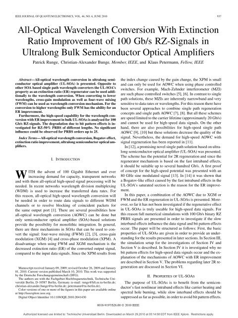
IEEE JOURNAL OF QUANTUM ELECTRONICS, VOL. 46, NO. 6, JUNE 2010 937<br />
<strong>All</strong>-<strong>Optical</strong> <strong>Wavelength</strong> <strong>Conversion</strong> <strong>With</strong> <strong>Extinction</strong><br />
<strong>Ratio</strong> Improvement of 100 Gb/s RZ-Signals in<br />
Ultralong Bulk Semiconductor <strong>Optical</strong> Amplifiers<br />
Patrick Runge, Christian-Alexander Bunge, Member, IEEE, and Klaus Petermann, Fellow, IEEE<br />
Abstract—<strong>All</strong>-optical wavelength conversion in ultralong semiconductor<br />
optical amplifier (UL-SOA) is presented. Opposite to<br />
other SOA based single path wavelength converters the UL-SOA’s<br />
property as an extinction ratio (ER) regenerator can be used additionally<br />
to the wavelength conversion. When converting to lower<br />
wavelengths, cross-gain modulation as well as four-wave mixing<br />
(FWM) can be used as wavelength conversion mechanism. For the<br />
conversion to higher wavelengths only FWM has the ability for an<br />
ER improvement.<br />
Furthermore, the high-speed capability for the wavelength conversion<br />
with ER improvement in bulk UL-SOAs is analysed for 100<br />
Gb/s RZ-signals. The degradation due to bit pattern effects is investigated<br />
for RZ-50% PRBS of different lengths. No significant<br />
influence could be observed for PRBS orders up to 25.<br />
Index Terms—<strong>All</strong>-optical wavelength conversion, Bogatov effect,<br />
extinction ratio improvement, ultralong semiconductor optical amplifiers.<br />
I. INTRODUCTION<br />
WITH the advent of 100 Gigabit Ethernet and ever<br />
increasing demand for capacity, transparent networks<br />
and with them all-optical high-speed signal processing will be<br />
needed. In recent networks wavelength division multiplexing<br />
(WDM) is used to increase the transferred data rates. For<br />
this reason, all-optical high-speed wavelength conversion will<br />
be needed in order to route data signals to different WDM<br />
channels or to resolve blocking of coincident packets for<br />
the same output port [1]. There are several possibilities how<br />
all-optical wavelength conversion (AOWC) can be done but<br />
only semiconductor optical amplifier (SOA)-based solutions<br />
provide the possibility for monolithic integration. In general,<br />
there are three mechanisms in SOAs that can be used to convert<br />
the signal: four-wave mixing (FWM) [2], [3], cross-gain<br />
modulation (XGM) [4] and cross-phase modulation (XPM). A<br />
disadvantage when using FWM and XGM mechanism is the<br />
decreased extinction ratio (ER) of the converted output signal,<br />
compared to the input data signals. Since the XPM results from<br />
Manuscript received January 09, 2009; revised October 26, 2009 and January<br />
01, 2010. Current version published March 10, 2010. This work was supported<br />
by the Deutsche Forschungsgemeinschaft (DFG).<br />
The authors are with the Fachgebiet Hochfrequenztechnik, Technische Universität<br />
Berlin, D-10587 Berlin, Germany (e-mail: runge@hft.ee.tu-berlin.de;<br />
christian-alexander.bunge@tu-berlin.de; petermann@tu-berlin.de).<br />
Color versions of one or more of the figures in this paper are available online<br />
at http://ieeexplore.ieee.org.<br />
Digital Object Identifier 10.1109/JQE.2010.2041430<br />
the index change caused by the gain change, the XPM is small<br />
and can only be used for AOWC when using phase controlled<br />
switches. For example, Mach-Zehnder interferometer (MZI)<br />
are such phase controlled switches [5], [6]. In contrast to single<br />
path solutions, these MZIs are inherently narrowband and very<br />
sensitive to data rates or wavelengths. For this reason there have<br />
been several approaches to combine single path regeneration<br />
concepts and single path AOWC [7], [8]. But all these schemes<br />
are speed limited to the carrier lifetime (approximately 20 Gb/s)<br />
and cannot be used for high-speed data signals. On the other<br />
hand, there are also possibilities for high-speed single path<br />
AOWC [9], [10] but these solutions decrease the quality of the<br />
signal. Nevertheless, the demand for high-speed AOWC with<br />
signal regeneration has been reported in [11].<br />
In [12], a promising novel single path solution based on ultralong<br />
semiconductor optical amplifier (UL-SOA) was presented.<br />
The scheme has the potential for 2R regeneration and since the<br />
regenerator mechanism is based on the fast intraband effects,<br />
it should be suitable up to several hundred Gb/s. A first proof<br />
of concept for the high-speed potential was presented with an<br />
80 GHz sine modulated signal [13]. In [14] it was shown that<br />
a Bogatov-like effect caused by the fast intraband effects in the<br />
UL-SOA’s saturated section is the reason for the ER improvement.<br />
In this paper, a combination of the AOWC due to XGM or<br />
FWM and the ER regeneration in UL-SOAs is presented. Moreover,<br />
so far it has not been investigated if the regenerative effect<br />
in UL-SOAs is truly useable for high-speed data signals. For<br />
this reason full numerical simulations with 100 Gb/s binary RZ<br />
PRBS signals are presented in order to investigate if the slow<br />
interband effects influence the data signal and bit pattern effects<br />
occur. The paper will be structured as follows: First, the basic<br />
properties of UL-SOAs are given in order to provide an understanding<br />
for the results presented in later sections. In Section III,<br />
the simulation setup for the investigations of Section IV and<br />
Section V is described. In Section IV it is investigated why no<br />
bit pattern effects for high-speed data signals occur and the explanation<br />
of the mechanisms of AOWC with ER improvement<br />
are described in Section V. The problems regarding later 2R regeneration<br />
are discussed in Section VI.<br />
II. PROPERTIES OF UL-SOAS<br />
The purpose of UL-SOAs is to benefit from the semiconductor’s<br />
fast nonlinear intraband effects like carrier heating and<br />
spectral hole burning, while slow interband effects should be<br />
suppressed as far as possible, in order to avoid bit pattern effects.<br />
0018-9197/$26.00 © 2010 IEEE<br />
Authorized licensed use limited to: Technische Universitaet Berlin. Downloaded on March 29,2010 at 05:14:58 EDT from IEEE Xplore. Restrictions apply.
938 IEEE JOURNAL OF QUANTUM ELECTRONICS, VOL. 46, NO. 6, JUNE 2010<br />
Fig. 2. Conceptual setup of the wavelength converter including the ER improvement;<br />
is either , +1 or 0 1 depending which<br />
kind of wavelength conversion mechanism shall be used.<br />
III. SIMULATION SETUP<br />
Fig. 1. Probe signal’s amplification asymmetry due to the dynamical part of the<br />
gain suppressions in the UL-SOA’s saturated section (1 = 0 ;<br />
jE j P ).<br />
Unlike in SOAs, the main part of UL-SOAs is saturated by<br />
the amplified signals and the amplified spontaneous emission<br />
(ASE) noise after a certain length. For this reason, UL-SOAs<br />
can be regarded as being divided into an amplifying section<br />
and a saturated section. For bulk SOAs with typical dimensions,<br />
the transition between these sections takes place after approximately<br />
1 mm of propagation. The amplifying section has the<br />
same properties as a short SOA and the saturated section can be<br />
regarded as another device with different properties. Because of<br />
the high optical power after the amplifying section, the carrier<br />
density in the saturated section is fixed to the net transparency<br />
level. If the signal levels change much faster than the carrier lifetime,<br />
the carrier density in the amplifying section is only dependent<br />
on the average optical power. If the signal remains at one<br />
of the states longer than the carrier lifetime, the length and the<br />
gain of the amplifying section changes. As a result bit pattern effects<br />
occur. For high data rates with fast changing signal states,<br />
the performance is not limited by the slow interband effects.<br />
Only the fast nonlinear intraband effects influence the signals in<br />
the saturated section. Their response time is about 1000 times<br />
shorter compared to the slow interband effects, but their impact<br />
is also weaker. For this reason, the desired operation point for<br />
signal processing is when the carrier density inside the UL-SOA<br />
is shifted as far as possible towards the front of the device in<br />
order to efficiently use the length of the device and to avoid the<br />
influence of back-propagating ASE.<br />
Moreover, the UL-SOA shows a Bogatov-like effect over several<br />
nm due to the increased efficiency of the fast intraband effects.<br />
In [15] Bogatov has demonstrated that the beating of two<br />
input signals creates dynamic gain and index gratings in nonlinear<br />
semiconductor media. Because of the interaction of these<br />
dynamic gratings, the weaker signal’s amplification is dependent<br />
on the stronger signal’s wavelength detuning. Due to the<br />
-factor causing the index pulsation, the probe signal is stronger<br />
amplified on the longer wavelength side of the pump signal<br />
(Fig. 1). In [15] the pulsations are due to the slow interband<br />
effects, while in [14], [16] a similar effect based on the fast intraband<br />
effects was presented. Due to the fast intraband effects,<br />
this Bogatov-like effect is suitable for high-speed operations.<br />
The conceptual setup of the AOWC with ER improvement<br />
is shown in Fig. 2. Due to the two input signals, a parametric<br />
amplification of the data signal in dependence of the CW signal<br />
can be obtained, resulting in a nonlinear transfer characteristic<br />
over<br />
. <strong>With</strong> the help of the nonlinear<br />
gain characteristic, the ER can be improved. To achieve<br />
a maximum ER improvement the UL-SOA’s operating point is<br />
set at a steep slope of the nonlinear transfer characteristic.<br />
The investigated device is a 4 mm-long bulk SOA. The geometrical<br />
structure has been optimised in order to increase the<br />
efficiency of the nonlinear effects (decreased coupling losses<br />
and increased mode confinement [20]). The values are given in<br />
Table I. The driving current is 300 mA/mm.<br />
In later applications the presented scheme might be used<br />
at a switching node in long-haul transmission systems. After<br />
being transmitted over several spans, a degenerated channel<br />
approaches the node. First the whole channel will be optically<br />
amplified with an EDFA before the WDM channel of interest<br />
will be converted to the new wavelength. For this reason, we<br />
assume the following parameters for the input data signal after<br />
an EDFA: , . The power for<br />
the additionally injected CW is:<br />
. The signals’<br />
wavelength are 1560 nm and 1564 nm, respectively. The<br />
wavelength alignment depends on which kind of wavelength<br />
conversion mechanism shall be used. The data signals being<br />
investigated are 100 Gb/s OOK-RZ-50% modulated PRBSs<br />
of orders up to 25. The bandpass filter after the UL-SOA<br />
is a second-order Gaussian filter with a 3 dB-bandwidth of<br />
275 GHz.<br />
Due to limited computation capacity it was not possible to<br />
simulate complete PRBSs longer than . For this reason,<br />
critical bit sequences were taken to estimate the impact of pattern<br />
effects on the regeneration scheme. As already mentioned<br />
in Section II, pattern effects occur if the data signal remains long<br />
at one of the states. Therefore, the critical bit sequences contain<br />
various combinations of the following bit sequences: constant<br />
signal states, one inverted bit within a constant signal state and<br />
alternating bit sequences. These combinations of bit sequences<br />
are expected to create worst-case bit pattern effects. A detailed<br />
description of the critical bit sequence is given in the Appendix .<br />
The simulations have been done with the same model as in<br />
[21], [22] where a very good match between measurements and<br />
simulation results has been demonstrated.<br />
Authorized licensed use limited to: Technische Universitaet Berlin. Downloaded on March 29,2010 at 05:14:58 EDT from IEEE Xplore. Restrictions apply.
RUNGE et al.: ALL-OPTICAL WAVELENGTH CONVERSION WITH EXTINCTION RATIO IMPROVEMENT 939<br />
TABLE I<br />
PARAMETERS OF THE BULK SOA USED IN THE SIMULATIONS; THE MATERIAL<br />
PARAMETERS HAVE BEEN TAKEN FROM LITERATURE [13], [17]–[19]<br />
Fig. 3. Eye diagram for a PRBS with the length of 2 0 1 after the bandpass<br />
filter at without additional CW at the input; the signal is totally distorted<br />
due to bit pattern effects, saturation effects and SPM.<br />
IV. PATTERN EFFECTS FOR HIGH-SPEED SIGNALS<br />
In general the speed of bulk SOAs for all-optical signal processing<br />
is limited to approximately 20 Gb/s due to the carrier<br />
lifetime. Bulk UL-SOAs in contrast should be usable for signal<br />
processing of data signals with transmission rates fairly above<br />
the carrier lifetime. For SOAs under usual driving conditions,<br />
bit pattern effects are expected for 100 Gb/s so that the existence<br />
of bit pattern effects needs to be further investigated.<br />
Fig. 3 shows the eye diagram of a 100 Gb/s data signal before<br />
and after the UL-SOA that has been exclusively injected into<br />
the UL-SOA. As expected, the eye diagram at the UL-SOA’s<br />
output is totally distorted due to multiple effects: bit pattern effects,<br />
gain saturation, self-phase modulation (SPM) and ASE.<br />
Since 100 Gb/s are not fairly above the carrier lifetime, it is not<br />
clear how big the contribution to the distortions due to bit pattern<br />
effects are. For this reason, the standard deviation of the signal<br />
levels at the maximum eye opening in dependence on the equivalent<br />
PRBS order is evaluated (Fig. 4). <strong>With</strong> increasing equivalent<br />
PRBS order, the standard deviation of the signal states increases<br />
resulting in a decreasing signal quality. The tremendous<br />
increase of the standard deviation’s “1”-level between the first<br />
and fourth equivalent PRBS order can be ascribed to the growing<br />
overshoot on top of the eye opening. Moreover, the simulation<br />
Fig. 4. Standard deviation of the signal levels at the maximum eye opening in<br />
dependence of an equivalent PRBS order after the bandpass filter without additional<br />
CW signal (corresponding to Fig. 3; solid lines: true PRBS and dashed<br />
lines: critical sequence).<br />
shows that after a PRBS order of 4 the distortions due to bit pattern<br />
effects stagnate.<br />
When injecting the data signal with an additional CW signal<br />
that is orthogonally polarised into the UL-SOA, a clearly<br />
opened eye diagram can be observed at the output of the<br />
UL-SOA (Fig. 5). Also, the data signal has been amplified<br />
by 12 dB. The amplification is about half as much as the<br />
amplification for the case with the exclusive transmission of<br />
the data signal through the UL-SOA because the gain equally<br />
distributes to the data signal and the CW signal. Furthermore,<br />
the ER of the data signal has been reduced from 6 dB to 1.5 dB.<br />
The investigation of the signal levels’ standard deviation shows<br />
that for the case with the orthogonally polarised additional CW,<br />
nearly no bit pattern effects can be observed (Fig. 6). Only a<br />
very slight increase between a PRBS order of 1 and 2 can be<br />
observed so that the influence of bit pattern effects is negligible.<br />
For this reason, the additional CW signal can be regarded as a<br />
holding beam successfully suppressing bit pattern effects.<br />
Authorized licensed use limited to: Technische Universitaet Berlin. Downloaded on March 29,2010 at 05:14:58 EDT from IEEE Xplore. Restrictions apply.
940 IEEE JOURNAL OF QUANTUM ELECTRONICS, VOL. 46, NO. 6, JUNE 2010<br />
Fig. 5. Eye diagram for the converted signal at ; the input signal has been<br />
a PRBS with the length of 2 0 1 at ; compared to the input signal, the<br />
output signal has been amplified but the ER has been decreased to 1.9 dB.<br />
Fig. 7. Carrier density distribution along the propagation direction for infinite<br />
long constant signal levels of the data signal.<br />
8 mm-long device in [21]. As a result, there is less back-propagating<br />
ASE, shifting the carrier density peak towards the front<br />
of the UL-SOA contributing to a stable operation point.<br />
In the eye diagram of Fig. 5 still a broadening of the data<br />
signal’s traces at the UL-SOA’s output can be seen although the<br />
bit pattern effects are negligible. Since the trace broadening can<br />
also be observed for sine modulated signals where no bit pattern<br />
effects are expected at all because half the sine’s time period is<br />
much shorter than the carrier life time. When investigating the<br />
field intensity’s<br />
relative standard deviation of the<br />
“0”-level and the “1”-level and their distribution, for both signal<br />
levels a Gaussian distribution with an equal relative standard<br />
deviation can be observed. As a result, the trace broadening can<br />
be ascribed to ASE.<br />
Fig. 6. Standard deviation of the optical signal levels at the maximum eye<br />
opening in dependence of an equivalent PRBS order after the bandpass filter<br />
with co-polarised additional CW signal (corresponding to Fig. 5; solid lines:<br />
true PRBS and dashed lines: critical sequence).<br />
To prove the efficiency of the CW signal as a holding beam,<br />
the carrier density distribution inside the UL-SOA along the<br />
propagation direction has to be regarded. Fig. 7 shows the<br />
steady-state carrier density for infinite long constant signal<br />
levels. For the case with an additional CW signal, the carrier<br />
density peak would shifts by 1.5% of the device length when<br />
a worst-case transition after a very long constant signal state<br />
appears. For the case without additional CW signal, the carrier<br />
density peak shifts by 9.5% of the device length resulting in<br />
a mentionable change of the operation point. Moreover, the<br />
smallish shifts of the carrier density peak also have to be related<br />
to the UL-SOA’s driving conditions and the optimised device.<br />
First of all, the low coupling losses and the high optical input<br />
power deeply saturate the UL-SOA even for a data signal’s<br />
“0”-level. Moreover, the low input extinction ratio only results<br />
in a small shift of the carrier density peak for a worst case<br />
transition. Another aspect is the optimised geometry of the<br />
device, increasing the efficiency of the nonlinear intraband<br />
effects. Hence, the UL-SOA can be shortened compared to the<br />
V. AOWC WITH ER IMPROVEMENT<br />
In the previous section it has been shown that due to an additional<br />
CW signal also transmission rates above the carrier lifetime<br />
are possible. Unfortunately, due to saturation effects the<br />
ER of the data signal has been decreased dramatically (Fig. 9)<br />
making the data signal useless for further transmission.<br />
In [14], [21] has been presented when injecting the addition<br />
CW signal parallel to the data signal into the UL-SOA,<br />
an ER improvement can be achieved due to a Bogatov-like<br />
effect. Since the scheme is sensitive to the input power ratio<br />
, Fig. 9 shows the signal’s ER after the UL-SOA<br />
and the bandpass filter at different wavelengths for two different<br />
wavelength alignments of the input signals. The results<br />
illustrate that wavelength conversion with ER improvement<br />
due to XGM or FWM as wavelength conversion mechanism is<br />
possible. In order to select the AOWC mechanism that should<br />
be used, the wavelength alignment and the CW signal’s power<br />
have to be set correctly.<br />
A. AOWC <strong>With</strong> ER Improvement Due to XGM<br />
In [21], it has been demonstrated that the data signal has to<br />
be located on the shorter wavelength side of the CW signal in<br />
order to obtain an ER improvement for the data signal (circle-<br />
Authorized licensed use limited to: Technische Universitaet Berlin. Downloaded on March 29,2010 at 05:14:58 EDT from IEEE Xplore. Restrictions apply.
RUNGE et al.: ALL-OPTICAL WAVELENGTH CONVERSION WITH EXTINCTION RATIO IMPROVEMENT 941<br />
Fig. 8. <strong>Extinction</strong> ratio measured at different wavelength in dependence of the input signals’ power ratio for a 100 Gb/s RZ50% OOK signal (left: <<br />
and right: < ), is the first FWM product on the shorter wavelength side of the input signals and is the first FWM product on the longer<br />
wavelength side of the input signals.<br />
symbol lines of Fig. 8(b)). For the opposite wavelength alignment,<br />
the data signal’s ER decreases as the circle-symbol lines<br />
in Fig. 8(a)) show. For AOWC with ER improvement due to<br />
XGM the wavelength alignment has to be swapped (up-trianglesymbol<br />
lines of Fig. 8(a)). The reason for the opposite wavelength<br />
alignment can be explained by Fig. 1. Similar to the solo<br />
ER improvement case (without AOWC) described in [14], the<br />
gain-suppressing part of the probe signal’s amplification asymmetry<br />
(positive wavelength detuning) is used to achieve the ER<br />
improvement. When investigating how the signals’ power develop<br />
inside the UL-SOA, the data signal becomes the stronger<br />
pump signal and its modulation influences the weaker probe<br />
(CW signal). Since the CW signal has been cross-gain modulated<br />
in the UL-SOA’s saturated section, its modulation is inverse<br />
to the data signal’s modulation. Furthermore, the intensity<br />
of the Bogatov-like effect is dependent on the pump signal’s<br />
power (data signal’s power). For this reason the CW’s “1”-<br />
level is less suppressed than the “0”-level resulting in an increasing<br />
ER.<br />
Moreover, Fig. 8 shows that the ER improvement efficiency<br />
for the wavelength conversion case is approximately 3 dB better<br />
than for the solo ER improvement case. In both cases, the ER<br />
improved signal is the probe and for this reason the ER improvement<br />
efficiency is dependent on the pump’s modulation<br />
depth (ER). In the second part of the UL-SOA’s saturated section<br />
where the ER improvement takes place the pump’s modulation<br />
is strong for the wavelength conversion case. For the<br />
solo ER improvement case, the pump signal (CW) is dependent<br />
on the XGM efficiency of the first part of the UL-SOA’s<br />
saturated section wether for the wavelength conversion case the<br />
pump (data signal) is modulated from the beginning.<br />
Fig. 9 shows an eye diagram of a wavelength converted and<br />
ER improved 100 Gb/s RZ-data signal for an input power ratio<br />
of 1 dB. After the bandpass filter where the signal has been<br />
filtered from ASE and the original data signal, the converted<br />
signal’s “1”-level has been amplified by 7.5 dB and the ER has<br />
been increased from 6 dB to 13 dB.<br />
Fig. 9. Eye diagram for a PRBS with the length of 2 0 1 after the bandpass<br />
filter; the mechanism for the wavelength conversion has been XGM so that the<br />
data signal was inversely converted to .<br />
B. AOWC <strong>With</strong> ER Improvement Due to FWM<br />
The AOWC with ER improvement due to XGM from the<br />
previous subsection has only the ability to convert to a shorter<br />
wavelength. When using FWM as wavelength conversion mechanism<br />
instead of XGM, up and down conversion with ER improvement<br />
can be realised. Moreover, the converted signal is<br />
not inversely modulated to the original input data signal.<br />
1) Converting to Longer <strong>Wavelength</strong>s: When increasing the<br />
input power of the CW signal to 9 dBm and setting the wavelength<br />
alignment to<br />
, AOWC to longer wavelengths<br />
with ER improvement can be achieved. The power of<br />
the signal after the UL-SOA and the bandpass is about equal<br />
compared to the data signal’s input power and the ER slightly<br />
increased from 6 dB to 7 dB so that the ER improvement mainly<br />
compensates the ER degeneration due to the saturation effects.<br />
The reason for the worse ER improvement compared to the<br />
AOWC with ER improvement due to XGM and the solo ER<br />
improvement can be figured out when the mechanism of the<br />
Authorized licensed use limited to: Technische Universitaet Berlin. Downloaded on March 29,2010 at 05:14:58 EDT from IEEE Xplore. Restrictions apply.
942 IEEE JOURNAL OF QUANTUM ELECTRONICS, VOL. 46, NO. 6, JUNE 2010<br />
Fig. 10. Output spectra of the UL-SOA for a FWM wavelength converted 100 Gb/s RZ50% OOK signal for an input power ratio (P =P ) of 8 dB (left:<br />
conversion to higher wavelengths and right: conversion to lower wavelengths), the red graph illustrates the relevant Bogatov-like effect causing the ER improvement<br />
at .<br />
ER improvement is further investigated. In the UL-SOA’s saturated<br />
section the signal is FWM converted to . Since<br />
the data signal’s ER decreases while propagating through the<br />
UL-SOA also the ER of the wavelength converted signal is low.<br />
In the second part of the UL-SOA’s saturated section, the ER<br />
is improved by the Bogatov-like effect. Opposite to the previously<br />
discussed ER improvement mechanisms, the amplifying<br />
part of the probe’s amplification asymmetry of Fig. 1 (negative<br />
wavelength detuning) is used to achieve the ER improvement<br />
(Fig. 10(a)). During the whole conversion, the converted signal<br />
has less power than the original data signal. For this reason.<br />
the converted signal will be refereed to as the probe and to the<br />
original signal as the pump. Since the probe and the pump have<br />
the same modulation and the efficiency of the Bogatov-like effect<br />
is dependent on the pump’s power, the probe’s “1”-level<br />
is more amplified than the “0”-level resulting in an increasing<br />
ER. Because of the Bogatov-like effect is small for a negative<br />
wavelength detuning compared to the positive wavelength detuning<br />
also the efficiency of the ER improvement decreases. Although,<br />
the CW signal in Fig. 10(a) has more power than the<br />
data signal, its Bogatov-like effect does not cause the ER improvement.<br />
First of all, the Bogatov-like effect is negligible over<br />
such a large negative wavelength detuning and secondly the CW<br />
signal is inversely modulated to the converted signal resulting in<br />
a decreasing ER in combination with a negative wavelength detuning.<br />
2) Converting to Shorter <strong>Wavelength</strong>s: Keeping the input<br />
power of the CW signal at 9 dBm but changing the wavelength<br />
alignment to<br />
, AOWC to shorter wavelengths<br />
with ER improvement is achieved. The power of the signal after<br />
the UL-SOA and the bandpass has been decreased by about 1<br />
dB compared to the data signal’s input power and the ER also<br />
slightly increased from 6 dB to 7 dB so that the ER improvement<br />
mainly compensates the ER degeneration due to the saturation<br />
effects. Again, the small ER improvement efficiency can be revealed<br />
when a closer look is taken on how the Bogatov-like effect<br />
influences the converted signal. Similar to the other FWM<br />
case, the signal is FWM converted to<br />
with a decreased<br />
ER in the UL-SOA’s saturated section while the ER<br />
improvement only takes place in the second part of the saturated<br />
section. In general, one would expect that the converted<br />
signal with low power (probe) is influenced by the stronger data<br />
signal but due to the higher input power ratio, the data signal<br />
is strongly suppressed by the Bogatov-like effect of the CW<br />
signal (Fig. 10(b)). Therefore, the influence of the data signal on<br />
the converted signal due to the Bogatov-like effect is negligible<br />
because of the data signal’s low power. Instead the cross-gain<br />
modulated and strong CW signal can be regarded as the pump<br />
causing the ER improvement. Similar to the solo ER improvement<br />
case, the attenuating part of the Bogatov-like effect in<br />
combination with the inversely modulated pump increases the<br />
ER of the converted signal. So far, the Bogatov-like effect was<br />
only discussed for a signals’ detuning of but in this case<br />
the Bogatov-like effect interacts over decreasing the efficiency<br />
of the ER improvement.<br />
The bit pattern effects are also negligible for the presented<br />
AOWC with ER improvement schemes in this section. As<br />
stressed in Section IV, the inexistence of the bit pattern effects<br />
is caused by the high optical power of the input signals and<br />
the low ER of the data signal. For the XGM case none of<br />
these parameters has changed (only the CW signal is parallelly<br />
polarised to the data signal) and for the FWM case the optical<br />
power of the holding beam (CW signal) had to be increased by<br />
8 dB reducing bit pattern effects even better.<br />
VI. DISCUSSION CONSIDERING 2R-REGENERATION<br />
Since the signal in Fig. 9 has been amplified (re-amplification)<br />
and its ER has been improved (first step in direction<br />
of re-shaping), the presented scheme has the potential for 2R<br />
regeneration. But unfortunately, the traces of the output signal<br />
have been broadened so that the re-shaping condition has not<br />
been met completely because of missing noise compression.<br />
The broadening of the traces can be ascribed to the operating<br />
point of the UL-SOA. Under these driving conditions, the<br />
steep slope of the transfer function is used for a maximum ER<br />
improvement. As a result, a small fluctuation of the optical<br />
power due to ASE will increase the fluctuation because of the<br />
transfer characteristic’s steep slope. A solution for this problem<br />
Authorized licensed use limited to: Technische Universitaet Berlin. Downloaded on March 29,2010 at 05:14:58 EDT from IEEE Xplore. Restrictions apply.
RUNGE et al.: ALL-OPTICAL WAVELENGTH CONVERSION WITH EXTINCTION RATIO IMPROVEMENT 943<br />
would be clipping of the signal levels, being typically obtained<br />
for the “1”-level due to the saturation effects in SOAs. The<br />
inexistence of the gain saturation for the presented scheme is<br />
also indicated by the signals’ output power levels in Fig. 5 and<br />
Fig. 9 being about 5 dB less for the parallel polarised case where<br />
the Bogatov-like effect is enabled. Since the attenuating part<br />
of the Bogatov-like effect is used for the ER improvement, the<br />
output signal’s “1”-level for the AOWC cases with conversion<br />
to shorter wavelengths and for the solo ER improvement case<br />
do not saturate.<br />
For the conversion to longer wavelengths, the amplifying<br />
part of the Bogatov-like effect is used to achieve the ER improvement<br />
so that in general a saturation should be possible but<br />
unfortunately this mechanism is very inefficient (see discussion<br />
in Section V-B). Hence, the UL-SOA’s length needs to be<br />
increased and it might not even be observable in MQW-devices<br />
because of their minor -factor. When decreasing the<br />
-factor, the probe’s gain asymmetry becomes more and more<br />
symmetric and will also lead to attenuation for a negative<br />
wavelength detuning [14] so that the ER improvement mechanism<br />
for conversion to longer wavelengths might no more<br />
workout. In such a case, the wavelength alignment must be<br />
in order that the inverse modulated CW also<br />
improves the ER of the wavelength converted signal. Furthermore,<br />
in MQW-devices the mode confinement is much smaller<br />
also decreasing the efficiency of the effects due to the nonlinear<br />
gain [20] so that an ER improvement might not be observable<br />
in MQW-devices at all.<br />
VII. CONCLUSION<br />
We presented three different schemes for AOWC with ER improvement<br />
in bulk UL-SOAs and proved their high-speed potential<br />
with 100 Gb/s RZ PRBS signals. Numerically, an ER improvement<br />
of 7 dB could be achieved while the signal has been<br />
converted over 4 nm to a shorter wavelength due to XGM with<br />
a 4 mm highly nonlinear bulk device. Unfortunately, this wavelength<br />
conversion is limited to down conversion, but when using<br />
FWM, also up conversion is possible. In this case, however, the<br />
ER improvement efficiency decreases and mainly compensates<br />
degrading effects.<br />
It has been shown that for an optimised device under proper<br />
driving conditions no bit pattern effects will arise up to a word<br />
length of 25 bits. The suppression of the bit pattern effects can<br />
be ascribed to the additional injected CW signal needed for the<br />
wavelength conversion and the Bogatov-like effect causing the<br />
ER improvement.<br />
In the proposed schemes, small fluctuations increase, since<br />
the ER improvement is realised with a steep slope of the nonlinear<br />
transfer characteristic. For later AOWC applications with<br />
2R-regeneration, a clipping of the signal mark levels have to be<br />
performed.<br />
APPENDIX<br />
CRITICAL BIT SEQUENCES<br />
To investigate the impact of bit pattern effects on the presented<br />
scheme, critical bit sequences are used because of<br />
lower computational effort compared to true PRBSs. Fig. 11<br />
Fig. 11. Flowchart for generating a critical bit sequence of the Nth PRBS order;<br />
the generation rule can be applied for even PRBS orders; for odd PRBS orders<br />
the alternating bit sequences have to be extended or shortened by one bit in<br />
order to avoid bit subsequences of the same consecutive bits longer than the<br />
PRBS order.<br />
shows the flowchart how these critical sequences are created.<br />
As an example the 4th order critical bit sequence is:<br />
000010001010000111101110101111.<br />
For the simulation in this article the flowchart has passed<br />
through until sequences of different PRBS orders had a length<br />
of 263 bits.<br />
REFERENCES<br />
[1] S. B. Yoo, “<strong>Optical</strong> packet and burst switching technologies for the<br />
future photonic Internet,” J. Lightw. Technol., vol. 24, no. 12, pp.<br />
4468–4492, 2006.<br />
[2] S. Diez, C. Schmidt, R. Ludwig, H. G. Weber, K. Obermann, S. Kindt,<br />
I. Koltchanov, and K. Petermann, “Four-wave mixing in semiconductor<br />
optical amplifiers for frequency conversion and fast optical switching,”<br />
IEEE Sel. Topics Quantum Electron., vol. 3, no. 5, pp. 1131–1145,<br />
1997.<br />
[3] A. Kelly, A. Ellis, D. Nesset, R. Kashyap, and D. Moodie, “100 Gb/s<br />
wavelength conversion using FWM in an MQW semiconductor optical<br />
amplifier,” Electron. Lett., vol. 34, no. 20, pp. 1955–1956, 1998.<br />
Authorized licensed use limited to: Technische Universitaet Berlin. Downloaded on March 29,2010 at 05:14:58 EDT from IEEE Xplore. Restrictions apply.
944 IEEE JOURNAL OF QUANTUM ELECTRONICS, VOL. 46, NO. 6, JUNE 2010<br />
[4] T. Durhuus, B. Mikkelsen, C. Joergensen, S. L. Danielsen, and K.<br />
Stubkjaer, “<strong>All</strong>-optical wavelength conversion by semiconductor optical<br />
amplifiers,” J. Lightw. Technol., vol. 14, no. 6, pp. 942–954, 1996.<br />
[5] C. Joergensen, S. Danielsen, K. Stubkjaer, M. Schilling, K. Daub, P.<br />
Doussiere, F. Pommerau, P. Hansen, H. Poulsen, A. Kloch, M. Vaa, B.<br />
Mikkelsen, E. Lach, G. Laube, W. Idler, and K. Wunstel, “<strong>All</strong>-optical<br />
wavelength conversion at bit rates above 10 Gb/s using semiconductor<br />
optical amplifiers,” IEEE Sel. Topics Quantum Electron., vol. 3, no. 5,<br />
pp. 1168–1180, 1997.<br />
[6] D. Wolfson, A. Kloch, T. Fjelde, C. Janz, B. Dagens, and M. Renaud,<br />
“40 Gb/s all-optical wavelength conversion, regeneration and demultiplexing<br />
in an SOA-based all-active Mach-Zehnder interferometer,”<br />
IEEE Photon. Technol. Lett., vol. 12, no. 3, pp. 332–334, 2000.<br />
[7] G. Contestabile, R. Proietti, N. Calabretta, and E. Ciaramella,<br />
“Cross-gain compression in semiconductor optical amplifiers,” J.<br />
Lightw. Technol., vol. 25, no. 3, pp. 915–921, 2007.<br />
[8] H. Chayet, S. B. Ezra, N. Shachar, S. Tzadok, S. Tsadka, and J.<br />
Leuthold, “Regenerative all-optical wavelength converter based on<br />
semiconductor optical amplifier and sharp frequency response filter,”<br />
in Proc. OFC, 2004, ThS2.<br />
[9] R. J. Manning, X. Yang, R. P. Webb, R. Giller, F. C. Garcia Gunning,<br />
and A. D. Ellis, “The ‘Turbo-Switch’—A novel technique to increase<br />
the high-speed response of SOAs for wavelength conversion,” in Proc.<br />
OFC, 2006, paper OWS8.<br />
[10] J. Leuthold, L. Möller, J. Jaques, S. Cabot, L. Zhang, P. Bernasconi,<br />
M. Cappuzzo, L. Gomez, E. Laskowski, E. Chen, A. Wong-Foy, and<br />
A. Griffin, “160 Gb/s SOA all-optical wavelength converter and assessment<br />
of its regenerative properties,” Electron. Lett., vol. 40, no. 9, pp.<br />
554–555, 2004.<br />
[11] J. Leuthold, W. Freude, G. Boettger, J. Wang, P. Vorreau, and A. Marculescu,<br />
“Trends in the field of all-optical wavelength conversion and<br />
regeneration for communication up to 160 Gb/s,” in Proc. ECOC, 2005,<br />
Tu.3.3.6.<br />
[12] U. Busolt, G. Bramann, H.-J. Wünsche, C. Schmidt, B. Sartorius,<br />
H.-P. Nolting, and T. Rosin, “Two-wave competition for all-optical<br />
signal processing: First experimental verification in ultra-long SOAs,”<br />
in Proc. ECOC, Rimini, 2003, Th3.5.1.<br />
[13] G. Bramann, H.-J. Wünsche, U. Busolt, C. Schmidt, M. Schlak, B. Sartorius,<br />
and H.-P. Nolting, “Two-wave competition in ultralong semiconductor<br />
optical amplifiers,” IEEE J. Quantum Electron., vol. 41, no.<br />
10, pp. 1260–1267, 2005.<br />
[14] P. Runge, R. Elschner, C.-A. Bunge, and K. Petermann, “<strong>Extinction</strong><br />
ratio improvement in ultralong semiconductor optical amplifiers,”<br />
IEEE J. Quantum Electron., vol. 45, no. 6, pp. 578–585, 2009.<br />
[15] A. Bogatov, P. Eliseev, and B. Sverdlov, “Anomalous interaction of<br />
spectral modes in a semiconductor laser,” IEEE J. Quantum Electron.,<br />
vol. 11, no. 7, pp. 510–515, 1975.<br />
[16] A. Uskov, J. Mørk, and J. Mark, “Wave mixing in semiconductor laser<br />
amplifiers due to carrier heating and spectral-hole burning,” IEEE J.<br />
Quantum Electron., vol. 30, no. 8, pp. 1769–1781, 1994.<br />
[17] A. Mecozzi and J. Mørk, “Saturation effects in nondegenerate fourwave<br />
mixing between short optical pulses in semiconductor laser amplifiers,”<br />
IEEE J. Quantum Electron., vol. 3, no. 5, pp. 1190–1207,<br />
1997.<br />
[18] G. Toptchiyski, S. Kindt, K. Petermann, E. Hilliger, S. Diez, and H.<br />
G. Weber, “Time-domain modeling of semiconductor optical amplifiers<br />
for OTDM applications,” J. Lightw. Technol., vol. 17, no. 12, pp.<br />
2577–2583, 1999.<br />
[19] J. Leuthold, M. Mayer, J. Eckner, G. Guekos, H. Melchior, and C.<br />
Zellweger, “Material gain of bulk 1.55 m InGaAsP/InP semiconductor<br />
optical amplifiers approximated by a polynomial model,” J.<br />
Appl. Phys., vol. 87, no. 1, pp. 618–620, 2000.<br />
[20] P. Runge, R. Elschner, and K. Petermann, “Optimising four-wave<br />
mixing in ultralong SOAs,” in Proc. NUSOD ’09, Gwangju, 2009.<br />
[21] P. Runge, R. Elschner, C.-A. Bunge, K. Petermann, M. Schlak, W.<br />
Brinker, and B. Sartorius, “Operational conditions for the extinction<br />
ratio improvement in ultralong SOAs,” IEEE Photon. Technol. Lett.,<br />
vol. 21, no. 2, pp. 106–108, 2009.<br />
[22] P. Runge, K. Petermann, W. Brinker, M. Schlak, and B. Sartorius, “Supercontinuum<br />
generating in ultralong SOAs—Theory and experiment,”<br />
in Proc. ECOC, Vienna, Austria, 2009.<br />
Patrick Runge was born in Berlin, Germany, in 1979. He received the Dipl.-Ing.<br />
degree in computer science from the Technische Universität Berlin, Germany,<br />
in 2005.<br />
From 2005 to 2007 he was with Hymite GmbH, where he was involved in<br />
the design and measurement of optoelectronic packages for optical communication.<br />
In 2007, he returned to the Technische Universität Berlin to pursue the<br />
Ph.D. degree, where he is currently researching the physics and applications of<br />
ultralong semiconductor optical amplifiers.<br />
Christian-Alexander Bunge (S’01–A’02–M’03) was born in Berlin, Germany,<br />
in 1973. He received the Dipl.-Ing. degree in electrical engineering from university<br />
of technology Berlin (TU Berlin) in 1999. Until 2002, he was with TU<br />
Berlin’s photonics group of Prof. Petermann, where he received his Ph.D.<br />
From 2002 to 2004, he was with the Polymer <strong>Optical</strong> Fiber Application<br />
Center (POF-AC) in Nuremberg, where he was responsible for fibre modelling<br />
and short-haul systems design. In 2004, he joined the TU Berlin as senior scientist,<br />
working on high-speed optical transmission systems, studying nonlinear<br />
optics, and modelling of optical components. In 2009, he became professor<br />
at Deutsche Telekom’s university for telecommunication in Leipzig, where<br />
his main research interests are short-haul and access transmission techniques,<br />
multimode glass and polymer-fibre links, and signal processing.<br />
Klaus Petermann (M’76–SM’85–F’09) was born in Mannheim, Germany in<br />
1951. He received the Dipl.-Ing. degree in 1974 and the Dr.-Ing. degree in 1976,<br />
both in electrical engineering from the Technische Universität Braunschweig,<br />
Germany.<br />
From 1974 to 1976, he was a Research Associate at the Institut für Hochfrequenztechnik,<br />
Technische Universität Braunschweig, where he worked on<br />
optical waveguide theory. From 1977 to 1983, he was with AEG-Telefunken,<br />
Forschungsinstitut, Ulm, Germany, where he was engaged in research work<br />
on semiconductor lasers, optical fibers, and optical fiber sensors. In 1983, he<br />
became a Full Professor at the Technische Universität Berlin, Germany. His<br />
current research interests include optical fiber communications and integrated<br />
optics.<br />
Dr. Petermann is a member of the Berlin-Brandenburg Academy of Science.<br />
He is the recipient of the Leibniz Award from the Deutsche Forschungsgemeinschaft<br />
in 1993, and the Distinguished Lecturer Award from the Laser and<br />
Electro-Optics Society within the IEEE in 1999/2000. From 1999 to 2004, he<br />
was an Associate Editor of the IEEE PHOTONICS TECHNOLOGY LETTERS. From<br />
1996 to 2004, he was a member of the board of the Verband Der Elektrotechnik<br />
Elektronik Informationstechnik (VDE). From 2004 to 2006, he was the Vice<br />
President for research at the Technische Universität Berlin.<br />
Authorized licensed use limited to: Technische Universitaet Berlin. Downloaded on March 29,2010 at 05:14:58 EDT from IEEE Xplore. Restrictions apply.