Operational Conditions for Extinction Ratio Improvement in Ultralong ...
Operational Conditions for Extinction Ratio Improvement in Ultralong ...
Operational Conditions for Extinction Ratio Improvement in Ultralong ...

Create successful ePaper yourself
Turn your PDF publications into a flip-book with our unique Google optimized e-Paper software.
106 IEEE PHOTONICS TECHNOLOGY LETTERS, VOL. 21, NO. 2, JANUARY 15, 2009<br />
<strong>Operational</strong> <strong>Conditions</strong> <strong>for</strong> <strong>Ext<strong>in</strong>ction</strong> <strong>Ratio</strong><br />
<strong>Improvement</strong> <strong>in</strong> <strong>Ultralong</strong> SOAs<br />
Patrick Runge, Robert Elschner, Student Member, IEEE, Christian-Alexander Bunge, Member, IEEE,<br />
Klaus Petermann, Senior Member, IEEE, Michael Schlak, Walter Br<strong>in</strong>ker, and Bernd Sartorius<br />
Abstract—The ext<strong>in</strong>ction ratio (ER) improvement <strong>in</strong> ultralong<br />
semiconductor optical amplifiers (UL-SOAs) is studied <strong>in</strong> dependence<br />
on their driv<strong>in</strong>g conditions. A stable process potentially<br />
useful <strong>for</strong> simple high-speed all-optical regeneration is observed.<br />
Furthermore, results <strong>in</strong>dicate that a Bogatov-like effect is the<br />
reason <strong>for</strong> the ER improvement <strong>in</strong> the UL-SOA’s saturated section.<br />
Index Terms—All-optical, Bogatov effect, ext<strong>in</strong>ction ratio<br />
(ER) improvement, ultralong semiconductor optical amplifiers<br />
(UL-SOAs).<br />
I. INTRODUCTION<br />
T<br />
HE regeneration of data signals is an important issue<br />
<strong>for</strong> long-haul optical communication systems. With <strong>in</strong>creas<strong>in</strong>g<br />
data rates, all-optical solutions are needed to overcome<br />
the electronic bottleneck. Opposite to regeneration concepts<br />
with highly nonl<strong>in</strong>ear fibers, most semiconductor optical amplifier<br />
(SOA) schemes can be <strong>in</strong>tegrated. Typical SOA solutions<br />
are based on <strong>in</strong>herently narrowband <strong>in</strong>terferometer structures<br />
[1], [2] and are due to the two <strong>in</strong>terferometer paths sensitive to<br />
data rates and wavelengths. In [3], a new s<strong>in</strong>gle path technique<br />
that uses the SOA’s nonl<strong>in</strong>ear ga<strong>in</strong> characteristic is presented.<br />
S<strong>in</strong>ce this scheme is dependent on the slow <strong>in</strong>terband effects,<br />
the transmission speed is limited due to the carrier lifetime<br />
(several hundred picoseconds). A novel s<strong>in</strong>gle path ext<strong>in</strong>ction<br />
ratio (ER) regeneration concept also us<strong>in</strong>g the nonl<strong>in</strong>ear<br />
transfer function of ultralong SOAs (UL-SOA), was presented<br />
<strong>in</strong> [4]. This regenerator concept is based on the two-wave<br />
competition (TWC) work<strong>in</strong>g with the fast <strong>in</strong>traband effects.<br />
For this reason, the speed limitation should be <strong>in</strong> the range of<br />
several hundred gigabits per second. An analytic description<br />
of the ER improvement, where the TWC effect is expla<strong>in</strong>ed<br />
with the help of four-wave mix<strong>in</strong>g, is given <strong>in</strong> [5]. In addition,<br />
simulations as well as measurements <strong>for</strong> s<strong>in</strong>e-modulated signals<br />
were presented. In [6], a basic set of the UL-SOAs’ driv<strong>in</strong>g<br />
conditions <strong>for</strong> the ER improvement have been <strong>in</strong>vestigated.<br />
In this letter, further detailed experiments on the UL-SOAs<br />
driv<strong>in</strong>g conditions are made. Due to a systematic variation of the<br />
Manuscript received April 14, 2008; revised September 12, 2008. Current<br />
version published January 14, 2009. This work was supported by the Deutsche<br />
Forschungsgeme<strong>in</strong>schaft (DFG).<br />
P. Runge, R. Elschner, C.-A. Bunge, and K. Petermann are with the Fachgebiet<br />
Hochfrequenztechnik, Technische Universität Berl<strong>in</strong>, D-10587 Berl<strong>in</strong>, Germany<br />
(e-mail: runge@hft.ee.tu-berl<strong>in</strong>.de).<br />
M. Schlak, W. Br<strong>in</strong>ker, and B. Sartorius are with the Fraunhofer-Institut<br />
für Nachrichtentechnik, He<strong>in</strong>rich-Hertz-Institut, D-10587 Berl<strong>in</strong>, Germany<br />
(e-mail: sartorius@hhi.fhg.de).<br />
Color versions of one or more of the figures <strong>in</strong> this letter are available onl<strong>in</strong>e<br />
at http://ieeexplore.ieee.org.<br />
Digital Object Identifier 10.1109/LPT.2008.2008910<br />
driv<strong>in</strong>g conditions, the UL-SOA’s optimal operat<strong>in</strong>g po<strong>in</strong>t <strong>for</strong><br />
the ER improvement was found. In addition, it could be proven<br />
that the ER improvement <strong>in</strong> UL-SOAs is a stable process. Furthermore,<br />
some of the experiments <strong>in</strong>dicate that a Bogatov-like<br />
effect (see Section II) <strong>in</strong> the UL-SOA’s saturated section seems<br />
to be the reason <strong>for</strong> the ER improvement.<br />
II. PROPERTIES OF UL-SOAs<br />
Opposite to short SOAs, the major part of UL-SOAs is deeply<br />
saturated due to the amplified <strong>in</strong>put signals and the amplified<br />
spontaneous emission (ASE). For this reason, the UL-SOA<br />
can be divided <strong>in</strong>to two sections: In the amplify<strong>in</strong>g section,<br />
the carrier density cannot follow high-speed modulated signals<br />
because of the long carrier lifetime. As long as the signal<br />
changes are fast enough, the carrier density experiences the<br />
average signal power and no pattern effects occur. By contrast,<br />
<strong>in</strong> the saturated section, the carrier density is clamped to the net<br />
transparency level and only the fast <strong>in</strong>traband effects <strong>in</strong>fluence<br />
the signals. In our simulations, we could observe a dynamical<br />
ga<strong>in</strong> and <strong>in</strong>dex grat<strong>in</strong>g created by carrier heat<strong>in</strong>g (CH) and<br />
spectral hole burn<strong>in</strong>g (SHB) <strong>in</strong> this section. The pulsation is<br />
caused by the beat<strong>in</strong>g of the two <strong>in</strong>put signals.<br />
In [9], Bogatov has demonstrated that due to the dynamical<br />
ga<strong>in</strong> and <strong>in</strong>dex grat<strong>in</strong>g <strong>in</strong> nonl<strong>in</strong>ear semiconductor media,<br />
the weaker signal’s amplification is dependent on the stronger<br />
signal’s wavelength detun<strong>in</strong>g. Due to the -factor caus<strong>in</strong>g the<br />
<strong>in</strong>dex pulsation, the probe signal is stronger amplified on the<br />
longer wavelength side of the pump signal. In [9], the pulsations<br />
are due to the slow <strong>in</strong>terband effects, while <strong>in</strong> [10], a similar effect<br />
based on the fast <strong>in</strong>traband effects was presented. Due to<br />
the fast <strong>in</strong>traband effects, this Bogatov-like effect is suitable <strong>for</strong><br />
high-speed operations. Furthermore, the effect can be observed<br />
<strong>for</strong> a wavelength detun<strong>in</strong>g up to several nanometers.<br />
III. MEASUREMENT AND SIMULATION SETUP<br />
As a simulation tool an improved time-doma<strong>in</strong> SOA model<br />
based on [7] is used. In order to apply the model on UL-SOAs,<br />
a f<strong>in</strong>ite-impulse response filter used to model the wavelength dependence<br />
of the ga<strong>in</strong> <strong>in</strong> each SOA segment is adaptively fitted to<br />
a cubic ga<strong>in</strong> model [8]. Moreover, further nonl<strong>in</strong>ear effects like<br />
free carrier absorption and two-photon absorption were implemented,<br />
s<strong>in</strong>ce even these weak effects <strong>in</strong>fluence the signal over<br />
such a long device length. For the simulation, typical parameters<br />
<strong>for</strong> a 1550-nm InGaAsP bulk SOA had been taken from the<br />
literature.<br />
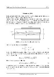
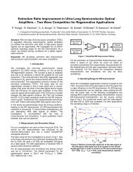
Fig. 1 shows a conceptual setup <strong>for</strong> the <strong>in</strong>vestigations. To keep<br />
the <strong>in</strong>fluence of the bandpass filter after the UL-SOA on the ER<br />
improvement as small as possible, a s<strong>in</strong>e-modulated cont<strong>in</strong>uouswave<br />
(CW) signal was used as a data signal. The <strong>in</strong>vestigated<br />
device is an 8-mm-long bulk SOA. For all measurements and<br />
1041-1135/$25.00 © 2009 IEEE<br />
Authorized licensed use limited to: IEEE Xplore. Downloaded on January 29, 2009 at 05:45 from IEEE Xplore. Restrictions apply.
RUNGE et al.: OPERATIONAL CONDITIONS FOR ER IMPROVEMENT IN UL-SOAs 107<br />
Fig. 1.<br />
Setup used <strong>for</strong> simulations and measurements.<br />
Fig. 3. Output ER <strong>in</strong> dependence of the wavelength detun<strong>in</strong>g, optimized detun<strong>in</strong>g4nm(<br />
=const:; solid l<strong>in</strong>es—measurement; dashed l<strong>in</strong>es—simulation).<br />
Fig. 2. Output ER <strong>in</strong> dependence of the data signal <strong>in</strong>put power (solid<br />
l<strong>in</strong>es—measurement; dashed l<strong>in</strong>es—simulation).<br />
simulations, the driv<strong>in</strong>g current was set to 310 mA/mm. The default<br />
<strong>in</strong>put parameters <strong>for</strong> the experimental series <strong>in</strong> Section IV<br />
are dBm, dB, nm, and<br />
GHz (corresponds to a 40 Gb/s “10101 ”-sequence).<br />
The measured device was fabricated at the He<strong>in</strong>rich-Hertz<br />
Institute and has a buried InGaAsP–InP waveguide structure.<br />
The bandgap wavelength of the active material is 1537 nm. The<br />
conf<strong>in</strong>ement factor of this waveguide is approximately 0.35. To<br />
avoid las<strong>in</strong>g modes, the facets are tilted by 10 and are antireflective<br />
coated.<br />
IV. ER IMPROVEMENT DEPENDENCE ON THE UL-SOA’s<br />
OPERATING CONDITIONS<br />
In this section, the results of the systematic study of the<br />
UL-SOA’s operat<strong>in</strong>g conditions are reported and the experiments<br />
are compared to simulations.<br />
Fig. 2 shows the data signal’s output ER <strong>for</strong> various power<br />
ratios of the CW signal and the data signal. Depend<strong>in</strong>g on the<br />
power ratio an <strong>in</strong>creased output ER compared to the <strong>in</strong>put ER<br />
can be observed. This behavior is unknown from conventional<br />
assumptions and theories. In the follow<strong>in</strong>g <strong>in</strong>vestigations, the<br />
average ER<br />
is used <strong>for</strong> plott<strong>in</strong>g these<br />
characteristics.<br />
The first test series <strong>in</strong>vestigates the ER’s improvement <strong>in</strong> dependence<br />
of the data signal <strong>in</strong>put power (Fig. 2). As a result<br />
there is only a small <strong>in</strong>fluence of the data signal’s <strong>in</strong>put power<br />
on the ER improvement efficiency as long as the power ratio is<br />
readjusted. Furthermore, a qualitative match between the measurements<br />
and the simulations can be seen, as we will observe<br />
it <strong>for</strong> all follow<strong>in</strong>g experimental series.<br />
Another driv<strong>in</strong>g condition of <strong>in</strong>terest is the wavelength detun<strong>in</strong>g.<br />
Fig. 3 shows, that there is an optimized wavelength detun<strong>in</strong>g<br />
around 4 nm.<br />
Fig. 4. ER after pass<strong>in</strong>g the UL-SOA aga<strong>in</strong>st the <strong>in</strong>put ER (ER taken from the<br />
optimized power ratio).<br />
Next the ER improvement <strong>in</strong> dependence of the <strong>in</strong>put ER is<br />
<strong>in</strong>vestigated. With <strong>in</strong>creas<strong>in</strong>g ER at the UL-SOA’s <strong>in</strong>put, the<br />
ER improvement efficiency <strong>in</strong>creases (<strong>in</strong> Fig. 4 slope ). The<br />
discrepancy of the measured ER between Fig. 4 and the other<br />
figures can be ascribed to different setup conditions dur<strong>in</strong>g the<br />
measurements.<br />
So far the studied driv<strong>in</strong>g conditions have only <strong>in</strong>fluenced the<br />
ER improvement efficiency. Driv<strong>in</strong>g conditions that enable and<br />
disable the ER improvement are <strong>in</strong>vestigated <strong>in</strong> the follow<strong>in</strong>g<br />
part of this section and will be <strong>in</strong>terpreted with the help of the<br />
Bogatov-like effect.<br />
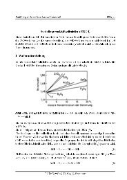
Fig. 5 demonstrates the dependence of the ER improvement<br />
on the polarization. The <strong>in</strong>put signals need to be parallel polarized<br />
<strong>in</strong> order to obta<strong>in</strong> an ER improvement. The polarization dependence<br />
can be expla<strong>in</strong>ed with the Bogatov-like effect. If the<br />
signals are orthogonally polarised, there is no dynamical ga<strong>in</strong><br />
and <strong>in</strong>dex grat<strong>in</strong>g, result<strong>in</strong>g <strong>in</strong> a decreas<strong>in</strong>g ER.<br />
The impact of the signal’s relative wavelength alignment<br />
on the ER improvement is analyzed <strong>in</strong> Fig. 6. Hav<strong>in</strong>g the CW<br />
signal located on the shorter wavelength side, the ER beh<strong>in</strong>d<br />
the UL-SOA is decreased more than it is conventionally expected<br />
(compare to the ER <strong>in</strong> Fig. 5 <strong>for</strong> orthogonal polarized<br />
<strong>in</strong>put signals). The CW signal has to be located on the longer<br />
wavelength side <strong>in</strong> order to obta<strong>in</strong> an ER improvement. This<br />
Authorized licensed use limited to: IEEE Xplore. Downloaded on January 29, 2009 at 05:45 from IEEE Xplore. Restrictions apply.
108 IEEE PHOTONICS TECHNOLOGY LETTERS, VOL. 21, NO. 2, JANUARY 15, 2009<br />
Fig. 5. Measured ER improvement <strong>in</strong> dependence of polarization; both signals<br />
need to be parallel polarized <strong>in</strong> order to create a <strong>in</strong>tensity beat<strong>in</strong>g.<br />
Fig. 7. Simulated ER improvement <strong>in</strong> dependence of the -factor; <strong>in</strong>vert<strong>in</strong>g the<br />
-factor leads to an <strong>in</strong>verse behavior of the TWC (solid l<strong>in</strong>e— < ;<br />
dashed l<strong>in</strong>e— > ).<br />
rameters (signals’ <strong>in</strong>put power, signals’ wavelength detun<strong>in</strong>g<br />
and signals’ <strong>in</strong>put ER) only <strong>in</strong>fluence the ER improvement efficiency.<br />
But there are also driv<strong>in</strong>g conditions (signals’ polarization,<br />
SOA’s -factor and signals’ wavelength alignment) which<br />
can disable the effect. Furthermore, latter driv<strong>in</strong>g conditions <strong>in</strong>dicate<br />
that a Bogatov-like effect <strong>in</strong> the UL-SOA’s saturated section<br />
seems to be the reason <strong>for</strong> the ER improvement. S<strong>in</strong>ce this<br />
effect is caused by the fast <strong>in</strong>traband effects, the regenerative<br />
mechanism should be usable <strong>for</strong> data rates fairly above the carrier<br />
lifetime’s resonance frequency up to several hundred gigabits<br />
per second.<br />
Fig. 6. Relative wavelength alignment of the data signal to the CW signal; the<br />
data signal has to be located on the shorter wavelength side <strong>in</strong> order to achieve<br />
an ER improvement (solid l<strong>in</strong>e—measurement; dashed l<strong>in</strong>e—simulation).<br />
asymmetry regard<strong>in</strong>g the wavelength detun<strong>in</strong>g is a consequence<br />
of the asymmetric probe amplification due to the Bogatov-like<br />
effect as presented <strong>in</strong> [10]. Similar to the ER improvement, the<br />
probe gets amplified <strong>for</strong> an alignment on the pump’s longer<br />
wavelength side while <strong>for</strong> the shorter wavelength side it will be<br />
attenuated.<br />
At the end the dependence of the -factor on the ER improvement<br />
is <strong>in</strong>vestigated (Fig. 7). Invert<strong>in</strong>g the -factor results <strong>in</strong><br />
an <strong>in</strong>verse behavior of the ER development. For this reason,<br />
the alignment of the data signal to the CW signal also has to<br />
be changed <strong>in</strong> order to obta<strong>in</strong> an <strong>in</strong>creas<strong>in</strong>g ER. In the same<br />
manner, the Bogatov-like asymmetry flips over with a negative<br />
-factor. For devices with a decreased -factor like multiple<br />
quantum-well and quantum-dash SOAs the ER improvement<br />
should also be observable. On the one hand, the Bogatov-like<br />
effect should be reduced due to the decreased -factor but on<br />
the other hand CH and SHB are more pronounced <strong>in</strong> such devices.<br />
V. CONCLUSION<br />
We could prove that the ER improvement is a stable process<br />
if the UL-SOA is driven <strong>in</strong> a correct operat<strong>in</strong>g range. Some pa-<br />
REFERENCES<br />
[1] D. Wolfson, A. Kloch, T. Fjelde, C. Janz, B. Dagens, and M. Renaud,<br />
“40 Gb/s all-optical wavelength conversion, regeneration and demultiplex<strong>in</strong>g<br />
<strong>in</strong> an soa-based all-active Mach–Zehnder <strong>in</strong>terferometer,”<br />
IEEE Photon. Technol. Lett., vol. 12, no. 3, pp. 332–334, Mar. 2000.<br />
[2] J. De Merlier, G. Morthier, S. Verstuyft, T. Van Caenegem, I. Moerman,<br />
P. Van Daele, and R. Baets, “Experimental demonstration of all-optical<br />
regeneration us<strong>in</strong>g an MMI-SOA,” IEEE Photon. Technol. Lett., vol.<br />
14, no. 5, pp. 660–662, May 2002.<br />
[3] H. Simos, A. Bogris, and D. Syvridis, “Investigation of a 2R all-optical<br />
regenerator based on four-wave mix<strong>in</strong>g <strong>in</strong> a semiconductor optical amplifier,”<br />
J. Lightw. Technol., vol. 22, no. 2, pp. 595–605, Feb. 2004.<br />
[4] U. Busolt et al., “Two-wave competition <strong>for</strong> all-optical signal process<strong>in</strong>g:<br />
First experimental verification <strong>in</strong> ultra-long SOAs,” <strong>in</strong> ECOC,<br />
Rim<strong>in</strong>i, Italy, 2003, Paper Th3.5.1.<br />
[5] G. Bramann et al., “Two-wave competition <strong>in</strong> ultralong semiconductor<br />
optical amplifiers,” IEEE J. Quantum Electron., vol. 41, no. 10, pp.<br />
1260–1267, Oct. 2005.<br />
[6] P. Runge et al., “<strong>Ext<strong>in</strong>ction</strong> ratio improvement <strong>in</strong> ultra long semiconductor<br />
optical amplifiers—Two wave competition <strong>for</strong> regenerative applications,”<br />
<strong>in</strong> Photonics <strong>in</strong> Switch<strong>in</strong>g, Sapporo, Japan, 2008, Paper<br />
D-05-3.<br />
[7] A. Melo and K. Petermann, “Mach–Zehnder <strong>in</strong>terferometer-based<br />
high-speed OTDM add–drop multiplex<strong>in</strong>g,” J. Lightw. Technol., vol.<br />
25, no. 4, pp. 1017–1026, Apr. 2007.<br />
[8] J. Leuthold, M. Mayer, J. Eckner, G. Guekos, H. Melchior, and Ch.<br />
Zellweger, “Material ga<strong>in</strong> of bulk 1.55 m InGaAsP/InP semiconductor<br />
optical amplifiers approximated by a polynomial model,” J.<br />
Appl. Phys., vol. 87, no. 1, pp. 618–620, 2000.<br />
[9] A. Bogatov, P. Eliseev, and B. Sverdlov, “Anomalous <strong>in</strong>teraction of<br />
spectral modes <strong>in</strong> a semiconductor laser,” IEEE J. Quantum Electron.,<br />
vol. QE-11, no. 7, pp. 510–515, 1975.<br />
[10] A. Uskov, J. Mørk, and J. Mark, “Wave mix<strong>in</strong>g <strong>in</strong> semiconductor laser<br />
amplifiers due to carrier heat<strong>in</strong>g and spectral-hole burn<strong>in</strong>g,” IEEE J.<br />
Quantum Electron., vol. 30, no. 8, pp. 1769–1781, Aug. 1994.<br />
Authorized licensed use limited to: IEEE Xplore. Downloaded on January 29, 2009 at 05:45 from IEEE Xplore. Restrictions apply.