Plane Waves
Plane Waves
Plane Waves

You also want an ePaper? Increase the reach of your titles
YUMPU automatically turns print PDFs into web optimized ePapers that Google loves.
Chapter 3<br />
<strong>Plane</strong> <strong>Waves</strong><br />
This chapter describes the behavior of plane waves at dielectric interfaces, as well as the reflection of plane<br />
waves at multiple layers.<br />
3.1 <strong>Plane</strong> waves at dielectric interfaces<br />
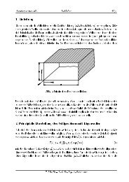
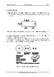
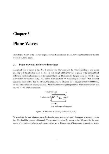
An optical fiber is shown in fig. 3.1. It consists of a fiber core with the refraction index n 1 and a core<br />
cladding with the refraction index n 2 < n 1 . In such an optical fiber the wave is guided by the constant total<br />
reflection. For typical dimensions of the optical fiber ( e.g. fiber diameter 125 µm) there is a reflection e.g.<br />
every millimeter as shown in fig. 3.1. Hence, there are about 10 6 reflexions per kilometer. With assumed<br />
additional losses of less than 0.1 dB/km , the reflectivity per reflection has to be greater than 99, 999998% ,<br />
so that ’total’ reflection is really required. What should the waveguide properties be in order to ensure this<br />
amount of total internal reflection?<br />
6 J = H A B A N E <br />
E ? D J I J H = D <br />
<br />
<br />
) K I > H A E J K C I H E ? D J K C <br />
Figure 3.1: Principle of a waveguide with n 2 < n 1<br />
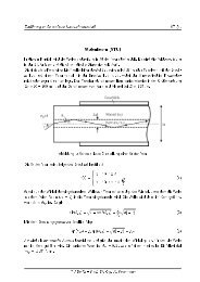
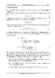
To investigate the total reflection, the reflection of a plane wave at a dielectric boundary, in accordance with<br />
fig. 3.2, should be considered in detail. The vectors ⃗ k 1 , ⃗ k 1 ′ and ⃗ k 2 , shown in fig. 3.2, describe the wave<br />
vector of the incident, reflected and transmitted wave. In this example, ⃗ E is assumed perpendicular to the<br />
1
0<br />
-<br />
0<br />
-<br />
0<br />
O<br />
<br />
<br />
G<br />
<br />
<br />
-<br />
N<br />
Introduction to fiber optic communications ONT/ 2<br />
plane of incidence. Therefore the wave vectors are equal to:<br />
( ) 2 ( ) 2<br />
⃗k1 = ⃗k1<br />
′ = k<br />
2<br />
0 n 2 1 (3.1)<br />
(<br />
⃗k2<br />
) 2<br />
= k<br />
2<br />
0 n 2 2 (3.2)<br />
For example: The vector ⃗ k 1 has an x- and a z-component. Thus:<br />
⎛ ⎞<br />
k x1<br />
⃗ ⎜ ⎟<br />
k1 = ⎝ 0 ⎠ (3.3)<br />
k z with ∣ ⃗ ∣ ∣∣<br />
2<br />
k 1 = k<br />
2<br />
x1 + kz 2 = k0 2n2 1 . Furthermore it is:<br />
cos(θ 1 ) = k z<br />
∣ ⃗ ∣ ∣∣<br />
=<br />
k 1<br />
k z<br />
k 0 n 1<br />
(3.4)<br />
<br />
<br />
<br />
<br />
<br />
<br />
G<br />
<br />
<br />
<br />
The components of the incident wave yield<br />
Figure 3.2: A plane wave incident on a boundary surface<br />
E y = E y1 exp (−j k x1 x − j k z z) (3.5)<br />
H z = E y<br />
sin (θ 1 )<br />
Z F 1<br />
(3.6)<br />
H x = −E y<br />
cos(θ 1 )<br />
Z F 1<br />
(3.7)
Introduction to fiber optic communications ONT/ 3<br />
The characteristic wave impedances on both sides of the interface are<br />
Z F 1 = 1 n 1<br />
√<br />
µ0<br />
ε 0<br />
, Z F 2 = 1 n 2<br />
√<br />
µ0<br />
ε 0<br />
(3.8)<br />
At the interface ( x = 0 ) the tangential field components must be continuous. ⇒ The z-dependent components<br />
of the incident, reflected and transmitted waves have to be equal.<br />
⇒ Hence, the z-components of ⃗ k 1 , ⃗ k 1 ′ and ⃗ k 2 are equal (k z ).<br />
k<br />
For the transmitted wave there is z<br />
| ⃗ = cos(θ k 2|<br />
2) = k z<br />
k 0 n 2<br />
and therefore yields<br />
This is Snell’s law:<br />
k z = k 0 n 1 cos(θ 1 ) = k 0 n 2 cos(θ 2 ) (3.9)<br />
n 1<br />
= cos(θ 2)<br />
n 2 cos(θ 1 ) = sin(φ 2)<br />
sin(φ 1 )<br />
(3.10)<br />
If cos(θ 1 ) > n 2<br />
n 1<br />
or sin(φ 1 ) > n 2<br />
n 1<br />
, there won’t be a real solution in eq. (3.9) for a real angle θ 2 . The wave no<br />
longer penetrates into medium 2. Total reflection occurs. The critical angle for total reflection is:<br />
As long as it is θ 1 < θ 1g and hence φ 1 > φ 1g , total reflection takes place.<br />
sin(φ 1g ) = cos(θ 1g ) = n 2<br />
n 1<br />
(3.11)<br />
3.1.1 Determination of the reflection coefficient for plane waves at dielectric interfaces<br />
The reflection coefficient r E is defined as r E = E y1 ′<br />
E<br />
. The index E of the reflection coefficient r<br />
y1<br />
E<br />
specifies in this case that the E-field is polarized perpendicular to the plane of incidence. The demand for<br />
the continuity of the tangential field components at the interface yields the following boundary conditions<br />
E y1 + E y1 ′ = E y2 (3.12)<br />
H z1 + H z1 ′ = H z2 (3.13)<br />
The indexing 1, 1 ’and 2 refer to the incident, the reflected and the transmitted waves. In both media, wave<br />
impedances are now introduced:<br />
Z 1E = E y1<br />
H z1<br />
= − E y1 ′<br />
H z1 ′<br />
Z 2E = E y2<br />
H z2<br />
=<br />
1<br />
n 2 sin(θ 2 )<br />
1<br />
=<br />
n 1 sin(θ 1 )<br />
√<br />
µ0<br />
ε 0<br />
= k 0<br />
k x1<br />
√<br />
µ0<br />
ε 0<br />
(3.14)<br />
√<br />
µ0<br />
ε 0<br />
= k 0<br />
k x2<br />
√<br />
µ0<br />
ε 0<br />
(3.15)<br />
Now the components of the H-field in eq. (3.13) can be expressed by the components of the E-field. For<br />
that eq. (3.14) and eq. (3.15) have to be inserted into eq. (3.13):<br />
Z 2E<br />
Z 2E<br />
E y1 − E<br />
Z y1 ′ = E<br />
1E Z y2 (3.16)<br />
1E<br />
Inserting this expression into eq. (3.12) and transforming it, the reflection factor r E results in<br />
r E = Z 2E − Z 1E<br />
= n 1 sin(θ 1 ) − n 2 sin(θ 2 )<br />
Z 2E + Z 1E n 1 sin(θ 1 ) + n 2 sin(θ 2 ) = n 1 cos(φ 1 ) − n 2 cos(φ 2 )<br />
n 1 cos(φ 1 ) + n 2 cos(φ 2 )<br />
(3.17)
Introduction to fiber optic communications ONT/ 4<br />
Making use of Snell’s Law (eq. (3.10)) with n 1 = n 2 sin(φ 2 )/ sin(φ 1 ) , eq. (3.17) can be transformed to:<br />
r E = sin(φ 2) cos(φ 1 ) − cos(φ 2 ) sin(φ 1 )<br />
sin(φ 2 ) cos(φ 1 ) + cos(φ 2 ) sin(φ 1 ) = sin(φ 2 − φ 1 )<br />
sin(φ 2 + φ 1 )<br />
(3.18)<br />
In Analogy for a wave with the H-field perpendicular to the incident plane the reflection factor r H can be<br />
determined. Firstly, this result leads to the following field components of the incident wave:<br />
with the characteristic wave impedances<br />
H y = H y1 exp (−j k x1 x − j k z z) (3.19)<br />
E z = −H y · sin (θ 1 ) · Z F 1 (3.20)<br />
E x = H y · cos(θ 1 ) · Z F 1 (3.21)<br />
Z 1H = − E z1<br />
H y1<br />
= E z1 ′<br />
H y1 ′<br />
= sin(θ 1)<br />
n 1<br />
√<br />
µ0<br />
ε 0<br />
=<br />
Z 2H = − E z2<br />
H y2<br />
= sin(θ 2)<br />
n 2<br />
√<br />
µ0<br />
ε 0<br />
=<br />
k x2<br />
n 2 2 · k 0<br />
k x1<br />
√<br />
µ0<br />
ε 0<br />
(3.22)<br />
n 2 1 · k 0<br />
√<br />
µ0<br />
(3.23)<br />
ε 0<br />
With r H = E z1 ′<br />
E z1<br />
= − H y1 ′<br />
H y1<br />
it results:<br />
r H = Z 2H − Z 1H<br />
= n 1 sin(θ 2 ) − n 2 sin(θ 1 )<br />
Z 2H + Z 1H n 1 sin(θ 2 ) + n 2 sin(θ 1 ) = n 1 cos(φ 2 ) − n 2 cos(φ 1 )<br />
n 1 cos(φ 2 ) + n 2 cos(φ 1 )<br />
(3.24)<br />
With Snell’s Law (3.10) eq. (3.24) is redefined to:<br />
r H = cos(φ 2 + φ 1 ) · sin(φ 2 − φ 1 )<br />
cos(φ 2 − φ 1 ) · sin(φ 2 + φ 1 )<br />
(3.25)<br />
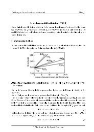
For the given refraction numbers n 1 and n 2 the reflection factors can now be determined as a function of the<br />
incident angle. Fig. 3.3 shows two examples.<br />
In fig. 3.3 the so called Brewster-angle φ 1B is represented, wherein r H = 0 results for the reflexion factor<br />
φ 1 = φ 1B . Corresponding to eq. (3.25), φ 1B results when φ 1 + φ 2 = π/2 . Hence, in this case, the<br />
reflected and transmitted beams are perpendicular to each other. Thus:<br />
The Brewster angle is utilized e.g. for anechoic laser resonators (Fig. 3.4).<br />
For n 1 = 1 (air) it is simply tg(φ 1B ) = n 2 .<br />
tg(φ 1B ) = n 2<br />
n 1<br />
(3.26)<br />
Example: For n 2 = 1.5 the Brewster angle results in φ 1B = 56.3 ◦ . Since only the polarization with ⃗ H<br />
perpendicular to the incident plane penetrates into the gas discharge chamber losslessly, the emitted laser<br />
beam is linearly polarized.<br />
For φ 1 > φ 1g the wave number k x2 = k 0 ·<br />
√<br />
n 2 2 − n2 1 sin2 (φ 1 ) , as well as Z 2H becomes imaginary.<br />
⇒ |r E | = |r H | = 1 (3.27)
Introduction to fiber optic communications ONT/ 5<br />
Figure 3.3: Magnitude of the amplitude reflection coefficients at an interface of glass/air, shown as a function<br />
of the incident angle φ. (a) the incident wave proceeds in air, (b) in glass.<br />
/ = I A J = @ K C I H = K <br />
5 F E A C A <br />
<br />
*<br />
Figure 3.4: Schematic of the laser resonator
N<br />
Introduction to fiber optic communications ONT/ 6<br />
Assuming a total reflection, the field in region 2 (refraction index n 2 ) decreases exponentially with the<br />
penetration depth<br />
d x = 1<br />
j · k x2<br />
=<br />
λ<br />
√<br />
2π n 2 1 sin2 (φ 1 ) − n 2 2<br />
For √ n 2 1 − n2 2 = 0.2 and φ 1 = 90 ◦ , the result is for example d x = 0.8 · λ .<br />
(3.28)<br />
3.2 Reflection on multi layers<br />
The reflection of a plane wave at multiple layers in the x-direction is examined, where each layer has a<br />
different refractive index. m layers each with a refraction number n i ( i = 1...m ) are assumed (fig. 3.5).<br />
<br />
<br />
<br />
<br />
<br />
!<br />
<br />
E<br />
<br />
<br />
@<br />
E<br />
Figure 3.5: m-Layers with the refraction numbers n i and the thicknesses d i<br />
If the incident angle φ 1 is given, the x-component of the wave number in the i-th layer k xi , based on the<br />
constant wave component in z-direction k z = k 0 n 1 sin(φ 1 ) , will be determined as:<br />
k xi = k 0<br />
√n 2 i − n2 1 sin2 (φ 1 ) (3.29)<br />
and the characteristic wave impedances Z iE and Z iH , as shown in eq. (3.14), eq. (3.15), eq. (3.22) and eq.<br />
(3.23), are<br />
Z iE = k 0<br />
k xi<br />
√<br />
µ0<br />
Z iH = k xi<br />
n 2 i k 0<br />
(3.30)<br />
ε 0<br />
√<br />
µ0<br />
. (3.31)<br />
ε 0<br />
Since the wave resistance of the layers can be calculated directly, it is possible to develop an equivalent<br />
electronic circuit (fig. 3.6).<br />
In order to calculate the reflection coefficient at the first layer, the terminating resistor has to be transformed<br />
to the input (e.g. with the Smith chart, see lecture Hochfrequenztechnik I for further details). Hence the<br />
problem is solved in general. A particularly simple and special case is λ 4 -layers.<br />
Accordingly it applies for λ 4 -layers: k xi · d i = π 2<br />
. In this case it is possible to simplify to following<br />
expression:<br />
Z ai =<br />
Z2 iE<br />
Z a(i+1)<br />
(3.32)
Introduction to fiber optic communications ONT/ 7<br />
<br />
-<br />
<br />
-<br />
<br />
N<br />
<br />
E -<br />
<br />
N E<br />
<br />
-<br />
<br />
N <br />
<br />
-<br />
<br />
=<br />
@<br />
E<br />
* A H A ? D K C @ A I 4 A B A N E I B = J H I<br />
E @ E A I A H - > A A<br />
Figure 3.6: equivalent electronic circuit for ⃗ E perpendicular to the incident plane<br />
@<br />
E<br />
F <br />
N E<br />
<br />
<br />
= E<br />
Figure 3.7: equivalent resistance for λ/4-layers<br />
to transform step-by-step the resistance Z a(i+1) a layer forward to Z ai (fig. 3.7). With multiple λ/4 -layers<br />
this transformation can be applied recursively, leading to Z a . Then the reflection factor can be calculated by<br />
r E = Z a − Z 1E<br />
Z a + Z 1E<br />
. (3.33)<br />
As an example, a dielectric layer can be determined, so that the transition from medium 1 to medium 3 is<br />
completely non-reflective, i.e. the wave couples without reflection into the dielectric with n 3 (fig. 3.8). For<br />
simplicity, a perpendicular wave incidence (φ 1 = 0) is assumed. In this case, the wave impedances are<br />
given as:<br />
Z iE = Z iH = Z F i = 1 n i<br />
√<br />
µ0<br />
ε 0<br />
(3.34)<br />
Z F 2 and Z F 3 are merged to the equivalent impedance Z a .<br />
Z a = Z2 F 2<br />
= n √<br />
3 µ0<br />
Z F 3 n 2 (3.35)<br />
2<br />
ε 0<br />
Hence it results Z a = Z F 1 for r E = r H = 0. And furthermore<br />
Z F 2 = √ Z F 1 · Z F 3 ⇒ n 2 = √ n 1 · n 3 (3.36)<br />
Also the thickness of the layer can be determined, since following relation applies:<br />
d 2 · k x2 = d 2 · k 0 · n 2 = d 2 · n 2<br />
2π<br />
λ<br />
!<br />
= π 2<br />
(3.37)
Introduction to fiber optic communications ONT/ 8<br />
I A H A ? D J A E B = A @ A<br />
A > A A 9 A A<br />
<br />
<br />
<br />
!<br />
@ " <br />
<br />
. <br />
<br />
.<br />
<br />
. !<br />
<br />
=<br />
<br />
.<br />
<br />
. !<br />
* A H A ? D K C @ A I 4 A B A N E I B = J H I<br />
E @ E A I A H - > A A<br />
Figure 3.8: e.g.: λ/4-layer for anti-reflection<br />
Hence the thickness of the layer can be evaluated as<br />
d 2 =<br />
λ<br />
4 · n 2<br />
(3.38)