Equivalent Single-Span Model for Dispersion - Hochfrequenztechnik ...
Equivalent Single-Span Model for Dispersion - Hochfrequenztechnik ...
Equivalent Single-Span Model for Dispersion - Hochfrequenztechnik ...

Create successful ePaper yourself
Turn your PDF publications into a flip-book with our unique Google optimized e-Paper software.
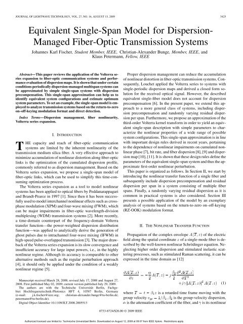
JOURNAL OF LIGHTWAVE TECHNOLOGY, VOL. 27, NO. 16, AUGUST 15, 2009 3425<br />
<strong>Equivalent</strong> <strong>Single</strong>-<strong>Span</strong> <strong>Model</strong> <strong>for</strong> <strong>Dispersion</strong>-<br />
Managed Fiber-Optic Transmission Systems<br />
Johannes Karl Fischer, Student Member, IEEE, Christian-Alexander Bunge, Member, IEEE, and<br />
Klaus Petermann, Fellow, IEEE<br />
Abstract—This paper reviews the application of the Volterra series<br />
expansion to fiber-optic communication systems and per<strong>for</strong>mance<br />
evaluation of dispersion maps. It is shown that under certain<br />
conditions periodically dispersion-managed multispan systems can<br />
be approximated by simple single-span systems with dispersion<br />
precompensation. This single-span approximation can help us to<br />
identify equivalent system configurations and estimate optimum<br />
system parameters. To set an example, the single-span model is employed<br />
to analyze transmission systems based on the return-to-zero<br />
on–off-keying modulation <strong>for</strong>mat and direct detection.<br />
Index Terms—<strong>Dispersion</strong> management, fiber nonlinearity,<br />
Volterra series expansion.<br />
I. INTRODUCTION<br />
T<br />
HE capacity and reach of fiber-optic communication<br />
systems are limited by the inherent nonlinearity of the<br />
transmission medium silica fiber. A very effective approach to<br />
minimize accumulation of nonlinear distortion along fiber-optic<br />
links is the optimization of the cumulated dispersion profile,<br />
commonly referred to as dispersion management. Based on the<br />
Volterra series expansion, we propose a single-span model of<br />
fiber-optic links, which can be used to simplify this time-consuming<br />
optimization process.<br />
The Volterra series expansion as a tool to model nonlinear<br />
systems has been applied to optical fibers by Peddanarappagari<br />
and Brandt-Pearce in 1997 [1]. Since then it has been successfully<br />
used to model interchannel nonlinear effects such as crossphase<br />
modulation (XPM) and four-wave mixing (FWM), which<br />
can be major impairments in fiber-optic wavelength-division<br />
multiplexing (WDM) transmission systems [2]. More recently,<br />
a time-domain counterpart of the frequency-domain Volterra<br />
transfer function—the power-weighted dispersion distribution<br />
function—was applied to analytically derive the generation of<br />
ghost pulses due to intrachannel four-wave mixing (IFWM) in<br />
high-speed pulse-overlapped transmission [3]. The major drawback<br />
of the Volterra series expansion is its slow convergence and<br />
insufficient accuracy <strong>for</strong> large input powers, i.e., in the highly<br />
nonlinear regime. Although its accuracy is comparable to other<br />
alternative methods such as the regular perturbation approach<br />
[4], it should only be applied under the condition of a weakly<br />
nonlinear regime [5].<br />
Proper dispersion management can reduce the accumulation<br />
of nonlinear distortion in fiber-optic transmission systems. Consequently,<br />
Louchet applied the Volterra series to systems with<br />
single-periodic dispersion maps and derived a closed <strong>for</strong>m solution<br />
<strong>for</strong> the received optical signal. However, the described<br />
equivalent single-fiber model does not account <strong>for</strong> dispersion<br />
precompensation [6]. In the present paper, we extend this approach<br />
to a more general class of systems, including dispersion<br />
precompensation and randomly varying residual dispersion<br />
per span. Furthermore, we propose an approximation of the<br />
third-order Volterra kernel trans<strong>for</strong>m in order to yield an equivalent<br />
single-span description with simple parameters to characterize<br />
the nonlinear properties of a wide range of possible<br />
system configurations. This single-span approximation is in line<br />
with important design rules derived in recent years, pertaining<br />
to the dependence of nonlinear impairments on cumulated nonlinear<br />
phase [7], bit rate, and fiber dispersion [8], [9] and dispersion<br />
map [10], [11]. It is shown that these design rules define the<br />
parameters of the equivalent single-span system and thus the approximate<br />
first-order nonlinear perturbation.<br />
This paper is organized as follows. In Section II, we start by<br />
introducing the nonlinear transfer function of a single fiber and<br />
subsequently include dispersion precompensation and residual<br />
dispersion per span in a system consisting of multiple fiber<br />
spans. Finally, a randomly varying residual dispersion as it is<br />
common in practical systems is also considered. Section III<br />
presents a possible application of the model by an exemplary<br />
analysis of systems based on the return-to-zero on–off-keying<br />
(RZ-OOK) modulation <strong>for</strong>mat.<br />
II. THE NONLINEAR TRANSFER FUNCTION<br />
Propagation of the complex envelope of the electric<br />
field along the spatial coordinate of a single-mode fiber is described<br />
by the well-known nonlinear Schrödinger equation. Neglecting<br />
higher order dispersion and stimulated inelastic scattering<br />
processes, such as stimulated Raman scattering, it can be<br />
expressed in the time domain as [12]<br />
Manuscript received March 28, 2008; revised July 17, 2008 and August 27,<br />
2008. First published May 02, 2009; current version published July 29, 2009.<br />
The authors are with the Technische Universität Berlin, Fachgebiet<br />
<strong>Hochfrequenztechnik</strong>-Photonics HFT 4, 10587 Berlin, Germany<br />
(e-mail: j.k.fischer@ieee.org; christian-alexander.bunge@tu-berlin.de;<br />
petermann@tu-berlin.de).<br />
Digital Object Identifier 10.1109/JLT.2008.2005513<br />
where<br />
is a retarded time frame moving with the<br />
group velocity , is the group-velocity dispersion,<br />
is the attenuation coefficient of the fiber, and is its nonlinear<br />
(1)<br />
0733-8724/$26.00 © 2009 IEEE<br />
Authorized licensed use limited to: Technische Universitaet Berlin. Downloaded on August 12, 2009 at 09:07 from IEEE Xplore. Restrictions apply.
3426 JOURNAL OF LIGHTWAVE TECHNOLOGY, VOL. 27, NO. 16, AUGUST 15, 2009<br />
coefficient. In order to derive the frequency-domain Volterra series,<br />
it is practical to trans<strong>for</strong>m (1) into the frequency domain.<br />
The Fourier trans<strong>for</strong>m of (1) is<br />
where is the Fourier trans<strong>for</strong>m of and<br />
<strong>for</strong> brevity. In a weakly nonlinear regime, the complex<br />
envelope can be approximated with the Volterra series<br />
expansion up to third order as [1]<br />
where stands <strong>for</strong> and and<br />
are the first- and third-order Volterra<br />
kernel trans<strong>for</strong>ms, respectively. In the following, we note<br />
<strong>for</strong> conciseness of notation. The<br />
kernel trans<strong>for</strong>ms are determined by substituting (3) into (2).<br />
After some calculations (<strong>for</strong> convenience a detailed derivation<br />
is given in Appendixes I and II), the complex envelope of the<br />
electric field after transmission over fiber sections can be<br />
approximated in the frequency domain as<br />
where is a small perturbation of the linear solution<br />
due to fiber nonlinearity. The nonlinear perturbation can be<br />
expressed through a double convolution as [6]<br />
where<br />
. The nonlinear transfer function<br />
depends on the physical parameters of the transmission<br />
system and is signal independent. For a concatenation of<br />
fiber sections, the nonlinear transfer function can be written in<br />
the following <strong>for</strong>m:<br />
where and are the cumulated gain and dispersion<br />
at the beginning of the mth fiber, and , , and<br />
are the length, group-velocity dispersion, attenuation, and<br />
nonlinear coefficient of the mth fiber, respectively. Please note<br />
that throughout this paper cumulated dispersion in units ps/nm<br />
is denoted by . The relation between this parameter and<br />
in (6) is , with wavelength and the<br />
speed of light . Using this notation and have the same<br />
sign, but has units ps .<br />
The key assumptions <strong>for</strong> (4)–(6) to be valid are as follows.<br />
1) Small signal power and thus small nonlinear perturbation<br />
verifying<br />
, i.e., operation<br />
in a weakly nonlinear transmission regime [1], [5].<br />
(2)<br />
(3)<br />
(4)<br />
(5)<br />
(6)<br />
2) Higher order nonlinear perturbative terms are assumed to<br />
be negligible. This condition may not be fulfilled <strong>for</strong> highspan<br />
counts.<br />
3) Nonlinear interaction between amplifier noise and signal<br />
(e.g., Gordon–Mollenauer phase noise [13]) must be negligible.<br />
This condition may not be fulfilled <strong>for</strong> high-span<br />
counts or systems operating at a low-optical signal-to-noise<br />
ratio (OSNR) and can be problematic when dealing with<br />
phase-modulated signals.<br />
A. <strong>Single</strong>-<strong>Span</strong> System<br />
Assuming a single fiber with length , the nonlinear<br />
transfer function of this fiber is obtained from (6) with<br />
as<br />
where<br />
is its 3 dB bandwidth which is related<br />
through<br />
to the nonlinear diffusion bandwidth derived<br />
in [6]. An analogue expression <strong>for</strong> the single-span kernel<br />
has been derived through averaged propagation models in earlier<br />
contributions by Turitsyn and coworkers [14], [15].<br />
Relating the bandwidth to a measure <strong>for</strong> the spectral width<br />
of the input signal, e.g., to the bit rate as , yields<br />
a dimensionless parameter which is a direct measure <strong>for</strong> the<br />
maximum number of overlapping and nonlinearly interacting<br />
pulses in a single-wavelength channel within the effective length<br />
of a fiber [16]. There<strong>for</strong>e, it universally describes<br />
the strength of intrachannel nonlinear effects. This result was<br />
also obtained empirically by numerical simulations in [9] and<br />
without inclusion of the attenuation coefficient in [8]. Furthermore,<br />
(7) is closely related to the impact of FWM, where<br />
describes the phase mismatch of the interacting fields, and<br />
is the efficiency of the FWM process [17].<br />
Fig. 1 shows the magnitude and phase of the transfer function<br />
as a function of <strong>for</strong> 80 km of nonzero dispersionshifted<br />
fiber (NZDSF) with a dispersion parameter of<br />
ps nm and standard single-mode fiber (SSMF) with<br />
ps nm . Lower local dispersion leads to a broadening<br />
of the transfer function. Consequently, more frequency<br />
components of the input signal participate significantly in the<br />
nonlinear processes affecting the signal at angular frequency .<br />
This reflects the well-known fact that the impact of FWM is<br />
more severe at lower local dispersion [17], [18].<br />
Commonly, a certain amount of dispersion precompensation<br />
is used to predistort the launched signal at the transmitter and<br />
thereby reduce the impact of fiber nonlinearity on the signal<br />
[19], [20]. Assuming linear transmission through the precompensating<br />
fiber, dispersion precompensation can be included in<br />
the single-fiber transfer function through the cumulated dispersion<br />
profile . For a single fiber with precompensation, the<br />
cumulated dispersion is<br />
, where<br />
is the amount of dispersion precompensation in units ps . With<br />
(6), the transfer function of a single fiber preceded by dispersion<br />
precompensation is then<br />
Introducing a precompensation thus only affects the phase of the<br />
nonlinear transfer function and has no effect on its magnitude.<br />
(7)<br />
(8)<br />
Authorized licensed use limited to: Technische Universitaet Berlin. Downloaded on August 12, 2009 at 09:07 from IEEE Xplore. Restrictions apply.
FISCHER et al.: EQUIVALENT SINGLE-SPAN MODEL FOR DISPERSION-MANAGED FIBER-OPTIC TRANSMISSION SYSTEMS 3427<br />
with the nonlinear transfer function of a single fiber according<br />
to (7). Evaluating the geometric series in (10) yields<br />
(11)<br />
with<br />
(12)<br />
Fig. 1. Normalized magnitude and phase of the single-span nonlinear transfer<br />
function (1) <strong>for</strong> L =80km, =0:2dB=km, and (a,b) D =4ps=(nm1<br />
km), i.e., = 9 1 10 rad =s , and (c,d) D = 16 ps=(nm 1 km), i.e.,<br />
=2:25 1 10 rad =s at a wavelength of =1:55 m. Shown are the<br />
exact function according to (23) (circles) and its approximation according to (7)<br />
(line).<br />
For very small arguments of the sine functions, i.e., <strong>for</strong><br />
(11) can finally be approximated as<br />
(13)<br />
(14)<br />
Fig. 2. Profile of the cumulated dispersion in a single-periodic dispersion map<br />
with dispersion precompensation D and residual dispersion per span D .<br />
B. <strong>Single</strong>-Periodic <strong>Dispersion</strong> Maps<br />
A common scheme <strong>for</strong> dispersion management is the singleperiodic<br />
dispersion map [20]. Ideally, it consists of identical<br />
spans, each comprising of a transmission fiber and a dispersion-compensating<br />
fiber (DCF). Depending on the length of the<br />
DCF there is usually a certain amount of residual dispersion per<br />
span. The dispersion profile of such a map is shown in<br />
Fig. 2. Assuming low input power into the DCF and thus negligible<br />
nonlinear impact, they act as ideal lumped dispersion compensation<br />
modules at positions . Under the assumption of<br />
identical spans, the length, attenuation, group-velocity dispersion,<br />
and nonlinear coefficients of the transmission fibers are<br />
the same in each span, and (6) simplifies to [6]<br />
Further simplification is possible by noting that loss is usually<br />
compensated per span (i.e., ) and fibers are relatively<br />
long (i.e., ). Assuming identical spans means that<br />
there is a constant residual dispersion per span . With the<br />
cumulated dispersion at the beginning of the th span<br />
(9) can be written as<br />
(9)<br />
(10)<br />
Essentially, this is the -fold transfer function of a single fiber<br />
with an additional phase shift governed by . In this case,<br />
can be interpreted as the amount of dispersion precompensation<br />
of an equivalent single-span system, which becomes<br />
clear when comparing (14) to (8). Within the validity of the<br />
first-order perturbation approach and (13), systems with arbitrary<br />
single-periodic dispersion maps can thus be described by<br />
simple single-span systems. The per<strong>for</strong>mance of the single-span<br />
system and the -span system will be comparable, provided<br />
that the average launch power is scaled such that the overall<br />
average nonlinear phase shift [7]<br />
(15)<br />
remains constant. However, the boundaries placed by (13) are<br />
quite strict. Should the approximation (14) be at least accurate<br />
<strong>for</strong> , it follows from (13) that .<br />
This means that the cumulated residual dispersion over all spans<br />
has to be much less than the cumulated dispersion over twice the<br />
effective length of the transmission fiber. Extensive numerical<br />
simulations <strong>for</strong> OOK as well as differential phase-shift keying<br />
(DPSK) have shown that the match in terms of required OSNR<br />
penalty is reasonably good <strong>for</strong><br />
, e.g., <strong>for</strong><br />
five spans of SSMF, [21], [22].<br />
Fig. 3(a) shows the magnitude of the nonlinear transfer function<br />
<strong>for</strong> a system with large residual dispersion per span corresponding<br />
to 40 km uncompensated SSMF length. Clearly, the<br />
approximation of the main lobe, even <strong>for</strong><br />
is very<br />
poor. On the other hand, the approximation is quite good <strong>for</strong><br />
small residual dispersion per span as seen in Fig. 3(b).<br />
C. Randomly Varying Residual <strong>Dispersion</strong> per <strong>Span</strong><br />
In practical transmission systems, residual dispersion per<br />
span (RDPS) usually varies from span to span due to a certain<br />
granularity of lumped dispersion-compensating modules<br />
(DCM), e.g., DCM-20 which compensate 20 km of SSMF are<br />
commonly used in 10 Gb/s systems. The model developed in<br />
the preceding section cannot be applied to these systems in<br />
Authorized licensed use limited to: Technische Universitaet Berlin. Downloaded on August 12, 2009 at 09:07 from IEEE Xplore. Restrictions apply.
3428 JOURNAL OF LIGHTWAVE TECHNOLOGY, VOL. 27, NO. 16, AUGUST 15, 2009<br />
Fig. 4. Generic setup of a transmission line consisting of N spans.<br />
Fig. 3. Magnitude of the nonlinear transfer function <strong>for</strong> 10 2 80 km SSMF<br />
without dispersion precompensation and residual dispersion per span corresponding<br />
to (a) 40 km and (b) 2 km of SSMF. The dashed line shows the<br />
magnitude of (1).<br />
a straight<strong>for</strong>ward manner. However, it is possible to find an<br />
approximate solution <strong>for</strong> the nonlinear transfer function of such<br />
systems provided that the RDPS does not differ too much from<br />
its mean value.<br />
Let be the deviation of the RDPS of the ith span from<br />
the mean RDPS , such that .<br />
The cumulated dispersion at the beginning of the nth span can<br />
then be expressed as<br />
(16)<br />
where accounts <strong>for</strong> a possible deviation of the precompensation<br />
from its nominal value. The RDPS mismatch<br />
is uni<strong>for</strong>mly distributed with mean zero and distribution boundaries<br />
defined by the employed DCM. Taking above example<br />
of DCM-20, the maximum mismatch corresponds to 10 km of<br />
SSMF (i.e., ps ps ).<br />
Assuming small deviations<br />
<strong>for</strong> all spans<br />
and validity of (13) <strong>for</strong> , it can be shown that (9)<br />
may be approximated as<br />
(17)<br />
This leads to the same single-span representation as in (14) but<br />
with an equivalent precompensation of<br />
(18)<br />
For the special case of periodic dispersion maps with nonrandom<br />
RDPS, the above equation reduces to the expression<br />
given in (12).<br />
III. NUMERICAL RESULTS AND DISCUSSION<br />
In order to apply the model to transmission of RZ-OOK signals,<br />
a single-span system is simulated numerically with the<br />
commercially available simulation tool VPItransmissionMaker<br />
which implements a split-step Fourier method.<br />
A. System Setup<br />
A general setup of a fiber-optic transmission system is shown<br />
in Fig. 4. The considered modulation <strong>for</strong>mat is RZ-OOK with<br />
a duty cycle of 33% in a single-channel and a five-channel<br />
WDM configuration, where the spectral efficiency of the<br />
WDM configuration is 0.4 bit/s/Hz. The transmitted data are<br />
de Bruijn binary sequences of length . Multiplexer and<br />
demultiplexer filters are modeled as second-order Gaussian<br />
bandpass filters with a 3-dB bandwidth of . A dispersion<br />
precompensation stage after the transmitter is followed by<br />
spans, each consisting of a single-mode fiber (SMF), a<br />
dispersion compensation module (DCM), and an optical amplifier<br />
(OA). For all simulations, the SMF has an attenuation<br />
coefficient of<br />
and a nonlinear coefficient<br />
of<br />
. All simulation results can be scaled<br />
to fibers with other attenuation and nonlinear coefficients by<br />
adjusting the launch power <strong>for</strong> constant nonlinear phase shift<br />
according to (15). Second-order group-velocity dispersion and<br />
the nonlinear impact of the DCM have not been considered.<br />
The optical amplifier compensates the span loss. The postcompensation<br />
stage in front of the receiver is adjusted such that<br />
the net residual dispersion is zero. The electrical filter after<br />
ideal square-law detection of the optical signal is a fifth-order<br />
Bessel low-pass filter with a cutoff frequency of . The<br />
bit-error ratio (BER) is estimated based on a Karhunen–Loève<br />
expansion (assuming additive white Gaussian noise be<strong>for</strong>e the<br />
optical demultiplexer filter) and saddle-point approximation<br />
[23].<br />
B. Nonlinear Threshold of Systems With <strong>Single</strong>-Periodic<br />
<strong>Dispersion</strong> Map<br />
In this section, the per<strong>for</strong>mance of RZ-OOK transmission is<br />
assessed by means of the nonlinear threshold as a criterion. The<br />
nonlinear threshold is defined as the average launch power that<br />
results in an OSNR penalty of 1 dB with respect to the required<br />
back-to-back OSNR <strong>for</strong><br />
. This is a very convenient<br />
measure since it is independent of the bit rate (i.e., the required<br />
back-to-back OSNR), and it ensures that the nonlinear perturbation<br />
is small enough to verify the condition of a weakly<br />
nonlinear regime. Furthermore, it gives the maximum reasonable<br />
launch power into a system, since increasing the launch<br />
power beyond the nonlinear threshold would not yield a higher<br />
OSNR margin at the receiver due to additional nonlinear distortion<br />
of the signal.<br />
Fig. 5 plots the nonlinear threshold <strong>for</strong> single-channel and<br />
WDM transmission versus the parameters and<br />
accounting <strong>for</strong> the type of the transmission fiber and cumulated<br />
dispersion profile, respectively. The lower bound of the abscissa<br />
corresponds to a bit rate of 10 Gb/s and a fiber dispersion of<br />
ps nm , while the upper bound corresponds to<br />
and ps nm . Within the validity range<br />
of the model according to (13), this plot completely describes<br />
Authorized licensed use limited to: Technische Universitaet Berlin. Downloaded on August 12, 2009 at 09:07 from IEEE Xplore. Restrictions apply.
FISCHER et al.: EQUIVALENT SINGLE-SPAN MODEL FOR DISPERSION-MANAGED FIBER-OPTIC TRANSMISSION SYSTEMS 3429<br />
Fig. 6. Nonlinear threshold <strong>for</strong> optimized equivalent precompensation D<br />
in the case of single channel (white circles) and 5 2 B WDM (black circles)<br />
transmission. Due to insufficient bit-sequence length, the nonlinear threshold is<br />
likely to be overestimated in the shaded area, i.e., <strong>for</strong> large channel memory.<br />
Fig. 5. Nonlinear threshold in dBm (contour line labels) <strong>for</strong> RZ-OOK modulation<br />
and transmission of (a) a single channel with the bit rate B or (b) a 52B<br />
WDM signal over a single span with precompensation D . The dots indicate<br />
configurations giving maximum nonlinear threshold <strong>for</strong> B = 40 Gb=s and<br />
D =4; 8; 16 ps=(nm 1 km).<br />
the system per<strong>for</strong>mance <strong>for</strong> an arbitrary bit rate, fiber type and<br />
dispersion map.<br />
For example, the points of maximum nonlinear threshold<br />
<strong>for</strong> a bit rate of 40 Gb/s and a fiber dispersion of<br />
ps nm are indicated by the dots in Fig. 5(a).<br />
With (12) the rule <strong>for</strong> optimum precompensation and residual<br />
dispersion per span derived in [10], [11] can be directly reproduced<br />
(dashed line in Fig. 5). Measurements of the nonlinear<br />
threshold e.g., in [24]–[26] of a simple single-span system can<br />
thus be used to estimate optimum dispersion map parameters<br />
and a lower bound <strong>for</strong> system reach of a certain modulation<br />
<strong>for</strong>mat.<br />
The same approach can be used <strong>for</strong> WDM systems (Fig. 5(b)).<br />
However, the results are valid <strong>for</strong> a fixed number of WDM<br />
channels and fixed spectral efficiency only. Fig. 6 compares the<br />
maximum nonlinear threshold of single-channel transmission<br />
with that of WDM transmission at a spectral efficiency of<br />
0.4 bit/s/Hz. It should be noted that the nonlinear threshold <strong>for</strong><br />
(shaded region) is likely to be overestimated, since<br />
the length of the simulated binary sequence is not sufficient to<br />
correctly account <strong>for</strong> all intrachannel nonlinear distortions [16].<br />
Indeed recent numerical results with sequence lengths up to<br />
indicate that the nonlinear threshold does not increase <strong>for</strong><br />
larger values of [27]. Further note should be taken that<br />
the results represent the nonlinear threshold due to nonlinear<br />
impairments in the absence of net residual dispersion. In certain<br />
scenarios the threshold can be further enhanced by careful<br />
optimization of the net residual dispersion, e.g., in SPM-limited<br />
systems (single-channel transmission at small in Fig. 6)<br />
[28].<br />
The comparison between single-channel and WDM transmission<br />
reveals the severe impact of FWM <strong>for</strong> small ,<br />
where the nonlinear threshold <strong>for</strong> WDM transmission can be<br />
up to 10 dB lower than <strong>for</strong> the single-channel case. In contrast,<br />
there is negligible penalty due to interchannel nonlinear<br />
effects <strong>for</strong> sufficiently large bit rate and/or dispersion<br />
, i.e., in the pseudolinear regime [20]. The maximum nonlinear<br />
threshold is achieved in a tradeoff between inter- and<br />
intrachannel nonlinear effects at<br />
. Assuming<br />
available fiber with a maximum dispersion parameter of<br />
ps nm , e.g., superlarge-effective-area fiber, the system<br />
reach could be maximized with a bit rate of about 20 Gb/s per<br />
channel as this would maximize the nonlinear threshold, while<br />
minimizing the required received OSNR under the given constraints.<br />
A similar analysis <strong>for</strong> binary and quaternary DPSK<br />
modulation can be found in [29].<br />
C. Randomly Varying Residual <strong>Dispersion</strong> per <strong>Span</strong><br />
Due to length variations of the transmission fiber in each span<br />
and granularity of DCM, the nominal RDPS can usually not be<br />
guaranteed throughout a link. There<strong>for</strong>e, it is important to estimate<br />
the consequences of an imperfect dispersion map on the<br />
transmission per<strong>for</strong>mance [30]. In this example, transmission of<br />
5 40 Gb/s RZ-OOK over a link consisting of 10 spans is considered.<br />
The precompensation is varied from 700 ps/nm<br />
to 300 ps/nm in steps of 100 ps/nm. Two different uni<strong>for</strong>m distributions<br />
of the RDPS are simulated:<br />
1) mean RDPS: , maximum deviation:<br />
(corresponding to a DCM-granularity<br />
of 5 km SSMF),<br />
2) mean RDPS: , maximum deviation<br />
(corresponding to a DCM-granularity<br />
of 10 km SSMF).<br />
For negative precompensation values, a positive mean RDPS<br />
has been assumed and vice versa. This way all dispersion maps<br />
show either a monotonously increasing or decreasing cumulated<br />
dispersion at the beginning of each span. A special case occurs<br />
<strong>for</strong> zero precompensation, where the mean RDPS is assumed to<br />
be zero. The equivalent precompensation is determined by<br />
(16) and (18). For each of the two distributions, 1100 random<br />
systems have been simulated. Fig. 7 plots the OSNR penalty<br />
with respect to the required back-to-back OSNR versus precompensation<br />
of the equivalent single-span system. Penalties<br />
Authorized licensed use limited to: Technische Universitaet Berlin. Downloaded on August 12, 2009 at 09:07 from IEEE Xplore. Restrictions apply.
3430 JOURNAL OF LIGHTWAVE TECHNOLOGY, VOL. 27, NO. 16, AUGUST 15, 2009<br />
then applied to obtain optimum system parameters in the case<br />
of RZ-OOK modulation, arbitrary bit rate, and fiber type. The<br />
results indicate that without optimized net residual dispersion<br />
at the receiver, the system reach of WDM transmission with<br />
RZ-OOK modulation and a spectral efficiency of 0.4 bit/s/Hz<br />
can be maximized by using a bit rate of 20 Gb/s per channel<br />
and a superlarge-effective-area fiber with a dispersion parameter<br />
ps nm . Furthermore, it was shown that<br />
the prediction of optimum system parameters by use of the<br />
single-span model even holds in the presence of small random<br />
variations of the residual dispersion per span. This is important<br />
since these variations inevitably occur in practical systems due<br />
to a given granularity of commercially available dispersion<br />
compensating modules.<br />
Fig. 7.<br />
OSNR penalty <strong>for</strong> different values of equivalent precompensation.<br />
Shown are the results of split-step Fourier simulations <strong>for</strong> transmission of 5 2<br />
40 Gb/s RZ-OOK over different transmission lines: a single 80 km span with<br />
launch power of 12 dBm per channel (circles), and 10 2 80 km SSMF with<br />
uni<strong>for</strong>mly distributed residual dispersion per span, varying precompensation<br />
and 2 dBm launch power per channel (dots). The distribution parameters<br />
are: (a) a mean of hD i = 640 ps=nm and a maximum deviation of<br />
1D = 640 ps=nm and (b) a mean of hD i = 680 ps=nm and a<br />
maximum deviation of 1D = 680 ps=nm.<br />
APPENDIX I<br />
THE NONLINEAR TRANSFER FUNCTION OF A SINGLE FIBER<br />
Substituting (3) into (2), discarding all terms of higher order<br />
than 3 and comparing the terms of equal order yields two differential<br />
equations <strong>for</strong> the Volterra kernel trans<strong>for</strong>ms<br />
and<br />
[1]. They are solved by<br />
and<br />
(19)<br />
(20)<br />
<strong>for</strong> the equivalent single-span system (where )<br />
are shown as a reference (circles). As long as mean RDPS and<br />
RDPS variation are small enough, the qualitative match between<br />
the single-span system and random multispan systems is satisfactory<br />
(Fig. 7(a)). For equivalent precompensation in the range<br />
the maximum error in<br />
OSNR penalty is less than 0.5 dB. Also, the optimum system<br />
configuration around a precompensation of about 200 ps/nm<br />
is correctly estimated by the single-span system. However, <strong>for</strong><br />
larger mean RDPS and larger variation per span (Fig. 7(b)) approximation<br />
by the single-span model becomes too inaccurate<br />
and the error in terms of OSNR penalty can approach 1 dB even<br />
near the predicted optimum. The results in Fig. 7(b) also indicate<br />
that the OSNR margin can be significantly reduced due to<br />
DCM granularity, even when special care is taken to match the<br />
optimum dispersion map as accurate as possible.<br />
IV. CONCLUSION<br />
The frequency-domain Volterra series expansion has been<br />
reviewed in the context of dispersion map evaluation. Starting<br />
from the Volterra transfer function of a concatenation of fiber<br />
sections, an approximate solution <strong>for</strong> single-periodic dispersion-managed<br />
systems with precompensation and randomly<br />
varying residual dispersion per span has been derived. In<br />
this context, it was shown that under certain conditions an<br />
arbitrary multispan system can be approximated by a simple<br />
equivalent single-span system, where the precompensation of<br />
the single-span system is defined through the dispersion map<br />
parameters of the multispan system. This simplified model was<br />
where<br />
. With (3), (19), and (20) the<br />
field envelope after propagation is<br />
where<br />
(21)<br />
(22)<br />
is a small perturbation accounting <strong>for</strong> the impact of fiber nonlinearity<br />
on the signal [6]. Examination of (21) reveals a serious<br />
energy-divergence problem when the energy contained in the<br />
nonlinear perturbation gets too large. There<strong>for</strong>e, (21) is valid in<br />
a weakly nonlinear regime only. This is covered in a greater detail<br />
in [5]. However, in the scope of this analysis, the nonlinear<br />
distortions are assumed small enough, such that the condition<br />
of a weakly nonlinear regime is fulfilled.<br />
There are two distinct contributions to the nonlinear perturbation<br />
in (22), one stemming from the physical parameters of the<br />
fiber and the other from the input signal . Thus, it makes sense<br />
to define a nonlinear transfer function to describe the signal-independent<br />
part of the nonlinear perturbation. With the nonlinear<br />
transfer function<br />
(23)<br />
Authorized licensed use limited to: Technische Universitaet Berlin. Downloaded on August 12, 2009 at 09:07 from IEEE Xplore. Restrictions apply.
FISCHER et al.: EQUIVALENT SINGLE-SPAN MODEL FOR DISPERSION-MANAGED FIBER-OPTIC TRANSMISSION SYSTEMS 3431<br />
The nonlinear perturbation can be concisely written as<br />
(24)<br />
For spatial coordinate , the nonlinear transfer function<br />
can be approximated to be independent of and reduces<br />
to as in (7).<br />
APPENDIX II<br />
THE NONLINEAR TRANSFER FUNCTION OF<br />
MULTIPLE FIBER SECTIONS<br />
Practical fiber-optic transmission systems consist of several<br />
concatenated fiber sections. The physical parameters of the<br />
fibers, such as length, group-velocity dispersion, attenuation<br />
and nonlinear coefficient are likely to be different in each<br />
section. Furthermore, the signal has to be amplified in certain<br />
intervals. This can either be done between fiber sections with<br />
discrete amplifiers such as e.g., erbium-doped fiber amplifiers<br />
(EDFA) or distributed along the fiber using a Raman amplification<br />
scheme [31]. Peddanarappagari and Brandt-Pearce derived<br />
a solution <strong>for</strong> the field envelope after transmission over several<br />
fiber sections including lumped amplifiers and amplifier noise<br />
in [32]. However, due to its complexity it is quite unwieldy<br />
and does not lend itself easily to analytic examination. In the<br />
following derivation amplifier noise and consequently any<br />
nonlinear interaction between the signal and amplifier noise are<br />
not considered.<br />
To derive the nonlinear transfer function of a system consisting<br />
of multiple-fiber sections and amplifiers, including different<br />
amplification and dispersion compensation schemes, it is<br />
useful to define gain and dispersion profiles of the transmission<br />
link [6]. The gain profile can be defined as<br />
(25)<br />
where is the accumulated gain, accounts <strong>for</strong> distributed<br />
amplification, is the gain of lumped amplifiers positioned<br />
at and is Dirac’s delta function. Similarly, the<br />
dispersion profile can be defined as<br />
(26)<br />
where is the overall cumulated dispersion at position and<br />
is the cumulated dispersion of a lumped dispersion compensation<br />
module at position .<br />
The field envelope at the output of the th fiber section can<br />
be expressed with the recursion<br />
(27)<br />
where and , , and<br />
are the first-order kernel trans<strong>for</strong>m, the nonlinear transfer function<br />
and the length of the th fiber section, respectively. Please<br />
note that since the nonlinear perturbation generated in each span<br />
is assumed to be very small, it is neglected when calculating<br />
. With (27) the output field envelope after transmission<br />
over fiber sections is<br />
where<br />
(28)<br />
(29)<br />
is the nonlinear perturbation generated in the th fiber section<br />
with , , and the length and nonlinear<br />
coefficient of the th fiber and gain and dispersion profiles<br />
and as defined in (25) and (26). To get a similar<br />
notation as in the single-fiber case, the overall nonlinear perturbation<br />
can be noted as<br />
(30)<br />
with the overall nonlinear transfer function of a concatenation<br />
of fiber sections<br />
(31)<br />
It is easily verified that (23) is a special case of the above<br />
equation with , no dispersion precompensation and no<br />
distributed amplification. Further simplification is possible by<br />
noting that the product of first-order kernel trans<strong>for</strong>ms in (28)<br />
essentially describes the residual gain and dispersion<br />
at the receiver. The overall first-order kernel trans<strong>for</strong>m<br />
of the transmission line can thus be defined as<br />
(32)<br />
Analogous to the solution <strong>for</strong> a single fiber in (21) and (28) can<br />
now be written as<br />
(33)<br />
REFERENCES<br />
[1] K. V. Peddanarappagari and M. Brandt-Pearce, “Volterra series transfer<br />
function of single-mode fibers,” J. Lightw. Technol., vol. 15, no. 12, pp.<br />
2232–2241, Dec. 1997.<br />
[2] B. Xu and M. Brandt-Pearce, “Comparison of FWM- and XPM-induced<br />
crosstalk using the Volterra series transfer function method,” J.<br />
Lightw. Technol., vol. 21, no. 1, pp. 40–53, Jan. 2003.<br />
[3] X. Wei, “Power-weighted dispersion distribution function <strong>for</strong> characterizing<br />
nonlinear properties of long-haul optical transmission links,”<br />
Opt. Lett., vol. 31, no. 17, pp. 2544–2546, Sep. 2006.<br />
[4] A. Vannucci, P. Serena, and A. Bononi, “The RP method: A new tool<br />
<strong>for</strong> the iterative solution of the nonlinear Schrödinger equation,” J.<br />
Lightw. Technol., vol. 20, no. 7, pp. 1102–1112, Jul. 2002.<br />
Authorized licensed use limited to: Technische Universitaet Berlin. Downloaded on August 12, 2009 at 09:07 from IEEE Xplore. Restrictions apply.
3432 JOURNAL OF LIGHTWAVE TECHNOLOGY, VOL. 27, NO. 16, AUGUST 15, 2009<br />
[5] B. Xu and M. Brandt-Pearce, “Modified Volterra series transfer function<br />
method,” IEEE Photon. Technol. Lett., vol. 14, no. 1, pp. 47–49,<br />
Jan. 2002.<br />
[6] H. Louchet, A. Hodžić, K. Petermann, A. Robinson, and R. Epworth,<br />
“Simple criterion <strong>for</strong> the characterization of nonlinear impairments<br />
in dispersion-managed optical transmission systems,” IEEE Photon.<br />
Technol. Lett., vol. 17, no. 10, pp. 2089–2091, Oct. 2005.<br />
[7] J.-C. Antona, S. Bigo, and J.-P. Faure, “Nonlinear cumulated phase as<br />
a criterion to assess per<strong>for</strong>mance of terrestrial WDM systems,” in Proc.<br />
OFC 2002, Anaheim, CA, paper WX5.<br />
[8] B. Konrad and K. Petermann, “Optimum fiber dispersion in high-speed<br />
TDM systems,” IEEE Photon. Technol. Lett., vol. 13, no. 4, pp.<br />
299–301, Apr. 2001.<br />
[9] A. Cauvin, Y. Frignac, and S. Bigo, “Nonlinear impairments at various<br />
bit rates in single-channel dispersion-managed systems,” Electron.<br />
Lett., vol. 39, no. 23, pp. 1670–1671, Nov. 2003.<br />
[10] R. I. Killey, H. J. Thiele, V. Mikhailov, and P. Bayvel, “Reduction of<br />
intrachannel nonlinear distortion in 40-Gb/s-based WDM transmission<br />
over standard fiber,” IEEE Photon. Technol. Lett., vol. 12, no. 12, pp.<br />
1624–1626, Dec. 2000.<br />
[11] Y. Frignac, J.-C. Antona, and S. Bigo, “Enhanced analytical engineering<br />
rule <strong>for</strong> fast optimization of dispersion maps in 40 Gbit/s-based<br />
transmission,” in Proc. OFC 2004, Los Angeles, CA, paper TuN3.<br />
[12] G. P. Agrawal, Nonlinear Fiber Optics, 4th ed. CA: Academic Press,<br />
Dec. 2006.<br />
[13] J. P. Gordon and L. F. Mollenauer, “Phase noise in photonic communications<br />
systems using linear amplifiers,” Opt. Lett., vol. 15, no. 23,<br />
pp. 1351–1353, Dec. 1990.<br />
[14] S. K. Turitsyn, E. G. Turitsyna, S. B. Medvedev, and M. P. Fedoruk,<br />
“Averaged model and integrable limits in nonlinear double-periodic<br />
Hamiltonian systems,” Physical Review E, vol. 61, no. 3, pp.<br />
3127–3132, Mar. 2000.<br />
[15] S. K. Turitsyn, M. P. Fedoruk, E. G. Shapiro, V. K. Mezenrsev, and<br />
E. G. Turitsyna, “Novel approaches to numerical modeling of periodic<br />
dispersion-managed fiber communication systems,” IEEE J. Sel. Topics<br />
Quantum Electron., vol. 6, no. 2, pp. 263–275, Mar./Apr. 2000.<br />
[16] L. K. Wickham, R.-J. Essiambre, A. H. Gnauck, P. J. Winzer, and A. R.<br />
Chraplyvy, “Bit pattern length dependence of intrachannel nonlinearities<br />
in pseudolinear transmission,” IEEE Photon. Technol. Lett., vol.<br />
16, no. 6, pp. 1591–1593, Jun. 2004.<br />
[17] P. Bayvel and R. I. Killey, “Nonlinear optical effects in WDM transmission,”<br />
in Optical Fiber Telecommunications IVB. CA: Academic<br />
Press, 2002, pp. 611–641.<br />
[18] P. J. Winzer and R.-J. Essiambre, “Advanced optical modulation <strong>for</strong>mats,”<br />
Proc. IEEE, vol. 9, no. 5, pp. 952–985, May 2006.<br />
[19] C. Peucheret, N. Hanik, R. Freund, L. Molle, and P. Jeppesen, “Optimization<br />
of pre- and post-dispersion compensation schemes <strong>for</strong><br />
10-Gbits/s NRZ links using standard and dispersion compensating<br />
fibers,” IEEE Photon. Technol. Lett., vol. 12, no. 8, pp. 992–994, Aug.<br />
2000.<br />
[20] R.-J. Essiambre, G. Raybon, and B. Mikkelsen, “Pseudo-linear transmission<br />
of high-speed TDM signals: 40 and 160 Gb/s,” in Optical Fiber<br />
Telecommunications IVB. NJ: Academic Press, 2002, pp. 232–304.<br />
[21] J. K. Fischer, C.-A. Bunge, K. Jamshidi, H. Louchet, and K. Petermann,<br />
“<strong>Equivalent</strong> dispersion maps in fiber-optic communication system,” in<br />
Proc. ECOC 2006, Cannes, France, paper We3.P.134.<br />
[22] J. K. Fischer, C.-A. Bunge, and K. Petermann, “Application of the nonlinear<br />
transfer function to dispersion map evaluation in DPSK transmission<br />
systems,” in Proc. LEOS 2006, Montreal, Canada, paper ThH2.<br />
[23] E. Forestieri, “Evaluating the error probability in lightwave systems<br />
with chromatic dispersion, arbitrary pulse shape and pre- and postdetection<br />
filtering,” J. Lightw. Technol., vol. 18, no. 11, pp. 1493–1503,<br />
Nov. 2000.<br />
[24] R. Dischler, A. Klekamp, J. Lazaro, and W. Idler, “Experimental comparison<br />
of non linear threshold and optimum pre dispersion of 43 Gb/s<br />
ASK and DPSK <strong>for</strong>mats,” in Proc. OFC 2004, Los Angeles, CA, paper<br />
TuF4.<br />
[25] A. Klekamp, R. Dischler, and W. Idler, “Fiber nonlinear threshold comparison<br />
of SMF and NZDSF types on binary 43 Gb/s modulation <strong>for</strong>mats,”<br />
in Proc. ECOC 2005, Glasgow, Scotland, paper We4.P.059.<br />
[26] A. Klekamp, R. Dischler, and W. Idler, “DWDM and single channel<br />
fiber nonlinear thresholds <strong>for</strong> 43 Gb/s ASK and DPSK <strong>for</strong>mats over<br />
various fiber types,” in Proc. OFC 2006, Anaheim, CA, paper OFD5.<br />
[27] P. Serena, A. Orlandini, and A. Bononi, “The memory of optimized dispersion-managed<br />
periodic optical links,” in Proc. ECOC 2007, Berlin,<br />
Germany, paper PO93.<br />
[28] G. Bellotti, A. Bertaina, and S. Bigo, “Dependence of self-phase modulation<br />
impairments on residual dispersion in 10-Gb/s-based terrestrial<br />
transmissions using standard fiber,” IEEE Photon. Technol. Lett., vol.<br />
11, no. 7, pp. 824–826, Jul. 1999.<br />
[29] J. K. Fischer and K. Petermann, “Nonlinear threshold of RZ-DBPSK<br />
and RZ-DQPSK,” in Proc. ECOC 2008, Brussels, Belgium, paper<br />
P.4.19.<br />
[30] C. Xie, L. F. Mollenauer, and N. Mamysheva, “Numerical study of<br />
random variations of span lengths and span path-average dispersions on<br />
dispersion-managed soliton system per<strong>for</strong>mance,” J. Lightw. Technol.,<br />
vol. 21, no. 3, pp. 769–775, Mar. 2003.<br />
[31] G. P. Agrawal, “Optical amplifiers,” in Fiber-Optic Communication<br />
Systems, 3rd ed. NJ: Wiley & Sons, 2002, ch. 6, pp. 226–278.<br />
[32] K. V. Peddanarappagari and M. Brandt-Pearce, “Volterra series approach<br />
<strong>for</strong> optimizing fiber-optic communications system designs,” J.<br />
Lightw. Technol., vol. 16, no. 11, pp. 2046–2055, Nov. 1998.<br />
Johannes Karl Fischer (S’04) was born in Berlin, Germany in 1976. He studied<br />
electrical engineering at the Technische Universität Berlin, Germany and the<br />
University of Manchester, UK. In 2003, he received the Dipl.-Ing. degree in<br />
electrical engineering from the Technische Universität, Berlin. In 2005, he received<br />
a best student paper award of the Asia-Pacific Optical Communications<br />
Conference.<br />
He is currently pursuing his Ph.D. degree at the Technische Universität Berlin.<br />
His research interests are advanced modulation <strong>for</strong>mats and fiber nonlinearity.<br />
Christian-Alexander Bunge (S’01–M’03) received a diploma in electrical engineering<br />
in 1999 and a Ph.D. from the Technische Universität Berlin in 2003.<br />
He studied the propagation and attenuation properties of plastic optical fibers<br />
and of multimode fibers. 2002–2004 he was with the POF-AC of the University<br />
of Applied Sciences in Nuremberg, Germany, as a research fellow and responsible<br />
<strong>for</strong> international projects. Since 2004, he is with the Technische Universität<br />
Berlin as a senior scientist. His current scientific work deals with modelling of<br />
multimode fibers, equalization and optical signal processing.<br />
Klaus Petermann (F’09) was born in Mannheim, Germany in 1951. He<br />
received the Dipl.-Ing. degree in 1974 and the Dr.-Ing. degree in 1976, both<br />
in electrical engineering from the Technische Universität Braunschweig,<br />
Germany. From 1977 to 1983 he was with AEG-Telefunken, Ulm, Germany,<br />
where he was engaged in research work on semiconductor lasers, optical fibers,<br />
and optical fiber sensors. In 1983, he became a full professor at the Technische<br />
Universität Berlin, where his research interests are concerned with optical fiber<br />
communications and integrated optics. In 1993, Dr. Petermann was awarded<br />
with the Leibniz-award from the Deutsche Forschungsgemeinschaft (German<br />
research council). In 1999/2000, he received the “distinguished lecturer”-award<br />
from the IEEE Lasers and Electro-Optics Society.<br />
From 1999–2004, he was an associate editor <strong>for</strong> IEEE PHOTONICS<br />
TECHNOLOGY LETTERS and from 1996–2004 he was a member of the board of<br />
the VDE. From 2004–2006, he was Vice President <strong>for</strong> research at the Technische<br />
Universität Berlin and from 2001–2008 he was member of the Senate of<br />
the Deutsche Forschungsgemeinschaft. Dr. Petermann is a senior member of<br />
the IEEE and a member of the Berlin-Brandenburg academy of science.<br />
Authorized licensed use limited to: Technische Universitaet Berlin. Downloaded on August 12, 2009 at 09:07 from IEEE Xplore. Restrictions apply.