Performance of 40-Gb/s DPSK Demodulator in SOI ... - TU Berlin
Performance of 40-Gb/s DPSK Demodulator in SOI ... - TU Berlin
Performance of 40-Gb/s DPSK Demodulator in SOI ... - TU Berlin

Create successful ePaper yourself
Turn your PDF publications into a flip-book with our unique Google optimized e-Paper software.
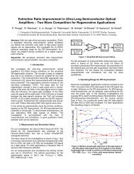
614 IEEE PHOTONICS TECHNOLOGY LETTERS, VOL. 20, NO. 8, APRIL 15, 2008<br />
<strong>Performance</strong> <strong>of</strong> <strong>40</strong>-<strong>Gb</strong>/s <strong>DPSK</strong> <strong>Demodulator</strong><br />
<strong>in</strong> <strong>SOI</strong>-Technology<br />
Karsten Voigt, Lars Zimmermann, Member, IEEE, Georg W<strong>in</strong>zer, Torsten Mitze, Jürgen Bruns, Member, IEEE,<br />
Klaus Petermann, Senior Member, IEEE, Bernd Hüttl, and Colja Schubert<br />
Abstract—A silicon-on-<strong>in</strong>sulator delay <strong>in</strong>terferometer manufactured<br />
<strong>in</strong> 4-m rib waveguide technology is presented. The<br />
polarization-dependent frequency shift is tuned to a value as<br />
low as 0.4 GHz. Cont<strong>in</strong>uous-wave device performance and<br />
polarization-<strong>in</strong>dependent differential phase-shift key<strong>in</strong>g demodulation<br />
performance <strong>in</strong> a <strong>40</strong>-<strong>Gb</strong>/s testbed are demonstrated.<br />
Index Terms—Demodulation, differential phase-shift key<strong>in</strong>g<br />
(<strong>DPSK</strong>), rib waveguide, silicon-on-<strong>in</strong>sulator (<strong>SOI</strong>) technology.<br />
I. INTRODUCTION<br />
FOR upgrades <strong>of</strong> present fiber-optical communication systems<br />
to <strong>40</strong>-<strong>Gb</strong>/s differential phase-shift key<strong>in</strong>g (<strong>DPSK</strong>),<br />
component manufacturers seek <strong>in</strong>tegrated solutions at the<br />
receiver side to reduce footpr<strong>in</strong>t, and component costs. The<br />
development <strong>of</strong> <strong>in</strong>tegrated receivers has been hampered much<br />
by the str<strong>in</strong>gent specifications on polarization-dependent<br />
frequency (PDF) shift related to the birefr<strong>in</strong>gence <strong>of</strong> the<br />
waveguides. Conventional silica technologies <strong>of</strong>fer control<br />
<strong>of</strong> waveguide birefr<strong>in</strong>gence down to , while <strong>DPSK</strong><br />
receivers require approximately birefr<strong>in</strong>gence control.<br />
To achieve such small PDF shifts, these technologies use stress<br />
release grooves [1] or half-wave plates [2], and report best PDF<br />
shifts <strong>of</strong> approximately 1 GHz.<br />
<strong>DPSK</strong> demodulation requires a small relative PDF shift, i.e.,<br />
a tun<strong>in</strong>g <strong>of</strong> the shift between adjacent filter curves. In silicon-on<strong>in</strong>sulator<br />
(<strong>SOI</strong>) rib waveguides, birefr<strong>in</strong>gence arises due to the<br />
geometry <strong>of</strong> the waveguide, and due to mechanical stress <strong>in</strong> the<br />
structure. To this extent, <strong>in</strong>tegrated optics based on mediumsized<br />
<strong>SOI</strong> rib waveguides <strong>of</strong>fers a technological advantage compared<br />
to silica technologies. S<strong>in</strong>ce the PDF shift <strong>in</strong> medium-size<br />
rib waveguides results to an approximately equal fraction from<br />
modal and stress <strong>in</strong>duced birefr<strong>in</strong>gence, very precise birefr<strong>in</strong>gence<br />
control is achievable <strong>in</strong> <strong>SOI</strong> technology.<br />
<strong>SOI</strong> technology has already been employed commercially<br />
[3], and this letter demonstrates the technology’s potential for<br />
low-polarization-dependence applications. We shall present<br />
Manuscript received November 12, 2007; revised January 21, 2008. This<br />
work was supported by the German Federal M<strong>in</strong>istry <strong>of</strong> Education and Research<br />
under Grant 01BP561, and by the European Network <strong>of</strong> Excellence (ePIXnet).<br />
K. Voigt, L. Zimmermann, G. W<strong>in</strong>zer, T. Mitze, J. Bruns, and K. Petermann<br />
are with the Technische Universitaet Berl<strong>in</strong>, 10587 Berl<strong>in</strong>, Germany (e-mail:<br />
karsten.voigt@tu-berl<strong>in</strong>.de).<br />
B. Hüttl and C. Schubert are with the Fraunh<strong>of</strong>er Institut für Nachrichtentechnik<br />
(HHI) Berl<strong>in</strong>, 10587 Berl<strong>in</strong>, Germany.<br />
Color versions <strong>of</strong> one or more <strong>of</strong> the figures <strong>in</strong> this letter are available onl<strong>in</strong>e<br />
at http://ieeexplore.ieee.org.<br />
Digital Object Identifier 10.1109/LPT.2008.918909<br />
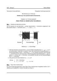
Fig. 1. Layout <strong>of</strong> the DI chip (five DIs plus test structures). Inset shows a 2 2 2<br />
MMI coupler as part <strong>of</strong> one DI.<br />
performance data <strong>of</strong> a <strong>40</strong>-<strong>Gb</strong>/s Mach–Zehnder (MZ) delay<br />
<strong>in</strong>terferometer (DI) device realized <strong>in</strong> 4- m <strong>SOI</strong> waveguide<br />
technology.<br />
The letter will demonstrate that <strong>SOI</strong> waveguide technology<br />
can perform up to state-<strong>of</strong>-the-art <strong>in</strong> <strong>DPSK</strong> demodulation, with<br />
the lowest ever reported PDF shifts <strong>in</strong> <strong>SOI</strong> waveguide technology.<br />
II. DESIGN AND DEVICE TECHNOLOGY<br />
The DI is designed for <strong>40</strong>-<strong>Gb</strong>/s <strong>DPSK</strong> demodulation (i.e.,<br />
a delay <strong>of</strong> 25 ps), which corresponds to a free-spectral range<br />
(FSR) <strong>of</strong> <strong>40</strong> GHz or 320 pm at 1550 nm. The chip area is<br />
25 mm 25 mm, comb<strong>in</strong><strong>in</strong>g five DI devices and some test structures<br />
on a s<strong>in</strong>gle die (see Fig. 1). The devices are fabricated<br />
<strong>in</strong> rib waveguide technology on 4- m commercial bonded and<br />
etched-back substrates. Waveguides are fabricated us<strong>in</strong>g standard<br />
contact lithography and reactive-ion etch<strong>in</strong>g.<br />
The PDF shift <strong>of</strong> the transverse electric (TE) and transverse<br />
magnetic (TM) filter curves <strong>of</strong> the device is caused by the<br />
birefr<strong>in</strong>gence <strong>of</strong> the waveguides. Our measurements determ<strong>in</strong>e<br />
the absolute PDF shift <strong>of</strong> bare waveguides to be about 15 GHz<br />
(120 pm), which is <strong>in</strong> accordance with beam propagation<br />
method simulations. To achieve very small relative PDF shifts,<br />
we developed a birefr<strong>in</strong>gence tun<strong>in</strong>g process, which uses mechanical<br />
stress <strong>in</strong>duced by a cladd<strong>in</strong>g layer (silicon nitride).<br />
The basic mechanism has already been used to m<strong>in</strong>imize the<br />
birefr<strong>in</strong>gence <strong>of</strong> silicon waveguides [4]. However, we use the<br />
effect <strong>in</strong> the opposite direction. In our case, the geometrical<br />
birefr<strong>in</strong>gence and the stress-<strong>in</strong>duced birefr<strong>in</strong>gence have the<br />
same sign. Comb<strong>in</strong><strong>in</strong>g the two, it is possible to reduce the<br />
relative TE/TM shifts down to the required specification <strong>of</strong><br />
about 1 GHz, and better, while the absolute birefr<strong>in</strong>gence <strong>of</strong><br />
the tuned device corresponds to exactly one FSR. More details<br />
concern<strong>in</strong>g chip technology and birefr<strong>in</strong>gence control may be<br />
found elsewhere ([5], [6]).<br />
1041-1135/$25.00 © 2008 IEEE<br />
Authorized licensed use limited to: Technische Universitaet Berl<strong>in</strong>. Downloaded on April 24, 2009 at 09:13 from IEEE Xplore. Restrictions apply.
VOIGT et al.: PERFORMANCE OF <strong>40</strong>-<strong>Gb</strong>/s <strong>DPSK</strong> DEMODULATOR IN <strong>SOI</strong>-TECHNOLOGY 615<br />
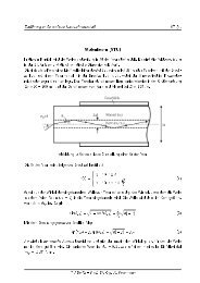
Fig. 4. The <strong>40</strong>-<strong>Gb</strong>/s <strong>DPSK</strong> setup to test the demodulation performance <strong>of</strong> the<br />
<strong>SOI</strong>-DI.<br />
Fig. 2. (a) C-band filter characteristic <strong>of</strong> a <strong>40</strong>-GHz DI on <strong>SOI</strong>. The curve represents<br />
the measurement <strong>in</strong> TM polarization; (b) ext<strong>in</strong>ction ratios (ERs) <strong>of</strong> 90<br />
consecutive measurements with quasi-depolarized light (at 1550 nm).<br />
Fig. 5. Eye diagrams after demodulation <strong>of</strong> <strong>40</strong>-<strong>Gb</strong>/s NRZ/RZ and balanced<br />
detection measurements.<br />
Fig. 3. (a) PDF shift for two temperatures (T =35 C; 70 C); (b) PDL <strong>of</strong><br />
the filter curve maxima for TE and TM mode across C-band; (c) port imbalance<br />
<strong>of</strong> TE/TM light across C-band.<br />
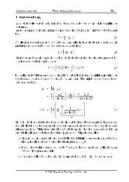
III. EXPERIMENTAL RESULTS<br />
A. Cont<strong>in</strong>uous-Wave Filter Characteristic<br />
The -band transmission characteristics <strong>of</strong> a <strong>40</strong>-GHz DI is<br />
depicted <strong>in</strong> Fig. 2(a) (TM polarization, the filter characteristic<br />
<strong>of</strong> the TE-mode is very similar, and is, therefore, not presented<br />
here). The graph reveals a uniform <strong>in</strong>sertion loss ( 3 dB) as<br />
well as uniform high polarized ext<strong>in</strong>ction ratio across the entire<br />
-band (m<strong>in</strong>imum 28 dB). The signal was taken with respect<br />
to the fiber-to-fiber measurement zero. In Fig. 2(b), we plotted<br />
ext<strong>in</strong>ction ratios <strong>of</strong> 90 consecutive measurements <strong>of</strong> quasi-depolarized<br />
light (dur<strong>in</strong>g the measurement, the Po<strong>in</strong>caré sphere<br />
is scanned with high speed by the polarization controller). The<br />
ext<strong>in</strong>ction ratios spread over a corridor <strong>of</strong> 7 dB, with m<strong>in</strong>imum<br />
ext<strong>in</strong>ction ratio <strong>of</strong> 24 dB.<br />
Fig. 3 depicts the measured PDF shift over the -band (a), the<br />
measured polarization-dependent loss [(PDL), (b)], and the port<br />
imbalance at the two output waveguides (c). The PDF shift never<br />
exceeds 3 pm (0.4 GHz). We observed shifts stay<strong>in</strong>g below<br />
1 GHz also for chip-temperatures up to 70 C [Fig. 3(a)].<br />
These results are comparable to the best values that have been<br />
achieved <strong>in</strong> other technologies ([1], [2], [7], [8]). To our knowledge,<br />
such low PDF shift values are shown for the first time <strong>in</strong><br />
<strong>SOI</strong> waveguide technology. PDL and port imbalance stay below<br />
0.5 dB across the -band. We attribute PDL to imperfections<br />
<strong>of</strong> the multimode <strong>in</strong>terference (MMI) couplers, a problem already<br />
po<strong>in</strong>ted out previously [3]. In general, the <strong>SOI</strong> rib waveguide<br />
technology suffers from the relatively small number <strong>of</strong><br />
supported modes <strong>in</strong> MMI couplers, render<strong>in</strong>g these couplers<br />
more prone to excess loss (the major contribution to our <strong>in</strong>sertion<br />
loss), port imbalance, and PDL. Use <strong>of</strong> higher def<strong>in</strong>ition<br />
lithography and more uniform <strong>SOI</strong> material could partly remedy<br />
that problem, but would also <strong>in</strong>crease fabrication costs.<br />
The small temperature dependence <strong>of</strong> the PDF shift is slightly<br />
counter<strong>in</strong>tuitive. We would expect a larger shift. The temperature<br />
difference <strong>of</strong> 35 K between the two PDF shift measurements<br />
<strong>in</strong> Fig. 3(a) would imply a significant change <strong>in</strong> cladd<strong>in</strong>g<strong>in</strong>duced<br />
stress (deposition temperature 200 C–300 C). The<br />
reason for the observed relatively small additional PDF shift is<br />
presently not understood.<br />
B. Balanced Detection Measurements<br />
To test the system performance <strong>of</strong> the <strong>SOI</strong> <strong>in</strong>terferometer, a<br />
DI device was used to demodulate a <strong>40</strong>-<strong>Gb</strong>/s <strong>DPSK</strong> signal (see<br />
Fig. 4). The signals to drive the modulator were pseudorandom<br />
bit sequences (word length ), amplified <strong>in</strong> high-bandwidth<br />
broadband driver amplifiers. The return-to-zero (RZ) modulation<br />
format was generated with an electroabsorption modulator<br />
(EAM)-based pulse carver (duty cycle <strong>40</strong>%–50%).<br />
The modulated <strong>40</strong>-<strong>Gb</strong>/s signal was amplified, fiber coupled<br />
<strong>in</strong> and out <strong>of</strong> the MZ demodulator, and detected by an <strong>in</strong>tegrated<br />
balanced photodetector (BPD). Fig. 5 shows the eye diagrams<br />
after demodulation and balanced detection, measured<br />
with a digital scope <strong>in</strong>clud<strong>in</strong>g a 70-GHz sampl<strong>in</strong>g head (nonreturn-to-zero<br />
(NRZ) measurement was done without EAM).<br />
For RZ-<strong>DPSK</strong>, the bit-error rate (BER) was measured as<br />
function <strong>of</strong> received power. The result<strong>in</strong>g characteristics have<br />
been plotted <strong>in</strong> Figs. 6 and 7. To demonstrate the dependence<br />
<strong>of</strong> BER performance on PDF shift, we compared two DI devices:<br />
DI-1 (PDF shift: 0.4 GHz), and a device slightly <strong>of</strong>f the<br />
optimum birefr<strong>in</strong>gence, DI-2 (PDF shift: 2.5 GHz). The <strong>in</strong>put<br />
polarization was varied by means <strong>of</strong> a looped-fiber polarization<br />
controller. The state <strong>of</strong> polarization <strong>in</strong> the graphs was labeled<br />
Authorized licensed use limited to: Technische Universitaet Berl<strong>in</strong>. Downloaded on April 24, 2009 at 09:13 from IEEE Xplore. Restrictions apply.
616 IEEE PHOTONICS TECHNOLOGY LETTERS, VOL. 20, NO. 8, APRIL 15, 2008<br />
Fig. 6. Comparison <strong>of</strong> two <strong>SOI</strong> DIs. BER performance for best- and worst-case<br />
<strong>in</strong>put polarization for DI-1 (PDF: 0.4 GHz), and for DI-2 (PDF: 2.5 GHz). The<br />
polarization-dependent penalty was only significant (1 dB) <strong>in</strong> the case <strong>of</strong> DI-2.<br />
The <strong>40</strong>-<strong>Gb</strong>/s <strong>DPSK</strong> measurements show state-<strong>of</strong>-the-art performance.<br />
This demonstrates the high potential <strong>of</strong> <strong>SOI</strong> rib<br />
waveguide technology for low-PDF shift applications. When<br />
compar<strong>in</strong>g <strong>SOI</strong> technology with state-<strong>of</strong>-the-art fiber-based [7]<br />
and free-space devices [8], the follow<strong>in</strong>g differentiators can be<br />
noted: <strong>SOI</strong> <strong>of</strong>fers potentially smaller footpr<strong>in</strong>ts (s<strong>in</strong>gle device<br />
footpr<strong>in</strong>ts, <strong>in</strong>clud<strong>in</strong>g sufficient area for hybrid <strong>in</strong>tegration <strong>of</strong> a<br />
balanced photodiode, are smaller than 25 mm 10 mm), potentially<br />
lower sensitivity to vibrations than free space devices<br />
(due to monolithic planar structure), wafer-level fabrication<br />
technology, <strong>in</strong>tr<strong>in</strong>sically high tun<strong>in</strong>g efficiency ( 10 GHz/K).<br />
Due to the latter, stability problems might be anticipated for<br />
rapid temperature changes. Commercial temperature control<br />
systems stabilize better than 0.01 K. Although we did not<br />
implement advanced temperature control, real applications<br />
might require the use <strong>of</strong> such systems.<br />
Fig. 7. BER performance <strong>of</strong> two types <strong>of</strong> devices: DI-1 <strong>in</strong> <strong>SOI</strong> technology, and<br />
a fiber DI (<strong>40</strong> <strong>Gb</strong>/s). The performance <strong>of</strong> the two technologies is comparable.<br />
best case for optimum BER performance, and worst case for<br />
lowest BER performance.<br />
The measurement <strong>in</strong> Fig. 6 shows a polarization-dependent<br />
penalty <strong>of</strong> 0.1 dB <strong>in</strong> BER performance <strong>in</strong> the case <strong>of</strong> device<br />
DI-1 (small PDF shift). The BER performance <strong>of</strong> DI-2 is slightly<br />
worse due to the residual PDF shift <strong>of</strong> the device. The penalty<br />
<strong>in</strong> BER performance for DI-2 is 1 dB.<br />
Fig. 7 compares the BER performance <strong>of</strong> a <strong>40</strong>-<strong>Gb</strong>/s DI <strong>in</strong><br />
<strong>SOI</strong> technology and a device <strong>in</strong> fiber technology for an arbitrary<br />
<strong>in</strong>put polarization. The two BER curves are virtually <strong>in</strong>dist<strong>in</strong>guishable,<br />
demonstrat<strong>in</strong>g equivalent performance <strong>of</strong> the two<br />
technologies.<br />
IV. SUMMARY AND CONCLUSIONS<br />
The presented <strong>SOI</strong> DI device exhibits across the entire<br />
-band: PDF shifts 0.4 GHz, ext<strong>in</strong>ction ratios substantially<br />
exceed<strong>in</strong>g 20 dB, uniform <strong>in</strong>sertion loss, and low PDL.<br />
REFERENCES<br />
[1] J. Gamet and G. Pandraud, “C- and L-band planar delay <strong>in</strong>terferometer<br />
for <strong>DPSK</strong> decoders,” IEEE Photon. Technol. Lett., vol. 17, no. 6, pp.<br />
1217–1219, Jun. 2005.<br />
[2] C. R. Doerr, D. M. Gill, A. H. Gnauck, L. L. Buhl, P. J. W<strong>in</strong>zer, M.<br />
A. Cappuzzo, A. Wong-Foy, E. Y. Chen, and L. T. Gomez, “Monolithic<br />
demodulator for <strong>40</strong>-<strong>Gb</strong>/s DQPSK us<strong>in</strong>g a star coupler,” J. Lightw.<br />
Technol., vol. 24, no. 1, pp. 171–174, Jan. 2006.<br />
[3] A. House et al., “Silicon waveguide <strong>in</strong>tegrated optical switch<strong>in</strong>g with<br />
microsecond switch<strong>in</strong>g speed,” <strong>in</strong> Proc. OFC 2003, Atlanta, GA, Mar.<br />
2003, vol. 2, pp. 449–450, Paper ThD5.<br />
[4] D.-X. Xu et al., “Elim<strong>in</strong>at<strong>in</strong>g the birefr<strong>in</strong>gence <strong>in</strong> silicon-on-<strong>in</strong>sulator<br />
ridge waveguides by use <strong>of</strong> cladd<strong>in</strong>g stress,” Opt. Lett., vol. 29, no. 20,<br />
pp. 2384–2386, 2004.<br />
[5] L. Zimmermann et al., “Silicon-on-<strong>in</strong>sulator (<strong>SOI</strong>) delay-l<strong>in</strong>e <strong>in</strong>terferometer<br />
with low polarization-dependent frequency shift for <strong>40</strong> <strong>Gb</strong>it/s<br />
<strong>DPSK</strong> demodulation,” <strong>in</strong> Proc. ECOC 2007, Berl<strong>in</strong>, Germany, Sep.<br />
2007, vol. 3, pp. 161–162, Paper We7.3.4.<br />
[6] L. Zimmermann, K. Voigt, G. W<strong>in</strong>zer, J. Bruns, and K. Petermann,<br />
“Optimization considerations for 4 m <strong>SOI</strong>-waveguide technology<br />
with respect to polarization dependence,” <strong>in</strong> Proc. IEEE Int. Conf.<br />
Group IV Photonics, Tokyo, Japan, Sep. 2007, Paper WP43.<br />
[7] Y. K. Lizé et al., “Phase-tunable low-loss, S-, C-, and L-band <strong>DPSK</strong><br />
and DQPSK demodulator,” IEEE Photon. Technol. Lett., vol. 19, no.<br />
23, pp. 1886–1888, Dec. 1, 2007.<br />
[8] X. Liu, Alan, H. Gnauck, X. Wei, J. (Y. C.) Hsieh, C. Ai, and V. Chien,<br />
“Athermal optical demodulator for OC-768 <strong>DPSK</strong> and RZ-<strong>DPSK</strong> signals,”<br />
IEEE Photon. Technol. Lett., vol. 17, no. 12, pp. 2610–2612, Dec.<br />
2005.<br />
Authorized licensed use limited to: Technische Universitaet Berl<strong>in</strong>. Downloaded on April 24, 2009 at 09:13 from IEEE Xplore. Restrictions apply.