BA-UISplus-english-2012 - Hettich AG, CH
BA-UISplus-english-2012 - Hettich AG, CH
BA-UISplus-english-2012 - Hettich AG, CH

Create successful ePaper yourself
Turn your PDF publications into a flip-book with our unique Google optimized e-Paper software.
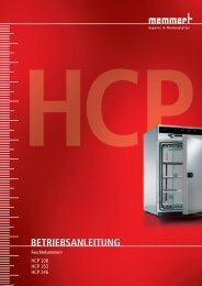
UNPLUS<br />
INPLUS<br />
SNPLUS<br />
UFPLUS<br />
IFPLUS<br />
SFPLUS<br />
OPERATING<br />
INSTRUCTIONS<br />
UNIVERSAL OVEN U<br />
INCU<strong>BA</strong>TOR I<br />
STERILISER S<br />
100% ATMOSAFE. MADE IN GERMANY.<br />
www.memmert.com | www.atmosafe.net
Manufacturer and customer service<br />
MEMMERT GmbH + Co. KG<br />
Postfach 17 20<br />
91107 Schwabach, Germany<br />
Äußere Rittersbacherstr. 38<br />
91126 Schwabach<br />
Germany<br />
Phone: +49 (0)9122 925-0<br />
Fax: +49 (0)9122 14585<br />
E-mail: sales@memmert.com<br />
Internet: www.memmert.com<br />
Customer service:<br />
Service hotline: +49 (0)9171 9792 911<br />
Service fax: +49 (0)9171 9792 979<br />
E-mail:<br />
service@memmert.com<br />
When contacting customer service, always quote the product serial number on the nameplate<br />
(see page 13 ).<br />
Shipping address for repairs:<br />
Memmert GmbH + Co. KG<br />
Kundenservice<br />
Willi-Memmert-Str. 90-96<br />
DE-91186 Büchenbach<br />
Germany<br />
Please contact our customer service before sending appliances for repair or before returning<br />
equipment, otherwise, we have to refuse acceptance of the shipment.<br />
© <strong>2012</strong> MEMMERT GmbH + Co. KG<br />
Date 09/<strong>2012</strong><br />
We reserve the right to make changes
About this manual<br />
About this manual<br />
Purpose and target group<br />
This manual describes the setup, function, transport, operation and maintenance of universal<br />
ovens UN PLUS /UF PLUS , sterilisers SN PLUS /SF PLUS and incubators IN PLUS /IF PLUS . It is intended for use<br />
by trained personnel of the owner, who have the task of operating and/or maintaining the<br />
respective appliance.<br />
If you are asked to work on the appliance, read this manual carefully before starting.<br />
Familiarise yourself with the safety regulations. Only perform work that is described in this<br />
manual. If there is something you do not understand, or certain information is missing, ask<br />
your superior or contact the manufacturer. Do not do anything without authorisation.<br />
Versions<br />
The appliances are available in different configurations and sizes. If specific equipment<br />
features or functions are available only for certain configurations, this is indicated at the<br />
relevant points in this manual.<br />
Due to individual configurations and sizes, illustrations in this manual may be slightly different<br />
from the actual appearance. Function and operation are identical.<br />
Other documents that have to be observed:<br />
► For operation of the appliance with MEMMERT AtmoCONTROL, observe the respective<br />
software manual<br />
► For service and repair (see page 53), please refer to the separate service manual<br />
Storage and forwarding<br />
This instruction manual belongs with the appliance and should always be stored where<br />
persons working on the appliance have access to it. It is the responsibility of the owner to<br />
ensure that persons who are working or will work on the appliance are informed as to the<br />
whereabouts of this instruction manual. We recommend that it is always stored in a protected<br />
location close to the appliance. Make sure that the instruction manual is not damaged by heat<br />
or humidity. If the appliance is sold on or transported and then set up again at a different<br />
location, the operating instructions must go with it.<br />
3
Contents<br />
Contents<br />
1. Safety regulations 6<br />
1.1 Terms and signs used........................................................................................................... 6<br />
1.1.1 Terms used .................................................................................................................... 6<br />
1.1.2 Signs used ...................................................................................................................... 6<br />
1.2 Product safety and dangers ................................................................................................ 7<br />
1.3 Requirements of the operating personnel .......................................................................... 7<br />
1.4 Responsibility of the owner ................................................................................................. 8<br />
1.5 Intended use ........................................................................................................................ 8<br />
1.6 Changes and alterations ...................................................................................................... 9<br />
1.7 Behaviour in case of malfunctions and irregularities .......................................................... 9<br />
1.8 Switching off the appliance in an emergency .................................................................... 9<br />
2. Construction and description 10<br />
2.1 Construction ......................................................................................................................10<br />
2.2 Function .............................................................................................................................11<br />
2.3 Material..............................................................................................................................11<br />
2.4 Electrical equipment ..........................................................................................................11<br />
2.5 Connections and interfaces ...............................................................................................12<br />
2.5.1 Electrical connection ....................................................................................................12<br />
2.5.2 Communication interfaces ..........................................................................................12<br />
2.6 Designation (nameplate)................................................................................................... 13<br />
2.7 Technical data ....................................................................................................................14<br />
2.8 Ambient conditions ...........................................................................................................15<br />
2.9 Scope of delivery ...............................................................................................................16<br />
2.10 Optional accessories ..........................................................................................................16<br />
3. Delivery, transport and setting up 17<br />
3.1 Safety regulations ..............................................................................................................17<br />
3.2 Delivery ..............................................................................................................................17<br />
3.3 Transport ............................................................................................................................17<br />
3.4 Unpacking .........................................................................................................................17<br />
3.4.1 Checking for completeness and transport damage....................................................17<br />
3.4.2 Disposing of packaging material.................................................................................17<br />
3.5 Storage after delivery ........................................................................................................18<br />
3.6 Setting up ..........................................................................................................................18<br />
3.6.1 Installation options ......................................................................................................19<br />
4. Putting into operation 20<br />
4.1 Connecting the appliance .................................................................................................20<br />
4.2 Switching on ......................................................................................................................20<br />
5. Operation and control 21<br />
5.1 Operating personnel..........................................................................................................21<br />
5.2 Opening the door ..............................................................................................................21<br />
5.3 Loading the appliance .......................................................................................................22<br />
5.4 Operating the appliance ....................................................................................................22<br />
5.4.1 ControlCOCKPIT ...........................................................................................................22<br />
5.4.2 Basic operation ............................................................................................................24<br />
5.4.3 Operating modes.........................................................................................................24<br />
5.4.4 Manual mode ..............................................................................................................25<br />
5.4.5 Timer operation ...........................................................................................................26<br />
5.4.6 Programme mode ......................................................................................................27<br />
4
Contents<br />
5.5 Temperature monitoring ..................................................................................................28<br />
5.5.1 Electronic temperature monitoring (TWW) ................................................................29<br />
5.5.2 Electronic temperature limiter (TWB) protection class 2 acc. to DIN 12 880 .............30<br />
5.5.3 Automatic temperature monitor (ASF) ......................................................................31<br />
5.5.4 Mechanical temperature monitoring: Temperature limiter (TB).................................31<br />
5.5.5 Adjusting temperature monitoring .............................................................................31<br />
5.6 Graph .................................................................................................................................33<br />
5.7 Ending operation ...............................................................................................................33<br />
6. Malfunctions, warning and error messages 34<br />
6.1 Warning messages of the monitoring function ................................................................34<br />
6.1.1 Temperature monitoring .............................................................................................34<br />
6.2 Malfunctions, operating problems and appliance errors ................................................35<br />
6.3 Power failure ......................................................................................................................36<br />
7. Menu mode 37<br />
7.1 Overview ............................................................................................................................37<br />
7.2 Basic operation in menu mode using the example of language selection .......................38<br />
7.3 Setup..................................................................................................................................39<br />
7.3.1 Overview ......................................................................................................................39<br />
7.3.2 IP address and subnet mask ........................................................................................39<br />
7.3.3 Unit 40<br />
7.3.4 Temperature monitoring .............................................................................................41<br />
7.3.5 Timer mode .................................................................................................................42<br />
7.3.6 Balance ........................................................................................................................43<br />
7.4 Date and time ....................................................................................................................44<br />
7.5 Adjustment ........................................................................................................................45<br />
7.6 Programme ........................................................................................................................48<br />
7.7 Sound ................................................................................................................................49<br />
7.8 Protocol .............................................................................................................................50<br />
7.9 User ID ...............................................................................................................................51<br />
7.9.1 Description ...................................................................................................................51<br />
7.9.2 User ID activation and deactivation ............................................................................51<br />
8. Sterilisers SF PLUS /SN PLUS 52<br />
8.1 Intended use ......................................................................................................................52<br />
8.2 Note in accordance with Medical Devices Directive ........................................................52<br />
8.3 Guidelines for sterilisation .................................................................................................52<br />
9. Maintenance and service 53<br />
9.1 Cleaning .............................................................................................................................53<br />
9.1.1 Working chamber and metal surfaces ........................................................................53<br />
9.1.2 Plastic parts ..................................................................................................................53<br />
9.1.3 Glass surfaces ..............................................................................................................53<br />
9.2 Regular maintenance.........................................................................................................53<br />
9.3 Repairs and service ............................................................................................................53<br />
10. Storage and disposal 54<br />
10.1 Storage ..............................................................................................................................54<br />
10.2 Disposal .............................................................................................................................54<br />
Index 55<br />
5
Safety regulations<br />
1. Safety regulations<br />
1.1 Terms and signs used<br />
In this manual, certain common terms and signs are used to warn you of danger or to give<br />
you hints that are important in avoiding injury or damage. Observe and follow these hints and<br />
regulations to avoid accidents and damage. These terms and signs are explained below.<br />
1.1.1 Terms used<br />
"Warning"<br />
"Caution"<br />
1.1.2 Signs used<br />
is used whenever you or somebody else could be injured if you do not<br />
observe the accompanying safety regulation.<br />
is used for information that is important for avoiding damage.<br />
Warning signs (warning of a danger)<br />
Danger of<br />
electrocution<br />
Danger of<br />
explosion<br />
Prohibition signs (forbidding an action)<br />
Dangerous<br />
gases / vapours<br />
Danger of burns<br />
Danger of<br />
toppling over<br />
Do not lift Do not tilt Do not enter<br />
Regulation signs (stipulating an action)<br />
Disconnect the<br />
mains plug<br />
Wear gloves<br />
Wear safety<br />
boots<br />
Observe<br />
information<br />
in separate<br />
manual<br />
Other icons<br />
Important or useful additional information<br />
6
Safety regulations<br />
1.2 Product safety and dangers<br />
The appliances described in this manual are technically sophisticated, manufactured using<br />
high-quality materials and subject to many hours of testing in the factory. They contain the<br />
latest technology and comply with recognised technical safety regulations. However, there are<br />
still risks involved, even when the appliances are used as intended. These are described below.<br />
Warning!<br />
After removing covers, live parts may be exposed. You may receive<br />
an electric shock if you touch these parts. Disconnect the mains plug<br />
before removing any covers. Only electrical technicians may work on<br />
the electrical equipment of the appliances.<br />
Warning!<br />
When loading the appliance with an unsuitable load, poisonous<br />
or explosive vapours or gases may be produced. This could cause<br />
the appliance to explode, and people could be severely injured or<br />
poisoned. The appliance may only be loaded with materials/test<br />
objects which do not form any toxic or explosive vapours when<br />
heated up (see also chapter "Intended use" on page 8).<br />
Warning!<br />
Depending on operation, the surfaces in the working chamber<br />
and the chamber load may still be very hot after the appliance is<br />
switched off. Touching these surfaces can cause burns. Wear heatresistant<br />
protective gloves or wait until the appliance cools down.<br />
To do so, pull the handle bar until the door springs open into its<br />
ventilating position (see page 21).<br />
Warning!<br />
In case of appliances of a certain size, you can get accidentally<br />
locked in, which is life-threatening. Do not climb into the appliance!<br />
1.3 Requirements of the operating personnel<br />
The appliance may only be operated and maintained by persons who are of legal age<br />
and have been instructed accordingly. Personnel who are to be trained, instructed or who<br />
are undergoing general training may only work with the appliance under the continuous<br />
supervision of an experienced person.<br />
Repairs may only be performed by qualified electricians. The regulations in the separate service<br />
manual must be observed.<br />
7
Safety regulations<br />
1.4 Responsibility of the owner<br />
The owner of the appliance<br />
► is responsible for the flawless condition of the appliance and for its proper operation in<br />
accordance with its intended use (see page 8);<br />
► is responsible for ensuring that persons who are to operate or service the appliance are<br />
qualified to do this, have been instructed accordingly and are familiar with the operating<br />
instructions at hand;<br />
► must know about the applicable guidelines, requirements and operational safety<br />
regulations, and train staff accordingly;<br />
► is responsible for ensuring that unauthorised persons have no access to the appliance;<br />
► is responsible for ensuring that the maintenance plan is adhered to and that maintenance<br />
work is carried out properly (see page 53);<br />
► has to ensure that the appliance and its surroundings are kept clean and tidy, for example<br />
through corresponding instructions and inspections;<br />
► is responsible for ensuring that personal protective clothing is worn by operating<br />
personnel, e.g. work clothes, safety shoes and protective gloves.<br />
1.5 Intended use<br />
This appliance is exclusively intended for heating up non-explosive substances and objects.<br />
Any other use is improper, and may result in hazards and damage.<br />
The appliance is not explosion-proof (does not comply with the German workplace health &<br />
safety regulation VBG 24). The appliance may only be loaded with materials and substances<br />
which cannot form any toxic or explosive vapours at the set temperature and which cannot<br />
explode, burst or ignite.<br />
The appliance may not be used for drying, vaporising and branding paints or similar materials<br />
the solvents of which could form an explosive mixture when combined with air. If there is<br />
any doubt as to the composition of materials, they must not be loaded into the appliance.<br />
Potentially explosive gas-air mixtures must not form, neither in the working chamber nor in<br />
the direct vicinity of the appliance.<br />
Intended use as a medical device<br />
For appliances subject to the 93/42/EEC guideline (Council Directive on the approximation of<br />
the laws of the Member States relating to medical devices), the intended use is defined as<br />
follows:<br />
► For appliances of the UF PLUS type series: The appliance serves for heating non-sterile cloths<br />
and covers.<br />
► For appliances of the IF PLUS type series: The appliance serves for heating non-sterile cloths<br />
and covers, as well as for temperature control of rinsing and infusion solutions.<br />
► For appliances of the IN PLUS type series: The appliance serves for temperature control of<br />
rinsing and infusion solutions.<br />
► For appliances of the SF PLUS type series: The appliance serves for sterilising medical material<br />
through dry heated air at atmospheric pressure (also see page 52).<br />
8
Safety regulations<br />
1.6 Changes and alterations<br />
No unauthorised changes or alterations may be made to the appliance. No parts may be<br />
added or inserted which have not been approved by the manufacturer.<br />
Unauthorised modifications or changes result in the CE declaration of conformity losing its<br />
validity and the appliance must no longer be operated.<br />
The manufacturer is not liable for any damage, danger or injuries that result from<br />
unauthorised changes or alterations, or from non-observance of the regulations in this<br />
manual.<br />
1.7 Behaviour in case of malfunctions and irregularities<br />
The appliance may only be used in a flawless condition. If you as the operator notice<br />
irregularities, malfunctions or damage, immediately take the appliance out of service and<br />
inform your superior.<br />
You can find information on correcting malfunctions from page 34.<br />
1.8 Switching off the appliance in an emergency<br />
Push the On/Off switch on the control panel<br />
( Fig. 1 ). This disconnects the appliance from<br />
the power supply at all poles.<br />
Warning!<br />
Depending on operation,<br />
the surfaces in the working<br />
chamber and the chamber<br />
load may still be very<br />
hot after the appliance<br />
is switched off. Touching<br />
these surfaces can cause<br />
burns. Wear heat-resistant<br />
protective gloves or wait<br />
until the appliance cools<br />
down. To do so, pull the<br />
handle bar until the door<br />
springs open into its<br />
ventilating position (see<br />
page 21).<br />
Fig. 1<br />
Switch off the appliance by pressing the On/<br />
Off switch<br />
ON<br />
9
Construction and description<br />
2. Construction and description<br />
2.1 Construction<br />
1<br />
2<br />
1<br />
9<br />
8<br />
3<br />
7<br />
4 5 6<br />
Fig. 2 Construction<br />
1 ControlCOCKPIT with capacitive function<br />
keys (see page 23)<br />
2 On/Off switch (see page 20)<br />
3 Working chamber fan (for<br />
UF/IF/SF appliances only)<br />
4 Steel grid<br />
5 Working chamber<br />
6 Nameplate (covered, see page 13)<br />
7 Door handle (see page 21)<br />
8 Turn control with confirmation key<br />
9 USB interface (see page 12)<br />
10
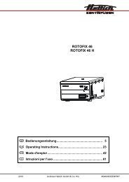
2.2 Function<br />
Appliances of the<br />
UN PLUS , SN PLUS and IN PLUS<br />
type series feature natural<br />
circulation (convection). For<br />
the UF PLUS , SF PLUS and IF PLUS<br />
type series, air is circulated<br />
by a fan at the working<br />
chamber rear panel (Fig. 3 ,<br />
No. 1). It increases the air<br />
flow and provides stronger<br />
horizontal forced air<br />
circulation than natural<br />
convection.<br />
In both the convection and<br />
fan ventilated appliances,<br />
supply air (2) is preheated<br />
in a pre-heating chamber<br />
(3). Through the ventilation<br />
slits in the side panel of<br />
the working chamber, the<br />
preheated air is introduced<br />
into the interior of the<br />
chamber. The supply and<br />
exhaust air (5) volume (air<br />
change) is controlled by the<br />
air flap (4) on the rear panel<br />
of the appliance.<br />
2.3 Material<br />
5<br />
Construction and description<br />
For the outer housing, MEMMERT deploys stainless steel (Mat.No. 1.4016 – ASTM 430)<br />
and for the interior, stainless steel (Mat.No. 1.4301 – ASTM 304) is used, which stands out<br />
through its high stability, optimal hygienic properties and corrosion-resistance towards many<br />
(but not all!) chemical compounds (caution for example with chlorine compounds).<br />
The chamber load for the appliance must be carefully checked for chemical compatibility with<br />
the materials mentioned. A material resistance table can be requested from the manufacturer.<br />
2.4 Electrical equipment<br />
► Operating voltage and current consumption: See nameplate<br />
► Protection class 1, i.e. operating insulation with PE conductor in accordance with EN<br />
61010<br />
► Protection type IP 20 acc. to EN 60 529<br />
► Interference suppression acc. to EN 55011 class B<br />
► Appliance fuse: Fusible link 250 V/15 A quick-blow<br />
► The temperature controller is protected with a miniature fuse 100 mA (200 mA at 115 V)<br />
4<br />
1<br />
3<br />
Fig. 3 Function<br />
1 Fan<br />
2 Fresh air<br />
3 Pre-heating chamber<br />
4 Air flap<br />
5 Exhaust air<br />
2<br />
11
Construction and description<br />
2.5 Connections and interfaces<br />
2.5.1 Electrical connection<br />
This appliance is intended for operation on an electrical power system with a system<br />
impedance Z max<br />
of a maximum of 0.292 ohm at the point of transfer (service line). The<br />
operator must ensure that the appliance is operated only on an electrical power system that<br />
meets these requirements. If necessary, you can ask your local energy supply company what<br />
the system impedance is.<br />
Observe the country-specific regulations when connecting (e.g. in Germany<br />
DIN VDE 0100 with residual current circuit breaker).<br />
2.5.2 Communication interfaces<br />
USB interface<br />
The appliance is fitted by default with a<br />
USB interface in accordance with the USB<br />
specification. This way, you can<br />
► transfer software stored on a USB storage<br />
medium to the appliance (see page 48).<br />
► export protocol logs from the appliance<br />
to a USB storage medium (see page 50).<br />
► transfer user ID data stored on a USB<br />
storage medium to the appliance (see<br />
page 51).<br />
The USB interface is located on the lower right of the ControlCOCKPIT (Fig. 4 ).<br />
Ethernet interface<br />
Via Ethernet interface, the appliance can be<br />
connected to a network, so that you can<br />
transfer programmes created with<br />
AtmoCONTROL software to the appliance<br />
and read out protocol logs. The Ethernet<br />
interface is located on the rear of the<br />
appliance (Fig. 5 ).<br />
For identification purposes, each appliance<br />
connected must have its own unique IP<br />
address. Setting the IP address is described<br />
on page 39.<br />
Fig. 4<br />
Fig. 5<br />
USB interface<br />
Ethernet interface<br />
You will find a description of how to transfer programmes via Ethernet in the<br />
enclosed AtmoCONTROL manual.<br />
With an optional USB to Ethernet converter, the appliance can be directly connected to a<br />
computer / laptop (see Scope of delivery on page 16).<br />
12
Construction and description<br />
2.6 Designation ( nameplate)<br />
The nameplate (Fig. 6) provides information about the appliance model, manufacturer and<br />
technical data. It is attached to the front of the appliance, on the right side behind the door<br />
(see page 10).<br />
1<br />
2<br />
3<br />
4<br />
5<br />
Typ: UN 260 plus F.-Nr.: 0109.0088<br />
230 V~ 14.8 A 50/60 Hz 3400 W<br />
DIN12880-Kl.3.1 Nenntemp.: 300 °C<br />
10<br />
9<br />
8<br />
7<br />
6<br />
Fig. 6 Nameplate (example)<br />
1 Type designation<br />
2 Operating voltage<br />
3 Applied standard<br />
4 Protection type<br />
5 CE conformity<br />
6 Address of manufacturer<br />
7 Disposal note<br />
8 Temperature range<br />
9 Connection / power ratings<br />
10 Appliance number<br />
13
Construction and description<br />
2.7 Technical data<br />
Appliance size 30 55 75 110 160 260 450 750<br />
Appliance width D 1 [mm] 585 585 585 745 745 824 1224 1224<br />
Appliance height E 1 [mm] 707 787 947 867 1107 1186 1247 1726<br />
Appliance depth G 1 (footprint) [mm] 434 514 514 584 584 684 784 784<br />
Depth of door lock [mm] 56<br />
Appliance depth F 1 (including door handle) [mm] 490 570 570 640 640 740 840 840<br />
Working chamber width A 1 [mm] 400 400 400 560 560 640 1040 1040<br />
Working chamber height B 1 [mm] 320 400 560 480 720 800 720 1200<br />
Working chamber depth C 1 [mm] 250 330 330 400 400 500 600 600<br />
Chamber volume [litres] 32 53 74 108 161 256 449 749<br />
Weight [kg] 37 45 51 68 72 91 125 163<br />
Power [W]<br />
Current<br />
consumption [A]<br />
IN/IF 230/115 V 800 1000 1250 1400 1600 1700 1700 1700<br />
UN/UF/SN/SF<br />
IN/IF<br />
UN/UF/SN/SF<br />
230 V 1600 2000 2500 2800 3200 3400 – –<br />
115 V 1100 1400 1700 2000 2200 2200 5800 2 7000 2<br />
400 V – 5800 7000<br />
230 V 3.5 4.3 5.4 6.1 7.0 7.4 7.4 7.4<br />
115 V 7.0 8.7 10.9 12.2 13.9 14.8 14.8 14.8<br />
230 V 7.0 8.7 10.9 12.2 13.9 14.8 – –<br />
115 V 9.6 12.2 14.8 17.4 19.1 19.1 3 x 8.4 2 3 x 10.2 2<br />
400 V – 3 x 8.4 3 x 10.2<br />
max. number of sliding shelves 3 4 6 5 8 9 8 14<br />
max. load per sliding shelve [kg] 30<br />
max. load per appliance [kg] 60 80 120 175 210 300 300 300<br />
Setting temperature<br />
range<br />
Adjustment precision<br />
IN/IF +20 to +80 °C<br />
UN/UF +20 to +300 °C<br />
SN/SF +20 to +250 °C<br />
IN/IF 0.1 K<br />
UN/UF/SN/SF<br />
1<br />
See Fig. 7 on page 15<br />
2<br />
3 x 230 V without zero<br />
up to 100 °C: 0.1 K<br />
above 100 °C: 0.5 K<br />
14
Construction and description<br />
D<br />
56<br />
C<br />
B<br />
E<br />
A<br />
G<br />
F<br />
Fig. 7 Dimensions (see table on page 14)<br />
2.8 Ambient conditions<br />
► The appliance may only be used in enclosed rooms and under the following ambient<br />
conditions:<br />
Ambient temperature +5 ºC to +40 ºC<br />
Humidity rh<br />
max. 80 %, non-condensing<br />
Overvoltage category<br />
II<br />
Pollution degree 2<br />
Altitude of installation<br />
max. 2,000 m above sea level<br />
► The appliance may not be used in areas where there is a risk of explosion. The ambient air<br />
must not contain any explosive dusts, gases, vapours or gas-air mixtures. The appliance is<br />
not explosion-proof.<br />
► Heavy dust production or aggressive vapours in the vicinity of the appliance could lead<br />
to sedimentation in the interior and, as a consequence, could result in short circuits or<br />
damage to electrical parts. For this reason, sufficient measures to prevent large clouds of<br />
dust or aggressive vapours from developing should be taken.<br />
15
Construction and description<br />
2.9 Scope of delivery<br />
► Power cable<br />
► One or two sliding steel grids (load capacity 30 kg each)<br />
► USB storage medium with software and AtmoCONTROL manual<br />
► The operating instructions at hand<br />
► Calibration certificate<br />
► For certain appliance configurations and sizes, the scope of delivery also includes<br />
separately packaged fastening material for wall mounting to protect the appliance from<br />
tipping over (see page 18 )<br />
2.10 Optional accessories<br />
► USB to Ethernet converter (Fig. 8 ). Makes it<br />
possible to connect the appliance's<br />
network interface (see page 12) to the USB<br />
port of a computer / laptop.<br />
► Reinforced, sliding steel grids with a load<br />
capacity of 60 kg each (for appliance size<br />
110 and larger)<br />
Fig. 8<br />
Converter USB to Ethernet<br />
16
3. Delivery, transport and setting up<br />
Delivery, transport and setting up<br />
3.1 Safety regulations<br />
Warning!<br />
You may get your hands or feet squashed when transporting<br />
and installing the appliance. Wear protective gloves and<br />
safety boots.<br />
Warning!<br />
Because of the heavy weight of the appliance, you could injure<br />
yourself if you try to lift it. To carry appliances of the sizes 30 and<br />
55, at least two persons, for appliances of the sizes 75 and 110, four<br />
people are needed. Appliances larger than that may not be carried<br />
but must be transported with a manual pallet jack or forklift truck.<br />
30 55 75 110 160 260 450 750<br />
Warning!<br />
The appliance could fall over and seriously injure you. Never tilt the<br />
appliance and transport it in upright position only.<br />
3.2 Delivery<br />
The appliance is packed in cardboard and is delivered on a wooden palette.<br />
3.3 Transport<br />
The appliance can be transported in three ways:<br />
► With a forklift truck; move the forks of the truck entirely under the pallet<br />
► On a manual pallet jack<br />
► On its own castors, in case of the corresponding configuration, for which the catch on the<br />
(front) castors must be released<br />
3.4 Unpacking<br />
To avoid damage, do not unpack the appliance until you reach the installation site.<br />
Remove the cardboard packaging by pulling it upwards or carefully cutting along an edge.<br />
3.4.1 Checking for completeness and transport damage<br />
► Check the delivery note to ensure that the delivery is complete.<br />
► Check the appliance for damage.<br />
If you notice deviations from the delivery note, damage or irregularities, do not put the<br />
appliance into operation but inform the haulage company and the manufacturer.<br />
3.4.2 Disposing of packaging material<br />
Dispose of the packaging material (cardboard, wood, foil) in accordance with the applicable<br />
disposal regulations for the respective material in your country.<br />
17
Delivery, transport and setting up<br />
3.5 Storage after delivery<br />
If the appliance is first to be stored after delivery: Read the storage conditions from page 54.<br />
3.6 Setting up<br />
Warning!<br />
Due to their centre of gravity, appliances of certain sizes can<br />
fall over to the front and injure you or other people. Separately<br />
packaged fastening material is included in the scope of delivery of<br />
the appliances concerned. After setting up the appliance, use this<br />
fastening material for mounting the appliance's rear side to a wall.<br />
Observe the assembly instructions provided.<br />
The installation site must be flat and horizontal and must be able to reliably bear the weight<br />
of the appliance (see "Technical data" on page 14). Do not place the appliance on a flammable<br />
surface.<br />
Depending on the model (see nameplate), a 230 V, 115 V or 400 V power connection must be<br />
available at the installation site.<br />
The distance between the wall and the rear of the appliance must be at least 15 cm. The<br />
clearance from the ceiling must not be less than 20 cm and the side clearance from walls or<br />
nearby appliances must not be less than 5 cm (Fig. 9). Sufficient air circulation in the vicinity of<br />
the appliance must be guaranteed at all times.<br />
<br />
<br />
Fig. 9<br />
Minimum clearance from walls and ceiling<br />
18
Delivery, transport and setting up<br />
3.6.1 Installation options<br />
Setting up<br />
Floor<br />
Comments<br />
Suitable for appliance size ...<br />
30 55 75 110 160 260 450 750<br />
<br />
Table<br />
Check the load<br />
capacity first<br />
<br />
Stacked<br />
two appliances<br />
maximum; mounting<br />
material (feet)<br />
provided<br />
<br />
Wall<br />
mounting<br />
Base<br />
Separately packaged<br />
fastening material is<br />
included in the scope<br />
of delivery. Observe<br />
the assembly<br />
instructions<br />
provided.<br />
<br />
with/without<br />
castors<br />
<br />
Castor<br />
frame<br />
<br />
Height<br />
adjustable<br />
feet<br />
<br />
19
Putting into operation<br />
4. Putting into operation<br />
Caution:<br />
The first time the appliance is operated, it must not be left unattended until it has reached<br />
the steady state.<br />
4.1 Connecting the appliance<br />
Caution:<br />
Observe the country-specific regulations when<br />
making connections (e.g. in Germany DIN VDE 0100<br />
with residual current circuit breaker). Observe the<br />
connection and power ratings (see nameplate and<br />
"Technical data" on page 14).<br />
Plug the provided power cable into the rear of the<br />
appliance and connect it to the power supply ( Fig. 10 ).<br />
4.2 Switching on<br />
Switch on the appliance by pressing the On/Off switch<br />
on the front of the appliance ( Fig. 11 ).<br />
If the appliance has never been operated before, you<br />
will be prompted to set the operating language, date<br />
and time when you first switch it on. A description of<br />
how to do this is given from page 38. However, to get a<br />
basic overview of operating the appliance, you should<br />
read the following chapter first.<br />
Fig. 10 Connect the power<br />
cable to the rear of the appliance<br />
ON<br />
Fig. 11<br />
Switch on appliance<br />
20
5. Operation and control<br />
Operation and control<br />
Caution:<br />
When loading and operating sterilisers of the SN PLUS /SF PLUS type, make sure to observe the<br />
special notes provided in chapter “Sterilisers SFPLUS/SNPLUS” from page 52.<br />
5.1 Operating personnel<br />
The appliance may only be operated by persons who are of legal age and have been instructed<br />
accordingly. Personnel who are to be trained, instructed or who are undergoing general<br />
training may only work with the appliance under the continuous supervision of an experienced<br />
person.<br />
5.2 Opening the door<br />
► To open the door, pull the handle bar to the side (to the left or to the right, depending on<br />
the door variation, see Fig. 12, A). The door opens slightly, so that the heat can be vented<br />
with the door ajar in case of high temperature inside the chamber. The door can then be<br />
opened completely (B).<br />
► To close the door, push the handle bar back (C).<br />
A<br />
B<br />
C<br />
Fig. 12<br />
Opening and closing the door<br />
Warning!<br />
In case of appliances of a certain size, you can get accidentally<br />
locked in, which is life-threatening. Do not climb into the appliance!<br />
21
Operation and control<br />
5.3 Loading the appliance<br />
Warning!<br />
When loading the appliance with an unsuitable load, poisonous<br />
or explosive vapours or gases may be produced. This could cause<br />
the appliance to explode, and persons could be severely injured or<br />
poisoned. The appliance may only be loaded with materials which do<br />
not form any toxic or explosive vapours when heated up and cannot<br />
ignite (see also “Intended use” on page 8). If there is any doubt as to<br />
the composition of materials, they must not be loaded into the appliance.<br />
Caution:<br />
Check the chamber load for chemical compatibility with the materials of the appliance<br />
(see page 11).<br />
Insert the sliding steel grids or sliding shelves. The maximum number or grids / shelves and the<br />
load capacity are specified in the technical data overview from page 14.<br />
The chamber must not be<br />
loaded too tightly, so that<br />
proper air circulation in the<br />
working chamber is guaranteed.<br />
Do not place any<br />
chamber load on the floor,<br />
touching the side walls or<br />
right below the ceiling of the<br />
working chamber (Fig. 13 , see<br />
also the "correct loading"<br />
sticker on the appliance).<br />
In case of improper loading<br />
(chamber loaded too tightly),<br />
reaching the set temperature<br />
may take longer than normal. Fig. 13 Correct placement of the chamber load<br />
5.4 Operating the appliance<br />
5.4.1 ControlCOCKPIT<br />
In manual operation, the desired parameters are entered at the ControlCOCKPIT on the front<br />
of the appliance (Fig. 14 and Fig. 15 ). You can also make basic settings here (menu). Additionally,<br />
warning messages are displayed, e.g. if the temperature is exceeded. In programme<br />
mode, the parameters defined, the programme description, the programme segment currently<br />
active and programme duration remaining are displayed (for a more detailed description,<br />
see page 27).<br />
22
Operation and control<br />
1 2<br />
3 4 5<br />
13 14 15 16<br />
TEMP<br />
180.4°C<br />
Set 180.4°C<br />
FAN<br />
0 %<br />
LIGHT<br />
ON<br />
LIGHT<br />
100 %<br />
12.Sept.<strong>2012</strong> Fr 20.10.2010 13:44 20:31 off<br />
Manual Holz trocknen Mode<br />
aufheizen<br />
09:12h<br />
TIMER<br />
04h 44h:44m 30m<br />
Ende 23.Nov 14:45 13:30<br />
FLAP<br />
40 20% %<br />
ALARM of °C<br />
GRAPH<br />
min<br />
max<br />
°C<br />
%rh<br />
160.0°C 190.0°C<br />
min<br />
000°C<br />
auto<br />
000°C<br />
auto off<br />
+/- - 5.0 99KK<br />
0 12<br />
ON<br />
6 7 8 9 10<br />
11 12 17 18<br />
19 20<br />
Fig. 14 ControlCOCKPIT for UF PLUS /IF PLUS /SF PLUS appliances in operating mode (width may<br />
differ depending on appliance size)<br />
1 2 5 13<br />
14<br />
15 16<br />
TEMP<br />
180.0 °C<br />
Set 180.9 °C<br />
LIGHT<br />
ON<br />
LIGHT<br />
100 %<br />
12.Sept.<strong>2012</strong> Fr 20.10.2010 13:44 20:31<br />
Manual Holz trocknen Mode<br />
aufheizen<br />
09:12h<br />
off<br />
TIMER<br />
44h:44m 04h 30m<br />
Ende 14:45 23.Nov 13:30<br />
FLAP<br />
40 %<br />
ALARM<br />
min<br />
160.0°C<br />
min<br />
auto<br />
000°C<br />
max<br />
190.0°C 000°C<br />
GRAPH<br />
°C<br />
%rh<br />
auto off<br />
+/- + - 5.0 99KK<br />
0 12<br />
ON<br />
6 7 8 9<br />
10 11 12 17 18 19 20<br />
Fig. 15 ControlCOCKPIT for UN PLUS /IN PLUS /SN PLUS appliances in operating mode (width may<br />
differ depending on appliance size)<br />
1 Activation key for temperature setpoint<br />
adjustment<br />
2 Setpoint and actual temperature display<br />
3 Fan speed display<br />
4 Activation key for fan speed setting<br />
5 Switch to menu mode (see page 37)<br />
6 Activation key for timer setting<br />
7 On/Off switch<br />
8 Timer display<br />
9 Air flap position display<br />
10 Activation key for air flap position adjustment<br />
11 Turn control for setpoint adjustment<br />
12 Confirmation key (accepts setting made<br />
with the turn control)<br />
13 Activation key for interior lighting (additional<br />
option)<br />
14 Interior lighting display (additional option)<br />
15 Appliance state and programme display<br />
16 Activation key for the appliance state<br />
17 Activation key for temperature monitoring<br />
18 Temperature monitoring display<br />
19 Graphic representation<br />
20 Activation key for graphic representation<br />
23
Operation and control<br />
5.4.2 Basic operation<br />
In general, all settings are made according to the following pattern:<br />
1. Activate the desired parameter (e.g. temperature).<br />
To do so, press the corresponding<br />
activation key on the left or right or<br />
the respective display. The activated display<br />
is lined in colour, the other displays<br />
are dimmed. The set value is highlighted<br />
in colour.<br />
TEMP<br />
22.4°C<br />
Set 10037.0°C<br />
.5°C<br />
TIMER<br />
-- h -- m<br />
2. By turning the turn control to the left<br />
TEMP<br />
or right, adjust the set value (e.g. to<br />
180.0 ºC).<br />
22.4°C<br />
Set 180.0°C<br />
3. Save the set value by pressing the confirmation<br />
key.<br />
The display returns to normal and the<br />
appliance begins adjusting to the defined<br />
set value.<br />
TEMP<br />
23.2°C<br />
Set 180.0°C<br />
Additional parameters (air flap position etc.) can be set accordingly.<br />
If no new values are entered or confirmed for approx. 30 seconds, the appliance automatically<br />
returns to the main menu and restores the former values.<br />
If you want to cancel the setting procedure, press<br />
the activation key on the left or right of the display that<br />
you want to exit. The appliance restores the former<br />
values. Only the settings that you have confirmed by<br />
pressing the confirmation key before cancelling the<br />
setting procedure are accepted.<br />
5.4.3 Operating modes<br />
The appliance can be operated in three modes:<br />
► Manual mode: The appliance runs in permanent operation at the values set on the<br />
ControlCOCKPIT. Operation in this mode is described in chapter 5.4.4.<br />
► Timer operation: The appliance runs at the values set until the timer has elapsed. Operation<br />
in this mode is described in chapter 5.4.5 .<br />
► Programme mode: The appliance automatically runs programme sequences which have<br />
been defined using AtmoCONTROL software at a computer / laptop and then transferred<br />
to the appliance from a USB stick or via Ethernet. Operation in this mode is described in<br />
chapter 5.4.6.<br />
T<br />
T<br />
T<br />
-<br />
24
Operation and control<br />
The status display shows you which operating mode or operating state the appliance is<br />
currently in. The current operating state is highlighted in colour and indicated by the text<br />
display:<br />
Appliance is in programme mode<br />
■ Programme is stopped<br />
12.Sept.<strong>2012</strong> 13:44<br />
Appliance is in manual operating mode<br />
Manual Mode<br />
The example on the right shows the appliance in manual<br />
mode, identified by the coloured hand symbol.<br />
5.4.4 Manual mode<br />
In this operating mode, the appliance runs in permanent operation at the values set on the<br />
ControlCOCKPIT.<br />
Adjustment options<br />
As described in chapter 5.4.2 , you can set the following parameters after pressing the corresponding<br />
activation key (in any sequence):<br />
Temperature<br />
Adjustment range: model dependent (see nameplate and technical<br />
date on page 14)<br />
Heating operation is indicated by the symbol.<br />
You can select °C or °F as the temperature unit displayed (see<br />
page 40).<br />
Air flap position<br />
Adjustment range: 0 % (closed, recirculating operation) to 100 %<br />
(completely opened, fresh air operation) in steps of 10 %<br />
TEMP<br />
24.4°C<br />
Set 180.4 °C<br />
FLAP<br />
40 %<br />
Fan speed<br />
(only for UF/IF/SF PLUS appliances)<br />
Adjustment range: 0 to 100 % in steps of 10%<br />
FAN<br />
50 %<br />
Interior lighting (additional option)<br />
Adjustment range: 0 %, 100 %<br />
LIGHT<br />
100 %<br />
25
Operation and control<br />
5.4.5 Timer operation<br />
In timer operation, you can adjust the time the appliance runs at the set value:<br />
1. Press the activation key to the left of<br />
the timer display. The timer display is<br />
activated.<br />
TIMER<br />
00h<br />
00m<br />
Ende 23.11. 09:00<br />
FA<br />
2. Turn the turn control until the desired<br />
duration is displayed – in this example 4<br />
hours 30 minutes. The approximate end<br />
time is shown beneath, in a smaller font.<br />
End<br />
TIMER<br />
04h 30m<br />
23.Nov 13:30<br />
Up to a duration of 23 hours 59 minutes, the time is displayed in hh:mm (hours:minutes)<br />
format. For 24 hours and more, the format dd:hh (days:hours) is used. The maximum<br />
duration adjustable is 99 days 23 hours.<br />
3. Press the confirmation key to confirm.<br />
TIMER<br />
The display now shows the remaining<br />
time in a large font and the approximate<br />
end time in a smaller font beneath.<br />
04h 30m<br />
End 23.Nov 13:30<br />
4. Now, as described under 5.4.2 , set the individual values for temperature, air flap position<br />
etc. which you want the appliance to operate at. For universal ovens UN PLUS /UF PLUS and<br />
incubators IN PLUS /IF PLUS , the set values can be changed while the timer elapses. The changes<br />
are effective immediately. For sterilisers SN PLUS /SF PLUS , parameters cannot be changed while<br />
the timer elapses.<br />
For universal ovens UN PLUS /UF PLUS and incubators IN PLUS /IF PLUS , you can choose if the timer<br />
should run setpoint-dependent or not in the Setup – this determines if the timer should<br />
not start until a tolerance band around the set temperature is reached or if it should start<br />
right after activation (see page 42). If the timer runs setpoint-dependent, this is indicated by<br />
the symbol in the timer display.<br />
When the timer has elapsed, the display shows 00:00. All functions<br />
TIMER<br />
(heating etc.) are switched off. If a fan had been active, it will keep<br />
on running for a short safety period.<br />
To deactivate the timer, open the timer display by pressing the<br />
activation key again and then turning the turn control to reduce<br />
the timer setting until --:-- is displayed. Confirm with the confirmation<br />
key.<br />
00h<br />
00m<br />
End 23.Nov 13:30<br />
TIMER<br />
--h<br />
--m<br />
End 23.Nov 13:30<br />
26
Operation and control<br />
5.4.6 Programme mode<br />
In this operating mode, programmes saved in the appliance can be started with different<br />
combinations of individual parameters (temperature, air flap position, fan speed, working<br />
chamber lighting) at staggered intervals, which the appliance then automatically processes in<br />
sequence. These programmes are not created directly at the appliance but externally at a computer<br />
/ laptop and using AtmoCONTROL software. Transfer to the appliance is possible using<br />
the provided USB storage medium or via Ethernet.<br />
A description of how to create and save programmes can be found in the separate<br />
AtmoCONTROL software manual.<br />
Starting a programme<br />
1. Press the activation key to the right of<br />
the status display. The current operating<br />
mode is highlighted automatically, in this 0 %<br />
example Manual Mode ( ).<br />
0°C<br />
off<br />
13.Sept.<strong>2012</strong><br />
Fr 20.10.2010 20:31 17:44<br />
manueller Manual mode Betrieb<br />
GRAPH<br />
80<br />
40<br />
2. Turn the turn control until the start<br />
symbol is highlighted. The current<br />
programme is displayed, in this example<br />
Test 012.<br />
12.Sept.<strong>2012</strong><br />
Test 012<br />
ready<br />
10:44<br />
Only the programme currently selected in the menu and shown in the display can be<br />
used. If you want to process another programme, you need to activate it in the menu<br />
first (description from page 48 ).<br />
3. To start the programme, press the confirmation<br />
key. The programme starts. The<br />
12.Sept.<strong>2012</strong> 10:44<br />
Test 012<br />
display shows:<br />
Ramp 1<br />
► the programme description (in this example<br />
Test 012)<br />
► the programme segment description, in<br />
this example Ramp 1<br />
► the current run (in case of loops)<br />
You cannot change any parameters (e.g. the temperature) at the appliance while a<br />
programme is running. However, the displays ALARM and GRAPH can still be used.<br />
Cancelling a programme<br />
You can cancel an active programme at any<br />
time.<br />
1. Press the activation key to the right of<br />
the status display. The status display is<br />
automatically highlighted.<br />
0 %<br />
0°C<br />
12.Sept.<strong>2012</strong><br />
Fr 20.10.2010 20:31 10:44<br />
manueller Test 012 Betrieb<br />
Ramp 3<br />
GRAPH<br />
80<br />
27
Operation and control<br />
2. Turn the turn control until the stop symbol<br />
■ is highlighted.<br />
12.Sept.<strong>2012</strong> 10:48<br />
Cancel program<br />
Test 012<br />
3. Press the confirmation key to confirm.<br />
The programme is cancelled.<br />
12.Sept.<strong>2012</strong> 10:49<br />
Program cancelled<br />
Test 012<br />
A cancelled programme cannot be resumed at the point it was cancelled. It must be<br />
restarted from the beginning.<br />
End of programme<br />
The Program end display shows when the<br />
programme should end.<br />
12.Sept.<strong>2012</strong><br />
Program end<br />
Test 012<br />
10:49<br />
You can now<br />
► restart the programme as described<br />
► select another programme for processing in menu mode (see page 48) and run it as described.<br />
► return to manual mode. To do so,<br />
reactivate it by pressing the activation key next to the status<br />
display, then turn the turn control until the hand symbol<br />
is highlighted in colour and press the confirmation key.<br />
5.5 Temperature monitoring<br />
The appliance is equipped with a double overtemperature protection (mechanical/electronic)<br />
in accordance with DIN 12 880. This serves to avoid damage to the chamber load and/or appliance<br />
in case of a malfunction:<br />
► electronic temperature monitoring (TWW)<br />
► automatic temperature monitor ( ASF)<br />
► mechanical temperature limiter (TB)<br />
The monitoring temperature of the electronic temperature<br />
monitoring is measured via a separate Pt100 temperature<br />
sensor in the working chamber. Temperature monitoring<br />
settings are made via the ALARM display. The settings made<br />
apply to all operating modes.<br />
12.Sept.<strong>2012</strong> 13:44<br />
Manual Mode<br />
ALARM<br />
min<br />
160.0°C<br />
auto<br />
max<br />
190.0°C<br />
+/- 5.0 K<br />
28
If temperature monitoring has been<br />
triggered, this is indicated by the<br />
temperature display: the actual temperature<br />
is highlighted in red and a warning<br />
symbol is shown ( Fig. 16 ). The type<br />
of temperature monitoring triggered<br />
(TWW in this example) is shown beneath<br />
the temperature. If the acoustic alarm<br />
has been activated in the Signals menu<br />
(see page 45 ), which is indicated by the<br />
195.4°C<br />
TWW Set 190.0°C<br />
04h 44h:44m 30m<br />
Ende 23.11. 14:45 13:30<br />
LÜFTER<br />
0 %<br />
Operation and control<br />
speaker symbol in the alarm display,<br />
the alarm is additionally signalled by an<br />
intermittent acoustic signal. Information on what to do in this case are provided in the<br />
chapter “Malfunctions, warning and error messages” from page 34.<br />
Before reading how to adjust temperature monitoring (from page 31), please read the description<br />
of the individual monitoring functions here.<br />
5.5.1 Electronic temperature monitoring ( TWW)<br />
The manually set monitoring temperature min and max of the electronic overtemperature<br />
control is monitored by an adjustable over/undertemperature controller (TWW) protection<br />
class 3.3 acc. to DIN 12 880 (or over/undertemperature controller (TWW) protection class 3.1<br />
for UIS appliances). If the manually set monitoring temperature max is exceeded, the TWW<br />
takes over temperature control and begins to regulate the monitoring temperature (Fig 17 ).<br />
TEMP<br />
TIMER<br />
LUFTKLAPPE<br />
FLAP<br />
40 20% %<br />
TEMP<br />
195.4°C 180.4°C 23.2°C<br />
TWW Set 190.0 180.0°C 185.0°C<br />
Fig. 16<br />
Temperature monitoring triggered<br />
°C<br />
Emergency operation<br />
Setting MAX<br />
Set<br />
temperature<br />
Controller error<br />
Fig. 17<br />
Schematic diagram of how the TWW temperature monitoring works<br />
t<br />
29
Operation and control<br />
5.5.2 Electronic temperature limiter ( TWB) protection class 2 acc. to DIN 12 880<br />
If the manually set monitoring temperature max is exceeded, the TWB switches off heating<br />
permanently (Fig. 18 ) and can be reset by pressing the confirmation key.<br />
In programme mode, the current programme is resumed for TWB alarms of up to 15<br />
minutes. If the alarm is active for more than 15 minutes, the programme is cancelled.<br />
°C<br />
heating switched off by TWB<br />
Setting MAX<br />
Set<br />
temperature<br />
Controller error<br />
Fig. 18<br />
Schematic diagram of how the TWB temperature monitoring works<br />
t<br />
30
Operation and control<br />
5.5.3 Automatic temperature monitor ( ASF)<br />
ASF is a monitoring device that automatically follows the set temperature setpoint within an<br />
adjustable tolerance band (Fig. 19 ).<br />
The ASF – if switched on – is automatically activated as soon as the actual temperature value<br />
reaches 50 % of the set tolerance band of the setpoint (in the example: 180 °C – 1.5 K) for the<br />
first time (section A).<br />
When the temperature violates the set tolerance band around the setpoint (in the example in<br />
Fig. 19:<br />
180 °C ± 3 K) – e.g. if the door is opened during operation (section B of illustration) – the<br />
alarm is set off. The ASF alarm is automatically triggered as soon as 50 % of the set tolerance<br />
band of the setpoint (in the example: 180 °C ± 1.5 K) are reached again (section C).<br />
If the temperature setpoint is altered, the ASF is automatically disabled temporarily (in this<br />
example: The setpoint is changed from 180 °C to 173 °C, section D) until the tolerance range<br />
of the new temperature setpoint is reached again (section E).<br />
180 °C<br />
183 °C<br />
177 °C<br />
A B C D E<br />
183 °C<br />
177 °C<br />
176 °C<br />
170 °C<br />
t<br />
ASF active<br />
AUTO ASF active AUTO ASF active AUTO<br />
Fig. 19<br />
ASF alarm<br />
Schematic diagram of how the ASF temperature monitoring works<br />
5.5.4 Mechanical temperature monitoring: Temperature limiter ( TB)<br />
The appliance is equipped with a mechanical temperature limiter (TB) of protection class 1 in<br />
accordance with DIN 12 880.<br />
If the electronic monitoring unit should fail during operation and the factory-set maximum<br />
temperature is exceeded by approx. 20 °C, the temperature limiter, as the final protective<br />
measure, switches off the heating permanently.<br />
5.5.5 Adjusting temperature monitoring<br />
1. Press the activation key to the left of the<br />
ALARM display. The min setting (undertemperature<br />
protection) is automatically<br />
activated.<br />
ALARM<br />
min<br />
60.<br />
0°C<br />
min<br />
auto<br />
000°C<br />
max<br />
120.0°C 000°C<br />
auto off<br />
+/- +<br />
- 0.0 99KK<br />
31
Operation and control<br />
2. By turning the turn control, adjust the<br />
desired lower alarm limit value, in the<br />
example on the right 160 °C.<br />
If no undertemperature protection limit is<br />
required, set the lowest temperature.<br />
min<br />
160.<br />
0<br />
auto<br />
°C<br />
ALARM<br />
max<br />
120.0°C<br />
+/- 0.0 K<br />
3. Press the confirmation key to confirm.<br />
The max display (overtemperature protection)<br />
is activated.<br />
4. By turning the turn control, adjust the<br />
desired upper alarm limit value, in the<br />
example on the right 190 °C.<br />
The monitoring temperature must be set<br />
sufficiently high above the maximum set<br />
temperature. We recommend 5 to 10 K.<br />
5. Accept the upper alarm limit value by<br />
pressing the confirmation key. The setting<br />
of the automatic temperature monitor<br />
(ASF) is automatically activated (auto).<br />
min<br />
160 0<br />
auto<br />
min<br />
160 0<br />
auto<br />
ALARM<br />
max<br />
. °C 120.<br />
0°C<br />
ALARM<br />
+/- 0.0 K<br />
max<br />
. °C 190.<br />
0°C<br />
ALARM<br />
min<br />
160.0°C<br />
auto<br />
+/- 0.0 K<br />
max<br />
190.0°C<br />
+/- 0.0 K<br />
6. With the turn control, select ON () or<br />
OFF ().<br />
ALARM<br />
min<br />
160.0°C<br />
auto<br />
max<br />
190.0°C<br />
+/- 0.0 K<br />
7. Press the confirmation key to confirm.<br />
The ASF tolerance band setting is activated.<br />
8. With the turn control, adjust the desired<br />
tolerance band, e.g. 5.0 K.<br />
We recommend a tolerance band of 5 to<br />
10 K (1 to 3 K for incubators IN/IF).<br />
9. Press the confirmation key to confirm.<br />
Temperature monitoring is now active.<br />
min<br />
160.<br />
0<br />
auto<br />
min<br />
160.<br />
0<br />
auto<br />
°C<br />
°C<br />
ALARM<br />
ALARM<br />
ALARM<br />
min<br />
160.0°C<br />
auto<br />
max<br />
190.0°C<br />
+/- 0.0<br />
K<br />
max<br />
190.0°C<br />
+/- 5.0<br />
K<br />
max<br />
190.0°C<br />
+/- 5.0 K<br />
32
In the menu, you can set:<br />
► which type of protection (TWW or TWB) should be active (see page 41)<br />
► if an acoustic signal should be triggered on alarm (see page 49)<br />
Operation and control<br />
5.6 Graph<br />
The GRAPH display provides an overview of the chronological sequence of the actual values<br />
as a curve.<br />
1. Press the activation key to the<br />
right of the GRAPH display.<br />
The display is enlarged and<br />
the temperature profile<br />
°C<br />
100<br />
80<br />
60<br />
40<br />
20<br />
12.Sept.<strong>2012</strong> Fr 20.10.2010 12:33 20:34<br />
shown. 14.000 4 8 16.00 12 16 2018.00<br />
24<br />
► To change the time frame to<br />
be displayed: Press the activation<br />
key next to the arrow<br />
symbols. The time frame<br />
to be displayed can now be<br />
changed by turning the turn<br />
control.<br />
► To extend or reduce the time<br />
frame to be displayed: Press<br />
the activation key next to the<br />
magnifying glass symbol.<br />
With the turn control, select<br />
if you want to zoom in or out<br />
(+/–) and confirm your selection<br />
by pressing the confirmation<br />
key.<br />
<strong>2012</strong> .2010 12:33 20:34<br />
°C<br />
100<br />
80<br />
60<br />
40<br />
20<br />
12.Sept.<strong>2012</strong> Fr 20.10.2010 12: 20:<br />
14.000 4 8 16.00 12 16 2018.00<br />
24<br />
To close the graphical representation, again press the activation key which you have used to<br />
activate it.<br />
5.7 Ending operation<br />
Warning!<br />
Depending on the operation performed, the surfaces in the working<br />
chamber and the chamber load may still be very hot after the appliance<br />
is switched off. Touching these surfaces can cause burns. Wear<br />
heat-resistant protective gloves or wait until the appliance cools<br />
down. To do so, pull the handle bar until the door springs open into<br />
its ventilating position (see page 21).<br />
1. Switch off active appliance functions<br />
(turn down the heating, deactivate the<br />
fan etc.).<br />
2. Remove the chamber load.<br />
3. Switch off the appliance (Fig. 20 ).<br />
ON<br />
Fig. 20<br />
Switch off appliance<br />
33
Malfunctions, warning and error messages<br />
6. Malfunctions, warning and error messages<br />
Warning!<br />
After removing covers, live parts may be exposed. You may receive<br />
an electric shock if you touch these parts. Malfunctions requiring<br />
work inside the appliance may only be rectified by electricians.<br />
Observe the separate service manual for this.<br />
Do not try to rectify appliance errors yourself but contact the MEMMERT customer service<br />
department (see page 2) or an authorised service point.<br />
In case of enquiries, please always specify the model and appliance number from the<br />
nameplate (see page 13).<br />
6.1 Warning messages of the monitoring function<br />
If the acoustic alarm has been activated in the Signals menu (see<br />
page 49), which is indicated by the speaker symbol in the<br />
alarm display, the alarm is additionally signalled by an<br />
intermittent acoustic signal. If the confirmation key is pressed,<br />
the acoustic alarm can be temporarily switched off until the next<br />
alarm event occurs.<br />
6.1.1 Temperature monitoring<br />
Description Cause Action See<br />
Temperature alarm and<br />
"ASF" are displayed<br />
TEMP<br />
185.4°C<br />
ASF Set 190.0 °C<br />
Automatic<br />
temperature<br />
monitor (ASF)<br />
triggered<br />
Check if the door is closed. Close<br />
the door.<br />
Extend the ASF tolerance band<br />
If the alarm continues: Contact<br />
customer service<br />
page 32<br />
page 2<br />
Temperature alarm and<br />
"TWW" are displayed<br />
TEMP<br />
195.4°C<br />
TWW Set 190.0 °C<br />
The adjustable<br />
undertemperature<br />
/ overtemperature<br />
controller (TWW)<br />
has assumed<br />
heating control.<br />
Increase the difference between<br />
the monitoring and setpoint<br />
temperature – by either<br />
increasing the max value of<br />
the temperature monitoring<br />
or decreasing the setpoint<br />
temperature.<br />
If the alarm continues: Contact<br />
customer service<br />
page 31<br />
page 2<br />
34
Malfunctions, warning and error messages<br />
Description Cause Action See<br />
Temperature alarm and<br />
"TWB" are displayed<br />
TEMP<br />
195.4°C<br />
TWB Set 190.0 °C<br />
The electronic<br />
temperature<br />
limiter (TWB)<br />
permanently<br />
switched off<br />
heating.<br />
Deactivate the alarm by pressing<br />
the confirmation key.<br />
Increase the difference between<br />
the monitoring and setpoint<br />
temperature – by either<br />
increasing the max value of<br />
the temperature monitoring<br />
or decreasing the setpoint<br />
temperature.<br />
If the alarm continues: Contact<br />
customer service<br />
page 31<br />
page 2<br />
Temperature alarm and<br />
"TB" are displayed<br />
TEMP<br />
230.4 °C<br />
The mechanical<br />
temperature<br />
limiter (TB)<br />
permanently<br />
switched off<br />
heating.<br />
Switch off the appliance and<br />
leave to cool down. Contact<br />
customer service and have the<br />
error rectified (e.g. by replacing<br />
the temperature sensor).<br />
page 2<br />
TB<br />
6.2 Malfunctions, operating problems and appliance errors<br />
Error description Cause of error Rectifying errors See<br />
Displays are dark<br />
External power supply<br />
was interrupted<br />
Check the<br />
power supply<br />
page 20<br />
Miniature fuse, appliance<br />
fuse or power module<br />
faulty<br />
Contact customer<br />
service<br />
page 2<br />
Displays cannot be<br />
activated<br />
Appliance locked by user ID Unlock with user ID page 51<br />
Appliance is in programme<br />
or timer mode<br />
Wait for end of<br />
programme or timer<br />
Displays suddenly look<br />
different<br />
Appliance is in "wrong"<br />
mode<br />
Change to operating or<br />
menu mode by pressing<br />
the MENU key<br />
Error message in timer<br />
display<br />
Appliance error<br />
Contact customer<br />
service<br />
page 2<br />
Error 23<br />
Pt100 Error<br />
Contact<br />
Service<br />
35
Malfunctions, warning and error messages<br />
6.3 Power failure<br />
Warning!<br />
Depending on the operation performed, the surfaces in the interior<br />
and the chamber load may still be very hot after power loss.<br />
Additionally, depending on the duration of the power loss, the<br />
appliance might heat up again after power supply has been restored<br />
(see below). Touching these surfaces can cause burns. Wear heatresistant<br />
protective gloves or wait until the appliance cools down<br />
first.<br />
In case of a power failure, the appliance operates as follows:<br />
In manual mode<br />
After power supply has been restored, operation is continued with the parameters set. The<br />
time and duration of the power failure are documented in the log memory.<br />
In timer or programme mode<br />
In case of an interruption of the power supply of less than 60 minutes, the current<br />
programme is continued from the point at which it was interrupted. For interruptions of the<br />
power supply longer than this, all appliance functions (heating, fan etc.) are switched off and<br />
the air flap is opened.<br />
In timer or programme mode of sterilisers<br />
After power supply has been restored, the timer or programme always starts again from the<br />
beginning.<br />
36
7. Menu mode<br />
Menu functions<br />
In menu mode, you can make basic settings, load programmes and export protocols, as well<br />
as adjust appliance parameters.<br />
Caution:<br />
Before changing menu settings, read the description of the respective functions on the<br />
following pages to avoid possible damage to the appliance and/or chamber load.<br />
To enter menu mode, press the MENU key.<br />
To exit the menu mode at any time, press the MENU key<br />
again. The appliance then returns to manual mode. Only<br />
changes accepted by pressing the confirmation key are<br />
saved.<br />
7.1 Overview<br />
Press the MENU key to change between the displays in menu mode:<br />
1 2 3 4 5 12 13 14 15<br />
LANGU<strong>AG</strong>E<br />
DATE SIGNALTÖNE AND TIME<br />
PROGRAM<br />
PROTOCOL<br />
SETUP<br />
ADJUST<br />
ZEIT UND SOUND DATUM<br />
USER ID<br />
ON<br />
6 7 8 9 10 11 16 17 18 19<br />
Fig. 21 ControlCOCKPIT in menu mode<br />
1 Language selection activation key<br />
2 Language selection display<br />
3 Date and time display<br />
4 Date and time setting activation key<br />
5 Exit menu mode and return to manual<br />
mode<br />
6 Setup activation key (basic appliance settings)<br />
7 Setup display (basic appliance settings)<br />
8 Adjustment display<br />
9 Adjustment activation key<br />
10 Turn control for adjustment<br />
11 Confirmation key (accepts setting made<br />
with the turn control)<br />
12 Programme setup activation key<br />
13 Programme setup display<br />
14 Protocol display<br />
15 Protocol activation key<br />
16 Acoustic signal adjustment activation key<br />
17 Acoustic signal adjustment display<br />
18 User ID display<br />
19 User ID activation key<br />
37
Menu functions<br />
7.2 Basic operation in menu mode using the example of language<br />
selection<br />
In general, all settings in menu mode are done just like in manual mode: Activate the<br />
respective display, use the turn control for setting and press the confirmation key to accept<br />
the change. A more detailed description is provided in the following, using the example of<br />
language selection.<br />
1. Activate the desired parameter (in this<br />
example the language). To do so, press<br />
the corresponding activation key on the<br />
left or right of the respective display. The<br />
activated display is enlarged. The setting<br />
currently active – in the example to the<br />
right Deutsch (German) – is highlighted<br />
in colour and indicated by a check mark.<br />
If you want to exit or cancel your settings,<br />
again press the activation key which<br />
you have used to activate the display.<br />
The appliance returns to the menu<br />
overview. Only the settings that you have<br />
confirmed by pressing the confirmation<br />
key before cancelling the setting<br />
procedure are accepted.<br />
2. With the turn control, select the desired<br />
new setting, e.g. Español (Spanish).<br />
ON<br />
LANGU<strong>AG</strong>E<br />
SETUP<br />
English<br />
Deutsch<br />
Français<br />
Español<br />
DATE SIGNALTÖNE AND TIME<br />
ADJUST<br />
3. Save the setting by pressing the<br />
confirmation key.<br />
English<br />
Deutsch<br />
English Français<br />
Deutsch Español<br />
Français<br />
Español<br />
4. To return to the menu overview, press the<br />
activation key again.<br />
LANGU<strong>AG</strong>E<br />
DATE SIGNALTÖN AND TIM<br />
SETUP<br />
ADJUS<br />
You can now<br />
► activate another menu function by<br />
pressing the corresponding activation<br />
key or<br />
► return to manual mode by pressing the<br />
MENU key.<br />
IP Balance address<br />
Subnetmask<br />
IP Adresse<br />
Unit Einheit<br />
Alarm temp Temp<br />
Timer mode Mode<br />
Balance<br />
38
INP 250 Test 01<br />
HPP 250 Labor<br />
180.0°C<br />
37.0°C<br />
44.4%rh<br />
AtmoCONTROL<br />
i<br />
i<br />
Gerät<br />
Programm<br />
Protokoll<br />
Drucken<br />
Einstellungen<br />
15<br />
Hilfe<br />
STAND BY<br />
Programmname Editor Simulation Protokoll<br />
All other settings can be made accordingly. The settings possible are described in the<br />
following sections.<br />
If no new values are entered or confirmed for approx. 30 seconds, the appliance<br />
automatically returns to the main menu and restores the former values.<br />
7.3 Setup<br />
Menu functions<br />
7.3.1 Overview<br />
In the SETUP display, you can set the following parameters:<br />
► the IP address and Subnet mask of the appliance's Ethernet interface (for connection to<br />
a network)<br />
► the Unit of the temperature display (°C or °F, see page 40)<br />
► Alarm temp: the temperature protection class according to DIN 12 880:2007-5 (TWW or<br />
TWB, see pages 41 and 28)<br />
► the Timer mode (see page 42)<br />
► the heat output distribution (Balance, see 43)<br />
7.3.2 IP address and subnet mask<br />
If you want to operate one ore more appliances in a network, each appliance must have its<br />
own unique IP address for identification. By default, each appliance is delivered with the IP<br />
address 192.168.100.100.<br />
- +<br />
192.168.1.216<br />
LAN 1: 192.168.1.233<br />
LAN 2: 192.168.1.215<br />
LAN 3: 192.168.1.241<br />
Fig. 22<br />
Operation of several appliances in a network (schematic example)<br />
39
Menu functions<br />
1. Activate the SETUP display. The entry IP<br />
address is automatically highlighted.<br />
SETUP<br />
IP Balance address 192.168.100.100<br />
+30%<br />
Subnetmask IP Adresse 255.255.0.0<br />
192.168.100.100<br />
Unit Einheit<br />
°C F<br />
Alarm temp Temp TWW<br />
TWB<br />
Timer mode Mode<br />
Balance -20 %<br />
2. Accept the selection by pressing the<br />
confirmation key. The first three digits of<br />
the IP address are automatically selected.<br />
3. With the turn control, set the new<br />
number, e.g. 255.<br />
4. Accept the selection by pressing the<br />
confirmation key. The next three digits of<br />
the IP address are automatically selected.<br />
Setting these is done according to the<br />
description above.<br />
5. After setting the last three digits, accept<br />
the new IP address by pressing the<br />
confirmation key. The selection returns to<br />
the overview.<br />
The subnet mask is set accordingly.<br />
7.3.3 Unit<br />
Here, you can choose whether the temperature is displayed in °C or °F.<br />
IP address 192.168.100.100<br />
Subnetmask 255.255.0.0<br />
Unit<br />
°C F<br />
Alarm temp TWW TWB<br />
Timer Mode<br />
Balance -20 %<br />
IP address 255.168.100.100<br />
Subnetmask 255.255.0.0<br />
Unit<br />
°C F<br />
Alarm temp TWW TWB<br />
Timer Mode<br />
Balance -20 %<br />
IP address 255.168.100.100<br />
Subnetmask 255.255.0.0<br />
Unit<br />
°C F<br />
Alarm temp TWW TWB<br />
Timer Mode<br />
Balance -20 %<br />
IP address 255.145.136.225<br />
Subnetmask 255.255.0.0<br />
Unit<br />
°C F<br />
Alarm temp TWW TWB<br />
Timer Mode<br />
Balance -20 %<br />
1. Activate the SETUP display and select<br />
Unit with the turn control.<br />
2. Accept the selection by pressing the<br />
confirmation key. The adjustment options<br />
are automatically highlighted.<br />
IP address 255.145.136.225<br />
Subnetmask 255.255.0.0<br />
Unit<br />
°C °F<br />
Alarm temp TWW TWB<br />
Timer Mode<br />
Balance -20 %<br />
IP address 255.145.136.225<br />
Subnetmask 255.255.0.0<br />
Unit<br />
°C °F<br />
Alarm temp TWW TWB<br />
Timer Mode<br />
Balance -20 %<br />
40
Menu functions<br />
3. With the turn control, select the desired<br />
unit – in this example °C.<br />
4. Save the setting by pressing the<br />
confirmation key.<br />
IP address 255.145.136.225<br />
Subnetmask 255.255.0.0<br />
Unit<br />
°C °F<br />
Alarm temp TWW TWB<br />
Timer Mode<br />
Balance -20 %<br />
IP address 255.145.136.225<br />
Subnetmask 255.255.0.0<br />
Unit<br />
°C °F<br />
Alarm temp TWW TWB<br />
Timer Mode<br />
Balance -20 %<br />
7.3.4 Temperature monitoring<br />
Here, you can choose which temperature protection class in accordance with DIN<br />
12 880:2007-5 should be used (TWW or TWB, description from page 28).<br />
1. Activate the SETUP display and select<br />
Alarm temp with the turn control.<br />
2. Accept the selection by pressing the<br />
confirmation key. The adjustment options<br />
are automatically highlighted.<br />
3. With the turn control, select the desired<br />
unit – in this example TWB.<br />
4. Save the setting by pressing the<br />
confirmation key.<br />
The temperature monitoring settings are<br />
made in manual mode (see page 31).<br />
IP address 255.145.136.225<br />
Subnetmask 255.255.0.0<br />
Unit<br />
°C F<br />
Alarm temp TWW TWB<br />
Timer Mode<br />
Balance -20 %<br />
IP address 255.145.136.225<br />
Subnetmask 255.255.0.0<br />
Unit<br />
°C F<br />
Alarm temp TWW TWB<br />
Timer Mode<br />
Balance -20 %<br />
IP address 255.145.136.225<br />
Subnetmask 255.255.0.0<br />
Unit<br />
°C F<br />
Alarm temp TWW TWB<br />
Timer Mode<br />
Balance -20 %<br />
IP address 255.145.136.225<br />
Subnetmask 255.255.0.0<br />
Unit<br />
°C F<br />
Alarm temp TWW TWB<br />
Timer Mode<br />
Balance -20 %<br />
41
Menu functions<br />
7.3.5 Timer mode<br />
For universal ovens UN PLUS /UF PLUS and incubators IN PLUS /IF PLUS , you can choose if the timer (see<br />
page 26) should run setpoint-dependent or not – this determines if the timer should not start<br />
until a tolerance band of ±3 K around the set temperature is reached ( Fig. 23 , B) or if it should<br />
start right after activation (A).<br />
°C/°F<br />
A<br />
B<br />
t Timer<br />
t Timer<br />
6 K<br />
t<br />
Fig. 23 Timer mode<br />
A Timer independent of setpoint: Timer starts right after activation<br />
B Timer setpoint-dependent: Timer does not start until tolerance band is reached<br />
For sterilisers SN PLUS /SF PLUS , the timer is by default setpoint-dependent. To ensure that the<br />
required temperature is maintained for a sufficient period of time, this setting cannot be<br />
changed. If the temperature is no longer within the tolerance band, the sterilisation time<br />
is, for reasons of safety, restarted as soon as the required temperature is reached again.<br />
For universal ovens UN PLUS /UF PLUS and incubators IN PLUS /IF PLUS , the timer is in this case<br />
interrupted and resumed as soon as the required temperature is reached again.<br />
Setting<br />
1. Activate the SETUP display and select<br />
Timer mode with the turn control.<br />
2. Accept the selection by pressing the<br />
confirmation key. The adjustment options<br />
are automatically highlighted.<br />
3. With the turn control, select the<br />
desired setting – in this example Timer<br />
independent of setpoint ( ).<br />
IP address 255.145.136.225<br />
Subnetmask 255.255.0.0<br />
Unit<br />
°C F<br />
Alarm temp TWW TWB<br />
Timer Mode<br />
Balance -20 %<br />
IP address 255.145.136.225<br />
Subnetmask 255.255.0.0<br />
Unit<br />
°C F<br />
Alarm temp TWW TWB<br />
Timer Mode<br />
Balance -20 %<br />
IP address 255.145.136.225<br />
Subnetmask 255.255.0.0<br />
Unit<br />
Alarm temp<br />
Timer Mode<br />
Balance<br />
°C F<br />
TWW TWB<br />
-20 %<br />
42
Menu functions<br />
4. Save the setting by pressing the<br />
confirmation key.<br />
IP address 255.145.136.225<br />
Subnetmask 255.255.0.0<br />
Unit<br />
°C F<br />
Alarm temp TWW TWB<br />
Timer Mode<br />
Balance -20 %<br />
7.3.6 Balance<br />
Description<br />
For appliances of the size 55 and above, application-specific correction of the heat output<br />
distribution (balance) between the upper and lower heating groups is possible. The<br />
adjustment range is from –50 % to +50 %.<br />
upper heat output<br />
upper heat output<br />
lower heat output<br />
-20%<br />
Unit<br />
Alarm temp<br />
Timer Mode<br />
Balance<br />
SETUP<br />
IP address 192.168.100.100<br />
Subnetmask 255.255.0.0<br />
°C F<br />
TWW TWB<br />
-20 %<br />
lower heat output<br />
+30%<br />
SETUP<br />
IP address 192.168.100.100<br />
Subnetmask 255.255.0.0<br />
Unit<br />
°C F<br />
Alarm temp TWW TWB<br />
Timer Mode<br />
Balance +30%<br />
Fig. 24 Heat output distribution (example): The –20 % (left) setting causes the lower heating<br />
groups to emit 20 % less heat than the upper ones. The +30 % (right) setting causes the lower<br />
heating groups to emit 30 % more heat than the upper ones. The 0 % setting restores the<br />
default heat output distribution.<br />
Setting<br />
1. Activate the SETUP display and select<br />
Balance with the turn control.<br />
IP address 192.168.100.100<br />
Subnetmask 255.255.0.0<br />
Unit<br />
°C F<br />
Alarm temp TWW TWB<br />
Timer Mode<br />
Balance +30%<br />
43
Menu functions<br />
2. Save the selection by pressing the<br />
confirmation key. The current selection –<br />
in this example +30 % – is automatically<br />
highlighted.<br />
3. With the turn control, select the desired<br />
new setting, e.g. +50 %.<br />
4. Save the setting by pressing the<br />
confirmation key. The selection returns to<br />
the overview.<br />
IP address 192.168.100.100<br />
Subnetmask 255.255.0.0<br />
Unit<br />
°C F<br />
Alarm temp TWW TWB<br />
Timer Mode<br />
Balance +30%<br />
IP address 192.168.100.100<br />
Subnetmask 255.255.0.0<br />
Unit<br />
°C F<br />
Alarm temp TWW TWB<br />
Timer Mode<br />
Balance +50%<br />
IP address 192.168.100.100<br />
Subnetmask 255.255.0.0<br />
Unit<br />
°C F<br />
Alarm temp TWW TWB<br />
Timer Mode<br />
Balance +50%<br />
7.4 Date and time<br />
In the DATE AND TIME display, you can set the date and time, time zone and daylight<br />
savings.<br />
1. Activate the time setting To do so, press<br />
the activation key on the right side of the<br />
DATE AND TIME display. The display is<br />
enlarged and the first adjustment option<br />
(Date) automatically highlighted. On the<br />
right, the current settings are shown.<br />
DATE AND TIME<br />
Date<br />
12.05.<strong>2012</strong><br />
Time<br />
12:00<br />
Time zone GMT +01<br />
Daylight savings<br />
If you want to change another setting<br />
– e.g. the time zone: Turn the turn<br />
control until the corresponding entry is<br />
highlighted.<br />
2. Accept the selection by pressing the<br />
confirmation key. The first value – in<br />
this case the day – is automatically<br />
highlighted in orange.<br />
3. With the turn control, set the current day,<br />
e.g. 27.<br />
Date<br />
12.05.<strong>2012</strong><br />
Time<br />
12:00<br />
Time zone GMT +01<br />
Daylight savings<br />
Date 12.05.<strong>2012</strong><br />
Time<br />
12:00<br />
Time zone GMT +01<br />
Daylight savings<br />
Date 27.05.<strong>2012</strong><br />
Time<br />
12:00<br />
Time zone GMT +01<br />
Daylight savings<br />
44
Menu functions<br />
4. Save the setting by pressing the<br />
confirmation key. The month is<br />
automatically highlighted. You can<br />
change it with the turn control.<br />
Date 27. 05.<strong>2012</strong><br />
Time<br />
12:00<br />
Time zone GMT +01<br />
Daylight savings<br />
Accordingly, you can also set:<br />
► Year<br />
► Hour and minute<br />
► Time zone GMT (e.g. +1 in Germany, see Fig. 25 )<br />
► Daylight savings<br />
-11 -10 -9 -8 -7 -6 -5 -4 -3 -2 -1 0 +1 +2 +3 +4 +5 +6 +7 +8 +9 +10 +11 +12 -12-11<br />
Fig. 25<br />
Time zones<br />
7.5 Adjustment<br />
The appliances are temperature calibrated and adjusted at the factory. In case readjustment<br />
should be necessary later on – for example due to influence of the chamber load – the<br />
appliance can be calibrated customer-specifically using three calibration temperatures of your<br />
choice:<br />
► CAL1<br />
► CAL2<br />
► CAL3<br />
Temperature calibration at low temperature<br />
Temperature calibration at medium temperature<br />
Temperature calibration at high temperature<br />
For temperature adjustment, you will need a calibrated reference measuring device.<br />
45
Menu functions<br />
CAL 2<br />
+2,6 K<br />
CAL 3<br />
-0,8 K<br />
CAL 1<br />
+0,5 K<br />
factory calibration<br />
0°C<br />
40°C 120°C<br />
180°C<br />
Fig. 26<br />
Schematic example of temperature adjustment<br />
Example: Temperature deviation at 120 °C should be corrected.<br />
1. Activate the adjustment setting. To do<br />
so, press the activation key on the right<br />
side of the ADJUST display. The display<br />
is enlarged and the first calibration<br />
temperature – in this case 40 °C –<br />
automatically highlighted.<br />
JUSTIEREN<br />
ADJUST<br />
Temperature Cal1<br />
40.0<br />
C °C -0,2<br />
K<br />
Cal2<br />
100.0<br />
C°C +0,1<br />
K<br />
Cal3<br />
180.0<br />
C°C -0,2<br />
K<br />
letzte Last adjustment Justierung 12.10.<strong>2012</strong> 12:00<br />
2. Press the confirmation key repeatedly,<br />
until the calibration temperature CAL2 is<br />
selected.<br />
Temperature Cal1 40.0<br />
Cal2 100.0<br />
Cal3 180.0<br />
C<br />
C<br />
C<br />
-0,2 K<br />
+0,1 K<br />
-0,2 K<br />
3. With the turn control, set the calibration<br />
temperature CAL2 to 120 °C. Temperature Cal1 40.0 C -0,2 K<br />
Cal2 120.0<br />
Cal3 180.0<br />
C<br />
C<br />
+0,1 K<br />
-0,2 K<br />
4. Save the setting by pressing the<br />
confirmation key. The corresponding<br />
calibration value is automatically<br />
highlighted.<br />
Temperature Cal1 40.0 C -0,2 K<br />
Cal2 120.0 C + 0,1 K<br />
Cal3 180.0 C -0,2 K<br />
46
Menu functions<br />
5. Set the calibration value to 0.0 K and<br />
JUSTIEREN<br />
accept the setting by pressing the<br />
confirmation key.<br />
Temperature Cal1 40.0 C -0,2 K<br />
Cal2 120.0 C 0,0 K<br />
C<br />
Cal3 180.0<br />
-0,2 K<br />
6. Position the sensor of a calibrated<br />
reference instrument centrally in the<br />
appliance's working chamber.<br />
7. Close the door and, in manual mode,<br />
adjust the set temperature to 120 °C.<br />
TEMP<br />
21.4°C<br />
Set 120.0 °C<br />
8. Wait until the appliance reaches the set<br />
temperature and displays 120 °C. The<br />
TEMP<br />
reference instrument should display<br />
122.6 °C.<br />
120.0°C<br />
Set 120.0°C<br />
122.6 °C<br />
9. In the SETUP, adjust the calibration value<br />
CAL2 to +2.6 K (actual value measured<br />
minus setpoint temperature) and save the<br />
setting by pressing the confirmation key.<br />
Temperature Cal1 40.0 C -0,2 K<br />
Cal2 120.0 C + 2,6 K<br />
Cal3 180.0 C -0,2 K<br />
10. After the calibration procedure, the<br />
temperature measured by the reference<br />
instrument should now also be 120 °C.<br />
TEMP<br />
120.0°C<br />
Set 120.0°C<br />
120.0 °C<br />
With CAL1, a calibration temperature below CAL2 can be programmed accordingly, and with<br />
CAL3, a temperature above. The minimum difference between the CAL values is 20 K for<br />
universal ovens UN PLUS /UF PLUS as well as sterilisers SN/SF and 10 K for incubators IN/IF.<br />
If all calibration values are set to 0.0 K, the factory calibration settings are restored.<br />
47
Menu functions<br />
7.6 Programme<br />
In the PROGRAM display, you can transfer programmes created using AtmoCONTROL<br />
software and saved on a USB storage medium to the appliance. Here, you can also select the<br />
programme to be used in manual mode (see page 27) and delete programmes.<br />
To load a programme from a USB storage<br />
medium : Connect the USB storage<br />
medium with the saved programme(s)<br />
to the interface on the right side of the<br />
control panel.<br />
1. Activate the programme display. To<br />
do so, press the activation key on the<br />
left side of the PROGRAM display.<br />
The display is enlarged and the entry<br />
Activate automatically highlighted. The<br />
programmes available for activation are<br />
shown on the right. The programme<br />
currently available for use – in this<br />
example Test 012 – is highlighted in<br />
orange.<br />
2. Call the Activate function by pressing<br />
the confirmation key. All programmes<br />
available are displayed, including the<br />
ones saved on the USB storage medium<br />
(identified by the USB symbol). The<br />
programme currently available for use is<br />
highlighted in orange.<br />
3. With the turn control, select the<br />
programme you want to make available<br />
for use.<br />
4. Accept the selection by pressing the<br />
confirmation key. The programme is now<br />
loaded, which is indicated by the transfer<br />
symbol.<br />
5. As soon as the programme is ready, the<br />
selection returns to Activate. To start<br />
the programme: Return to manual mode<br />
by pressing the MENU key and start<br />
programme as described on page 27.<br />
Activate<br />
Delete<br />
Test 012<br />
Test 022<br />
Test 013<br />
Test 014<br />
Test 023<br />
Test 015<br />
Activate<br />
Delete<br />
Activate<br />
Delete<br />
Activate<br />
Delete<br />
Activate<br />
Delete<br />
Test 012<br />
Test 013<br />
Test 014<br />
Test 015<br />
Test 016<br />
Test 017<br />
Test 012<br />
Test 022<br />
Test 013<br />
Test 014<br />
Test 022<br />
Test 015<br />
Test 012<br />
Test 022<br />
Test 013<br />
Test 014<br />
Test 023<br />
Test 015<br />
Test 012<br />
Test 022<br />
Test 013<br />
Test 014<br />
Test 023<br />
Test 015<br />
PROGRAM<br />
You can now remove the USB storage medium.<br />
To delete a programme, select Delete with the turn control and select the programme to be<br />
deleted the same way you can select a programme for activation.<br />
48
Menu functions<br />
7.7 Sound<br />
In the SOUND display, you can define whether or not the appliance should emit acoustic<br />
signals and, if yes, define on which events it should do so:<br />
► on the press of a key<br />
► at the end of a programme<br />
► on alarm<br />
► if the door is open<br />
1. Activate the acoustic signal adjustment.<br />
To do so, press the activation key on<br />
the left side of the SOUND display. The<br />
display is enlarged. The first category (in<br />
this case Key sound) is automatically<br />
highlighted. On the right, the current<br />
settings are shown on.<br />
Key sound<br />
At the end<br />
On alarm<br />
If door open<br />
SOUND<br />
If you want to edit another list entry:<br />
Turn the turn control until the respective<br />
entry – e.g. If door open – is highlighted<br />
in colour.<br />
Key sound<br />
At the end<br />
On alarm<br />
If door open<br />
SIGNALTÖNE<br />
2. Save the selection by pressing the<br />
confirmation key. The adjustment options<br />
are automatically highlighted.<br />
Key sound<br />
At the end<br />
On alarm<br />
If door open<br />
3. With the turn control, select the desired<br />
setting – in this example OFF () .<br />
Key sound<br />
At the end<br />
On alarm<br />
If door open<br />
4. Save the setting by pressing the<br />
confirmation key.<br />
Key sound<br />
At the end<br />
On alarm<br />
If door open<br />
49
Menu functions<br />
7.8 Protocol<br />
The appliance continually logs all relevant measured values, settings and error messages at<br />
1-minute intervals. The internal log memory is of the continuous memory type. The logging<br />
function cannot be switched off and is always active. The measured data are stored in the<br />
appliance, safe from manipulation. If the power supply is interrupted, the time of the power<br />
failure and voltage recovery are stored in the appliance.<br />
You can export the protocol data for different periods to a USB storage medium via the<br />
USB interface or, via Ethernet, import them to the AtmoCONTROL software for graphical<br />
representation, print-out or storage.<br />
The log memory of the appliance is not modified or deleted by reading it out.<br />
1. Connect the USB storage medium to the<br />
interface on the right side of the control<br />
panel.<br />
2. Activate the protocol. To do so, press<br />
the activation key on the right side of<br />
the PROTOCOL display. The display<br />
is enlarged and the period 1 week<br />
automatically highlighted. To select<br />
another logging period, use the turn<br />
control.<br />
3. Save your selection by pressing the<br />
confirmation key. The transfer starts and<br />
a status symbol indicates the progress.<br />
If no USB storage medium has been<br />
connected or the medium connected is<br />
full, a warning will be issued.<br />
4. As soon as the transfer is complete, a<br />
check mark appears in front of the period<br />
selected. You can now remove the USB<br />
storage medium.<br />
control range<br />
12.10.<strong>2012</strong> 12:00<br />
PROTOCOL<br />
1 week<br />
1 month<br />
Complete control range<br />
1 week<br />
1 month<br />
Complete control range<br />
For a description of how to import and process protocol data in AtmoCONTROL or<br />
read them out via Ethernet, please observe the separate AtmoCONTROL manual.<br />
50
7.9 User ID<br />
Menu functions<br />
7.9.1 Description<br />
With the User-ID function, you can lock the settings of individual (e.g. temperature) or all<br />
parameters, so that they cannot be changed at the appliance by accident or unauthorised<br />
persons. You can also lock setting options in menu mode (e.g. adjustment or date and time<br />
settings) this way.<br />
If adjustment options are locked, this is indicated by<br />
the lock symbol in the respective display (Fig. 27 ).<br />
TEMP<br />
User ID data are entered in the AtmoCONTROL<br />
software and saved on the USB storage medium.<br />
The USB storage medium is thus acting as a key:<br />
22.4°C<br />
Parameters can only be locked or unlocked if it is<br />
connected.<br />
Set 40 4°C<br />
A description of how to create a user ID in Fig. 27 Temperature adjustment<br />
AtmoCONTROL is provided in the separate at appliance locked (example)<br />
AtmoCONTROL manual.<br />
7.9.2 User ID activation and deactivation<br />
1. Connect the USB storage medium with<br />
the user ID data to the interface on the<br />
right side of the control panel.<br />
2. Activate the user ID. To do so, press the<br />
activation key on the right side of the<br />
USER-ID display. The display is enlarged<br />
and the entry Activate automatically<br />
highlighted.<br />
Activate<br />
Deactivate<br />
USER-ID<br />
3. Confirm the activation by pressing the<br />
confirmation key. The new user ID data<br />
are transferred from the USB storage<br />
medium and activated. As soon as<br />
activation is complete, a check mark<br />
appears in front of the corresponding<br />
entry.<br />
Activate<br />
Deactivate<br />
4. Remove the USB storage medium. Locked parameters are indicated by the lock symbol in<br />
the respective display (Fig. 27 ).<br />
To unlock the appliance, connect the USB storage medium, activate the USER-ID entry and<br />
select Deactivate.<br />
USER-ID<br />
51
Sterilisers SFplus/SNplus<br />
8. Sterilisers SF PLUS /SN PLUS<br />
8.1 Intended use<br />
The SF PLUS /SN PLUS appliance serves for sterilising medical material through dry heated air at<br />
atmospheric pressure.<br />
8.2 Note in accordance with Medical Devices Directive<br />
The product lifetime as intended by the manufacturer is eight years.<br />
8.3 Guidelines for sterilisation<br />
For hot air sterilisation, there are different guidelines on the temperature and sterilisation<br />
time to choose, as well as on packaging the sterilisation load. The values to be chosen depend<br />
on the type and characteristics of the load to be sterilised and on the type of germs to be<br />
neutralised. Before beginning sterilisation, make yourself familiar with the sterilisation method<br />
laid down for your application.<br />
Process parameters for hot air sterilisers are temperature and minimum hold time. The<br />
following process parameters have been defined in recognised standards:<br />
► According to WHO: 180 °C with a minimum hold time of 30 min<br />
► According to the European Pharmacopoeia: 160 °C with a minimum hold time of 120 min<br />
For the inactivation of endotoxin (pyrogenes), dry heat of at least 180 °C can be applied. For<br />
the depletion of pyrogenic substances, you have to keep a combination of temperature and<br />
time going beyond the requirements of sterilisation.<br />
Inactivation of endotoxin is possible using the following process parameters (data in<br />
accordance with ISO 20857:2010):<br />
► 180 °C with a minimum effective time of 180 min<br />
► 250 °C with a minimum effective time of 30 min<br />
Caution:<br />
The temperature and time requirements normal for hot air sterilisation do not destroy<br />
endotoxins.<br />
Especially when the appliance is heavily loaded, using these parameters without checking<br />
them will not be sufficient. For safe sterilisation, validation of the individual sterilisation<br />
process is required. The requirements for the validation of sterilisation by dry heat are e.g.<br />
defined in standard ISO 20857:2010. Also valuable is the "guideline on validation and routine<br />
monitoring of sterilisation processes using dry heat for medical products" issued by the<br />
German Society for Hospital Hygiene (DGKH).<br />
Sterilisers SF PLUS /SN PLUS feature<br />
default sterilisation programmes saved in the<br />
appliance, which cannot be changed or deleted. A<br />
description of how to activate them is provided from<br />
page 48, their use is described from page 27. We<br />
recommend to always use these programmes for<br />
sterilisation.<br />
If the process parameters are set manually,<br />
setpoint-dependent operation is automatically<br />
selected.<br />
Activate<br />
Delete<br />
PROGRAM<br />
Test 012<br />
Test 022<br />
Test 013<br />
Test 014<br />
Steri 180 °C<br />
Test 015<br />
52
9. Maintenance and service<br />
9.1 Cleaning<br />
Maintenance and service<br />
Warning!<br />
Danger of injury by electric shock. Before any cleaning work,<br />
pull out the mains plug.<br />
Warning!<br />
In case of appliances of a certain size, you can get accidentally<br />
locked in, which is life-threatening. Do not climb into the appliance!<br />
9.1.1 Working chamber and metal surfaces<br />
Regular cleaning of the easy-to-clean working chamber prevents build up of material remains<br />
that could impair the appearance and functionality of the stainless steel working chamber<br />
over time.<br />
The metal surfaces of the appliance can be cleaned with normal stainless steel cleaning<br />
agents. Make sure that no rusty objects come into contact with the working chamber or with<br />
the stainless steel housing. Rust deposits can lead to an infection of the stainless steel. If rust<br />
spots should appear on the surface of the working chamber due to impurities, the affected<br />
area must be immediately cleaned and polished.<br />
9.1.2 Plastic parts<br />
Do not clean the ControlCOCKPIT and other plastic parts of the appliance with caustic or<br />
solvent-based cleaning agents.<br />
9.1.3 Glass surfaces<br />
Glass surfaces can be cleaned with a commercially available glass cleaner.<br />
9.2 Regular maintenance<br />
Once a year, grease the moving parts of the doors (hinges and lock) with thin silicone grease<br />
and check that the hinge screws are not loose.<br />
9.3 Repairs and service<br />
Warning!<br />
After removing covers, live parts may be exposed. You may<br />
receive an electric shock if you touch these parts. Disconnect<br />
the mains plug before removing any covers. Any work inside<br />
the appliance may only be performed by qualified<br />
electricians.<br />
Repairs and service work are described in a separate service manual.<br />
53
Storage and disposal<br />
10. Storage and disposal<br />
10.1 Storage<br />
The appliance may only be stored under the following conditions:<br />
► in a dry and enclosed, dust-free room<br />
► frost-free<br />
► disconnected from the power supply<br />
10.2 Disposal<br />
This product is subject to the Directive 2002/96/EC on Waste<br />
Electrical and Electronic Equipment (WEEE) of the European Parliament<br />
and of the Council. This appliance has been brought to market after<br />
August 13 th , 2005 in countries which have already integrated this<br />
directive into their national laws. It may not be disposed of in normal<br />
household waste. For disposal, please contact your dealer or the<br />
manufacturer. Any appliances that are infected, infectious or<br />
contaminated with materials hazardous to health are excluded from<br />
return. Please also observe all other regulations applicable in this<br />
context.<br />
Note for Germany:<br />
The appliance may not be left at public or communal recycling or<br />
collection points.<br />
54
Index<br />
Index<br />
A<br />
Accessories 16<br />
Acoustic signals 45<br />
Activation key 24<br />
Adjustment 45<br />
Air flap position 25<br />
Air supply 11<br />
Alarm 29, 31, 34<br />
Alarm temperature 41<br />
Ambient conditions 15<br />
Ambient temperature 15<br />
Appliance error 35<br />
ASF 28, 31<br />
AtmoCONTROL 3, 12, 16, 24,<br />
27, 48, 50, 51<br />
Automatic temperature<br />
monitor 30<br />
B<br />
Balance 43<br />
Basic device settings 37<br />
Basic settings 37<br />
C<br />
Carrying 17<br />
Cause of errors 35<br />
Chamber load 22<br />
Changes 9<br />
Cleaning 53<br />
Communication interfaces<br />
12<br />
Compensation correction<br />
value 47<br />
Connections 12<br />
ControlCOCKPIT 10, 23<br />
Convection 11<br />
Customer service 2<br />
D<br />
Date 44<br />
Daylight savings 45<br />
Decommissioning 54<br />
Delete programme 48<br />
Delivery 17, 20, 52<br />
Dimensions 15<br />
Disposal 54<br />
Door 21<br />
E<br />
Electrical connection 12<br />
Electronic temperature monitoring<br />
29<br />
Emergency 9<br />
Ending operation 33<br />
End of programme 28<br />
Error description 35<br />
Error message 35<br />
Error messages 34<br />
Ethernet 12<br />
Explosion protection 8<br />
F<br />
factory calibration settings<br />
47<br />
Fan speed 25<br />
Forklift truck 17<br />
Function 11<br />
G<br />
GMT 45<br />
Graph 33<br />
H<br />
Hazards 7<br />
Heat output distribution 43<br />
I<br />
Installation site 18<br />
Intended use 8<br />
Interfaces 12<br />
Interior lighting 25<br />
IP address 39<br />
L<br />
Language selection 38<br />
Lighting 25<br />
Loading the appliance 22<br />
Log memory 36, 50<br />
M<br />
Maintenance 53<br />
Malfunctions 9, 34<br />
Manufacturer 2<br />
Material 11<br />
Mechanical temperature<br />
monitoring 31<br />
Medical device 8<br />
Medical Devices Directive 52<br />
Menu 37<br />
Minimum clearances 18<br />
Monitoring temperature 28<br />
N<br />
Nameplate 13<br />
Network 12, 39<br />
Normal mode 24, 25<br />
O<br />
Operating 21<br />
Operating modes 24<br />
Operating personnel 7, 21<br />
Operating problems 35<br />
Operation 21<br />
P<br />
Packaging material 17<br />
Power failure 36<br />
Power supply 50<br />
Press of a key 49<br />
Product safety 7<br />
Programme 48<br />
Programme mode 24, 27<br />
Pt100 temperature sensor<br />
28<br />
Putting into operation 20,<br />
52<br />
R<br />
Rectifying errors 35<br />
Regular maintenance 53<br />
S<br />
Safety regulations 6<br />
Service 53<br />
Servicing 53<br />
Setting parameters 24, 38<br />
Setting up 17, 18<br />
Setting up options 19<br />
Setup 39<br />
Speaker symbol 29, 34<br />
Sterilisation programme 52<br />
Sterilisers 3, 21, 26, 42, 52<br />
Storage after delivery 18<br />
Switching off 33<br />
Switching on 20<br />
55
Index<br />
T<br />
TB 31<br />
Technical data 14<br />
Temperature 25<br />
Temperature comparison 45<br />
Temperature deviation 46<br />
Temperature limiter 31<br />
Temperature monitor 28, 31<br />
Temperature monitoring 28,<br />
41<br />
Temperature sensor 28<br />
Time 44<br />
Timer mode 42<br />
Timer operation 26<br />
Time zone 45<br />
Transport 17<br />
Transport damage 17<br />
Turn control 24<br />
TWB 30<br />
TWW 29<br />
TWW temperature monitoring<br />
29, 30<br />
U<br />
Unit 40<br />
Unpacking 17<br />
USB interface 12, 50<br />
User ID 51<br />
W<br />
Warning messages 12, 34<br />
Weight 14<br />
56
Universal ovens plus<br />
Incubators plus<br />
Sterilisers plus<br />
07.09.<strong>2012</strong><br />
D24026 // englisch<br />
Memmert GmbH + Co. KG<br />
Postfach 1720 | D-91107 Schwabach<br />
Tel. +49 9122 925-0 | Fax +49 9122 14585<br />
E-Mail: sales@memmert.com<br />
facebook.com/memmert.family<br />
Die Experten-Plattform: www.atmosafe.net