Download - Herion Systemtechnik GmbH
Download - Herion Systemtechnik GmbH
Download - Herion Systemtechnik GmbH

Create successful ePaper yourself
Turn your PDF publications into a flip-book with our unique Google optimized e-Paper software.
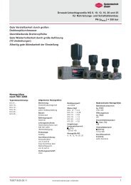
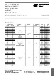
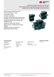
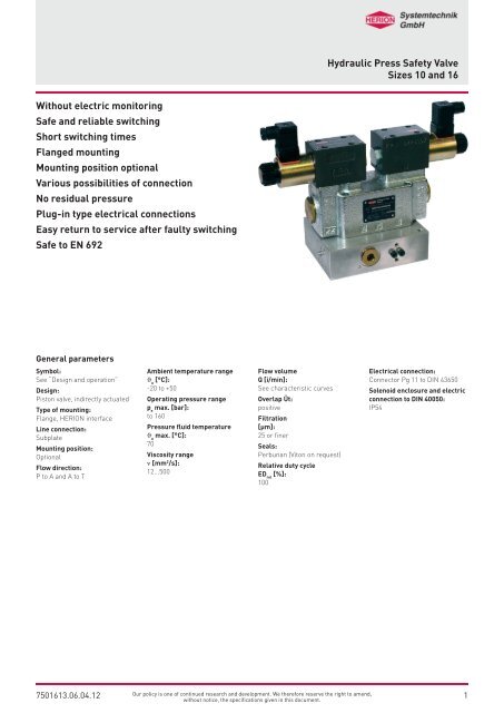
Hydraulic Press Safety Valve<br />
Sizes 10 and 16<br />
Without electric monitoring<br />
Safe and reliable switching<br />
Short switching times<br />
Flanged mounting<br />
Mounting position optional<br />
Various possibilities of connection<br />
No residual pressure<br />
Plug-in type electrical connections<br />
Easy return to service after faulty switching<br />
Safe to EN 692<br />
General parameters<br />
Symbol:<br />
See “Design and operation”<br />
Design:<br />
Piston valve, indirectly actuated<br />
Type of mounting:<br />
Flange, HERION interface<br />
Line connection:<br />
Subplate<br />
Mounting position:<br />
Optional<br />
Flow direction:<br />
P to A and A to T<br />
Ambient temperature range<br />
J u<br />
[°C]:<br />
-20 to +50<br />
Operating pressure range<br />
p e<br />
max. [bar]:<br />
to 160<br />
Pressure fluid temperature<br />
J u<br />
max. [°C]:<br />
70<br />
Viscosity range<br />
n [mm 2 /s]:<br />
12...500<br />
Flow volume<br />
Q [i/min]:<br />
See characteristic curves<br />
Overlap Üt:<br />
positive<br />
Filtration<br />
[μm]:<br />
25 or finer<br />
Seals:<br />
Perbunan (Viton on request)<br />
Relative duty cycle<br />
ED rel<br />
[%]:<br />
100<br />
Electrical connection:<br />
Connector Pg 11 to DIN 43650<br />
Solenoid enclosure and electric<br />
connection to DIN 40050:<br />
IP54<br />
7501613.06.04.12<br />
Our policy is one of continued research and development. We therefore reserve the right to amend,<br />
without notice, the specifications given in this document.<br />
1
Hydraulic Press Safety Valve Sizes 10 and 16<br />
Technical Data<br />
Press safety valve<br />
Type<br />
designation<br />
Size Weight Leakage oil<br />
volume<br />
Valve not<br />
actuated<br />
Valve<br />
actuated<br />
Control<br />
volume<br />
Switching<br />
time<br />
(on)<br />
Switching<br />
time<br />
(off)<br />
Number of<br />
switching<br />
per hour<br />
Rated voltage U n<br />
Standard voltages<br />
(Special voltages<br />
on request)<br />
Current<br />
draw P 20<br />
DN [kg] Q L<br />
[cm 3 /min] Q L<br />
[cm 3 /min] V St<br />
[cm 3 /min] te [ms] ta [ms] z [1/h] [V] [V] [Hz] [W] [VA] [W] [VA]<br />
BPM 10V... 10 9.5 200 500 3.5 64 17 15000 24 32.7 32.7 5205394.7236<br />
BPM 10S... 10 9.5 200 500 3.5 35 15 3600 120 60<br />
230 50<br />
Inrush<br />
Holding<br />
Cat. No.<br />
130 50 5203036.7224<br />
BPM 16V... 16 26 250 600 6 67 14 15000 24 32.7 32.7 5205395.7236<br />
BPM 16S... 16 26 250 600 6 35 20 3600 120 60<br />
230 50<br />
130 50 5203037.7224<br />
Subplate<br />
Type<br />
designation<br />
Size<br />
Interface<br />
Line<br />
connection<br />
Number<br />
of line connections<br />
Interface<br />
for pressure switch<br />
Interface<br />
for 2- way valve<br />
Weight<br />
m<br />
Cat. No.<br />
DN P A T [kg]<br />
PPM 10 A4002100<br />
PPM 16A5003100<br />
BPM 10V...<br />
BPM 10S...<br />
BPM 16V...<br />
BPM 16S...<br />
10<br />
10<br />
16<br />
16<br />
HERION<br />
HERION<br />
HERION<br />
HERION<br />
R1/2<br />
R1/2<br />
R3/4<br />
R3/4<br />
2<br />
1<br />
2<br />
-<br />
2<br />
1<br />
2<br />
-<br />
2<br />
1<br />
2<br />
-<br />
yes<br />
no<br />
yes<br />
-<br />
yes<br />
no<br />
yes<br />
-<br />
2.8<br />
2.8<br />
6<br />
-<br />
1451003<br />
2840082<br />
1451110<br />
-<br />
Type code<br />
Press safety valve<br />
B PM 10 V 21 10 A 76 001 2 O O<br />
1 2 3 4 5 6 7 8 9 10 11 12<br />
1 Equipment group: B – Control block<br />
2 Operating characteristics: PM – Press safety valve for<br />
mechanical<br />
3 DN: 10<br />
16<br />
4 Actuation: S – AC solenoid, pressuresealed,<br />
without manual<br />
override<br />
V – DC solenoid, pressuresealed,<br />
without manual<br />
override<br />
5 Control mode: 21 – Pilot S 6<br />
internal control oil inlet<br />
internal control oil outlet<br />
6 Electrical connection: 10 – Plug-in type connector on<br />
solenoid to DIN 43650<br />
7 Line connection: A – Subplate, HERION interface<br />
8 Operating pressure: 76 – 160 bar<br />
9 Code No.: 007 – DN 16<br />
011 – DN 10<br />
Hydraulically monitored<br />
10 Engineering version: 1 – (with DN 16)<br />
2 – (with DN 10)<br />
11 Additional data: O – Standard design<br />
12 Sealing material: O – Perbunan<br />
V – Viton<br />
Subplate<br />
P PM 10 A 4 001 1 O O<br />
1 2 3 4 5 6 7 8 9<br />
1 Equipment group: P – Subplate<br />
2 Operating characteristics: PM – Press safety valve for<br />
mechanical presses<br />
3 DN: 10<br />
16<br />
4 Connection pattern: A – HERION dimensions<br />
5 Line connection: 4 – G 1/2” (DN 10)<br />
5 – G 3/4” (DN 16)<br />
6 Code No.: 002 – No connections on rear<br />
side, no connections for<br />
pressure switch and 2/2<br />
directional valve. Connections<br />
for PSV DN 10 only<br />
003 – Standard design for PSV<br />
DN 10 and DN 16<br />
7 Engineering version: 1<br />
8 Additional data: O – Standard design<br />
9 Sealing material: O – Perbunan<br />
V – Viton<br />
2<br />
Our policy is one of continued research and development. We therefore reserve the right to amend,<br />
without notice, the specifications given in this document.<br />
7501613.06.04.12
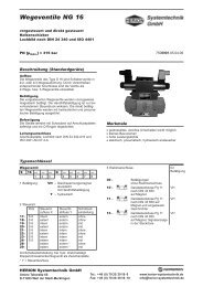
Hydraulic Press Safety Valve Sizes 10 and 16<br />
Design<br />
Device consisting of two pilot operated 4/2 directional control valves.<br />
Application<br />
Press safety valve for control of hydraulically actuated clutch/brake<br />
combinations and brakes.<br />
Design and operation<br />
Rest position<br />
1 3 4 2<br />
Switching position<br />
1 3 4 2<br />
7<br />
5<br />
6<br />
8<br />
7<br />
5<br />
6<br />
8<br />
The press safety valve (PSV) mainly serves for control of hydraulically<br />
actuated clutch/brake combinations. For reasons of safety it must be<br />
ensured that in case of failure of one component<br />
a) the press cannot start inadvertantly<br />
b) the disengagement and braking of the press is effected safety.<br />
Safety rule require that each switching be monitored for accurate<br />
function. Up to now the cyclic monitoring has been carried out by<br />
electric switches. This new valve, however monitors itself hydraulically:<br />
In case of a faultive switching the valve is automatically locked. This<br />
guarantees a safe disengagement of the combination or prevents a<br />
possible engagement.<br />
In rest position the solenoids 1 and 2 of the pilot valves 3 and 4 are<br />
de-energized. Pistons 5 and 6 are held in center position by the<br />
combined action of hydraulic press and the forces of springs 7 and 8.<br />
Pressure port P is closed. Working port A is connected with tank port<br />
T.<br />
In switching position, solenoids 1 and 2 of pilot valves 3 and 4 are<br />
energized. Pistons 5 and 6 are relieved on the spring side. As the pump<br />
pressure is building up, they are pressed outwards contrary to the<br />
force of spring 7 and 8.<br />
Pump port P is now connected with working port A. Connections A-T<br />
and P-T are blocked.<br />
7501613.06.04.12<br />
Our policy is one of continued research and development. We therefore reserve the right to amend,<br />
3<br />
without notice, the specifications given in this document.
Hydraulic Press Safety Valve Sizes 10 and 16<br />
Design and operation<br />
Faulty switching position<br />
Subplate<br />
1 3 4 2<br />
7<br />
5<br />
6<br />
8<br />
Faultive switching may be caused e.g. by failure of power supply, breaking<br />
of a spring or slicking of a piston.<br />
In the faulty switching shown, solenoid 1 is energized, solenoid 2 deenergizd.<br />
Piston 6 is pressurized by hydraulic oild on the spring side.<br />
This causes both pistons to move beyond the center position to the left<br />
end positions.<br />
Pump port P is closed. Working port A is connected with tank port T.<br />
This means that there is no residual pressure between P and A.<br />
In order to shift the vale back to its rest position, the pump port P must<br />
be connected with the tank port T.<br />
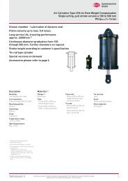
The subplate serves as a base onto which the press safety valve is<br />
flanged. This subplate can be equipped with the following units:<br />
1. Pressure switch<br />
In order to make trouble shooting easier, a pressure switch can be<br />
used. it is flanged onto the subplate without any additional piping.<br />
2. 2/2-directional control valve<br />
This valve can be used for electric pressure relief of the system.<br />
It can also be flanged onto the subplate without any additional<br />
piping.<br />
4<br />
Our policy is one of continued research and development. We therefore reserve the right to amend,<br />
without notice, the specifications given in this document.<br />
7501613.06.04.12
Hydraulic Press Safety Valve Sizes 10 and 16<br />
Dimensional drawing BPM 10<br />
Nut<br />
tightening torque<br />
max 6 Nm<br />
M5 x 30 DIN 912 - 10.9<br />
tightening torque = 7.6 Nm<br />
M6 x 45 DIN 912 - 10.9<br />
tightening torque = 13 Nm<br />
M8, 20 deep<br />
Subplate<br />
M10, 20 deep<br />
7501613.06.04.12<br />
Our policy is one of continued research and development. We therefore reserve the right to amend,<br />
5<br />
without notice, the specifications given in this document.
Hydraulic Press Safety Valve Sizes 10 and 16<br />
Dimensional drawing BPM 16<br />
Nut<br />
tightening torque<br />
max 6 Nm<br />
M5 x 30 DIN 912 - 10.9<br />
tightening torque = 7.6 Nm<br />
M8 x 45 DIN 912 - 10.9<br />
tightening torque = 13 Nm<br />
M12, 20 deep<br />
Subplate<br />
6<br />
Our policy is one of continued research and development. We therefore reserve the right to amend,<br />
without notice, the specifications given in this document.<br />
7501613.06.04.12
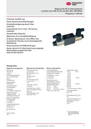
Hydraulic Press Safety Valve Sizes 10 and 16<br />
Connection diagram (example)<br />
1 Clutch/brake assembly<br />
2 Housing<br />
3 Oil supply<br />
4 Damping component<br />
5 Pressure switch<br />
6 PSV<br />
7 2/2-directional control valve<br />
8 Hydraulic power pack<br />
7501613.06.04.12<br />
Our policy is one of continued research and development. We therefore reserve the right to amend,<br />
7<br />
without notice, the specifications given in this document.
Hydraulic Press Safety Valve Sizes 10 and 16<br />
Characteristic curves DN 10 Characteristic curves DN 16<br />
P > A<br />
A > T<br />
with<br />
faulty<br />
switching<br />
A > T<br />
with<br />
normal<br />
switching<br />
A > T<br />
with<br />
faulty<br />
switching<br />
A > T<br />
with<br />
normal<br />
switching<br />
Spare parts PSV 10<br />
Press safety valve B PM 10 V 10 A...<br />
Spare parts PSV 16<br />
Press safety valve B PM 16 V 10 A...<br />
Part Qty. Designation Cat. No.<br />
1 2 Pilot valve assly with solenoid VAC<br />
Pilot valve assly with solenoid VDC<br />
52052497224<br />
52053937236<br />
2 8 O-ring 0701252<br />
3 3 O-ring 0701256<br />
4 2 O-ring 0701264<br />
5 2 Spring 0723440<br />
6 2 Solenoid AC<br />
Solenoid DC<br />
7224<br />
7236<br />
7 2 Connector 0657859<br />
8 4 Mounting bolts 0700413<br />
Part Qty. Designation Cat. No.<br />
1 2 Pilot valve assly with solenoid VAC<br />
Pilot valve assly with solenoid VDC<br />
52052497224<br />
52053937236<br />
2 8 O-ring 0701252<br />
3 3 O-ring 0701292<br />
4 2 O-ring 0701266<br />
5 2 Spring 0723320<br />
6 2 Solenoid AC<br />
Solenoid DC<br />
7224<br />
7236<br />
7 2 Connector 0657859<br />
8 4 Mounting bolts 0700443<br />
8<br />
Our policy is one of continued research and development. We therefore reserve the right to amend,<br />
without notice, the specifications given in this document.<br />
7501613.06.04.12
Hydraulic Press Safety Valve Sizes 10 and 16<br />
Safety instructions<br />
• In situations involving DC voltage-actuated solenoids, avoid using<br />
free-wheeling diodes as far as possible to attenuate the interrupting<br />
voltage (disconnection times will be prolonged).<br />
• The electrical data of the valves and the press control system must<br />
be in concordance.<br />
• The overall control system of the press must comply with DIN 692.<br />
• The valve solenoids must be connected to the control circuit by<br />
separate lines.<br />
• The valve solenoids must be connected to the control circuit by<br />
separate lines.<br />
• Only suitably trained and experienced personnel may install our<br />
product and put it into operation.<br />
• Operation is exclusively permissible within the characteristic<br />
technical data.<br />
• Carry out function test after installation has been completed.<br />
• Horizontal mounting position.<br />
• If, in conjunction with the press safety valve, an orifice is used for<br />
damping the clutch, it must be ensured that any penetration into the<br />
(P) port of the valve is prevented (e.g. by positive fit).<br />
• For safety reasons no other components must be mounted between<br />
the valve and clutch or brake.<br />
• Special maintenance is unnecessary.<br />
• Repairs must only be carried out by the valve manufacturer or by<br />
qualified personnel trained by the valve manufacturer.<br />
• Important for use at presses:<br />
The combination with the electrical press control must meet the<br />
DIN EN ISO 13849-1 requirements.<br />
All liability is denied for unauthorized modification of the units,<br />
installation or usage not in accordance with the manual, the local<br />
safety regulations and the principles of DIN EN ISO 13849-1.<br />
7501613.06.04.12<br />
Our policy is one of continued research and development. We therefore reserve the right to amend,<br />
9<br />
without notice, the specifications given in this document.
Hydraulic Press Safety Valve Sizes 10 and 16<br />
HERION <strong>Systemtechnik</strong> <strong>GmbH</strong><br />
Untere Talstraße 65<br />
71263 Weil der Stadt<br />
Tel.: +49 (0) 7033/3018-0<br />
Fax: +49 (0) 7033/3018-10<br />
info@herion-systemtechnik.de<br />
www.herion-systemtechnik.de<br />
A subsidiary of the Norgren and IMI group of companies<br />
Distribution and Service<br />
• in 75 countries through the Norgren service network<br />
HERION <strong>Systemtechnik</strong><br />
Sales Partners<br />
China<br />
ESTUN INDUSTRIAL AUTOMATION CO., LTS<br />
155,Jiangjun Road, Jiangning Economical & Technical<br />
Development Zone, Nanjing, 211100 P.R.C.<br />
Tel.: +86-25-52785915<br />
E-Mail: info@estun.com<br />
www.estun.com<br />
Japan<br />
Riken Optech Corporation<br />
2-6-9, Higashi Ohi, Shinagawa-ku,<br />
Tokyo 140-8533<br />
Tel.: +81 3 34748602<br />
E-Mail: contact@rikenoptech.com<br />
www.rikenoptech.com<br />
Korea<br />
CHUNGWOO CO., LTD.<br />
# 416-4 Dokjeongri<br />
Janganmyun Hwaseongsi<br />
Kyungkido, Korea<br />
Tel.: +82 (0)31 351-5340<br />
E-Mail: blueox2@unitel.co.kr<br />
www.chungwooco.co.kr<br />
Spain<br />
EUROTECH SYSTEMS, S.L.<br />
Av. Can LLuch, 25<br />
08690 SANTA COLOMA DE CERVELLO<br />
Tel: +34 93 634 0101<br />
E-Mail: eurotech@eurotechsys.com<br />
www.eurotechsys.com<br />
South Africa<br />
Ernest Lowe ELCO<br />
Pneumatic & Hydraulic Automation Solutions<br />
6, Skew Road, Boksburg North 1459,<br />
Gauteng, South Africa<br />
Tel.: +27 (11) 898-6600<br />
E-Mail: corporate@elco.co.za<br />
www.elco.co.za<br />
Taiwan<br />
Full Life Trading Co., Ltd.<br />
16F-4, No.2, Jian Ba Rd. Chung Ho City<br />
Taipei County, Taiwan 23562<br />
Tel.: +886-2-82261860<br />
E-Mail: sales-dept@fulllifetrading.com<br />
www.fulllifetrading.com<br />
Turkey<br />
Power Pnomatik Proses A. Ş<br />
Necatibey Cad. No:44/2<br />
Karaköy<br />
Ýstanbul 34420<br />
Tel.: +90 212 2938870<br />
E-Mail: info@powerpnomatik.com<br />
www.powerpnomatik.com<br />
10<br />
Our policy is one of continued research and development. We therefore reserve the right to amend,<br />
without notice, the specifications given in this document.<br />
7501613.06.04.12