Download - Herion Systemtechnik GmbH
Download - Herion Systemtechnik GmbH
Download - Herion Systemtechnik GmbH

Create successful ePaper yourself
Turn your PDF publications into a flip-book with our unique Google optimized e-Paper software.
Hydraulic Overload Protection Unit DN 16-63<br />
Overload protection for mechanical presses prevents machine<br />
components and tools from damage and excessive load<br />
Directly acting overload protection<br />
Fast reponse times < 10 ms<br />
Low pressure peaks<br />
Excellent repeatability<br />
Infinitely variable adjustment of press force,<br />
set either by manual or electronic control<br />
Suitable for double crank presses with<br />
unbalanced load<br />
Suitable for automated machines<br />
Quick and easy resetting after overload<br />
tripping<br />
Suitable as measuring device for<br />
determination of press force<br />
Technical data<br />
Operating fluid:<br />
Hydraulic oil<br />
Cut-off pressure<br />
P A max [bar]:<br />
420<br />
Hydraulic fluid temp.<br />
ϑ m max. [ o C]:<br />
70<br />
Ambient temp. range<br />
ϑ m max. [ o C]:<br />
-20 to +50<br />
Viscosity range<br />
ν [mm 2 ]:<br />
12 to 500<br />
Mounting position:<br />
any<br />
Seal material:<br />
Perbunan, Viton on request<br />
Ordering example<br />
see page 6<br />
7501897.06.02.11 Our policy is one of continued research and development. We therefore reserve the right to amend,<br />
without notice, the specifications given in this document.<br />
1
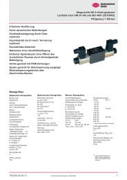
Hydraulic Overload Protection Unit DN 16-63<br />
Design<br />
Pilot operated hydraulic pressure control valve, cartridge type.<br />
For single crank presses<br />
For double crank presses<br />
Mode of operation (general)<br />
An oil-filled cylinder which serves as a cushion is situated in the flux<br />
path between connecting rod and slide. The cylinder is preloaded<br />
with hydraulic pressure p v .<br />
At each operating stroke the hydraulic pressure increases but<br />
remains below the set cut-off pressure p A .<br />
The delay in response depends on the operating conditions and<br />
on the quality of the overload protection system.<br />
The requirement to achieve the fastest possible response is<br />
fulfilled by the system described in this brochure.<br />
In an overload situation the cut-off pressure is reached causing the<br />
valve to open. The hydraulic pressure breaks down immediately and<br />
releases the slide from the mechanical load.<br />
Cut-off pressure<br />
Preload pressure<br />
Oil cushion<br />
Connection for<br />
overload block<br />
2 Our policy is one of continued research and development. We therefore reserve the right to amend,<br />
7501897.06.02.11<br />
without notice, the specifications given in this document.
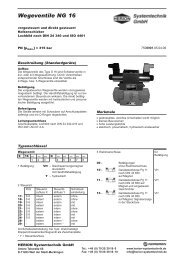
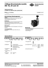
Hydraulic Overload Protection Unit DN 16-63<br />
Function<br />
• For single crank presses (as illustrated)<br />
• For multiple crank presses with balanced load on<br />
connecting rods<br />
• Setting of the cut-off pressure either manually<br />
(as illustrated) or electrically from a remote source<br />
• For double crank presses with unbalanced load on connecting rods<br />
• Adjustment of cut-off pressure either manually or electrically from a<br />
remote source (as illustrated)<br />
The preload pressure in the oil cushion cylinder is produced by<br />
means of a pneumatically driven hydraulic pump. The actual value of<br />
the pressure is a function of the setting of the air-pressure regulating<br />
valve and the translation ratio of the pump.<br />
The difference between preload and cut-off pressures is governed by<br />
the piston area ratio in the pilot valve of the overload block. In the<br />
pilot valve the increase in pressure corresponding to an overload<br />
situation acts against the preload pressure and, at a level determined<br />
by the piston area ratio, causes the pilot valve to open.<br />
This in turn releases pressure at the control side of the main valve<br />
which then also opens so that the cushion cylinder pressure falls to<br />
zero.<br />
The actual level of the cut-off pressure can be set as required by<br />
adjusting the air pressure at the pressure control valve. As the<br />
preload pressure acts on the check valve, it is necessary to release<br />
the pressure prior to adjusting the cut-off pressure to a lower valve.<br />
This is accomplished either electrically or manually by means of a<br />
2-way valve.<br />
The pressure switch which indicates that the system is ready for<br />
operation is set at 50 bar. In an overload situation the electrical<br />
contact is used to switch off the press and to shut off the air<br />
pressure by means of a 3/2 directional valve.<br />
The pressure relief valve in the hydraulic circuit is set to correspond<br />
to the maximum press force and serves to protect the machine in the<br />
event of an incorrect adjustment of the overload protection system.<br />
For this arrangement, the cut-off pressure is set by means of a<br />
proportional pressure control valve. This valve is closed when<br />
switched off so that the 3/2 directional valve is not required.<br />
In an unbalanced overload situation, non-return valves fitted into the<br />
valve block prevent interaction between the pressure cushion<br />
cylinders, thus avoiding canting of the press slide.<br />
The various circuits illustrated can be combined to meet applications<br />
as required.<br />
Power packs are standardly available with 12.5, 25, 40 and 63 liter<br />
tanks.<br />
Further arrangements are available on request.<br />
7501897.06.02.11 Our policy is one of continued research and development. We therefore reserve the right to amend,<br />
without notice, the specifications given in this document.<br />
3
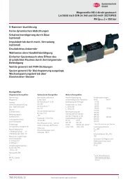
Hydraulic Overload Protection Unit DN 16-63<br />
Installation<br />
Flanged type<br />
• For single crank presses<br />
Inline type<br />
• For double or multiple crank presses<br />
For double crank press applications the overload prevention unit has<br />
to be fitted inline.<br />
In order to achieve faster response, the piping should be arranged to<br />
offer minimum resistance to the fluid flow.<br />
For single crank presses where it is not possible to flange the valve<br />
(e.g. lack of space), it may be necessary to install the inline type.<br />
In this case the port which is no<br />
longer used is sealed by a plate. As this requirement occurs only<br />
occasionally in practice, it is not considered further in this brochure.<br />
The overload valve block is bolted directly onto the connection of<br />
the cylinder volume.<br />
This installation offers minimum resistance to the fluid flow as additional<br />
pipe connections between oil cushion and valve are not<br />
required.<br />
The arrangement is particularly effective with respect to achieving<br />
fast response during overload. Fitting of the block is quickly and<br />
easily carried out.<br />
4 Our policy is one of continued research and development. We therefore reserve the right to amend,<br />
7501897.06.02.11<br />
without notice, the specifications given in this document.
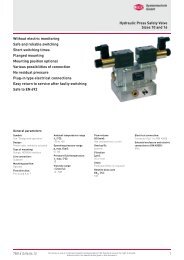
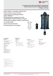
Hydraulic Overload Protection Unit DN 16-63<br />
Selection and calculation<br />
1 = Overload valve block<br />
2 = Air/hydraulic pump<br />
3 = Air pressure regulating valve<br />
4 = Compressed air supply<br />
Cut-off pressure<br />
The press is protected against overload at the cut-off pressure p A .<br />
The value of the cut-off pressure may be obtained theoretically using<br />
the following calculation, but in any event may not exceed the<br />
allowable max. pressure of 420 bar.<br />
P A = 10 4 · F [bar]<br />
F [kN] = Nominal press force<br />
Nominal size<br />
A<br />
A [mm 2 ] = Total pressure area of pressure cushion(s)<br />
In the final calculation the deformation of the pressure cushion must<br />
be allowed for.<br />
The calculation size DN is obtained from the following formula.<br />
The next larger size from the sales program will then be the correct<br />
one for the application in question.<br />
DN =<br />
Preset values<br />
Setting of the overload protection unit depends upon chosen values<br />
for:<br />
- Cut-off pressure<br />
- Area ratio of the valve piston<br />
- Translation ratio of the pump<br />
- Air pressure<br />
If, for example, a cut-off pressure of 390 bar is required, then using<br />
a standard first stage valve piston of area ratio 1:1.3 and a standard<br />
pump translation ratio of 1:60, the compressed air pressure is<br />
calculated as follows:<br />
P I = 390 = 5 [bar]<br />
1.3 · 60<br />
This results in a hydraulic preload pressure of<br />
P V = 390 or 5 · 60 = 300 bar<br />
1.3<br />
When establishing system parameters it is necessary to observe<br />
that the compressed air pressure does not fall below the minimum<br />
adjustble value of 1.5 bar, and also that the maximum allowable<br />
supply pressure is not exceeded.<br />
n [min -1 ] = Speed of crankshaft<br />
H [mm] = Crank diameter (stroke)<br />
A [mm 2 ] = Total pressure area of pressure cushion(s)<br />
cos α [-] = H - 2h<br />
H<br />
h [mm] = Overload travel. This is the distance<br />
from the lowest point of slide movement<br />
to the point where the overload<br />
protection system must react in the<br />
least favourable case. This distance is<br />
determined by the machine manufacturer.<br />
sin β [-] = sin α · H<br />
Types<br />
After the nominal bore size has been established, the type of the<br />
overload protection unit is selected. The selection depends on the<br />
press type as well as the connecting rod loading characteristics.<br />
2 · L Pl<br />
L PI [mm] = Length of connecting rod<br />
7501897.06.02.11 Our policy is one of continued research and development. We therefore reserve the right to amend,<br />
without notice, the specifications given in this document.<br />
5
Hydraulic Overload Protection Unit DN 16-63<br />
Type codes, type survey, technical information<br />
Type codes for overload block<br />
D AV S 25 F 99 011 3 O O<br />
1 2 3 4 5 6 7 8 9 10<br />
1 Equipment group: D – Pressure valve<br />
2 Operating characteristics:AV – Pressure cut-off with selected<br />
piston area ratio<br />
3 Design: S – Poppet valve,<br />
pilot controlled<br />
4 Nominal size: 16<br />
25<br />
40<br />
63<br />
5 Connection: A – Flanged<br />
F – Inline<br />
K – remote control<br />
pilot operated<br />
6 Pressure stage: 99 – > 315 bar<br />
7 Code No.: 010 – Without non-return valves<br />
011 – With non-return valves<br />
8 Engineering version: 3 – DIN-Cartridge<br />
9 Cut-off ratio: A – Standard type<br />
O – Special design<br />
10 Seal material: O – Perbunan<br />
V – Viton<br />
Type survey<br />
Overload valve block<br />
Flanges, SAE 6000 to be welded *)<br />
DN Type Typ code Weight Order Port Port Port<br />
No. A B T<br />
16 Flanged DAVS16A990103AO 1:1,15 6.7 kg 6015856 – – G1/2<br />
16 Flanged DAVS16A990103AO 1:1,3 6.7 kg 6015853 – – G1/2<br />
16 Flanged DAVS16A990103AO 1:1,6 6.7 kg 6015855 – – G1/2<br />
16 Flanged DAVS16A990103AO 1:1,9 6.7 kg 6015854 – – G1/2<br />
16 Inline DAVS16F990103AO 1:1,15 7.2 kg 6015887 G1/2 G1/2 G1/2<br />
16 Inline DAVS16F990103AO 1:1,3 7.2 kg 6015884 G1/2 G1/2 G1/2<br />
16 Inline DAVS16F990103AO 1:1,6 7.2 kg 6015886 G1/2 G1/2 G1/2<br />
16 Inline DAVS16F990103AO 1:1,9 7.2 kg 6015885 G1/2 G1/2 G1/2<br />
25 Flanged DAVS25A990103AO 1:1,15 8.9 kg 6015925 – – G1<br />
25 Flanged DAVS25A990103AO 1:1,3 8.9 kg 6015922 – – G1<br />
25 Flanged DAVS25A990103AO 1:1,6 8.9 kg 6015924 – – G1<br />
25 Flanged DAVS25A990103AO 1:1,9 8.9 kg 6015923 – – G1<br />
25 Inline DAVS25F990103AO 1:1,15 15.1 kg 6015844 G1 G1 G1<br />
25 Inline DAVS25F990103AO 1:1,3 15.1 kg 6015841 G1 G1 G1<br />
25 Inline DAVS25F990103AO 1:1,6 15.1 kg 6015843 G1 G1 G1<br />
25 Inline DAVS25F990103AO 1:1,9 15.1 kg 6015842 G1 G1 G1<br />
25 Inline, DAVS25F990113AO 1:1,15 15.1 kg 6015907 G3/4 G3/4 G1<br />
with non-return valve<br />
25 Inline, DAVS25F990113AO 1:1,3 15.1 kg 6015903 G3/4 G3/4 G1<br />
with non-return valve<br />
25 Inline, DAVS25F990113AO 1:1,6 15.1 kg 6015906 G3/4 G3/4 G1<br />
with non-return valve<br />
25 Inline, DAVS25F990113AO 1:1,9 15.1 kg 6015905 G3/4 G3/4 G1<br />
with non-return valve<br />
25 Flanged DAVS25KA990102OO 9 kg 8130354 – – G1<br />
remote pilot operated<br />
*) Flanges to be ordered separately.<br />
6 Our policy is one of continued research and development. We therefore reserve the right to amend,<br />
7501897.06.02.11<br />
without notice, the specifications given in this document.
Hydraulic Overload Protection Unit DN 16-63<br />
Geräteübersicht<br />
Overload valve block<br />
Flanges, SAE 6000 to be welded *)<br />
DN Type Typ code Weight Order Port Port Port<br />
No. A B T<br />
40 Flanged DAVS40A990103AO 1:1.15 22.5 kg 6015932 – – G1 1/2<br />
40 Flanged DAVS40A990103AO 1:1.3 22.5 kg 6015929 – – G1 1/2<br />
40 Flanged DAVS40A990103AO 1:1.6 22.5 kg 6015931 – – G1 1/2<br />
40 Flanged DAVS40A990103AO 1:1.9 22.5 kg 6015930 – – G1 1/2<br />
40 Inline DAVS40F990103AO 1:1.15 27.5 kg 6015938 G1 1/2 G1 1/2 G1 1/2<br />
40 Inline DAVS40F990103AO 1:1.3 27.5 kg 6015935 G1 1/2 G1 1/2 G1 1/2<br />
40 Inline DAVS40F990103AO 1:1.6 27.5 kg 6015937 G1 1/2 G1 1/2 G1 1/2<br />
40 Inline DAVS40F990103AO 1:1.9 27.5 kg 6015938 G1 1/2 G1 1/2 G1 1/2<br />
40 Inline, DAVS40F990113AO 1:1.15 27.5 kg 6015832 G1 1/4 G1 1/4 G1 1/2<br />
with non-return valve<br />
40 Inline, DAVS40F990113AO 1:1.3 27.5 kg 6015829 G1 1/4 G1 1/4 G1 1/2<br />
with non-return valve<br />
40 Inline, DAVS40F990113AO 1:1.6 27.5 kg 6015831 G1 1/4 G1 1/4 G1 1/2<br />
with non-return valve<br />
40 Inline, DAVS40F990113AO 1:1.9 27.5 kg 6015830 G1 1/4 G1 1/4 G1 1/2<br />
with non-return valve<br />
40 Flange DAVS40KA990102OO 30.0 kg 6015560 – – G1 1/2<br />
remote pilot operated<br />
63 Flanged DAVS63A990103AO 1:1.3 75 kg 8130875 – – G2 1/2<br />
63 Inline DAVS63F990103AO 1:1.3 70 kg 8130624 – – G2 1/2<br />
63 Flanged DAVS63KA990102OO 69 kg 6103420 – – G2 1/2<br />
remote pilot operated<br />
*) Flanges to be ordered separately.<br />
7501897.06.02.11 Our policy is one of continued research and development. We therefore reserve the right to amend,<br />
without notice, the specifications given in this document.<br />
7
Hydraulic Overload Protection Unit DN 16-63<br />
Spare parts for flanges<br />
O-ring<br />
Cylinder screw<br />
Part<br />
Part name<br />
SAE 6000-G1/2 SAE 6000-G3/4 SAE 6000-G1 SAE 6000-G1 1/4 SAE 6000-G1 1/2 Order No.<br />
NBR 70<br />
1 O-ring (18.64 x 3.53) 1 - - - - 0701338 0701544<br />
1 O-ring (25.0 x 3.53) - 1 - - - 0701342 0701548<br />
1 O-ring (32.93 x 3.53) - - 1 - - 0701347 0701553<br />
1 O-ring (37.7 x 3.53) - - - 1 - 0701350 0701556<br />
1 O-ring (47.23 x 3.53) - - - - 1 0701353 0701559<br />
Order No.<br />
NBR 90<br />
Mounting screws<br />
2 Cylinder screw<br />
(M 8 x 30 DIN 912-10.9)<br />
2 Cylinder screw<br />
(M 10 x 40 DIN 912-10.9)<br />
2 Cylinder screw<br />
(M 12 x 45 DIN 912-10.9)<br />
2 Cylinder screw<br />
(M 14 x 50 DIN 912-10.9)<br />
2 Cylinder screw<br />
(M 16 x 55 DIN 912-10.9)<br />
4 - - - - 0700437<br />
- 4 - - - 0701366<br />
- - 4 - - 0700472<br />
- - - 4 - 0663356<br />
- - - - 4 0700492<br />
Flanges kg Order No.<br />
SAE 6000–G1/2 0.3 0769876<br />
SAE 6000–G3/4 0.6 0764877<br />
SAE 6000–G1 0.9 0764878<br />
Flanges kg Order No.<br />
SAE 6000–G1 1/4 1.4 0764879<br />
SAE 6000–G1 1/2 2.4 0764880<br />
SAE 3000–G2 1/2 1.7 1450274<br />
8 Our policy is one of continued research and development. We therefore reserve the right to amend,<br />
7501897.06.02.11<br />
without notice, the specifications given in this document.
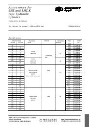
Hydraulic Overload Protection Unit DN 16-63<br />
Dimensions<br />
Flanged type D AV S..A 99 010 2 A O<br />
DN a b c d e f g h i j k l m n o p<br />
16 40 75 32 31 124.5 20 47.5 75 10 110 40 11 123 ø26.5 M 10 15<br />
25 50 95 45 42.5 140.5 22 57.5 90 12.5 115 60 12.5 143 ø34.2 M 12 20<br />
40 60 135 75 62 184.5 32.5 82.5 135 15 165 90 17 183 ø53 M 16 30<br />
63 – 200 90 95 267 115 115 190 20 230 105 45 300 ø78.,6 M 20 27<br />
DN q r s t u A T P M A M V<br />
16 85 33 22 5 48 ø16 G1/2 G3/8 G1/4 G1/4<br />
25 110 43 38 2 70 ø25 G1 G1/2 G1/4 G1/4<br />
40 160 65 50 6 96 ø40 G1 1/2 G1/2 G1/4 G1/4<br />
63 237 45 – 6 – ø63 G2 1/2<br />
Inline type D AV S..F 99 010 2 A O<br />
DN a b c d e f g h i j k l m n o p<br />
16 40 90 67 34 132 30 55 90 10 110 70 10 138 190 9 178<br />
25 50 125 85 44 153 37 70 116 12 140 101 12 173 240 13 223<br />
40 60 150 120 64 197 45 95 150 20 190 120 15 198 310 18 258<br />
63 – 200 90 95 300 150 150 270 15 300 170 15 300 – 18 –<br />
DN q r s t u A B T P M A M V<br />
16 80 40 22 40 48 G1/2 G1/2 G1/2 G3/8 G1/4 G1/4<br />
25 110 55 38 50 70 G1 G1 G1 G1/2 G1/4 G1/4<br />
40 130 65 50 65 96 G1 1/2 G1 1/2 G1 1/2 G1/2 G1/4 G1/4<br />
63 330 215 – 60 – 2 x G2 G2 1/2<br />
7501897.06.02.11 Our policy is one of continued research and development. We therefore reserve the right to amend,<br />
without notice, the specifications given in this document.<br />
9
Hydraulic Overload Protection Unit DN 16-63<br />
Einbaumaße<br />
Inline type with non-return valves D AV S..F 99 011 2 A O<br />
DN a b c d e f g h i j k l m n o p<br />
25 50 130 112 45 77 148 115 116 50 230 101 14 178 320 13 228<br />
40 60 160 143 75 98 210 160 150 85 320 120 20 208 430 18 268<br />
DN q r s t u v w A B T P M A M B M V<br />
25 1109 50 38 133 31,8 45 70 G3/4 G3/4 G1 G1/2 G1/4 G1/4 G1/4<br />
40 140 65 50 172 42 55 96 G1 1/4 G1 1/4 G1 1/2 G1/2 G1/4 G1/4 G1/4<br />
Flanged type, remote pilot operated D AV S..KA 99 010 2 O O<br />
DN a b c d e f g h i j k l m n o p<br />
16<br />
25<br />
40 60 135 75 62 96 32.5 82.5 135 15 165 90 17 183 ø53 M 16 30<br />
63 – 200 25 95 – 115 95 190 20 230 105 50 270 ø78.6 M 20 27<br />
DN q r s t A T P M A M V<br />
16<br />
25<br />
40 160 65 50 6 ø40 G1 1/2 G3/8 G1/4 G1/4<br />
63 197 95 – 0<br />
* The connections for pressure gauges M A , M B und M V are not shown in the installation drawings.<br />
10 Our policy is one of continued research and development. We therefore reserve the right to amend,<br />
7501897.06.02.11<br />
without notice, the specifications given in this document.
Hydraulic Overload Protection Unit DN 16-63<br />
Questionnaire for hydraulic overload protection unit<br />
Supplier<br />
Customer<br />
Address<br />
Untere Talstraße 65<br />
71263 Weil der Stadt<br />
Tel.: +49 (0) 70 33/30 18-0<br />
Fax: +49 (0) 70 33/30 18-10<br />
info@herion-systemtechnik.de<br />
Department<br />
Contact<br />
Telephone<br />
Date<br />
Press type<br />
Press<br />
description<br />
Model<br />
Max. press force F = kN<br />
Max. stroke H = mm<br />
Max. speed n = min -1<br />
Equipment type Press specification data<br />
Travel during overload h = mm<br />
or<br />
Angle before BDC<br />
where system is respond = degree<br />
Length of connecting rod L Pl = mm<br />
Total area of pressure cushion A = mm 2<br />
or<br />
Piston diameter D = mm<br />
Number of connecting rods z = -<br />
Load on connecting rod Balanced<br />
Overload block<br />
Flanged type<br />
Inline type<br />
Inline type<br />
with non-return valves<br />
(unbalanced load)<br />
Unbalanced<br />
Y<br />
Y<br />
Y<br />
Y<br />
Y<br />
Hydraulic power pack<br />
Adjutment of cut-off pressure<br />
Manual<br />
Remotely controlled<br />
Nominal voltage U N = V Hz<br />
Y<br />
Y<br />
Further<br />
information<br />
7501897.06.02.11 Our policy is one of continued research and development. We therefore reserve the right to amend,<br />
without notice, the specifications given in this document.<br />
11
HERION <strong>Systemtechnik</strong> <strong>GmbH</strong><br />
Untere Talstraße 65<br />
71263 Weil der Stadt<br />
Tel.: +49 (0) 7033/3018-0<br />
Fax: +49 (0) 7033/3018-10<br />
info@herion-systemtechnik.de<br />
www.herion-systemtechnik.de<br />
A subsidiary of the Norgren and IMI group<br />
of companies<br />
Distribution and Service<br />
x in 75 countries through the Norgren service network<br />
HERION <strong>Systemtechnik</strong><br />
Sales Partners<br />
China<br />
ESTUN INDUSTRIAL AUTOMATION CO., LTS<br />
155,Jiangjun Road, Jiangning Economical & Technical<br />
Development Zone, Nanjing, 211100 P.R.C.<br />
Tel.: +86-25-52785915<br />
E-Mail: info@estun.com<br />
www.estun.com<br />
Germany<br />
(PLZ-Gebiete 17-28, 30-32)<br />
Kraeft <strong>GmbH</strong> <strong>Systemtechnik</strong><br />
Riedemannstr. 1<br />
27572 Bremerhaven<br />
Tel.: +49 (0)471/95208-0<br />
E-Mail: info@kraeft-systemtechnik.de<br />
www.kraeft-systemtechnik.de<br />
Japan<br />
Riken Optech Corporation<br />
2-6-9, Higashi Ohi, Shinagawa-ku,<br />
Tokyo 140-8533<br />
Tel.: +81 3 34748602<br />
E-Mail: contact@rikenoptech.com<br />
www.rikenoptech.com<br />
Korea<br />
CHUNGWOO CO., LTD.<br />
# 416-4 Dokjeongri<br />
Janganmyun Hwaseongsi<br />
Kyungkido, Korea<br />
Tel.: +82 (0)31 351-5340<br />
E-Mail: blueox2@unitel.co.kr<br />
www.chungwooco.co.kr<br />
Spain<br />
EUROTECH SYSTEMS, S.L.<br />
Av. Can LLuch, 25<br />
08690 SANTA COLOMA DE CERVELLO<br />
Tel: +34 93 634 0101<br />
E-Mail: eurotech@eurotechsys.com<br />
www.eurotechsys.com<br />
South Africa<br />
Ernest Lowe ELCO<br />
Pneumatic & Hydraulic Automation Solutions<br />
6, Skew Road, Boksburg North 1459,<br />
Gauteng, South Africa<br />
Tel.: +27 (11) 898-6600<br />
E-Mail: corporate@elco.co.za<br />
www.elco.co.za<br />
Taiwan<br />
Full Life Trading Co., Ltd.<br />
16F-4, No.2, Jian Ba Rd. Chung Ho City<br />
Taipei County, Taiwan 23562<br />
Tel.: +886-2-82261860<br />
E-Mail: sales-dept@fulllifetrading.com<br />
www.fulllifetrading.com<br />
Turkey<br />
Power Pnomatik Proses A.Ş<br />
Necatibey Cad. No:44/2<br />
Karaköy<br />
Ýstanbul 34420<br />
Tel.: +90 212 2938870<br />
E-Mail: info@powerpnomatik.com<br />
www.powerpnomatik.com<br />
12<br />
HERION <strong>Systemtechnik</strong> <strong>GmbH</strong>, Untere Talstraße 65, 71263 Weil der Stadt,<br />
Telefon +49 (0) 70 33/30 18-0, Fax +49 (0) 70 33/30 18-10<br />
7501897.06.02.11<br />
info@herion-systemtechnik.de, www.herion-systemtechnik.de