Masterlog_uk - Europe
Masterlog_uk - Europe
Masterlog_uk - Europe

You also want an ePaper? Increase the reach of your titles
YUMPU automatically turns print PDFs into web optimized ePapers that Google loves.
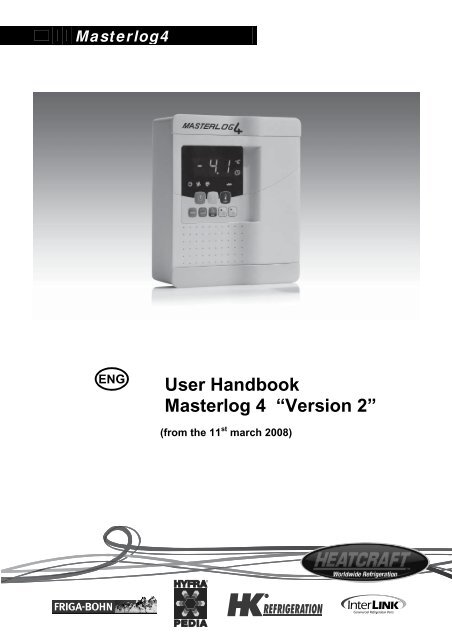
<strong>Masterlog</strong>4<br />
User Handbook<br />
<strong>Masterlog</strong> 4 “Version 2”<br />
(from the 11 st march 2008)
OPERATING INSTRUCTIONS<br />
MASTERLOG 4 “Version 2”<br />
The default parameter settings for the MASTERLOG 4 (bn1) are selected for operation with chilling evaporators<br />
equipped with an air defrost system. For a different operating mode one of the following programs may be<br />
selected:<br />
‘bn1’= chilling with air defrost<br />
‘bn2’= chilling with electrical defrost<br />
‘bn3’= refrigeration with electrical defrost<br />
‘bn4’= ambient chilling with air defrost<br />
‘bn5’=‘bn2’ with 2 evaporators<br />
‘bn6’=‘bn3’ with 2 evaporators<br />
”DO NOT USE ‘bn0’”<br />
Proceed as follows to select one of these programs:<br />
1. Switch off the <strong>Masterlog</strong>4.<br />
2. Switch the <strong>Masterlog</strong>4 back on again while simultaneously pressing the “prg” button until the value ‘bn0’<br />
appears.<br />
3. Select the program required using the “up” and “down” keys<br />
4. Press “set” to confirm the selection.<br />
”Set” Key ”prg” Key “Up/Down” Keys<br />
ATTENTION:<br />
‣ The defrost parameters [‘dI’: interval between 2 defrosts, ‘dT’: temperature at end of defrost (electrical) and ‘dP’:<br />
maximum defrost duration] are factory-set values. Depending on use of the cold storage room, these parameters<br />
must be modified to ensure correct defrosting of the evaporator.<br />
‣ To carry out a manual defrost cycle, press the “defrost” key<br />
for more than 5 sec.<br />
‣ The MASTERLOG 4 relays are “potential-free” contacts. To supply these contacts, it is essential to connect<br />
terminals 1, 4, 7 and 10 as well as aux. terminals 13 and 16 if necessary (refer to the electrical wiring diagram<br />
enclosed with the products).<br />
‣ The MASTERLOG 4 possesses three configurable inputs (terminals 22/23, 24/25 et 26/27). Input n°1<br />
(terminals 22 and 23) may be set as an external alarm coming from the unit (parameter A4=1, except<br />
application 2 evaporators). Some units are equipped with a standard ‘fault contact’ (refer to wiring diagram).<br />
We recommend you connect this alarm contact to the MASTERLOG 4.<br />
‣ If the keypad is locked, modify the parameter H2 (H2=1).<br />
IMPORTANT: Standard and modified parameters are saved in case of an electrical power failure. When<br />
downloading a program, these values are reset in compliance with the basic parameter setting chart.<br />
Code +050004036 Rel. 1.0 – 11/03/2008 3
1 - Wiring<br />
Sensors: 18 - 19 Ambient probe (PROBE 1)<br />
20 - 21 End of defrost probe (PROBE 2)<br />
Digital inputs:<br />
Auxiliary:<br />
Wiring RS485:<br />
22 - 23 Digital input 1 (DI 1) - Parameters A4<br />
24 - 25 Digital input 2 (DI 2) - Parameters A5<br />
26 - 27 Digital input 3 (DI 3) - Parameters A9<br />
13 - 14 AUX 1 – Parameters H1<br />
16 - 17 AUX 2 – Parameters H5<br />
28 GND<br />
29 TX/RX+<br />
30 TX/RX-<br />
Relay characteristics: Refer to chapter 8. Technical characteristics<br />
R1 =30A<br />
R2=16A<br />
R3=8A<br />
R4=8A<br />
R5=16A<br />
Code +050004036 Rel. 1.0 – 11/03/2008 4
2 - Display<br />
Symbols<br />
Colour<br />
Meaning with the symbol<br />
illuminated<br />
Meaning with the symbol<br />
blinking<br />
Amber<br />
Compressor operational<br />
Compressor in standby and ready<br />
to start<br />
Amber<br />
Condenser fan operational<br />
Condenser fan in standby and<br />
ready to start<br />
Amber<br />
Defrost in progress<br />
Condenser fan in standby and<br />
ready to start<br />
AUX Amber Auxiliary output set as AUX output<br />
Heating element blocking function<br />
enabled at start up<br />
(Option)<br />
Yellow<br />
At least 1 defrost is programmed in<br />
real time<br />
Red<br />
Red<br />
Amber<br />
Amber<br />
External alarm delayed<br />
Auxiliary output set as heater<br />
Activation of a continuous cycle<br />
Alarm present or alarm on digital<br />
input immediate or delayed<br />
Malfunction (e.g. probe<br />
disconnected)<br />
Heating element blocking function<br />
enabled at start up<br />
Continuous cycle cannot be<br />
enabled<br />
(Option)<br />
Red HACCP function enabled New HACCP alarm memorised<br />
Code +050004036 Rel. 1.0 – 11/03/2008 5
3 - Parameters:<br />
3-1 . Access to parameters:<br />
Modify the set point only<br />
Press and hold SET for 1 second<br />
Use the up and down keys to modify the set<br />
point<br />
Press SET to confirm the<br />
value<br />
Access to all parameters<br />
Press and hold PRG and<br />
SET at the same time for<br />
5 seconds<br />
"00" is displayed<br />
Use the up and down keys to select<br />
“22”<br />
Press SET<br />
Save parameters Do not save parameters Cancel an alarm Manual defrost<br />
Press and hold PRG for 5<br />
seconds<br />
Do not press any other<br />
keys for 60 seconds until<br />
the display returns to the<br />
temperature value<br />
Press PRG<br />
Press and hold DEF<br />
for 5 seconds<br />
Code +050004036 Rel. 1.0 – 11/03/2008 6
3-2 . Rotation of the parameters list menu<br />
5s<br />
(OPTION)<br />
Time range<br />
Probe<br />
HACCP<br />
(OPTION)<br />
Control<br />
Configuration<br />
Compressor<br />
Fan<br />
Defrost<br />
Alarm<br />
‘Set’= to access or quit a parameter<br />
‘Set’= to access a block<br />
‘Prg’= to quit a block<br />
Code +050004036 Rel. 1.0 – 11/03/2008 7
4- List of parameters:<br />
The parameters may vary depending on the model of MD33<br />
/: Probe parameters<br />
Display<br />
Parameter and description<br />
Measurement<br />
unit<br />
Min<br />
Max<br />
Bn<br />
1<br />
Bn<br />
2<br />
Bn<br />
3<br />
Bn<br />
4<br />
Bn<br />
5<br />
Bn<br />
6<br />
/2<br />
/3<br />
/4<br />
/5<br />
/6<br />
/tI<br />
tE<br />
/P<br />
/A2<br />
Probe measurement delay<br />
1=immediate response<br />
15=delayed response<br />
Probe display speed<br />
0=slow<br />
15=fast<br />
Virtual probe (between probe 1 and probe 2)<br />
0=Setting of probe 1<br />
50=average between probe 1 and probe 2<br />
100=Setting of probe 2<br />
Selection °C or °F<br />
0=°C<br />
1=°F<br />
Display decimal point<br />
0=Yes<br />
1=No<br />
Selection of probe to be displayed on controller<br />
1=virtual probe<br />
2=probe 1<br />
3=probe 2<br />
4=probe 3<br />
5=probe 4<br />
6=probe 5<br />
7=set point<br />
Selection of probe to be displayed on a remote<br />
display<br />
0=no remote display present<br />
1=virtual probe<br />
2=probe 1<br />
3=probe 2<br />
4=probe 3<br />
5=probe 4<br />
6=probe 5<br />
Selection of probe type<br />
0=standard NTC (black probe)<br />
1=high-temperature NTC (beige probe)<br />
2=PTC<br />
Configuration of probe 2<br />
0=probe 2 absent or not used<br />
1=product probe (used for display)<br />
2=defrost probe<br />
3=condensation probe<br />
4=anti-frost probe<br />
- 1 15 4 4 4 4 4 4<br />
- 0 15 0 0 0 0 0 0<br />
- 0 100 0 0 0 0 0 0<br />
Select 0 1 0 0 0 0 0 0<br />
Select 0 1 0 0 0 0 0 0<br />
- 1 7 2 2 2 2 2 2<br />
- 0 6 0 0 0 0 0 0<br />
- 0 2 0 0 0 0 0 0<br />
- 0 4 0 2 2 0 2 2<br />
/A3 Configuration of probe 3 / digital input 1<br />
Same as probe 2<br />
Configuration of probe 4 / digital input 2<br />
/A4 Same as probe 2<br />
Configuration of probe 5 / digital input 3<br />
/A5 Same as probe 2<br />
- 0 4 0 0 0 0 2 2<br />
- 0 4 0 0 0 0 0 0<br />
- 0 4 0 0 0 0 0 0<br />
/c1 Calibration of probe 1 °C/°F -20 20 0 0 0 0 0 0<br />
/c2 Calibration of probe 2 °C/°F -20 20 0 0 0 0 0 0<br />
/c3 Calibration of probe 3 °C/°F -20 20 0 0 0 0 0 0<br />
/c4 Calibration of probe 4 °C/°F -20 20 0 0 0 0 0 0<br />
/c5 Calibration of probe 5 °C/°F -20 20 0 0 0 0 0 0<br />
Code +050004036 Rel. 1.0 – 11/03/2008 8
d: Defrost parameters<br />
Display<br />
Parameter and description<br />
Measurement<br />
unit<br />
Min<br />
Max<br />
Bn<br />
1<br />
Bn<br />
2<br />
Bn<br />
3<br />
Bn<br />
4<br />
Bn<br />
5<br />
Bn<br />
6<br />
d0<br />
Type of defrost<br />
0=defrost with elec. element ends with<br />
temperature or time<br />
1=defrost with hot gas ends with temperature or<br />
time<br />
2=defrost with elec. element ends with time<br />
3=defrost with hot gas ends with time<br />
4= defrost with elec. element ends with time or<br />
temperature (if defrost ends with time ED1 and ED2<br />
are not displayed)<br />
Select 0 4 2 0 0 2 0 0<br />
dI Interval between 2 defrosts Time 0 250 8 8 6 12 8 6<br />
dt1 Temperature at end of evaporator defrost °C/°F -50 200 4 4 4 4 4 4<br />
dt2 Temperature at end of aux. evaporator defrost °C/°F -50 200 4 4 4 4 4 4<br />
dP1 Maximum evaporator defrost duration Min 1 250 45 45 30 45 45 30<br />
dP2 Maximum aux. evaporator defrost duration Min 1 250 45 45 30 45 45 30<br />
d3 Delayed defrost activation Min 0 250 0 0 0 0 0 0<br />
d4<br />
Defrost when the controller is switched on<br />
0=no<br />
1=yes<br />
Select 0 1 0 0 0 0 0 0<br />
d5 Delay defrost when the controller is switched on Min 0 250 120 240 240 120 240 240<br />
Block display during defrost<br />
0=alternating display of temperature and DEF<br />
d6 1=display temperature present before defrost<br />
- 0 2 2 2 2 2 2 2<br />
2=always display DEF<br />
dd Dripping duration after defrost Min 0 15 0 4 4 0 4 4<br />
High-temperature alarm (AH) exclusion duration<br />
d8 after defrost and/or door open<br />
Time 0 15 1 1 1 1 1 1<br />
d8d Alarm timer after door opening (alarm “dor”) Min 0 250 2 2 2 2 2 2<br />
Priority defrost for delayed compressor<br />
start/stop<br />
d9 0=respected<br />
Select 0 1 0 0 0 0 0 0<br />
1=not respected (priority defrost)<br />
d/1 Read defrost probe 1 °C/°F - - - - - - - -<br />
d/2 Read defrost probe 2 °C/°F - - - - - - - -<br />
dC<br />
Defrost duration time base<br />
0=hours/minutes<br />
1=Minutes/seconds<br />
Select 0 1 0 0 0 0 0 0<br />
d10<br />
Smart defrost: Compressor running time with an<br />
evaporator temperature below D11 to start<br />
defrost<br />
0=function disabled<br />
dC 0 250 0 0 0 0 0 0<br />
>0 =running time<br />
d11 Temperature threshold for smart defrost °C/°F -20 20 1 1 1 1 1 1<br />
d12<br />
Auto-adaptive advanced defrost<br />
0=skip defrost disconnected, automatic variation<br />
disconnected<br />
1=skip defrost disconnected, automatic variation<br />
connected<br />
2= skip defrost connected, automatic variation<br />
- 0 3 0 0 0 0 0 0<br />
disconnected<br />
3= skip defrost connected, automatic variation<br />
connected<br />
Average defrost duration in percentage in<br />
dn relation to dt1 or dt2<br />
- 1 100 65 65 65 65 65 65<br />
dH Proportional variation factor of dI - 0 100 50 50 50 50 50 50<br />
Code +050004036 Rel. 1.0 – 11/03/2008 10
A: Alarm parameters<br />
Display<br />
Parameter and description<br />
Measurement<br />
unit<br />
Min<br />
Max<br />
Bn<br />
1<br />
Bn<br />
2<br />
Bn<br />
3<br />
Bn<br />
4<br />
Bn<br />
5<br />
Bn<br />
6<br />
A0 Alarms and fans differential °C/°F 0.1 20 0.2 0.2 0.2 0.2 0.2 0.2<br />
A1<br />
Type of alarm threshold: low-temperature (AL)<br />
and high-temperature (AH)<br />
0=AL and AH threshold in relation to set point<br />
(factory set)<br />
Select 0 1 0 0 0 0 0 0<br />
1=AL and AH absolute values<br />
Low-temperature alarm threshold (AL) <br />
AL differential > 0°C if factory set<br />
°C/°F -50 200 5 5 5 6 5 5<br />
High-temperature alarm threshold (AH) <br />
AH differential > 0°C if factory set<br />
°C/°F -50 200 5 5 5 6 5 5<br />
Ad Temperature alarm delay (AL and AH) Min 0 250 45 45 45 45 45 45<br />
Configuration of digital input 1 terminals 22<br />
& 23<br />
0=input not used.<br />
1=Instantaneous external alarm (IA)<br />
2=Delayed external alarm (dA)<br />
3=Defrost authorisation (except IR33M)<br />
4=Start defrost with external contact<br />
5=Door contact: Stop compressor and fans<br />
6=Controller remote stoppage<br />
A4 7=Night screen contact (day/night contact)<br />
- 0 14 0 0 0 0 0 0<br />
8=Low pressure switch input for pump-down<br />
9=Stop fans with door contact<br />
10=Direct/reverse operation (hot/cold)<br />
11=Light detector<br />
12=Activation of auxiliary output<br />
13= Door contact without light control: Stop<br />
compressor and fans<br />
14= Door contact without light control: Stop fans.<br />
A5<br />
Configuration of digital input 2 terminals 24<br />
& 25<br />
Same as digital input 1<br />
- 0 14 0 0 0 0 0 0<br />
Authorisation to stop the compressor with<br />
external alarm<br />
A6 0=compressor always off<br />
Min 0 100 0 0 0 0 0 0<br />
100=compressor always on<br />
A7 Alarm timer with contact Min 0 250 0 0 0 0 0 0<br />
Authorisation of alarms Ed1and Ed2 (defrost<br />
end with time)<br />
A8 0=no<br />
Select 0 1 0 1 1 0 1 1<br />
1=yes<br />
A9<br />
Configuration of digital input 3 terminals 26<br />
& 27<br />
Same as digital input 1<br />
- 0 14 0 0 0 0 0 0<br />
Ado<br />
Light control with door contact<br />
0=off<br />
1=on<br />
Select 0 1 0 0 0 0 0 0<br />
Condenser high-temperature alarm threshold<br />
Ac (CHT)<br />
°C/°F 0.0 200 70 70 70 70 70 70<br />
Condenser high-temperature alarm differential<br />
AE (CHT)<br />
°C/°F 0.1 20 10 10 10 10 10 10<br />
Acd Condenser high-temperature alarm delay (CHT) Min 0 250 0 0 0 0 0 0<br />
AF<br />
Light output switch-off timer with light detector<br />
0=door detector<br />
>0=room detector<br />
Sec 0 250 0 0 0 0 0 0<br />
ALF Anti-frost alarm threshold (AFr) °C/°F -50 200 -5 -5 -5 -5 -5 -5<br />
AdF Anti-frost alarm delay (AFr) Min 0 15 1 1 1 1 1 1<br />
Code +050004036 Rel. 1.0 – 11/03/2008 11
F: Ventilation parameters<br />
Display<br />
Parameter and description<br />
Measurement<br />
unit<br />
Min<br />
Max<br />
Bn<br />
1<br />
Bn<br />
2<br />
Bn<br />
3<br />
Bn<br />
4<br />
Bn<br />
5<br />
Bn<br />
6<br />
F0<br />
Fans control<br />
0=fan always on except in phases F2, F3, Fd<br />
1=fan thermostat controlled according to<br />
difference between controller temperature and<br />
evaporator temperature (in relation to F1)<br />
2=fan thermostat controlled according to<br />
evaporator temperature (in relation to F1)<br />
Select 0 2 0 0 0 0 0 0<br />
F1 Fan start up temperature °C/°F -50 200 5 5 5 5 5 5<br />
F2<br />
F3<br />
Fan control according to compressor<br />
0=fan on when the compressor is off<br />
1=fan off when the compressor is off<br />
Fan operation during defrost<br />
0=fan on during defrost<br />
1=fan off during defrost<br />
Select 0 1 0 0 0 0 0 0<br />
Select 0 1 0 1 1 0 1 1<br />
Fd Fans stoppage time after dripping Min 0 15 0 2 2 0 2 2<br />
F4 Condenser fan switch off temperature °C/°F -50 200 40 40 40 40 40 40<br />
F5 Condenser fans differential °C/°F 0.1 20 5 5 5 5 5 5<br />
h: Configuration parameters<br />
Display<br />
Parameter and description<br />
Measurement<br />
unit<br />
Min<br />
Max<br />
Bn<br />
1<br />
Bn<br />
2<br />
Bn<br />
3<br />
Bn<br />
4<br />
Bn<br />
5<br />
Bn<br />
6<br />
H0 Serial address - 0 207 1 1 1 1 1 1<br />
H1<br />
H2<br />
H3<br />
Operating mode of relay 4<br />
0=relay open in case of alarm<br />
1=relay closed in case of alarm<br />
2=auxiliary output: Open or close relay 4 by<br />
pressing the AUX key<br />
3=light output<br />
4=auxiliary evaporator defrost output<br />
5=pump-down valve output<br />
6=condenser fan output<br />
7=output for compressor star/delta start up<br />
8=auxiliary output if the controller is off<br />
9=light output is open if the controller is off<br />
10=no function associated with this output<br />
11=controller reverse (hot) output with dead<br />
zone<br />
12=2 nd compressor output<br />
13=2 nd compressor output with rotation<br />
Keypad and/or remote control authorisation<br />
0=Prohibit SET (modification of parameters type<br />
F) and modification of the set point<br />
1 =authorise all<br />
2= Prohibit SET (modification of parameters type<br />
F), modification of the set point and modification via<br />
remote control<br />
3=Prohibit modification via remote control<br />
4=Prohibit UP/AUX, SET (modification of<br />
parameters type F) and DOWN/DEF (defrost)<br />
5= Prohibit UP/AUX, SET (modification of<br />
parameters type F), DOWN/DEF (defrost) and<br />
modification of set point.<br />
6= Prohibit UP/AUX, SET (modification of<br />
parameters type F), DOWN/DEF (defrost) and<br />
modification of set point.<br />
Remote control parameter access code<br />
0=access to parameters without code<br />
Select 0 13 1 1 1 1 4<br />
Select 0 6 1 1 1 1 1 1<br />
- 0 255 0 0 0 0 0 0<br />
4<br />
Code +050004036 Rel. 1.0 – 11/03/2008 12
Display<br />
Parameter and description<br />
Measurement<br />
unit<br />
Min<br />
Max<br />
Bn<br />
1<br />
Bn<br />
2<br />
Bn<br />
3<br />
Bn<br />
4<br />
Bn<br />
5<br />
Bn<br />
6<br />
H4<br />
H5<br />
H6<br />
H8<br />
Buzzer operation<br />
0=in case of an alarm<br />
1=always off<br />
Operating mode of relay 5<br />
0=relay open in case of alarm<br />
1=relay closed in case of alarm<br />
2=auxiliary output: Open or close relay 4 by<br />
pressing the AUX key<br />
3=light output<br />
4=auxiliary evaporator defrost output<br />
5=pump-down valve output<br />
6=condenser fan output<br />
7=output for compressor star/delta start up<br />
8=auxiliary output if the controller is off<br />
9=light output is open if the controller is off<br />
10=no function associated with this output<br />
11=controller reverse (hot) output with dead<br />
zone<br />
12=2nd compressor output<br />
13=2nd compressor output with rotation<br />
Blocking of keys:<br />
0=all keys enabled<br />
1=set disabled<br />
2=down key disabled<br />
3=set and down key disabled<br />
4=up key disabled<br />
5=up key and set disabled<br />
6=up and down keys disabled<br />
7=up, down and set keys disabled<br />
8=prg disabled<br />
9=prg and set disabled<br />
10=prg and down key disabled<br />
11=prog, down key and set disabled<br />
12=prg and up key disabled<br />
13=prg, up key and set disabled<br />
14=prg, up and down keys disabled<br />
15=all keys disabled<br />
Selection of the light or auxiliary output for<br />
activation of the time range<br />
0=time range linked to the light<br />
1=time range linked to the auxiliary output<br />
Select 0 1 0 0 0 0 0 0<br />
Select 0 13 10 10 10 11 10 10<br />
- 0 255 0 0 0 0 0 0<br />
Select 0 1 0 0 0 0 0 0<br />
H9<br />
Validation of set point variation with the time<br />
range<br />
0=not enabled (tof set point +r4)<br />
1=enabled (ton set point normal)<br />
Select<br />
0<br />
1 0 0 0 0 0 0<br />
Hdh Heating element blocking at start up<br />
differential<br />
°C/°F -50 200 0 0 0 0 0 0<br />
Code +050004036 Rel. 1.0 – 11/03/2008 13
HA: HACCP alarm parameters (OPTIONAL)<br />
Display<br />
Parameter and description<br />
Measurement<br />
unit<br />
Min<br />
Max<br />
HAn Number of HA alarm events recorded - 0 15<br />
HA Time/date of last HA recorded - -<br />
y__ Year Year 0 99<br />
M__ Month Month 1 12<br />
d__ Day Day 1 7<br />
h__ Hour Hour 0 23<br />
n__ Minute Min 0 59<br />
t__ Duration Duration 0 99<br />
HA1 Time/date of last HA recorded - - -<br />
y__ Year Year 0 99<br />
M__ Month Month 1 12<br />
d__ Day Day 1 7<br />
h__ Hour Hour 0 23<br />
n__ Minute Min 0 59<br />
t__ Duration Duration 0 99<br />
HA2 Time/date of last HA recorded - - -<br />
y__ Year Year 0 99<br />
M__ Month Month 1 12<br />
d__ Day Day 1 7<br />
h__ Hour Hour 0 23<br />
n__ Minute Min 0 59<br />
t__ Duration Duration 0 99<br />
HFn<br />
Number of HF alarm events recorded<br />
- 0 15<br />
HF Time/date of last HF recorded<br />
- - -<br />
y__ Year Year 0 99<br />
M__ Month Month 1 12<br />
d__ Day Day 1 7<br />
h__ Hour Hour 0 23<br />
n__ Minute Min 0 59<br />
t__ Duration Duration 0 99<br />
Code +050004036 Rel. 1.0 – 11/03/2008 14
Display<br />
Parameter and description<br />
Measurement<br />
unit<br />
HF1 Time/date of last HF recorded<br />
- - -<br />
y__ Year Year 0 99<br />
M__ Month Month 1 12<br />
d__ Day Day 1 7<br />
h__ Hour Hour 0 23<br />
n__ Minute Min 0 59<br />
t__ Duration Duration 0 99<br />
Min<br />
Max<br />
HF2 Time/date of last HF recorded - 0 -<br />
y__ Year Year 0 99<br />
M__ Month Month 1 12<br />
d__ Day Day 1 7<br />
h__ Hour Hour 0 23<br />
n__ Minute Min 0 59<br />
t__ Duration Duration 0 99<br />
Htd<br />
HACCP alarm delay<br />
Htd=0 function disabled<br />
Min 0 250<br />
td: Defrost time parameters (OPTIONAL)<br />
Display<br />
Parameter and description<br />
Measurement<br />
unit<br />
Min<br />
Max<br />
td1<br />
d__<br />
Defrost 1 time range<br />
Day<br />
0=disabled<br />
1=Monday<br />
2=Tuesday<br />
3=Wednesday<br />
4=Thursday<br />
5=Friday<br />
6=Saturday<br />
7=Sunday<br />
8=Monday to Friday<br />
9=Monday to Saturday<br />
10=Saturday and Sunday<br />
11=Every day<br />
- - -<br />
Day 0 11<br />
h__ Hour Hour 0 23<br />
n__ Minute Min 0 59<br />
td2 Defrost 2 time range<br />
- - -<br />
d__ Day Day 0 11<br />
h__ Hour Hour 0 23<br />
n__ Minute Min 0 59<br />
Code +050004036 Rel. 1.0 – 11/03/2008 15
Display<br />
Parameter and description<br />
Measurement<br />
unit<br />
td3 Defrost 3 time range<br />
- - -<br />
d__ Day Day 0 11<br />
h__ Hour Hour 0 23<br />
n__ Minute Min 0 59<br />
td4 Defrost 4 time range<br />
- - -<br />
d__ Day Day 0 11<br />
h__ Hour Hour 0 23<br />
n__ Minute Min 0 59<br />
td5 Defrost 5 time range<br />
- - -<br />
d__ Day Day 0 11<br />
h__ Hour Hour 0 23<br />
n__ Minute Min 0 59<br />
td6 Defrost 6 time range<br />
- - -<br />
d__ Day Day 0 11<br />
h__ Hour Hour 0 23<br />
n__ Minute Min 0 59<br />
td7 Defrost 7 time range<br />
- - -<br />
d__ Day Day 0 11<br />
h__ Hour Hour 0 23<br />
n__ Minute Min 0 59<br />
td8 Defrost 8 time range<br />
- - -<br />
d__ Day Day 0 11<br />
h__ Hour Hour 0 23<br />
n__ Minute Min 0 59<br />
Min<br />
Max<br />
ton<br />
d__<br />
h__<br />
n__<br />
Light illumination/auxiliary time range<br />
Day<br />
0=disabled<br />
1=Monday<br />
2=Tuesday<br />
3=Wednesday<br />
4=Thursday<br />
5=Friday<br />
6=Saturday<br />
7=Sunday<br />
8=Monday to Friday<br />
9=Monday to Saturday<br />
10=Saturday and Sunday<br />
11=Every day<br />
Hour<br />
Minute<br />
- - -<br />
Day 0 11<br />
Hour 0 23<br />
Min 0 59<br />
Code +050004036 Rel. 1.0 – 11/03/2008 16
Display<br />
Parameter and description<br />
Measurement<br />
unit<br />
Min<br />
Max<br />
tof<br />
d__<br />
h__<br />
n__<br />
Light/auxiliary off time range<br />
Day (same as ton)<br />
Hour<br />
Minute<br />
- - -<br />
Day 0 11<br />
Hour 0 23<br />
Min 0 59<br />
tc<br />
y__<br />
M__ Month<br />
d__<br />
Time/date programming<br />
Year<br />
Day<br />
- - -<br />
Year 0 99<br />
Month 1 12<br />
Day 1 31<br />
u__<br />
n__<br />
t__<br />
Day of the week<br />
1=Monday<br />
2=Tuesday<br />
3=Wednesday<br />
4=Thursday<br />
5=Friday<br />
6=Saturday<br />
7=Sunday<br />
Hour<br />
Minute<br />
Day 1 7<br />
Hour 0 23<br />
Min 0 59<br />
Code +050004036 Rel. 1.0 – 11/03/2008 17
5 – List of alarm codes<br />
Code Description Display icon Alarm relay Buzzer Reset<br />
rE<br />
E0<br />
E1<br />
E2<br />
E3<br />
E4<br />
Before any intervention, always check the wiring.<br />
Controller virtual probe damaged or disconnected<br />
Ambient probe S1 damaged or disconnected<br />
Defrost probe S2 damaged or disconnected<br />
Probe S3 damaged or disconnected<br />
Probe S4 damaged or disconnected<br />
Flashing<br />
Flashing<br />
Flashing<br />
Flashing<br />
Flashing<br />
On On Automatic<br />
Off Off Automatic<br />
Off Off Automatic<br />
Off Off Automatic<br />
Off Off Automatic<br />
Probe S5 damaged or disconnected<br />
Flashing<br />
Off Off Automatic<br />
‘---‘ Probe not validated None Off Off Automatic<br />
LO<br />
HI<br />
AFr<br />
IA<br />
dA<br />
dEF<br />
Low temperature alarm<br />
High temperature alarm<br />
Anti-frost alarm<br />
Instantaneous alarm with external contact<br />
Delayed alarm with external contact<br />
Defrost in progress<br />
Flashing<br />
Flashing<br />
Flashing<br />
Flashing<br />
Flashing<br />
On<br />
On On Automatic<br />
On On Automatic<br />
On On Manual<br />
On On Automatic<br />
On On Automatic<br />
Off Off Automatic<br />
Ed1 Defrost on evaporator 1 finished with time None Off Off Automatic/manual<br />
Ed2 Defrost on evaporator 2 finished with time None Off Off Automatic/manual<br />
Pd<br />
LP<br />
AtS<br />
Maximum pump-down time alarm<br />
Low-pressure alarm<br />
Flashing<br />
Flashing<br />
On On Automatic/manual<br />
On On Automatic/manual<br />
Pump-down automatic start up<br />
Flashing<br />
On On Automatic/manual<br />
cht Condenser high temperature pre-warning None Off Off Automatic/manual<br />
CHT<br />
dor<br />
Etc<br />
EE<br />
EF<br />
Condenser high temperature alarm<br />
Door open too long alarm<br />
Internal clock defective<br />
Machine parameters Eprom error<br />
Operating parameters Eprom error<br />
Flashing<br />
Flashing<br />
Flashing<br />
Flashing<br />
Flashing<br />
On<br />
On<br />
Manual<br />
On On Automatic<br />
Off Off Automatic<br />
Off Off Automatic<br />
Off Off Automatic<br />
HA HACCP alarm type HA Flashing Off Off Automatic<br />
HF HACCP alarm type HF Flashing Off Off Automatic<br />
rCt Controller validated for remote programming None Off Off Automatic<br />
Add Automatic address attribution procedure in progress None Off Off Automatic<br />
Prt Report print-out in progress None Off Off Automatic<br />
ccb Start continuous cycle request Indication<br />
ccE End continuous cycle request Indication<br />
dFb Start defrost request Indication<br />
dFE Stop defrost request Indication<br />
On On Indication<br />
Off Off Indication<br />
rES<br />
Reset manual-reset alarms; reset HACCP<br />
alarms; reset temperature monitoring<br />
Indication<br />
n1 - n6<br />
Indicates an alarm on units 1-6 present in the system<br />
Flashing<br />
dnL Download in progress Indication<br />
d1 - d6 Download errors on units 1-6<br />
Flashing<br />
On On Automatic<br />
Off<br />
Off<br />
Code +050004036 Rel. 1.0 – 11/03/2008 18
6 – Spare parts:<br />
*Controller <strong>Masterlog</strong> 4 with 2 probes (ambient and end of defrost)<br />
code PDEL01957<br />
*Ambient probe<br />
code PDEL00490<br />
*End of defrost probe<br />
code PDEL00455<br />
7 – Miscellaneous:<br />
7 – 1 Test NTC probe for damage:<br />
Temp. °C -35 -30 -25 -20 -15 -10 -5 0 5 10 15 20 25 30<br />
Value KΩ 144 111 86 68 53 42 34 27 22 18 15 12 10 8<br />
7 – 2 Set lighting parameters:<br />
Use AUX 2 (relay 5)<br />
Parameter: H5=3<br />
Bulb connected between terminals 17 & 2<br />
Note: the key must be pressed and held for 2s to switch the lighting on or off.<br />
7 – 3 Connection of the defrost element:<br />
Connect “Element” contactor coil between terminals 8 and 2<br />
7 – 4 Connection of heating element for wine cellars:<br />
Connect “Element” contactor coil between terminals 17 and 2<br />
7 – 5 Operation with 2 <strong>Masterlog</strong>4 1 master and 1 slave:<br />
Master<br />
Slave<br />
PF contact “NO” connection to Digital input available:<br />
of element contactor if terminals 22 &23 A4=4<br />
if terminals 24 &25 A5=4<br />
if terminals 26 &27 A9=4<br />
Interval between 2 defrosts:<br />
Parameter ‘’dI’’=6 hours<br />
Interval between 2 defrosts:<br />
Parameter ‘’dI’’=8 hours<br />
Note: When using an external defrost timer, the configuration is identical to above except that the master is replaced<br />
by a timer.<br />
Code +050004036 Rel. 1.0 – 11/03/2008 19
Code +050004036 Rel. 1.0 – 11/03/2008 20
8. TECHNICAL CHARACTERISTICS<br />
Power Supply: Model E= Voltage: 230 V~, 50/60 Hz; Power: 11.3 VA, 50 mA~ max.<br />
Model A= Voltage: 115 V~, 50/60 Hz; Power: 11.3 VA, 100 mA~ max.<br />
Model H= Voltage: 115...230 V~, 50/60 Hz; Power: 12 VA, 110 mA~ max.<br />
Insulation: guaranteed by the p. supply:<br />
Model E,A,H= Insulation from very low voltage parts: reinforced; 6 mm in air, 8 mm on surface; 3750 V insulation.<br />
Insulation from relay outputs: primary; 3 mm in air, 4 mm on surface; 1250 V insulation.<br />
Input: S1: NTC or PTC, depending on the model<br />
S2: NTC or PTC, depending on the model<br />
D11, S3: voltage-free contact, contact resistance < 10 Ω, closing current 6 mA NTC or PTC, depending on the model<br />
D12, S4: voltage-free contact, contact resistance < 10 , closing current 6 mA NTC or PTC,<br />
depending on the model<br />
D13, S5: voltage-free contact, contact resistance < 10 , closing current 6 mA NTC or PTC, depending on the model.<br />
Maximum distance from probes and digital inputs less than 10 m.<br />
Note: in the installation, keep the power supply and load connections separate from the probe, digital inputs, repeater display and<br />
supervisor cables.<br />
Probe type: NTC std. CAREL= 10 kΩ at 25 °C, range from –50T90 °C; measurement error: 1 °C in the range from –50T50 °C;<br />
3°C in the range from +50T90 °C<br />
NTC high temperature= 50 kΩ at 25 °C, range from –40 T150 °C; measurement error 1.5 °C in the range from –20T115 °C; 4 °C<br />
in the range outside of –40T150 °C<br />
PTC std. CAREL (specifi c model)= 985 Ω at 25 °C, range from –50T150 °C; measurement error: 2 °C in the range –50T50 °C;<br />
4°C in the range +50T150 °C<br />
Relay outputs: according to the model<br />
EN60730-1 (250 V~)<br />
UL 873 (250 V~)<br />
8A 8 (4) A on N.O.; 6 (4) A on N.C.; 2 (2) A on N.C. and N.O. (100000<br />
cycles)<br />
8 A resistive 2 FLA 12 LRA C 300 (30000<br />
cycles)<br />
16 A 10 (4) A up to 60 °C on N.O.; 12 (2) A on N.O. and N.C. (100000<br />
cycles)<br />
12 A resistive 5 FLA 30 LRA C 300 (30000<br />
cycles)<br />
2 Hp 10 (10) A (100000 cycles) 12 A resistive, 12FLA, 72 LRA (30000 cycles)<br />
30 A 12 (10) A (100000 cycles) 12 A resistive, 2HP, 12 FLA (30000 cycles)<br />
• insulation from the very low voltage parts: reinforced; 6 mm in air, 8 on surface; 3750 V insulation<br />
• insulation between the independent relay outputs: basic; 3 mm in air, 4 on surface; 1250 V insulation<br />
Connections:<br />
Type of connection= fixed screw, plug-in for screw blocks or spade with crimped contact; Cross-section=<br />
for cables from 0.5 a 2.5 mm 2<br />
Type of connection= wire cross-section for probes and digital inputs; Cross-section= from 0.5 to 2.5 mm 2<br />
(from 20 to 13 AWG)<br />
Type of connection= wire cross-section for power supply and loads; Cross-section= from 1.5 to 2.5 mm 2<br />
(from 15 to 13 AWG)<br />
Notes: The correct sizing of the power and connection cables between the instrument and the loads is the<br />
responsibility of the installer. In the max load and max operating temp. conditions, the cables used must be<br />
suitable for operation up to 105 °C.<br />
Case:<br />
plastic: dimensions 200 x 240 x 93 mm; bare board and front panel: base dimensions 178 x 86 x 40 mm: front<br />
dimensions 100 x 90 x 12 mm<br />
Assembly:<br />
Display:<br />
Keypad:<br />
wall mounting (with plastic case): using fastening screws (spacing 162.5 x 218.5); panel (with plastic front<br />
panel): using fastening screws (spacing 159.5 x 197.5); panel (bare board): using fastening screws for base<br />
board and using fastening screws for front board.<br />
The controller must be protected against accidental contact to prevent electric shock.<br />
digits: 3 digit LED; display: from -99 to 999; operating status: indicated with LEDs and graphic icons made in the<br />
polycarbonate label applied to the plastic case.<br />
8 mechanical buttons, keypad made in the polycarbonate label applied to the plastic case.<br />
Infrared receiver: available according to the model.<br />
Clock with backup battery: available according to the model.<br />
Buzzer: available on all models.<br />
Clock: error at 25 °C: ± 10 ppm (±5.3 min/year); error in the temperature range –10T60°C: - 50 ppm (-27 min/year);<br />
ageing: < ±5 ppm (±2.7min/year);<br />
Code +050004036 Rel. 1.0 – 11/03/2008 21
Discharge time: typically 6 months (8 months maximum); recharge time: typically 5 hours (
HEATCRAFT<br />
42 Rue Roger SALENGRO<br />
69741 GENAS (LYON) France<br />
Agency