GTI-GT2I_en - Europe
GTI-GT2I_en - Europe
GTI-GT2I_en - Europe

You also want an ePaper? Increase the reach of your titles
YUMPU automatically turns print PDFs into web optimized ePapers that Google loves.
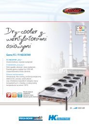
Dual-discharge<br />
unit cooler<br />
Direct expansion industrial range <strong>GTI</strong>/<strong>GT2I</strong><br />
Glycol water industrial range <strong>GTI</strong>-W/<strong>GT2I</strong>-W<br />
Heatcraft reserves itself the right to make changes at any time without preliminary notice - Photos non-contractual<br />
• The 88 models of the <strong>GTI</strong> and <strong>GT2I</strong> range<br />
meet the workplace comfort requirem<strong>en</strong>ts for<br />
laboratories, meat cutting rooms, air locks, etc...<br />
• Exceptionally low noise levels<br />
with the 8P (<strong>GTI</strong>) and 12P (<strong>GT2I</strong>) models.<br />
• The low air flow speed guarantees comfort as well<br />
as accurate control of both temperature and hygrometry<br />
for the 8P and 12P models.<br />
• The 2-speed electric fans guarantee appropriate<br />
noise levels and v<strong>en</strong>tilation (<strong>GT2I</strong>).<br />
Reduced sound<br />
Natural fluids:<br />
Glycol water<br />
<strong>GT2I</strong> / <strong>GT2I</strong>-W<br />
<strong>GTI</strong> / <strong>GTI</strong>-W<br />
12.5 123.5 kW
Food<br />
Food Service<br />
FSM<br />
Food<br />
<strong>GTI</strong> (-W) / <strong>GT2I</strong> (-W)<br />
SuperMarket<br />
- Dual-discharge industrial unit cooler<br />
SUPERMARKET<br />
Market segm<strong>en</strong>ts<br />
Designation<br />
Description<br />
Casing<br />
• The <strong>GTI</strong> (-W) and <strong>GT2I</strong> (-W) casing is made of white pre-painted galvanized steel.<br />
• All models of the <strong>GTI</strong> (-W) and <strong>GT2I</strong> (-W) range are equipped<br />
with intermediate drain pans for the recovery of cond<strong>en</strong>sation.<br />
• On the <strong>GT2I</strong> (-W), each removable (in 1 or 2 sections dep<strong>en</strong>ding on the models),<br />
external drain pan evacuates into a recovery vessel located next to the refrigeration<br />
connections and from where the cond<strong>en</strong>sation is evacuated via a large dim<strong>en</strong>sion<br />
drain pipe (Ø 1 1/2” G).<br />
• <strong>GTI</strong> (-W) and <strong>GT2I</strong> (-W) models are forese<strong>en</strong> with <strong>en</strong>d covers.<br />
• <strong>GTI</strong> (-W) and <strong>GT2I</strong> (-W) are delivered on a wood<strong>en</strong> base.<br />
• <strong>GT2I</strong> (-W) are delivered in their mounting position and designed<br />
for installation flush to the ceiling.<br />
V<strong>en</strong>tilation<br />
• The <strong>GTI</strong> (-W) unit cooler range is equipped with fans Ø 450 mm, 230-400 V/3/50 Hz:<br />
4P = 1,500 rpm, 6P = 1,000 rpm or 8P = 750 rpm<br />
• The <strong>GT2I</strong> (-W) unit cooler range is equipped with fans Ø 630 mm, 400 V/3/50 Hz,<br />
IP 55, class F, with incorporated thermal overload protection, 2 speeds dep<strong>en</strong>ding<br />
on models (factory wired: Δ = high speed):<br />
6/8 P = 1,000/750 rpm or 8/12 P = 750/500 rpm.<br />
• Fan guards are compliant with safety standards.<br />
Coil<br />
• The <strong>GT2I</strong> range is equipped with two new coil configurations optimized<br />
for direct expansion and glycol water applications.<br />
• The highly-effici<strong>en</strong>t and compact standard finned coils of the <strong>GTI</strong> (-W) and <strong>GT2I</strong> (-W)<br />
range are composed of aluminium fins with a spacing of 4.23 or 6.35 mm.<br />
Advantages<br />
Installation<br />
Possibility of supplying a connection kit (option EGK) for the glycol water model<br />
to r<strong>en</strong>der installation easier.<br />
Intermediate drain pans <strong>en</strong>abling installation of optional electric defrost ELU<br />
or EEK kit on the <strong>GT2I</strong> (-W).<br />
Single flow for easier installation.<br />
Servicing / Maint<strong>en</strong>ance<br />
<strong>GT2I</strong> (-W) are equipped with hinged doors and a removable c<strong>en</strong>tral panel <strong>en</strong>abling<br />
east access to electrical and refrigeration connections.<br />
For all work on the <strong>GT2I</strong> (-W), access to the drain pans does not require removal<br />
of the recovery vessel.<br />
58<br />
SUPERMARKET<br />
FSM<br />
Food<br />
SuperMarket<br />
FCS<br />
Food<br />
Cold Storage<br />
FSM Hard Discount - Supermarkets - Hypermarkets<br />
FCS Refrigerated storage and transit stocking - Dispatch c<strong>en</strong>tres – Food processing – Cante<strong>en</strong> kitch<strong>en</strong>s<br />
Certifications<br />
SUPERMARKET<br />
SUPERMARKET<br />
<strong>GTI</strong>(1)-W(2) 34(3)4(4) 4P(5)<br />
<strong>GT2I</strong>(1)-W(2) 36(3) R(4) 6/8P(5)<br />
(1) <strong>GTI</strong> / <strong>GT2I</strong>: Direct expansion unit cooler<br />
(2) W: Glycol water unit cooler<br />
(3) Model<br />
(4) Fin spacing: 4 or R = 4.23 mm - 7 or L = 6,35 mm<br />
(5) 4P = 1,500 rpm - 6P = 1,000 rpm - 8P = 750 rpm<br />
6P/8P = 1,000/750 rpm. - 8P/12P = 750/500 rpm.<br />
Kit<br />
Factory<br />
M60<br />
MM5<br />
MM6<br />
CMU*<br />
CT5<br />
CT6<br />
CM5<br />
CM6<br />
M60<br />
BXT<br />
WCO<br />
EGK<br />
Options<br />
V<strong>en</strong>tilation - <strong>GTI</strong> / <strong>GTI</strong>-W<br />
Fans 230-400V/3/60Hz (adapted fan blades).<br />
Fans 230V/1/50Hz.<br />
Fans 230V/1/60Hz.<br />
V<strong>en</strong>tilation - <strong>GT2I</strong> / <strong>GT2I</strong>-W<br />
CMU* Motors factory wired.<br />
*CMU = CT5, CT6, CM5 or CM6<br />
Single-speed wiring 400V/3/50Hz<br />
Single-speed wiring 400V/3/60Hz<br />
Single-speed wiring 230V/1/50Hz<br />
Single-speed wiring 230V/1/60Hz<br />
Fans 230-400V/3/60Hz (adapted fan blades).<br />
Coil<br />
Blygold Polual XT coil protection.<br />
Glycol water, coolant (please contact us for details).<br />
Glycol water and coolant ext<strong>en</strong>sion.<br />
Defrost - <strong>GTI</strong> / <strong>GTI</strong>-W<br />
E1K E1U Light electric defrost.<br />
HGB Hot gas defrost (coil only).<br />
Defrost - <strong>GT2I</strong> / <strong>GT2I</strong>-W<br />
E1K E1U Light electric defrost.<br />
ELU Electric defrost (coil + drain pan).<br />
HG1 Defrost with hot gas<br />
(coil: hot gas, drain pan: heating elem<strong>en</strong>ts).<br />
EEK<br />
Drain pan electric defrost.<br />
ECK ECU Additional coil electric defrost.<br />
ECB<br />
EIS<br />
Miscellaneous<br />
Full crate packaging (<strong>GT2I</strong> / <strong>GT2I</strong>-W).<br />
Insulated drain pan.<br />
Other options<br />
Please contact us for details.
40<br />
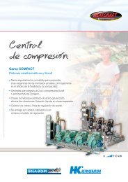
<strong>GTI</strong> (-W) / <strong>GT2I</strong> (-W) - Dual-discharge G 1"<br />
35 industrial unit cooler<br />
1910<br />
850 * 989<br />
85<br />
<strong>GTI</strong> / <strong>GTI</strong>-W<br />
142 1630<br />
142<br />
18 1266<br />
18<br />
<strong>GTI</strong> (-W) 387 - 344 - 347 - 364 - 367<br />
676 40<br />
<strong>GTI</strong> (-W)<br />
387<br />
484 - 487<br />
584 - 587<br />
60<br />
G1”<br />
1914<br />
850<br />
142 2160<br />
142<br />
1218<br />
60<br />
G1”<br />
1071 1089<br />
<strong>GTI</strong> (-W) 484 - 487 - 444 - 464 - 467<br />
2444<br />
18 1126<br />
18<br />
676 40<br />
<strong>GTI</strong> (-W)<br />
344 - 347<br />
364 - 367<br />
444 - 464 - 467<br />
564 - 567<br />
850<br />
1078<br />
21<br />
142 2690<br />
142<br />
21<br />
1071 1619<br />
<strong>GTI</strong> (-W) 584 - 587 - 564 - 567<br />
81<br />
G1”<br />
3016<br />
mm<br />
850<br />
<strong>GT2I</strong> / <strong>GT2I</strong>-W<br />
314 1052<br />
1052 244<br />
18 1504 18<br />
688<br />
<strong>GT2I</strong> (-W) 24 - 26 - 28<br />
167<br />
1500 2662<br />
1500<br />
1445<br />
Ø 1 1/2” G<br />
314 1052<br />
1052 1052<br />
244<br />
18 1504<br />
688<br />
<strong>GT2I</strong> (-W) 34 - 36 - 38<br />
14 x 20<br />
167<br />
1500 3714<br />
1500<br />
314 1052<br />
1052 1052 1052<br />
244<br />
688<br />
<strong>GT2I</strong> (-W) 44 - 46 - 48<br />
167<br />
1500<br />
4766<br />
1500<br />
59
R404A<br />
W<br />
t A1<br />
<strong>GTI</strong> ... + E1U<br />
+15 +2 -1°C<br />
<strong>GTI</strong> (-W) ... 4/6/8P - 1,500/1,000/750 rpm.<br />
Direct expansion <strong>GTI</strong> ... 4/6/8P 344 364 444 464 484 564 584<br />
4P kW 33,7 42,5 45,1 57,6 66,3 68,8 73,1<br />
DT1 = 10 K - SC1 6P kW 27,8 34,5 37,5 46,1 51,7 55,8 60,1<br />
Capacity<br />
8P kW 23,4 28,0 32,1 37,5 40,8 45,6 49,6<br />
R404A (1)<br />
4P kW 18,0 21,5 23,1 30,1 34,7 38,9 41,3<br />
DT1 = 8 K - SC2 6P kW 14,8 17,9 18,9 25,0 28,1 30,9 33,3<br />
8P kW 12,6 14,5 17,0 20,4 22,2 25,2 26,4<br />
4,23 mm<br />
Glycol water <strong>GTI</strong>-W ... 4/6/8P 344 364 444 464 484 564 584<br />
4P kW 19,5 26,0 24,0 32,4 45,0 40,5 48,5<br />
Capacity W* DT1 = 8 K<br />
6P kW 16,5 21,6 20,7 28,9 33,5 33,9 39,6<br />
8P kW 14,9 18,8 19,0 24,0 28,0 31,3 34,1<br />
<strong>GTI</strong> (-W) ... 4/6/8P 344 364 444 464 484 564 584<br />
Surface m 2 98 147 133 200 266 245 326<br />
Circuit volume dm 3 20,2 30,3 26,5 39,8 53,0 49,3 65,7<br />
4P m 3 /h 13950 13350 18600 17800 17000 22250 21250<br />
Air flow<br />
6P m 3 /h 9360 8960 12480 11950 11410 14930 14260<br />
8P m 3 /h 6670 6390 8900 8500 8130 10650 10170<br />
Fan **<br />
4P m 2 x 7 2 x 7 2 x 7 2 x 7 2 x 7 2 x 7 2 x 7<br />
Air throw (2) 6P m 2 x 5 2 x 5 2 x 5 2 x 5 2 x 5 2 x 5 2 x 5<br />
8P m 2 x 4 2 x 4 2 x 4 2 x 4 2 x 4 2 x 4 2 x 4<br />
Ø 450 mm Nb 3 3 4 4 4 5 5<br />
4P dB(A) 50 50 51 51 51 52 52<br />
Acoustic Lp 4m (3)<br />
6P dB(A) 40 40 41 41 41 42 42<br />
8P dB(A) 33 33 34 34 34 35 35<br />
Electric<br />
Ω Nb 6 6 6 6 6 6 6<br />
defrost<br />
W Total 6000 6000 9240 9240 9240 12000 12000<br />
E1U<br />
400 V/3/50 Hz<br />
A Total 9 9 14 14 14 18 18<br />
Net weight kg 181 215 228 264 307 326 379<br />
Connections Inlet Ø (5) 7/8” 1” 1/8 1” 1/8 1” 1/8 1”1/8 1” 1/8 1” 3/8<br />
R404A<br />
Outlet Ø (6) 1” 5/8 1” 5/8 2” 1/8 2” 1/8 2” 1/8 2” 5/8 2” 5/8<br />
** Ø 450 mm - 230-400 V/3/50 Hz. 4P : 360 W max - 1 A max (4). 6P : 115 W max - 0,5 A max (4). 8P : 72 W max - 0,42 A max (4).<br />
(1) See page 10.<br />
(2) Residual air speed: 0.25 m/s, in compliance with standard.<br />
(3) Average sound pressure level in dB(A) measured at 4 m, at fan height, in direct line of sight on a reflective surface, giv<strong>en</strong> for information only.<br />
(4) Setting of overload protection levels.<br />
(5) Distributor: Male to be brazed.<br />
(6) ODF = Female to receive a tube of the same diameter.<br />
* Glycol water - Capacity indicated for information only under the following conditions:<br />
Fluid: Perc<strong>en</strong>tage of glycol = 30 %<br />
Fluid inlet temperature = - 8°C<br />
Fluid outlet temperature = - 4°C.<br />
Air: Inlet dry temperature = + 2°C<br />
Relative humidity = 85 %<br />
Limitation of head loss at 10 m WC maximum.<br />
Other conditions:<br />
Possible optimization of exchanger circuiting<br />
according to the operating level.<br />
System head loss tak<strong>en</strong> into account,<br />
perc<strong>en</strong>tage of glycol,… (please contact us for details).<br />
Connection kit available:<br />
• 1 kit for horizontal connection (please consult us).<br />
• 4 connection kits (please consult us).<br />
- steel weld-on sleeve<br />
- steel screw-on sleeve<br />
- steel weld-on sleeve<br />
- steel screw-on sleeve<br />
M60 MM5 MM6 BAE BXT WCO E1K E1U HGB EGK EIS<br />
O O O A O A O O O O O<br />
60
R404A<br />
W<br />
t A1<br />
<strong>GTI</strong> ... + E1U<br />
+15 +2 -1°C<br />
<strong>GTI</strong> (-W) ... 4/6/8P - 1,500/1,000/750 rpm.<br />
Direct expansion <strong>GTI</strong> ... 4/6/8P 347 367 387 467 487 567 587<br />
4P kW 28,3 37,7 46,7 53,0 62,8 65,2 73,6<br />
DT1 = 10 K - SC1 6P kW 24,5 30,1 36,3 42,2 48,7 52,3 57,1<br />
Capacity<br />
8P kW 21,0 26,1 29,3 34,9 39,2 45,3 48,8<br />
R404A (1)<br />
4P kW 15,1 20,2 25,0 28,4 33,7 34,9 39,5<br />
DT1 = 8 K - SC2 6P kW 13,2 16,1 19,5 22,6 26,1 28,0 30,6<br />
8P kW 11,3 14,0 15,7 18,7 21,0 24,3 26,1<br />
6,35 mm<br />
Glycol water <strong>GTI</strong>-W ... 4/6/8P 347 367 387 467 487 567 587<br />
4P kW 17,4 23,6 30,3 35,4 38,3 36,9 45,1<br />
Capacity W* DT1 = 8 K<br />
6P kW 15,8 21,2 24,2 26,2 31,1 31,0 38,9<br />
8P kW 13,0 17,1 20,5 21,9 26,2 27,3 31,8<br />
<strong>GTI</strong> (-W) ... 4/6/8P 347 367 387 467 487 567 587<br />
Surface m 2 68 102 136 137 182 170 226<br />
Circuit volume dm 3 20,2 30,3 40,4 39,8 53,0 49,3 65,7<br />
4P m 3 /h 14160 13680 13260 18240 17680 22800 22100<br />
Air flow<br />
6P m 3 /h 9500 9180 8900 12240 11860 15300 14830<br />
8P m 3 /h 6770 6540 6340 8730 8460 10910 10570<br />
Fan **<br />
4P m 2 x 7 2 x 7 2 x 7 2 x 7 2 x 7 2 x 7 2 x 7<br />
Air throw (2) 6P m 2 x 5 2 x 5 2 x 5 2 x 5 2 x 5 2 x 5 2 x 5<br />
8P m 2 x 4 2 x 4 2 x 4 2 x 4 2 x 4 2 x 4 2 x 4<br />
Ø 450 mm Nb 3 3 3 4 4 5 5<br />
4P dB(A) 50 50 50 51 51 52 52<br />
Acoustic Lp 4m (3)<br />
6P dB(A) 40 40 40 41 41 42 42<br />
8P dB(A) 33 33 33 34 34 35 35<br />
Electric<br />
Ω Nb 6 6 6 6 6 6 6<br />
defrost<br />
W Total 6000 6000 6000 9240 9240 12000 12000<br />
E1U<br />
400 V/3/50 Hz<br />
A Total 9 9 9 14 14 18 18<br />
Net weight kg 171 198 217 241 280 298 347<br />
Connections Inlet Ø (5) 7/8” 1” 1/8 1” 1/8 1” 1/8 1”1/8 1” 1/8 1” 3/8<br />
R404A<br />
Outlet Ø (6) 1” 5/8 1” 5/8 1” 5/8 2” 1/8 2” 1/8 2” 1/8 2” 5/8<br />
** Ø 450 mm - 230-400 V/3/50 Hz. 4P : 360 W max - 1 A max (4). 6P : 115 W max - 0,5 A max (4). 8P : 72 W max - 0,42 A max (4).<br />
(1) See page 10.<br />
(2) Residual air speed: 0.25 m/s, in compliance with standard.<br />
(3) Average sound pressure level in dB(A) measured at 4 m, at fan height, in direct line of sight on a reflective surface, giv<strong>en</strong> for information only.<br />
(4) Setting of overload protection levels.<br />
(5) Distributor: Male to be brazed.<br />
(6) ODF = Female to receive a tube of the same diameter.<br />
* Glycol water - Capacity indicated for information only under the following conditions:<br />
Fluid: Perc<strong>en</strong>tage of glycol = 30 %<br />
Fluid inlet temperature = - 8°C<br />
Fluid outlet temperature = - 4°C.<br />
Air: Inlet dry temperature = + 2°C<br />
Relative humidity = 85 %<br />
Limitation of head loss at 10 m WC maximum.<br />
Other conditions:<br />
Possible optimization of exchanger circuiting<br />
according to the operating level.<br />
System head loss tak<strong>en</strong> into account,<br />
perc<strong>en</strong>tage of glycol,… (please contact us for details).<br />
Connection kit available:<br />
• 1 kit for horizontal connection (please consult us).<br />
• 4 connection kits (please consult us).<br />
- steel weld-on sleeve<br />
- steel screw-on sleeve<br />
- steel weld-on sleeve<br />
- steel screw-on sleeve<br />
M60 MM5 MM6 BAE BXT WCO E1K E1U HGB EGK EIS<br />
O O O A O A O O O O O<br />
61
R404A<br />
W<br />
t A1<br />
<strong>GT2I</strong> ... R +E1K<br />
+15 +2 -1°C<br />
<strong>GT2I</strong> ... R 6/8P - 1,000/750 rpm.<br />
4,23 mm<br />
Direct expansion <strong>GT2I</strong> ... R 6/8P 24 26 28 34 36 38 44 46 48<br />
6P kW 47,9 57,7 61,6 72,0 86,4 90,6 96,1 112,7 123,3<br />
DT1 = 10 K - SC1<br />
Capacity<br />
8P kW 43,2 50,6 53,0 64,9 73,6 78,3 86,6 100,1 105,8<br />
R404A (1)<br />
6P kW 26,7 33,5 37,6 40,2 50,3 55,6 53,6 66,5 75,4<br />
DT1 = 8 K - SC2<br />
8P kW 24,5 30,0 32,9 36,8 44,2 49,0 49,2 59,9 65,9<br />
Surface m 2 130 195 260 195 292 390 260 390 520<br />
Circuit volume dm 3 25 38 50 38 57 75 50 75 101<br />
Air flow<br />
6P m 3 /h 22656 20896 19297 33984 31345 28945 45312 41793 38593<br />
8P m 3 /h 18706 17067 15503 28059 25600 23255 37412 34133 31007<br />
Fan *<br />
6P m 2 x 17 2 x 15 2 x 14 2 x 17 2 x 15 2 x 14 2 x 17 2 x 15 2 x 14<br />
Air throw (2)<br />
8P m 2 x 14 2 x 12 2 x 11 2 x 14 2 x 12 2 x 11 2 x 14 2 x 12 2 x 11<br />
Ø 630 mm Nb 2 2 2 3 3 3 4 4 4<br />
Acoustic Lp 4m (3)<br />
6P dB(A) 50 50 50 52 52 52 53 53 53<br />
8P dB(A) 46 46 46 48 48 48 49 49 49<br />
Electric<br />
Ω Nb 12 12 12 12 12 12 12 12 12<br />
defrost<br />
W Total 9000 9000 9000 13800 13800 13800 18000 18000 18000<br />
E1U/E1K (4)<br />
400 V/3/50 Hz<br />
A Total 13 13 13 20 20 20 26 26 26<br />
Electric<br />
Ω Nb 12+6 12+6 12+6 12+6 12+6 12+6 12+6 12+6 12+6<br />
defrost<br />
W Total 13500 13500 13500 20700 20700 20700 27000 27000 27000<br />
ELU/E1K+EEK (4) 400 V/3/50 Hz<br />
A Total 19,5 19,5 19,5 30 30 30 39 39 39<br />
Ω Nb 6 6 6 6 6 6 6 6 6<br />
ECK kit<br />
W Total 4500 4500 4500 6900 6900 6900 9000 9000 9000<br />
400 V/3/50 Hz<br />
or<br />
A Total 6,5 6,5 6,5 10 10 10 13 13 13<br />
EEK kit<br />
ECK 1 1 2 1 1 2 1 1 2<br />
Nb max. kit<br />
EEK 1 1 1 1 1 1 1 1 1<br />
Net weight kg 260 292 316 349 395 433 457 506 549<br />
Connections Inlet Ø (6) 1" 1/8 1" 3/8 1" 3/8 1" 3/8 1" 5/8 1" 5/8 1" 5/8 2x 1" 3/8 2x 1" 3/8<br />
R404A<br />
Outlet Ø (7) 1” 5/8 1” 5/8 1” 5/8 2” 1/8 2” 1/8 2” 1/8 2” 1/8 2” 5/8 2” 5/8<br />
* Ø 630 mm - 400 V/3/50 Hz. 6P : 980 W max - 2,3 A max (5). 8P : 720 W max - 1,3 A max (5).<br />
(1) See page 10.<br />
(2) Residual air speed: 0.25 m/s, in compliance with standard.<br />
(3) Average sound pressure level in dB(A) measured at 4 m, at fan height, in direct line of sight on a reflective surface, giv<strong>en</strong> for information only.<br />
(4) Optional electric defrost kit.<br />
(5) Setting of overload protection levels.<br />
(6) Distributor: Male to be brazed.<br />
(7) ODF = Female to receive a tube of the same diameter.<br />
Optimized coil for glycol water applications<br />
<strong>GT2I</strong>-W ... R 6/8P - 1,000/750 rpm.<br />
4,23 mm<br />
Glycol water <strong>GT2I</strong>-W ... R 6/8P 24 26 28 34 36 38 44 46 48<br />
6P kW 33,0 48,1 - 54,0 63,4 - 63,1 95,5 -<br />
Capacity W*<br />
DT1 = 8 K<br />
8P kW 17,7 36,6 - 53,3 54,1 - 54,6 65,9 -<br />
Surface m 2 164 246 - 246 369 - 328 492 -<br />
* Glycol water - Capacity indicated for information only under the following conditions:<br />
Fluid: Perc<strong>en</strong>tage of glycol = 30 %<br />
Fluid inlet temperature = - 8°C<br />
Fluid outlet temperature = - 4°C.<br />
Air: Inlet dry temperature = + 2°C<br />
Relative humidity = 85 %<br />
Limitation of head loss at 10 m WC maximum.<br />
Other conditions:<br />
Possible optimization of exchanger circuiting<br />
according to the operating level.<br />
System head loss tak<strong>en</strong> into account,<br />
perc<strong>en</strong>tage of glycol,… (please contact us for details).<br />
Connection kit available:<br />
• 1 kit for horizontal connection (please consult us).<br />
• 4 connection kits (please consult us).<br />
- steel weld-on sleeve<br />
- steel screw-on sleeve<br />
- steel weld-on sleeve<br />
- steel screw-on sleeve<br />
62<br />
CMU CT5 CT6 CM5 CM6 M60 BAE BXT WCO E1K E1U ELU HG1 EEK ECK ECU EGK ECB EIS<br />
O O O O O O A O A O O O O O O O O O O
R404A<br />
W<br />
t A1<br />
<strong>GT2I</strong> ... R +E1K<br />
+15 +2 -1°C<br />
<strong>GT2I</strong> ... R 8/12P - 750/500 rpm.<br />
4,23 mm<br />
Direct expansion <strong>GT2I</strong> ... R 8/12P 24 26 28 34 36 38 44 46 48<br />
8P kW 40,8 46,0 49,9 61,2 69,1 74,3 81,7 94,0 99,6<br />
DT1 = 10 K - SC1<br />
Capacity<br />
12P kW 36,9 41,0 40,5 55,3 61,5 63,8 72,7 83,2 81,7<br />
R404A (1)<br />
8P kW 23,3 27,9 31,1 35,1 41,9 46,4 46,8 57,0 62,5<br />
DT1 = 8 K - SC2<br />
12P kW 21,4 25,2 25,8 32,2 37,9 40,6 42,8 51,0 51,6<br />
Surface m 2 130 195 260 195 292 390 260 390 520<br />
Circuit volume dm 3 25 38 50 38 57 75 50 75 101<br />
Air flow<br />
8P m 3 /h 16488 15183 14001 24732 22775 21002 32976 30367 28002<br />
12P m 3 /h 14007 12757 11611 21011 19135 17417 28014 25513 23223<br />
Fan *<br />
8P m 2 x 12 2 x 11 2 x 10 2 x 12 2 x 11 2 x 10 2 x 12 2 x 11 2 x 10<br />
Air throw (2)<br />
12P m 2 x 10 2 x 9 2 x 8 2 x 10 2 x 9 2 x 8 2 x 10 2 x 9 2 x 8<br />
Ø 630 mm Nb 2 2 2 3 3 3 4 4 4<br />
Acoustic Lp 4m (3)<br />
8P dB(A) 43 43 43 45 45 45 46 46 46<br />
12P dB(A) 38 38 38 40 40 40 41 41 41<br />
Electric<br />
Ω Nb 12 12 12 12 12 12 12 12 12<br />
defrost<br />
W Total 9000 9000 9000 13800 13800 13800 18000 18000 18000<br />
E1U/E1K (4)<br />
400 V/3/50 Hz<br />
A Total 13 13 13 20 20 20 26 26 26<br />
Electric<br />
Ω Nb 12+6 12+6 12+6 12+6 12+6 12+6 12+6 12+6 12+6<br />
defrost<br />
W Total 13500 13500 13500 20700 20700 20700 27000 27000 27000<br />
ELU/E1K+EEK (4) 400 V/3/50 Hz<br />
A Total 19,5 19,5 19,5 30 30 30 39 39 39<br />
Ω Nb 6 6 6 6 6 6 6 6 6<br />
ECK kit<br />
W Total 4500 4500 4500 6900 6900 6900 9000 9000 9000<br />
400 V/3/50 Hz<br />
or<br />
A Total 6,5 6,5 6,5 10 10 10 13 13 13<br />
EEK kit<br />
ECK 1 1 2 1 1 2 1 1 2<br />
Nb max. kit<br />
EEK 1 1 1 1 1 1 1 1 1<br />
Net weight kg 260 292 316 349 395 433 457 506 549<br />
Connections Inlet Ø (6) 1" 1/8 1" 1/8 1" 3/8 1" 3/8 1" 5/8 1" 5/8 1" 5/8 1" 5/8 2x 1" 3/8<br />
R404A<br />
Outlet Ø (7) 1” 3/8 1” 5/8 1” 5/8 2” 1/8 2” 1/8 2” 1/8 2” 1/8 2” 1/8 2” 5/8<br />
* Ø 630 mm - 400 V/3/50 Hz. 8P : 500 W max - 1,5 A max (5). 12P : 350 W max - 0,8 A max (5).<br />
(1) See page 10.<br />
(2) Residual air speed: 0.25 m/s, in compliance with standard.<br />
(3) Average sound pressure level in dB(A) measured at 4 m, at fan height, in direct line of sight on a reflective surface, giv<strong>en</strong> for information only.<br />
(4) Optional electric defrost kit.<br />
(5) Setting of overload protection levels.<br />
(6) Distributor: Male to be brazed.<br />
(7) ODF = Female to receive a tube of the same diameter.<br />
Optimized coil for glycol water applications<br />
<strong>GT2I</strong>-W ... R 8/12P - 750/500 rpm.<br />
4,23 mm<br />
Glycol water <strong>GT2I</strong>-W ... R 8/12P 24 26 28 34 36 38 44 46 48<br />
8P kW 26,2 38,1 - 48,1 51,5 - 53,0 77,8 -<br />
Capacity W*<br />
DT1 = 8 K<br />
12P kW 24,1 37,2 - 40,3 43,1 - 49,2 74,1 -<br />
Surface m 2 164 246 - 246 369 - 328 492 -<br />
* Glycol water - Capacity indicated for information only under the following conditions:<br />
Fluid: Perc<strong>en</strong>tage of glycol = 30 %<br />
Fluid inlet temperature = - 8°C<br />
Fluid outlet temperature = - 4°C.<br />
Air: Inlet dry temperature = + 2°C<br />
Relative humidity = 85 %<br />
Limitation of head loss at 10 m WC maximum.<br />
Other conditions:<br />
Possible optimization of exchanger circuiting<br />
according to the operating level.<br />
System head loss tak<strong>en</strong> into account,<br />
perc<strong>en</strong>tage of glycol,… (please contact us for details).<br />
Connection kit available:<br />
• 1 kit for horizontal connection (please consult us).<br />
• 4 connection kits (please consult us).<br />
- steel weld-on sleeve<br />
- steel screw-on sleeve<br />
- steel weld-on sleeve<br />
- steel screw-on sleeve<br />
CMU CT5 CT6 CM5 CM6 M60 BAE BXT WCO E1K E1U ELU HG1 EEK ECK ECU EGK ECB EIS<br />
O O O O O O A O A O O O O O O O O O O<br />
63
R404A<br />
W<br />
t A1<br />
<strong>GT2I</strong> ... L +E1K<br />
+15 +2 -1°C<br />
<strong>GT2I</strong> ... L 6/8P - 1,000/750 rpm.<br />
6,35 mm<br />
Direct expansion <strong>GT2I</strong> ... L 6/8P 24 26 28 34 36 38 44 46 48<br />
6P kW 42,6 52,8 58,7 64,0 76,7 86,9 85,4 104,6 117,7<br />
DT1 = 10 K - SC1<br />
Capacity<br />
8P kW 38,3 45,9 51,0 57,5 68,9 76,0 76,8 93,6 102,6<br />
R404A (1)<br />
6P kW 24,1 30,8 35,6 36,2 45,6 52,9 48,3 61,8 71,4<br />
DT1 = 8 K - SC2<br />
8P kW 22,0 27,6 31,6 33,1 41,5 47,1 44,1 56,2 63,2<br />
Surface m 2 89 134 179 134 201 268 179 268 357<br />
Circuit volume dm 3 25 38 50 38 57 75 50 75 101<br />
Air flow<br />
6P m 3 /h 23603 22199 20896 35405 33299 31344 47206 44398 41792<br />
8P m 3 /h 19524 18296 17066 29286 27445 25599 39049 36593 34132<br />
Fan *<br />
6P m 2 x 18 2 x 16 2 x 15 2 x 18 2 x 16 2 x 15 2 x 18 2 x 16 2 x 15<br />
Air throw (2)<br />
8P m 2 x 15 2 x 13 2 x 12 2 x 15 2 x 13 2 x 12 2 x 15 2 x 13 2 x 12<br />
Ø 630 mm Nb 2 2 2 3 3 3 4 4 4<br />
Acoustic Lp 4m (3)<br />
6P dB(A) 50 50 50 52 52 52 53 53 53<br />
8P dB(A) 46 46 46 48 48 48 49 49 49<br />
Electric<br />
Ω Nb 12 12 12 12 12 12 12 12 12<br />
defrost<br />
W Total 9000 9000 9000 13800 13800 13800 18000 18000 18000<br />
E1U/E1K (4)<br />
400 V/3/50 Hz<br />
A Total 13 13 13 20 20 20 26 26 26<br />
Electric<br />
Ω Nb 12+6 12+6 12+6 12+6 12+6 12+6 12+6 12+6 12+6<br />
defrost<br />
W Total 13500 13500 13500 20700 20700 20700 27000 27000 27000<br />
ELU/E1K+EEK (4) 400 V/3/50 Hz<br />
A Total 19,5 19,5 19,5 30 30 30 39 39 39<br />
Ω Nb 6 6 6 6 6 6 6 6 6<br />
ECK kit<br />
W Total 4500 4500 4500 6900 6900 6900 9000 9000 9000<br />
400 V/3/50 Hz<br />
or<br />
A Total 6,5 6,5 6,5 10 10 10 13 13 13<br />
EEK kit<br />
ECK 1 1 2 1 1 2 1 1 2<br />
Nb max. kit<br />
EEK 1 1 1 1 1 1 1 1 1<br />
Net weight kg 260 292 316 349 395 433 457 506 549<br />
Connections Inlet Ø (6) 1” 1/8 1” 3/8 1” 3/8 1” 3/8 1” 5/8 1” 5/8 1” 5/8 2x 1" 3/8 2x 1" 3/8<br />
R404A<br />
Outlet Ø (7) 1” 5/8 1” 5/8 1” 5/8 2” 1/8 2” 1/8 2” 1/8 2” 1/8 2” 5/8 2” 5/8<br />
* Ø 630 mm - 400 V/3/50 Hz. 6P : 980 W max - 2,3 A max (5). 8P : 720 W max - 1,3 A max (5).<br />
(1) See page 10.<br />
(2) Residual air speed: 0.25 m/s, in compliance with standard.<br />
(3) Average sound pressure level in dB(A) measured at 4 m, at fan height, in direct line of sight on a reflective surface, giv<strong>en</strong> for information only.<br />
(4) Optional electric defrost kit.<br />
(5) Setting of overload protection levels.<br />
(6) Distributor: Male to be brazed.<br />
(7) ODF = Female to receive a tube of the same diameter.<br />
Optimized coil for glycol water applications<br />
<strong>GT2I</strong>-W ... L 6/8P - 1,000/750 rpm.<br />
6,35 mm<br />
Glycol water <strong>GT2I</strong>-W ... L 6/8P 24 26 28 34 36 38 44 46 48<br />
6P kW 26,8 38,5 - 42,7 50,3 - 52,6 77,2 -<br />
Capacity W*<br />
DT1 = 8 K<br />
8P kW 24,6 37,2 - 36,5 44,9 - 48,9 73,8 -<br />
Surface m 2 112 168 - 168 252 - 224 336<br />
* Glycol water - Capacity indicated for information only under the following conditions:<br />
Fluid: Perc<strong>en</strong>tage of glycol = 30 %<br />
Fluid inlet temperature = - 8°C<br />
Fluid outlet temperature = - 4°C.<br />
Air: Inlet dry temperature = + 2°C<br />
Relative humidity = 85 %<br />
Limitation of head loss at 10 m WC maximum.<br />
Other conditions:<br />
Possible optimization of exchanger circuiting<br />
according to the operating level.<br />
System head loss tak<strong>en</strong> into account,<br />
perc<strong>en</strong>tage of glycol,… (please contact us for details).<br />
Connection kit available:<br />
• 1 kit for horizontal connection (please consult us).<br />
• 4 connection kits (please consult us).<br />
- steel weld-on sleeve<br />
- steel screw-on sleeve<br />
- steel weld-on sleeve<br />
- steel screw-on sleeve<br />
64<br />
CMU CT5 CT6 CM5 CM6 M60 BAE BXT WCO E1K E1U ELU HG1 EEK ECK ECU EGK ECB EIS<br />
O O O O O O A O A O O O O O O O O O O
R404A<br />
W<br />
t A1<br />
<strong>GT2I</strong> ... L +E1K<br />
+15 +2 -1°C<br />
<strong>GT2I</strong> ... L 8/12P - 750/500 rpm.<br />
6,35 mm<br />
Direct expansion <strong>GT2I</strong> ... L 8/12P 24 26 28 34 36 38 44 46 48<br />
8P kW 35,8 43,2 47,9 53,77 64,9 71,7 71,0 87,7 96,2<br />
DT1 = 10 K - SC1<br />
Capacity<br />
12P kW 32,6 38,8 40,2 48,3 58,1 62,7 65,4 78,4 80,8<br />
R404A (1)<br />
8P kW 20,8 26,2 29,9 31,2 39,4 44,6 41,8 53,3 59,7<br />
DT1 = 8 K - SC2<br />
12P kW 19,4 23,8 25,3 28,8 35,8 39,7 29,2 48,0 50,6<br />
Surface m 2 89 134 179 134 201 268 179 268 357<br />
Circuit volume dm 3 25 38 50 38 57 75 50 75 101<br />
Air flow<br />
8P m 3 /h 17241 16141 15183 25862 24212 22775 34483 32283 30366<br />
12P m 3 /h 14708 13679 12756 22063 20519 19134 29417 27358 25512<br />
Fan *<br />
8P m 2 x 13 2 x 12 2 x 11 2 x 13 2 x 12 2 x 11 2 x 13 2 x 12 2 x 11<br />
Air throw (2)<br />
12P m 2 x 11 2 x 10 2 x 9 2 x 11 2 x 10 2 x 9 2 x 11 2 x 10 2 x 9<br />
Ø 630 mm Nb 2 2 2 3 3 3 4 4 4<br />
Acoustic Lp 4m (3)<br />
8P dB(A) 43 43 43 45 45 45 46 46 46<br />
12P dB(A) 38 38 38 40 40 40 41 41 41<br />
Electric<br />
Ω Nb 12 12 12 12 12 12 12 12 12<br />
defrost<br />
W Total 9000 9000 9000 13800 13800 13800 18000 18000 18000<br />
E1U/E1K (4)<br />
400 V/3/50 Hz<br />
A Total 13 13 13 20 20 20 26 26 26<br />
Electric<br />
Ω Nb 12+6 12+6 12+6 12+6 12+6 12+6 12+6 12+6 12+6<br />
defrost<br />
W Total 13500 13500 13500 20700 20700 20700 27000 27000 27000<br />
ELU/E1K+EEK (4) 400 V/3/50 Hz<br />
A Total 19,5 19,5 19,5 30 30 30 39 39 39<br />
Ω Nb 6 6 6 6 6 6 6 6 6<br />
ECK kit<br />
W Total 4500 4500 4500 6900 6900 6900 9000 9000 9000<br />
400 V/3/50 Hz<br />
or<br />
A Total 6,5 6,5 6,5 10 10 10 13 13 13<br />
EEK kit<br />
ECK 1 1 2 1 1 2 1 1 2<br />
Nb max. kit<br />
EEK 1 1 1 1 1 1 1 1 1<br />
Net weight kg 260 292 316 349 395 433 457 506 549<br />
Connections Inlet Ø (6) 1” 1/8 1” 1/8 1” 3/8 1” 3/8 1” 3/8 1” 5/8 1” 5/8 1” 5/8 2x 1" 3/8<br />
R404A<br />
Outlet Ø (7) 1” 3/8 1” 3/8 1” 3/8 1” 5/8 1” 5/8 2” 1/8 2” 1/8 2” 1/8 2” 5/8<br />
* Ø 630 mm - 400 V/3/50 Hz. 8P : 500 W max - 1,5 A max (5). 12P : 350 W max - 0,8 A max (5).<br />
(1) See page 10.<br />
(2) Residual air speed: 0.25 m/s, in compliance with standard.<br />
(3) Average sound pressure level in dB(A) measured at 4 m, at fan height, in direct line of sight on a reflective surface, giv<strong>en</strong> for information only.<br />
(4) Optional electric defrost kit.<br />
(5) Setting of overload protection levels.<br />
(6) Distributor: Male to be brazed.<br />
(7) ODF = Female to receive a tube of the same diameter.<br />
Optimized coil for glycol water applications<br />
<strong>GT2I</strong>-W ... L 8/12P - 750/500 rpm.<br />
6,35 mm<br />
Glycol water <strong>GT2I</strong>-W ... L 8/12P 24 26 28 34 36 38 44 46 48<br />
8P kW 22,8 33,1 - 38,4 43,2 - 45,2 65,6 -<br />
Capacity W*<br />
DT1 = 8 K<br />
12P kW 21,1 27,7 - 36,5 41,5 - 38,5 53,9 -<br />
Surface m 2 112 168 - 168 252 - 224 336 -<br />
* Glycol water - Capacity indicated for information only under the following conditions:<br />
Fluid: Perc<strong>en</strong>tage of glycol = 30 %<br />
Fluid inlet temperature = - 8°C<br />
Fluid outlet temperature = - 4°C.<br />
Air: Inlet dry temperature = + 2°C<br />
Relative humidity = 85 %<br />
Limitation of head loss at 10 m WC maximum.<br />
Other conditions:<br />
Possible optimization of exchanger circuiting<br />
according to the operating level.<br />
System head loss tak<strong>en</strong> into account,<br />
perc<strong>en</strong>tage of glycol,… (please contact us for details).<br />
Connection kit available:<br />
• 1 kit for horizontal connection (please consult us).<br />
• 4 connection kits (please consult us).<br />
- steel weld-on sleeve<br />
- steel screw-on sleeve<br />
- steel weld-on sleeve<br />
- steel screw-on sleeve<br />
CMU CT5 CT6 CM5 CM6 M60 BAE BXT WCO E1K E1U ELU HG1 EEK ECK ECU EGK ECB EIS<br />
O O O O O O A O A O O O O O O O O O O<br />
65