Hayward Poolboss™ Pool System Control - Installation Instructions
Hayward Poolboss™ Pool System Control - Installation Instructions
Hayward Poolboss™ Pool System Control - Installation Instructions

Create successful ePaper yourself
Turn your PDF publications into a flip-book with our unique Google optimized e-Paper software.
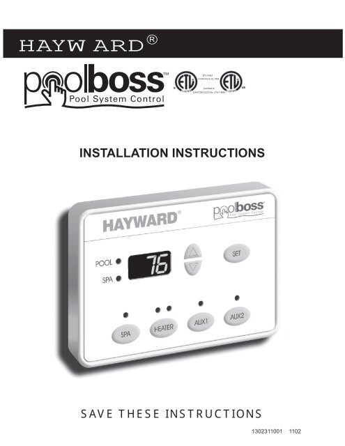
HAYWARD R<br />
ETL listed<br />
Conforms to UL1563<br />
Certified to<br />
CAN/CSA C22.2 No. 218.1-M89<br />
INSTALLATION INSTRUCTIONS<br />
SAVE THESE INSTRUCTIONS<br />
1302311001 1102
TABLE OF CONTENTS<br />
WATER SAFETY INSTRUCTIONS . . . . . . . . . . . . . . . . . . . . . . . . . . . . . . . . . . . . . . . . . . . . 3<br />
ELECTRICAL SPECIFICATIONS . . . . . . . . . . . . . . . . . . . . . . . . . . . . . . . . . . . . . . . . . . . . . . 3<br />
PRODUCT SPECIFICATIONS . . . . . . . . . . . . . . . . . . . . . . . . . . . . . . . . . . . . . . . . . . . . . . . . 4<br />
ELECTRICAL SAFETY INSTRUCTIONS . . . . . . . . . . . . . . . . . . . . . . . . . . . . . . . . . . . . . . . . 5<br />
ELECTRICAL SCHEMATIC . . . . . . . . . . . . . . . . . . . . . . . . . . . . . . . . . . . . . . . . . . . . . . . . . . 5<br />
TYPICAL PLUMBING SCHEMATICS . . . . . . . . . . . . . . . . . . . . . . . . . . . . . . . . . . . . . . . . . . 6-8<br />
INSTALLING THE WATER TEMPERATURE SENSOR . . . . . . . . . . . . . . . . . . . . . . . . . . . . . . 9<br />
INSTALLING THE FREEZE PROTECTION SWITCH . . . . . . . . . . . . . . . . . . . . . . . . . . . . . . . 9<br />
LOCATING & INSTALLING MAIN CONTROL CENTER . . . . . . . . . . . . . . . . . . . . . . . . . . . . .10<br />
LOCATING & INSTALLING MASTER CONTROL PANEL . . . . . . . . . . . . . . . . . . . . . . . . . . .10<br />
TEMPLATE FOR MASTER CONTROL PANEL . . . . . . . . . . . . . . . . . . . . . . . . . . . . . . . . . . . 11<br />
CONNECTING HIGH VOLTAGE COMPONENTS TO THE MAIN CONTROL CENTER . . . 12-14<br />
CONNECTING LOW VOLTAGE COMPONENTS TO THE MAIN CONTROL CENTER . . . 15-16<br />
CONFIGURING THE SYSTEM . . . . . . . . . . . . . . . . . . . . . . . . . . . . . . . . . . . . . . . . . . . . . . . 17<br />
BUTTON FUNCTIONS FOR MASTER PANEL . . . . . . . . . . . . . . . . . . . . . . . . . . . . . . . . . . . 18<br />
BUTTON FUNCTIONS FOR SERVICE PANEL . . . . . . . . . . . . . . . . . . . . . . . . . . . . . . . . . . . 18<br />
INSTALLATION OF OPTIONAL EQUIPMENT . . . . . . . . . . . . . . . . . . . . . . . . . . . . . . . . . . . . 19<br />
2
IMPORTANT WATER SAFETY INSTRUCTIONS<br />
When installing and using these <strong>Control</strong> <strong>System</strong>s, basic safety precautions should always be followed,<br />
including those listed below:<br />
READ AND FOLLOW ALL INSTRUCTIONS<br />
1. WARNING - Risk of Accidental Drowning. Extreme caution must be exercised to prevent unauthorized access by<br />
children. To avoid accidents, ensure that children cannot use the spa or pool to which this <strong>Control</strong> <strong>System</strong> is<br />
connected unless they are closely supervised at all times.<br />
2. DANGER - To reduce the risk of drowning from hair or body entrapment, assure that the suction fittings, skimmers<br />
and main drains in the spa or pool connected to this <strong>Control</strong> <strong>System</strong> are approved for the application.<br />
3. DANGER - To reduce the risk of injury, do not remove the suction fittings or main drain covers. Never operate<br />
the spa or pool if these covers are broken or missing.<br />
4. WARNING - To reduce the risk of injury:<br />
A. The water in a spa to which the <strong>Control</strong> <strong>System</strong> is connected should never exceed 104 F (40 C). Water<br />
temperatures between 100 F (38 C) and 104 F (40 C) are considered safe for a healthy adult. Lower<br />
water temperatures are recommended for young children and when spa use exceeds 10 minutes.<br />
B. Since excessive water temperatures have high potential for causing fetal damage during the early months<br />
of pregnancy, pregnant or possibly pregnant women should limit spa water temperatures to 100 F (38 C).<br />
C. Before entering a spa, the user should measure the water temperature with an accurate thermometer<br />
since the tolerance of water temperature-regulating devices vary.<br />
D. Prolonged immersion in water hotter than 104 F (40 C) may cause hyperthermia. Hyperthermia<br />
occurs when the internal body temperature reaches a level several degrees above normal body<br />
temperatures of 98.6 F (37 C). The symptoms of hyperthermia include dizziness, fainting,<br />
drowsiness, lethargy, and an increase in the internal temperature of the body. The effects of<br />
hyperthermia include:<br />
1. Unawareness of impending hazard. 4. Physical inability to exit the spa.<br />
2. Failure to perceive heat. 5. Fetal damage in pregnant women.<br />
3. Failure to recognize the need to exit 6. Unconsciousness resulting in a danger of<br />
the spa.<br />
drowning.<br />
E. The use of alcohol, drugs, or medication can greatly increase the risk of fatal hyperthermia.<br />
F. Leave the spa immediately if nausea, dizziness or headaches occur, immediately cool the body by<br />
taking a cool shower or by applying cold towels or ice packs. If the symptoms persist, seek medical<br />
attention.<br />
G. The use of alcohol, drugs, or medication before or during spa use may lead to unconsciousness with<br />
the possibility of drowning.<br />
H. Obese persons and persons with a history of heart disease, low or high blood pressure, circulatory<br />
system problems, or diabetes should consult a physician before using a spa.<br />
I. Persons using medication should consult a physician before using a spa since some medication may<br />
induce drowsiness or may affect heart rate, blood pressure, and circulation.<br />
5. Occasional users of the spa should be made aware of these important Safety <strong>Instructions</strong>.<br />
6. WARNING - People with infectious diseases should not use a spa or pool.<br />
7. WARNING - To avoid injury, exercise care when entering and exiting a spa or pool.<br />
8. WARNING - Do not use a spa immediately following strenuous exercise.<br />
9. CAUTION - Maintain water chemistry to provide safe bathing environment.<br />
SAVE THESE INSTRUCTIONS<br />
3
POOL/SPA CONTROL<br />
WITH STANDARD CONTROL CENTER<br />
ITEMS INCLUDED:<br />
PSC2201 CONTROL CENTER<br />
PSC2223 MASTER PANEL<br />
PSC2221 FREEZE PROTECTION KIT<br />
PSC2222 WATER TEMPERATURE SENSOR KIT<br />
PSA24 VALVE ACTUATOR (2 SUPPLIED)<br />
PRODUCT SPECIFICATIONS<br />
POOL/SPA CONTROL<br />
WITH CONTROL CENTER WITH BREAKER BASE<br />
ITEMS INCLUDED:<br />
PSC2202 CONTROL CENTER WITH BREAKER BASE<br />
PSC2223 MASTER PANEL<br />
PSC2221 FREEZE PROTECTION KIT<br />
PSC2222 WATER TEMPERATURE SENSOR KIT<br />
PSA24 VALVE ACTUATOR (2 SUPPLIED)<br />
OPTIONS:<br />
PSC2211<br />
PSC2212<br />
PSC2213<br />
PSC2214<br />
PSA24<br />
3HP RELAY KIT<br />
2HP 2-SPEED RELAY KIT<br />
TIME CLOCK KIT<br />
FIBER OPTICS CONTROL KIT<br />
VALVE ACTUATOR<br />
STANDARD CONTROL CENTER<br />
ITEM #-PSC2201<br />
5"<br />
14 1/2"<br />
CONTROL CENTER WITH BREAKER BASE<br />
ITEM #-PSC2202<br />
5"<br />
14 1/2"<br />
21 3/4"<br />
21-3/4"<br />
CONDUIT KNOCKOUTS<br />
LOW VOLTAGE COMPARTMENT<br />
(2) 1/2" KNOCKOUTS<br />
HIGH VOLTAGE COMPARTMENT<br />
(8) 1/2" / 3/4" CONCENTRIC KNOCKOUTS<br />
(1) 3/4" / 1" CONCENTRIC KNOCKOUT<br />
MASTER CONTROL PANEL<br />
ITEM #-PSC2223<br />
5-7/16"<br />
1-3/8"<br />
3-15/16"<br />
FREEZE PROTECTION SWITCH WATER TEMPERATURE SENSOR VALVE ACTUATORS<br />
ITEM #-PSC2221<br />
ITEM #-PSC2222<br />
ITEM #-PSA24<br />
CABLE LENGTH - 25'<br />
POWER CABLE LENGTH - 10'<br />
4
ELECTRICAL SCHEMATIC<br />
<strong>Control</strong> Center<br />
Circuit Board<br />
Filter Time Clock<br />
Freeze Protection<br />
Switch<br />
Transformer<br />
Cleaner<br />
Actuator<br />
Return<br />
Actuator<br />
Intake<br />
Actuator<br />
<strong>Control</strong> Center<br />
5 5
TYPICAL PLUMBING SCHEMATIC<br />
BASIC POOL/SPA PLUMBING:<br />
These schematics show the necessary plumbing required to operate a pool and a spa that share common<br />
pumps, filters, and heaters. The Motorized Diverter Valves will change position when spa use is desired.<br />
IMPORTANT:<br />
Be sure the valves are synchronized to move simultaneously from pool suction and pool return to the spa<br />
suction and spa return. If they are not synchronized, please follow the instructions below:<br />
1. Reverse the polarity of the wiring to the valve diverter motor that is out of synchronization. The best<br />
way to accomplish this is to reverse the red and white wires inside the valve diverter motor enclosure.<br />
2. Remove the motor enclosure cover, remove the wire nuts, switch the red and white wires, reconnect<br />
the wires with wire nuts, and reinstall cover.<br />
NOTE:<br />
The polarity of the wiring to the valve motor that is out of synchronization can also be reversed by changing<br />
the position of the toggle switch to the reverse position.<br />
If you select this method to reverse polarity, be sure to change the sticker at the rear of the motor enclosure<br />
from the black (Auto-Off-Reverse) sticker to the white (Reverse-Off-Auto) sticker.<br />
You must change the sticker so that users and service personnel know the correct auto position for the valve.<br />
<strong>Pool</strong> / Spa <strong>System</strong><br />
Filter<br />
Pump<br />
Heater<br />
Return<br />
Valve<br />
Actuator<br />
Filter<br />
Water<br />
Sensor<br />
Intake<br />
Valve<br />
Actuator<br />
<strong>Pool</strong><br />
Return<br />
Spa<br />
Return<br />
<strong>Pool</strong> Drain/<br />
Skimmer/<br />
Vacuum Line<br />
Spa Drain/<br />
Skimmer<br />
6
TYPICAL PLUMBING SCHEMATICS<br />
<strong>Pool</strong> / Spa <strong>System</strong> with Pump-Operated Cleaner<br />
Filter<br />
Pump<br />
Heater<br />
Filter<br />
Water<br />
Sensor<br />
Cleaner<br />
Pump<br />
Return<br />
Valve<br />
Actuator<br />
Intake<br />
Valve<br />
Actuator<br />
<strong>Pool</strong><br />
Cleaner<br />
<strong>Pool</strong><br />
Return<br />
Spa<br />
Return<br />
<strong>Pool</strong> Drain/<br />
Skimmer/<br />
Vacuum Line<br />
Spa Drain/<br />
Skimmer<br />
<strong>Pool</strong> / Spa <strong>System</strong> with Valve-<strong>Control</strong>led Cleaner<br />
Filter<br />
Pump<br />
Heater<br />
Filter<br />
Water<br />
Sensor<br />
Cleaner<br />
Valve<br />
Return<br />
Valve<br />
Actuator<br />
Intake<br />
Valve<br />
Actuator<br />
<strong>Pool</strong><br />
Return<br />
<strong>Pool</strong><br />
Cleaner<br />
Spa<br />
Return<br />
<strong>Pool</strong> Drain/<br />
Skimmer/<br />
Vacuum Line<br />
Spa Drain/<br />
Skimmer<br />
7
TYPICAL PLUMBING SCHEMATICS<br />
<strong>Pool</strong> / Spa <strong>System</strong> with Pump-Driven Water Feature<br />
Filter<br />
Pump<br />
Aux<br />
Pump<br />
Heater<br />
Filter<br />
Water<br />
Sensor<br />
Return<br />
Valve<br />
Actuator<br />
Intake<br />
Valve<br />
Actuator<br />
<strong>Pool</strong> Drain/<br />
Skimmer<br />
<strong>Pool</strong><br />
Return<br />
Spa<br />
Return<br />
<strong>Pool</strong> Drain/<br />
Skimmer/<br />
Vacuum Line<br />
Spa Drain/<br />
Skimmer<br />
Water<br />
Feature<br />
Spa Only <strong>System</strong><br />
Heater<br />
Filter<br />
Water<br />
Sensor<br />
Spa<br />
Blower<br />
Spa<br />
Return<br />
Spa Drain/<br />
Skimmer<br />
Spa Air<br />
Injectors<br />
8
INSTALLING TEMPERATURE SENSORS<br />
ATTENTION: The water temperature sensor is 25' long. Consider the sensor<br />
mounting locations BEFORE mounting the Main <strong>Control</strong> Center.<br />
TO INSTALL THE WATER TEMPERATURE SENSOR<br />
1. ATTENTION: Before connecting the temperature sensor wire<br />
to the Main <strong>Control</strong> Center circuit board, the sensor wire must<br />
be inserted through the sensor retaining nut. Insert the sensor<br />
wire through the nut and slide the nut to a poistion adjacent to<br />
the sensing bulb.<br />
2. Locate the Water Temperature Sensor in the discharge<br />
(pressure) line of the filter pump as shown in the Basic<br />
Plumbing Schematic. Drill a .390" (25/64") hole in the pipe and<br />
install the sensor mount on the pipe by tightening the sensor<br />
mount clamp.<br />
3. Install the O-ring onto the Water Temperature Sensor. Slide the<br />
O-ring onto the Water Temperature Sensor so that it is<br />
positioned against the plastic flange on the Water Temperature<br />
Sensor. With the retaining nut and o-ring installed on the Water<br />
Temperature Sensor, insert the Water Temperature Sensor into<br />
the sensor mount and tighten the nut, hand tight only. DO<br />
NOT OVER TIGHTEN.<br />
SENSOR<br />
MOUNT<br />
CLAMP<br />
.390” HOLE<br />
PUMP<br />
DISCHARGE<br />
LINE<br />
RETAINING NUT<br />
WATER TEMPERATURE<br />
SENSOR<br />
O-RING<br />
INSTALLING FREEZE PROTECTION SWITCH<br />
FREEZE PROTECTION FEATURE<br />
If the control senses air temperature of 36 F or lower while the system<br />
is off, the filter pump will turn on. After 30 minutes, the valves will turn to<br />
Spa. After an additional 30 minutes the valves will return to <strong>Pool</strong>. The<br />
cycle will repeat until the control senses an air temperature of 40 F or<br />
higher.<br />
Note: This feature is designed to protect the pool equipment in the<br />
event of unforeseen or unseasonal freezing conditions. It is not<br />
intended to take the place of proper winterizing procedures.<br />
TO INSTALL THE FREEZE PROTECTION SWITCH<br />
SENSOR<br />
FITTING<br />
WASHER<br />
MAIN CONTROL CENTER LOCATION OPTION<br />
1. If the Main <strong>Control</strong> Center is not installed in a building, secure the switch to the outside of the field-installed<br />
electrical conduit directly below the main control center using the cable ties provided.<br />
INSIDE BUILDING LOCATION OPTION<br />
1. If the Main <strong>Control</strong> Center is installed in a building, locate the freeze protection switch so that it will be<br />
exposed to the outside ambient temperature. Secure the switch using the cable ties provided.<br />
2. Provide 2-conductor cable and route it through the wall of the building to the freeze protection. Splice the<br />
wires of the cable to the leads of the switch.<br />
9
LOCATING AND MOUNTING THE MAIN CONTROL CENTER<br />
ATTENTION: POSITIONING THE ENCLOSURE WITH THE CONDUIT KNOCKOUTS<br />
LOCATED AT THE SIDE OR THE TOP OF THE ENCLOSURE MAY ALLOW WATER TO<br />
ENTER THE SYSTEM AND CAUSE DAMAGE TO THE SYSTEM AND/OR CREATE AN<br />
ELECTRICAL SHOCK HAZARD<br />
The Main <strong>Control</strong> Center should be located as close as possible to the pumps, heater, valves, and sensors.<br />
Preferably, the system should mount inside a pool equipment house or other enclosure. However, the system can<br />
be mounted outside. It should mount on a flat vertical wall and be positioned so that the conduit knockouts are<br />
located at the bottom of the enclosure. Remember to consider the length of the wires & valve wires when<br />
selecting the final location. You should also keep in mind that the cable length on the Water Temperature Sensor<br />
is 25' long.<br />
Be sure that the system and all other electrical components are at least 5' from the<br />
edge of the pool or spa. Additionally, the location selected should provide clear<br />
access in front of the system to permit owner or service personnel to stand in front of<br />
the Main <strong>Control</strong> Center unobstructed by other equipment.<br />
INSTALLATION:<br />
After the location has been selected mount the Main <strong>Control</strong> Center. If the<br />
mounting substrate will allow, mount the Main <strong>Control</strong> Center by driving<br />
mounting screws through the holes provided in the back of the enclosure into<br />
the wall. If wall anchors must be used, hold the Main <strong>Control</strong> Center<br />
enclosure in position and mark the hole pattern on the wall. Drill and set the<br />
anchors; fasten the enclosure with screws. Be sure to position the Main<br />
<strong>Control</strong> Center level and square for a neat installation.<br />
LOCATING AND MOUNTING THE MASTER CONTROL PANEL<br />
For maximum convenience, the Master <strong>Control</strong> Panel should be installed inside the home of the user.<br />
However, it can be installed outside. It must be mounted on a vertical surface such as a wall and be located at<br />
eye level for the user. When choosing the location, plan for routing the cable from the <strong>Control</strong> Center to the<br />
Master <strong>Control</strong> Panel.<br />
The cable used to connect the Master <strong>Control</strong> Panel to the <strong>Control</strong> Center must be a 4-conductor, CAT 3, 24<br />
AWG cable. The cable must be field supplied.<br />
Only one Master <strong>Control</strong> Panel can be connected to the <strong>Control</strong> Center.<br />
MOUNTING:<br />
Drill a hole in a hollow wall at a location that will permit the cable to extend through the wall directly behind the<br />
Master Panel. Pull the cable through the hole storing any excess cable in the attic or inside the hollow wall.<br />
Install wall anchors as needed. Use the template included in these instructions to locate the anchors. Install<br />
pan head screws into the anchors and adjust them so that the Master <strong>Control</strong> Panel rests snugly against the<br />
wall when it is installed on the screws. Make wire connections and install on the wall anchor screws.<br />
The cable can also be routed to the Master <strong>Control</strong> Panel along the surface of the wall. For outdoor<br />
installations, be sure to route the cable so that it approaches the panel from the bottom and enters the panel<br />
vertically. Secure the cable to the wall to maintain this cable orientation. This will prevent water from running<br />
down the cable into the Master <strong>Control</strong> Panel.<br />
10
LOCATING AND MOUNTING THE MASTER CONTROL PANEL<br />
CONTINUED<br />
WIRING CONNECTIONS:<br />
Remove the Cover from the Wire Nut Compartment of the Master <strong>Control</strong> Panel.<br />
Connect the wire leads of the Master <strong>Control</strong> Panel to the cable using the Wire Nuts provided.<br />
Place the wire terminations into the Wire Nut Compartment. Route the Cable so that it exits<br />
the compartment through the notch in the compartment’s lower wall. Reinstall the Cover.<br />
The cable must be connected such that the black<br />
lead of the Master Panel is electrically connected<br />
to the TX terminal of the <strong>Control</strong> Center, the yellow<br />
lead is connected to the RX terminal, the green lead<br />
is connected to the GND terminal, and the red lead is<br />
connected to the V+ terminal.<br />
3-1/2"<br />
Hollow<br />
Wall<br />
Wire Nuts<br />
Wire Nut<br />
Compartment<br />
Note: Use of a CAT 3 Cable with black, yellow, green,<br />
and red insulated conductors will make it easier to<br />
make the proper connections. CAT 3 cables intended<br />
for telephone wiring will use these colors. Just simply<br />
connect like colors of the cable to like colors of the<br />
Master Panel, and then connect the proper colored<br />
wire to proper terminal of the <strong>Control</strong> Center.<br />
Panel Position<br />
Field Wiring<br />
Key Slots for<br />
Hanging<br />
USE THIS FULL SIZED TEMPLATE FOR CORRECT POSITIONING OF<br />
MASTER CONTROL PANEL ON WALL<br />
11
HIGH VOLTAGE CONNECTIONS<br />
All electrical equipment must be installed five feet or more from pool or spa. Make sure that the motors on<br />
equipment have built-in thermal protection. Bond all equipment including the <strong>Control</strong> Center to earth ground.<br />
Determine the number and sizes of conductors, the number of conduit runs, and the sizes of the conduit<br />
needed for the installation. See Wiring Information Table for wire size recommendations.<br />
Standard <strong>Control</strong> Center<br />
At the equipment site, install an electrical supply panel with independent breakers for each separate piece of<br />
equipment and for the system power supply. A ground-fault circuit breaker is required to protect an<br />
underwater lighting circuit. The electrical supply panel should be readily accessible to the spa user, but<br />
installed at least five feet from pool or spa.<br />
Open door, and remove deadfront cover from <strong>Control</strong> Center to expose high voltage compartment. Knockout<br />
the appropriate holes at the bottom of the high voltage compartment of the <strong>Control</strong> Center enclosure. Run<br />
electrical conduit from lower side of <strong>Control</strong> Center to the supply panel and from <strong>Control</strong> center to each piece<br />
of equipment. Pull the appropriate wire.<br />
Connect the system power leads to supply conductors using wire nuts.<br />
For each piece of 240-volt equipment, connect the<br />
supply conductors to LINE1 and LINE2 terminals of<br />
Terminal Wire Size Ratings<br />
a relay, and connect the equipment conductors<br />
Terminal<br />
Allowable Wire Size Range<br />
to the LOAD1 and LOAD2 terminals of the relay.<br />
Tighten relay terminal screws to the torque listed in<br />
Relay<br />
10 – 14 AWG<br />
the wiring information table.<br />
Main & Neutral Lugs<br />
2 – 14 AWG<br />
For each piece of 120-volt equipment, connect the<br />
120-volt supply conductor to LINE1 terminal of the<br />
relay and connect the 120-volt equipment conductor<br />
Neutral Bar<br />
Equipment Ground<br />
4 - 14 AWG<br />
4 - 14 AWG<br />
to the LOAD1 terminal relay. Tighten relay terminal screws to the torque listed in the wiring information table.<br />
Connect ground wires to equipment ground.<br />
<strong>Control</strong> Center<br />
Circuit Board<br />
Time Clock<br />
Transformer<br />
Relay<br />
Equipment Ground<br />
STANDARD CONTROL CENTER<br />
High Voltage Compartment<br />
12
HIGH VOLTAGE CONNECTIONS<br />
HIGH VOLTAGE CONNECTIONS - CONTINUED<br />
<strong>Control</strong> Center with Breaker Base<br />
Open door, and remove deadfront cover from <strong>Control</strong> Center to expose high voltage compartment.<br />
Knockout the appropriate holes at the bottom of the high voltage compartment of the <strong>Control</strong> Center<br />
enclosure. Run electrical conduit from lower side of <strong>Control</strong> Center to the supply panel and from the<br />
<strong>Control</strong> center to each piece of equipment. Pull the appropriate wire.<br />
Connect the voltage conductors to main lugs of breaker base, and the neutral conductor to neutral lug of<br />
the breaker base. Connect the ground wire to equipment ground. Tighten terminals to the torques listed<br />
in the Wiring Information Table.<br />
Install a separate 1-pole circuit breaker to power the system. Connect the black system power lead to the<br />
circuit breaker and the white lead to the neutral bar of the breaker base.<br />
Install a 1-pole circuit breaker for each piece of 120-volt equipment and a 2-pole circuit breaker for each<br />
piece of 240-volt equipment. Circuit breaker models suitable for installation are listed in the Suitable<br />
Circuit Breaker Table.<br />
For each piece of 240-volt equipment, run an appropriately sized wire from the load terminals of the<br />
circuit breaker to LINE1 and LINE2 terminals of a relay. Connect the equipment conductors to the<br />
LOAD1 and LOAD2 terminals of the relay. Tighten relay terminal screws to the torque listed in the wiring<br />
information table.<br />
For each piece of 120-volt equipment, run an appropriately sized wire from the circuit breaker to the<br />
LINE1 terminal of a relay. Connect the 120-volt equipment conductor to the LOAD1 terminal of the relay.<br />
Tighten the relay terminal screws to the torque listed in the Wiring Information Table. Connect the<br />
equipment neutral conductor to the neutral bar of the breaker base.<br />
Connect ground wires to equipment ground.<br />
13
HIGH VOLTAGE CONNECTIONS HIGH VOLTAGE STANDARD CONNECTIONS CONTROL CENTER<br />
Low voltage compartment<br />
(do not run high voltage<br />
in this compartment)<br />
Transformer<br />
Service Panel<br />
Line 1<br />
Load 1<br />
Filter Pump<br />
(240VAC)<br />
HIGH VOLTAGE CONNECTIONS CONTROL CENTER<br />
WITH BREAKER BASE<br />
Transformer<br />
Circuit Breaker<br />
Base<br />
Neutral<br />
Neutral<br />
Filter Pump Aux 1 Aux 2<br />
Line 2<br />
Load 2<br />
Blower<br />
(120VAC)<br />
Power Supply<br />
240 VAC / 60 HZ<br />
3-wire plus ground<br />
Low voltage compartment<br />
(do not run high voltage<br />
in this compartment)<br />
Filter Pump Aux 1 Aux 2<br />
Filter Pump<br />
(240VAC)<br />
Line 1<br />
Load 1<br />
Line 2<br />
Load 2<br />
Blower<br />
(120VAC)<br />
Power Supply<br />
240 VAC / 60 HZ<br />
3-wire plus ground<br />
14
LOW VOLTAGE CONNECTIONS<br />
Open <strong>Control</strong> Center door, and remove deadfront cover to expose low voltage compartment.<br />
Knockout the appropriate holes at the bottom of the low voltage compartment.<br />
Connecting Valve Actuators<br />
Run the cables from the Valve Actuators to the <strong>Control</strong> Center. Route the cables through the<br />
knockout into the low voltage compartment. Plug the Intake Valve Actuator into the socket on<br />
the circuit board labeled INTAKE, and the Return Valve Actuator into the socket labeled RET. If<br />
a Cleaner Valve Actuator is used, plug it into the socket labeled CLN. Store excess<br />
cable in the low voltage compartment. Check the synchronization<br />
of the valves when the system is powered up. See the Valve Actuator<br />
<strong>Installation</strong> <strong>Instructions</strong> for synchronization instructions.<br />
Connecting the Water Temperature Sensor<br />
Run the cable from the Water Temperature Sensor to<br />
the <strong>Control</strong> Center. Route the cable through the knockout<br />
into the low voltage compartment. Connect the cable<br />
to the screw terminals on the circuit board labeled TEMP.<br />
Connecting the Freeze Protection Switch<br />
Run the cable from the Freeze Protection Switch to the<br />
<strong>Control</strong> Center. Route the cable through the knockout into<br />
the low voltage compartment. Connect the cable to the<br />
screw terminals on the circuit board labeled FREEZE.<br />
Low Voltage<br />
Connections<br />
Master Panel<br />
Water Tenperature Sensor<br />
Freeze Protection Switch<br />
Heater<br />
Cleaner Actuator<br />
Return Actuator<br />
Intake Actuator<br />
Connecting the Master Panel<br />
Run a 4-conductor, CAT 3, 24AWG cable from the<br />
Master Panel to the <strong>Control</strong> Center. Route the cable<br />
through the knockout into the low voltage compartment.<br />
Connect the cable to the screw terminals on the circuit<br />
board. The cable must be connected such that the black<br />
lead of the Master Panel is electrically connected to the<br />
terminal labeled TX, the yellow lead is connected to the<br />
RX terminal, the green lead is connected to the GND<br />
terminal, and the red lead is connected to the V+ terminal.<br />
Neutral Bar<br />
Low Voltage<br />
Compartment<br />
Neutal Lug<br />
Main Lugs<br />
Breaker Base<br />
CONTROL CENTER WITH BREAKER BASE<br />
Heater Connection Guidelines<br />
The <strong>Control</strong> Center provides a means for controlling heaters that utilize millivolt ignition systems<br />
as well as 24v ignition systems. Do not connect high voltage heaters to the low voltage heater<br />
terminals.<br />
Run a 2-Conductor, 22 AWG cable from the heater to the <strong>Control</strong> Center. Connect the cable to<br />
the heater in accordance with the Heater’s Manufacturer’s <strong>Instructions</strong>.<br />
Route the cable through the knockout into the low voltage compartment. Connect the cable to<br />
the screw terminals on the circuit board labeled HEATER.<br />
15
LOW VOLTAGE CONNECTIONS<br />
Master Panel<br />
TX<br />
RX<br />
GND<br />
V+<br />
TEMP<br />
FREEZE<br />
HEAT<br />
<strong>Control</strong> Center<br />
CLN<br />
RET<br />
BK<br />
(TX)<br />
Y<br />
(RX)<br />
G<br />
(GD)<br />
R<br />
(V+)<br />
INTAKE<br />
Freeze<br />
Protection<br />
Switch<br />
Filter<br />
Pump<br />
Heater<br />
Return<br />
Valve<br />
Actuator<br />
Filter<br />
Water<br />
Sensor<br />
Intake<br />
Valve<br />
Actuator<br />
<strong>Pool</strong><br />
Return<br />
Spa<br />
Return<br />
<strong>Pool</strong> Drain/<br />
Skimmer/<br />
Vacuum Line<br />
Spa Drain/<br />
Skimmer<br />
16
CONFIGURING HIGH VOLTAGE THE CONNECTIONS<br />
SYSTEM<br />
Relays<br />
Before powering up system, verify that each relay is wired to the proper connector on the <strong>Control</strong> Center<br />
Circuit Board. For example, verify that the relay that the filter pump is wired to is plugged into the filter<br />
pump socket. Use the electrical schematic as a guide.<br />
Dip Switch Positions<br />
The circuit board in the <strong>Control</strong><br />
Center is equipped with dip<br />
switches. These switches can<br />
be set to configure the system<br />
for specific output configurations.<br />
Be sure to review these switch<br />
positions before power-up to<br />
ensure that the system will<br />
respond properly.<br />
DIP SWITCH IDENTIFICATION<br />
1 - AUX2 / CLNR<br />
2 - AUX2 / OPTICS<br />
3 - OPTIONAL TIME CLOCK / CLNR<br />
4 - OPTIONAL TIME CLOCK / AUX1<br />
5 - CLOCK / SPA<br />
6 - HEATER COOLDOWN<br />
Aux 2 Configuration<br />
Switch<br />
Two switches are available for<br />
configuring the Aux 2 function.<br />
One switch is labeled CLNR,<br />
and the second switch is labeled<br />
OPTICS. Only one of the<br />
two switches should be in<br />
the down position. If both switches are in the down position, OPTICS switch will override the CLNR<br />
(Cleaner) switch. Both switches can be in up position.<br />
CLNR & OPTICS in UP position: Aux 2 function will control Aux 2 relay.<br />
CLNR in DOWN position: Aux 2 function will control the Cleaner relay and Cleaner actuator.<br />
OPTICS in DOWN position: Fiber Optics <strong>Control</strong> Kit is installed. Aux 2 function will control lamp<br />
and color wheel outputs of the Fiber Optics <strong>Control</strong> Kit.<br />
Optional Time Clock Configuration Switch<br />
Three switches are available for controlling the function of the optional time clock.<br />
CLNR switch in DOWN position: Optional Time Clock will control the Cleaner relay and Cleaner<br />
actuator.<br />
AUX 1 switch in DOWN position: Optional Time Clock will control Aux 1 function.<br />
SPA switch in DOWN position: Optional Time Clock will control SPA function.<br />
Note that the optional Time Clock can control two or more functions simultaneously. For example, if the<br />
Spa and Aux 1 switches are in the down position, the optional time clock will control the Spa and Aux 1<br />
functions.<br />
Heater Cool Down Configuration Switch<br />
COOL DOWN in DOWN position: If the Heater is enabled, the filter pump is kept running for<br />
5 minutes after Spa is turned off, or after the filter pump time clock turns off.<br />
COOL DOWN in UP position: Heater Cool Down is disabled.<br />
17
BUTTON FUNCTIONS FOR MASTER PANEL<br />
Set Point Adjustment Key - The up or down arrow keys are used to adjust the spa<br />
or pool set point temperatures. To adjust a set point, the current set point must be displayed.<br />
Use the Set Point Selection key to display the set point to be adjusted. Each set point can<br />
be set anywhere between 50 F and 104 F.<br />
Set Point Selection Key - For each press of the Set key, the display will change<br />
successively from water temperature, to spa set point, to pool set point. The spa LED<br />
will illuminate to indicate the spa set point is being displayed. The pool LED will illuminate<br />
to indicate that the pool set point is being displayed.<br />
Spa Key - Pressing the spa key will turn on the intake and return valves to circulate water<br />
through the spa. If the filter pump is off, it will be turned on. The display will show the spa<br />
water temperature.<br />
Heater Enable Key - Pressing this key will enable the heater for heating. The yellow heater<br />
LED will illuminate when the heater is enabled. The green heater LED will illuminate<br />
when the heater is on.<br />
Aux 1 Key - Pressing this key will turn the Aux 1 feature on. The Aux 1 LED illuminates<br />
when the feature is on.<br />
Aux 2 Key<br />
(a) CLNR & OPTICS dip switches in UP position - Pressing this key will turn the Aux 2<br />
feature on. The Aux 2 LED illuminates when the feature is on.<br />
(b) CLNR in DOWN position - Pressing this key will turn the Cleaner features on. The<br />
Aux 2 LED illuminates when the feature is on.<br />
(c) OPTICS in DOWN position (Fiber Optics <strong>Control</strong> Kit is installed) - Pressing this key<br />
will turn lamp feature on. Aux 2 LED illuminates when lamp is on. Pressing this key a<br />
second time will turn the lamp off. Pressing this key and holding it for 3 seconds will turn<br />
lamp and color wheel features on. Aux 2 LED will blink when lamp and color wheel are<br />
on. Pressing this key a second time will turn the color wheel off. Pressing it a third time<br />
will turn the lamp off.<br />
CONTROL CENTER OVERRIDE SWITCH FUNCTIONS<br />
Filter - Off<br />
Keeps filter pump off. Filter pump<br />
cannot be turned on by spa key of<br />
master panel, time clock, cleaner<br />
selection, or by freeze protection<br />
switch.<br />
Filter - Auto<br />
Allows for automatic control of filter<br />
pump by time clock, freeze protection<br />
switch, cleaner selection, or spa<br />
selection.<br />
Filter - Manual<br />
Keeps filter pump on. Filter pump<br />
cannot be turned off by spa key of<br />
master panel, time clock, cleaner<br />
selection, or by freeze protection<br />
switch.<br />
18<br />
Valves - Auto<br />
Allows for automatic control of<br />
actuators from master panel.<br />
Valves - Spa<br />
Turns intake and return valves to<br />
spa position, but does not turn on<br />
pump<br />
Valves - Drain<br />
Turns intake valve (taking water<br />
from the spa) but not the return<br />
valve.<br />
Valves - Fill<br />
Turns return valve adding water<br />
to the spa) but not the intake<br />
valve.
INSTALLATION OF OPTIONAL EQUIPMENT<br />
3HP Relay kit (PSC2211)<br />
The <strong>Control</strong> Center comes equipped with 3 relays installed. An optional 4th relay can be installed in the<br />
<strong>Control</strong> Center. This relay can be used to control a Cleaner Pump or a High Voltage Heater.<br />
To install the relay, open <strong>Control</strong> Center door, and remove deadfront cover to expose the high voltage<br />
compartment. Mount the relay in the high voltage compartment in the mounting holes provided. Route<br />
the relay harness through the bushing in the upper wall of the high voltage compartment into the low<br />
voltage compartment.<br />
For control of a cleaner, plug the relay harness into the CLNR socket on the <strong>Control</strong> Center Circuit<br />
Board. For control of a high voltage heater, plug the relay into the HV HEATER socket.<br />
Time Clock Kit (PSC2213)<br />
A second time clock can control the spa switchover, the aux 1 circuit, the pool cleaner pump or cleaner<br />
valve actuator. Refer to the instructions for "Configuring the <strong>System</strong>" that are included in these<br />
instructions.<br />
To install the optional time clock, open <strong>Control</strong> Center door, and remove deadfront cover. Remove the<br />
plastic plug from the deadfront cover. Mount the optional Time next to the Filter Pump Time Clock. Plug<br />
the Time Clock Harness into Optional Clock socket on the <strong>Control</strong> Center Circuit Board.<br />
OPTIONAL<br />
TIME CLOCK<br />
3 HP RELAY<br />
19
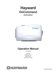
<strong>Hayward</strong> <strong>Pool</strong> Products Worldwide Locations<br />
<strong>Hayward</strong> Corporate Headquarters<br />
<strong>Hayward</strong> <strong>Pool</strong> Products, Inc.<br />
900 Fairmont Avenue<br />
Elizabeth, NJ 07207, USA<br />
Tel: 908-351-5400<br />
Fax: 908-351-5675<br />
<strong>Hayward</strong> <strong>Pool</strong> Products, Inc.<br />
2875 Pomona Boulevard<br />
Pomona, CA 91768, USA<br />
Tel: 909-594-1600<br />
Fax: 909-598-6905<br />
<strong>Hayward</strong> Iberica S.A.<br />
Carretera Nacional III, KM 333, 7 Nave 2<br />
E-46930 Quart De Poblet, Valencia, SPAIN<br />
Tel: 34 6 152 3454<br />
Fax: 34 6 152 3357<br />
<strong>Hayward</strong>/IMG<br />
International Marketing Group<br />
801 Corporate Center Drive, Suite 110<br />
Pomona, CA 91768, USA<br />
Tel: 909-620-4041<br />
Fax: 909-620-1249<br />
<strong>Hayward</strong> <strong>Pool</strong> Products Canada, Inc.<br />
2880 Plymouth Drive<br />
Oakville, Ontario, CANADA L6H 5R4<br />
Tel: 905-829-2880<br />
Fax: 905-829-3636<br />
<strong>Hayward</strong> <strong>Pool</strong> Europe<br />
ZA de l'Observatoire<br />
2, Avenue des Chaumes<br />
78182 St. Quentin en Yvelines Cedex, FRANCE<br />
Tel: 33 1 39 30 91 00<br />
Fax: 33 1 39 30 91 89<br />
FOR FURTHER INFORMATION OR CONSUMER TECHNICAL SUPPORT, PLEASE CALL 866-772-2100<br />
OR VISIT OUR WEB SITE AT WWW.HAYWARDNET.COM