Power-Flo LX Owners Manual - Pool Center
Power-Flo LX Owners Manual - Pool Center
Power-Flo LX Owners Manual - Pool Center

Create successful ePaper yourself
Turn your PDF publications into a flip-book with our unique Google optimized e-Paper software.
ISPF SERIES<br />
Rev. C<br />
_____________________________________________________________________________________<br />
OWNER’S MANUAL<br />
INSTALLATION, OPERATION, & PARTS<br />
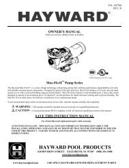
<strong>Power</strong>-<strong>Flo</strong> <strong>LX</strong> / <strong>Power</strong>-<strong>Flo</strong> II Pump Series<br />
The Hayward ® <strong>Power</strong>-<strong>Flo</strong> <strong>LX</strong> and <strong>Power</strong>-<strong>Flo</strong> II Pump Series are specifically engineered for the demanding requirements<br />
of today’s above-ground swimming pools. The advanced design reduces maintenance requirements while providing superior<br />
performance.<br />
To prevent potential injury and to avoid unnecessary service calls, read this manual carefully and completely.<br />
CAUTION – We highly recommend a qualified professional install and service this product.<br />
WARNING – This manual contains important safety information that must be furnished to the end<br />
user of this product. FAILURE TO READ AND FOLLOW ALL INSTRUCTIONS COULD RESULT<br />
IN SERIOUS INJURY.<br />
*Only units equipped with 3' twist-lock cords<br />
or furnished without a cord for permanent<br />
wiring are UL-Listed.<br />
SAVE THIS INSTRUCTION MANUAL<br />
HAYWARD POOL PRODUCTS, INC.<br />
Corporate Headquarters:<br />
U.S.A:<br />
620 Division Street 1 Hayward Industrial Drive 2935 Sidco Drive 2875 Pomona Blvd.<br />
Elizabeth, NJ 07207 Clemmons, NC 27012 Nashville, TN 37204 Pomona, CA 91768<br />
Canada:<br />
Europe:<br />
2880 Plymouth Drive Parc Industriel de la plaine de l'ain<br />
Oakville, Ontario L6H 5R4<br />
Allêe des chênes<br />
01150 St Vulbas<br />
France
<strong>Power</strong>-<strong>Flo</strong> <strong>LX</strong> / <strong>Power</strong>-<strong>Flo</strong> II Pump Series<br />
___________________________________________<br />
PRODUCT REGISTRATION<br />
(Retain For Your Records)<br />
DATE OF INSTALLATION ____________________<br />
INITIAL PRESSURE GAUGE READING (CLEAN FILTER)<br />
_______________________<br />
PUMP MODEL ________________ HORSEPOWER _______________________<br />
FILTER MODEL ________________<br />
SERIAL NUMBER _______________________<br />
IMPORTANT SAFETY INSTRUCTIONS<br />
When installing and using this electrical equipment, basic safety precautions should always be<br />
followed, including the following: Failure to follow instructions may result in injury.<br />
READ AND FOLLOW ALL INSTRUCTIONS<br />
IN THIS OWNER’S MANUAL AND ON<br />
EQUIPMENT.<br />
KEEP SAFETY LABELS IN GOOD CONDITION AND<br />
REPLACE IF MISSING OR DAMAGED.<br />
WARNING – To reduce risk of injury, do not permit children to use or climb on this<br />
product. The ANSI/NSPI 4 Standard (above-ground and on-ground pools) advises that<br />
components such as the filtration system, pumps, and heaters be positioned to prevent their being<br />
used as a means of access to the pool by young children. Closely supervise children at all times.<br />
CAUTION – The <strong>Power</strong>-<strong>Flo</strong> <strong>LX</strong> / <strong>Power</strong>-<strong>Flo</strong> II Pump Series' are intended for use on<br />
permanently installed above-ground swimming pools and may also be used with hot tubs and spas<br />
if so marked. Do NOT use with storable pools. A permanently installed pool is constructed in or<br />
on the ground or in a building such that it cannot be readily disassembled for storage. A storable<br />
pool is constructed so that it is capable of being readily disassembled for storage and reassembled<br />
to its original integrity.<br />
Though this product is designed for outdoor use, it is strongly advised to protect the electrical<br />
components from the weather. Select a well-drained area, one that will not flood when it rains. It<br />
requires free circulation of air for cooling. Do not install in a damp or non-ventilated location.<br />
Bond motor to pool structure. Use a solid copper conductor, size or larger. Run wire from<br />
external bonding lug to reinforcing rod or mesh. Connect a No. 8 AWG (8.4 mm²) solid copper<br />
bonding wire to the pressure wire connector provided on the motor housing and to all metal parts<br />
of swimming pool, spa, or hot tub, and to all electrical equipment, metal piping or conduit within<br />
5 ft. (1.5 m) of inside walls of swimming pool, spa, or hot tub. (In Canada use No. 6 AWG<br />
bonding wire.)
<strong>Power</strong>-<strong>Flo</strong> <strong>LX</strong> / <strong>Power</strong>-<strong>Flo</strong> II Pump Series __________<br />
____________<br />
NOTE: The National Electrical Code (NEC) permits use of a cord with a maximum 3 ft.<br />
(1 m) length. If your pump is equipped with a cord complying with the NEC, the following three<br />
(3) items apply.<br />
WARNING – Risk of Electric Shock. Connect only to a grounding<br />
type receptacle protected by a Ground Fault Circuit Interrupter (GFCI). Contact a<br />
qualified electrician if you cannot verify that the receptacle is protected by a<br />
GFCI.<br />
WARNING – To reduce the risk of electric shock replace damaged cord<br />
immediately. Do NOT bury cord. Locate cord to minimize abuse from lawn<br />
mowers, hedge trimmers and other equipment.<br />
WARNING – To reduce the risk of electric shock, do NOT use an extension cord to<br />
connect unit to electric supply. Provide a properly located outlet. Qualified personnel MUST do<br />
all electrical wiring.<br />
CAUTION – All suction and discharge valves MUST be OPEN when<br />
starting the filter system. Failure to do so could result in severe personal injury<br />
and/or property damage. All drains and suction covers MUST have properly<br />
installed covers securely attached with the screws supplied with the covers. If<br />
screws are lost, order replacement parts from your supplier.<br />
DANGER – Suction Entrapment Hazard. Never use the pool or<br />
spa if a drain cover is damaged, cracked, missing, or not securely attached. Suction in drains and<br />
suction outlets can cause drowning, disembowelment, hair or body entrapment, severe injury, and<br />
death. Disembowelment, entrapment, or drowning is possible when body parts or hair come in<br />
contact with damaged, broken, cracked, missing, or unsecured drain covers and suction outlets.<br />
Suction from pumps with only one drain or suction outlet can cause disembowelment,<br />
entrapment, or drowning. Pumps for pools and spas require two (2) functioning suction outlets at<br />
least three (3) feet apart, on two (2) walls or on the floor and one (1) wall of the pool or spa.<br />
Installation of pump and suction outlets must be in compliance with all applicable local building<br />
codes. Replace damaged, broken, cracked, missing, or unsecured drain covers and suction outlets<br />
immediately.<br />
WARNING – Hazardous Pressure. Pumps, filters, and other<br />
equipment/components of a swimming pool filtration system operate under pressure. Incorrectly<br />
installed and/or improperly tested filtration equipment and/or components may fail resulting in<br />
injury and/or property damage. A qualified pool professional MUST conduct all pressure tests.<br />
This product is intended for above-ground/on-ground swimming pool applications only. Do NOT<br />
connect to a high-pressure system such as a municipal water main. To prevent explosion caused<br />
by entrapped air in the filtration system use provided air relief valve to bleed air from the system.<br />
Confirm that ALL filtration system component clamps, bolts, and covers have been tightened to<br />
the manufacturer’s recommendations.<br />
WARNING – Never operate or test the filtration system at more than 30 PSI.<br />
SAVE THESE INSTRUCTIONS
<strong>Power</strong>-<strong>Flo</strong> <strong>LX</strong> / <strong>Power</strong>-<strong>Flo</strong> II Pump Series<br />
___________________________________________<br />
Installation Instructions<br />
Pump Location<br />
The <strong>Power</strong>-<strong>Flo</strong> <strong>LX</strong> pump MUST be installed below the<br />
pool water line (see Figure to right).<br />
Self-priming <strong>Power</strong>-<strong>Flo</strong> II pumps may be installed up to<br />
four (4) feet above the pool water line.<br />
Install pump on a firm, level base or pad to meet all local<br />
and national codes. The field supplied base or pad must<br />
be level and vibration-free.<br />
Pump motors require free circulation of air for cooling.<br />
Do NOT install pump in a damp or non-ventilated<br />
location.<br />
Though the pump is designed for outdoor use, it is strongly advised to protect the electrical components from the<br />
weather. Select a well-drained area, one that will not flood when it rains.<br />
Pump Mounting<br />
Fasten pump to base or pad with screws or bolts to further reduce vibration and stress on pipe or hose joints. The base<br />
MUST be solid - level - rigid - vibration free.<br />
Plumbing<br />
Pump mount must:<br />
• Allow pump inlet height to be as close to water level as possible.<br />
• Allow use of short, direct suction pipe (to reduce friction losses).<br />
• Allow for ball valves in suction and outlet piping.<br />
• Be protected from excess moisture and flooding.<br />
• Allow adequate access for servicing pump and piping.<br />
Use Teflon tape to seal threaded connections on molded plastic components. All plastic fittings must be new or<br />
thoroughly cleaned before use. NOTE: Do NOT use Plumber’s Pipe Dope as it may cause cracking of the plastic<br />
components.<br />
When applying Teflon tape to plastic threads, wrap the entire threaded portion of the male fitting with one to two<br />
layers of tape. Wind the tape clockwise as you face the open end of the fitting, beginning at the end of the fitting.<br />
The pump suction and outlet ports have molded-in thread stops. Do NOT attempt to force hose connector fitting past<br />
this stop. It is only necessary to tighten fittings enough to prevent leakage. Tighten fitting by hand and then use a tool<br />
to engage fitting an additional 1 ½ turns. Use care when using Teflon tape as friction is reduced considerably; do<br />
NOT over-tighten fitting or you may cause damage. If leaks occur, remove connector, clean off old Teflon tape, rewrap<br />
with one to two additional layers of Teflon tape, and re-install connector.<br />
Piping - Flexible Hose, PVC, or Reinforced Hose are all acceptable piping methods<br />
For pump outlet use 1-1/2" PVC pipe or reinforced hose. For pump suction on ALL models, use 1-1/2" reinforced<br />
hose. Increase size if a long run is needed. For pipe larger than port, use reducing fitting in strainer port.<br />
To avoid pump strain, support suction and outlet independently. Place supports near pump. To avoid strain left by a<br />
gap at last connection, start all piping at pump and run pipe AWAY from pump.<br />
NEVER use suction pipe SMALLER than pump suction connections. Suction pipe inlet must be lower than pump<br />
inlet port.
<strong>Power</strong>-<strong>Flo</strong> <strong>LX</strong> / <strong>Power</strong>-<strong>Flo</strong> II Pump Series_____________________________________________<br />
Installation Instructions (cont.)<br />
Fittings<br />
Fittings restrict flow. For better efficiency, use the fewest possible fittings. Avoid fittings that could cause an air trap.<br />
<strong>Pool</strong> and spa fittings MUST conform to the International Association of Plumbing and Mechanical Officials (IAPMO)<br />
standards.<br />
Use a non-entrapping suction fitting in pool or double suction (skimmer and main drain).<br />
Electrical<br />
WARNING – Ground motor before connecting to electrical power supply.<br />
Failure to ground pump motor can cause serious or fatal electrical shock hazard.<br />
WARNING – Do NOT ground to a gas supply line.<br />
WARNING – To avoid dangerous or fatal electrical shock, turn OFF power to<br />
motor before working on electrical connections.<br />
WARNING – Ground Fault Circuit Interrupter (GFCI) tripping indicates<br />
electrical problem. If GFCI trips and won’t reset, consult electrician to inspect and repair electrical<br />
system.<br />
WARNING – Fire Hazard. Match supply voltage to motor nameplate voltage.<br />
Insure that the electrical supply available agrees with the motor’s voltage, phase, and cycle, and that the wire size is<br />
adequate for the H.P. (KW) rating and distance from the power source.<br />
NOTE: All electrical wiring MUST be performed by a qualified professional, and MUST conform to local<br />
codes and regulations.<br />
Voltage<br />
Voltage at motor MUST NOT be more than 10% above or below motor name plate rated voltage, or motor<br />
may overheat, causing overload tripping and reduced component life. If voltage is less than 90% or more<br />
than 110% of rated voltage when motor is running at full load, consult power company.<br />
Grounding/Bonding<br />
Install, ground, bond, and wire motor according to local or national electrical code requirements.<br />
Permanently ground motor. Use green ground terminal provided under motor canopy or access place; use<br />
size and type wire required by code. Connect motor ground terminal to electrical service ground.<br />
Bond motor to pool structure. Use a solid copper conductor, size or larger. Run wire from external bonding<br />
lug to reinforcing rod or mesh. Connect a No. 8 AWG (8.4 mm 2 ) solid copper bonding wire to the pressure<br />
wire connector provided on the motor housing and to all metal parts of swimming pool, spa, or hot<br />
tub, and to all electrical equipment, metal piping or conduit within 5 ft. (1.5 m) of inside walls of swimming<br />
pool, spa, or hot tub.<br />
Wiring<br />
Pump MUST be permanently connected to circuit. If other lights or appliances are also on the same circuit,<br />
be sure to add their amp loads before figuring wire and circuit breaker sizes. (NOTE: If unsure how to do<br />
this or if this is confusing, consult a licensed electrician). Use the load circuit breaker as the Master On-Off<br />
switch.<br />
Install a Ground Fault Circuit Interrupter (GFCI) in circuit; it will sense a short-circuit to ground and<br />
disconnect power before it becomes dangerous to pool users. For size of GFCI required and test procedures<br />
for GFCI, see manufacturer’s instructions.
<strong>Power</strong>-<strong>Flo</strong> <strong>LX</strong> / <strong>Power</strong>-<strong>Flo</strong> II Pump Series<br />
___________________________________________<br />
Installation Instructions (cont.)<br />
Electrical (cont.)<br />
Wiring (cont.)<br />
In case of a power outage, check GFCI for tripping, which will prevent normal pump operation. Reset if<br />
necessary.<br />
NOTE: If you do not use conduit when wiring motor, be sure to seal wire opening on end of<br />
motor to prevent dirt, bugs, etc., from entering.<br />
New Installation – Start-Up & Operation<br />
Prior to Start-Up<br />
Fill strainer housing with water to suction pipe level. NEVER operate the pump without water. Water acts as a<br />
coolant and lubricant for the mechanical shaft seal.<br />
WARNING – NEVER run pump dry. Running pump dry may damage seals, causing leakage<br />
and flooding. Fill strainer housing with water before starting motor.<br />
CAUTION – Do NOT add chemicals to pool/spa system directly in front of pump suction.<br />
Adding undiluted chemicals may damage pump and voids warranty.<br />
CAUTION – Before removing strainer cover:<br />
1. STOP PUMP before proceeding.<br />
2. CLOSE VALVES in suction and outlet pipes.<br />
3. RELEASE ALL PRESSURE from pump and piping system.<br />
Priming Pump<br />
WARNING – If pump is being pressure tested, be sure pressure has been<br />
released before removing strainer cover.<br />
WARNING – Do NOT block pump suction. To do so with body may cause<br />
fatal injury. Small children using pool MUST always have close adult supervision.<br />
• Open all valves before starting system.<br />
• Release all air from filter and piping system. See filter owner’s manual.<br />
• When water source is higher than the pump, pump will prime itself when suction and outlet valves are opened. If<br />
water source is lower than the pump, unscrew and remove strainer cover; fill strainer and pump with water.<br />
• Clean and lubricate strainer cover O-ring with "Jack's 327" each time it is removed.<br />
• Clean and inspect O-ring; re-install on strainer cover.<br />
• Replace strainer cover on strainer housing; turn clockwise to tighten cover.<br />
NOTE: Tighten strainer cover by hand only (no wrenches) ¼ turn.<br />
Pump should prime. Priming time will depend on vertical length of suction lift and horizontal length of suction pipe.<br />
If pump does NOT prime within ten minutes, stop motor and determine cause. Be sure all suction and discharge<br />
valves are open when pump is running. See Troubleshooting Guide.
<strong>Power</strong>-<strong>Flo</strong> <strong>LX</strong> / <strong>Power</strong>-<strong>Flo</strong> II Pump Series<br />
___________________________________________<br />
Storage/Winterization<br />
WARNING – Explosion Hazard. Purging the system with compressed air can cause<br />
components to explode, with risk of severe injury or death to anyone nearby. Use only a low<br />
pressure (below 5 PSI), high volume blower when air purging the pump, filter, or piping.<br />
CAUTION – Allowing the pump to freeze will void the warranty.<br />
CAUTION – Do NOT use anti-freeze solutions (except propylene glycol) in your pool/spa<br />
system. Propylene glycol is non-toxic and will not damage plastic system components; other antifreezes<br />
are highly toxic and may damage plastic components in the system.<br />
Drain all water from pump and piping when expecting freezing temperatures or when storing pump for a long time<br />
(see instructions below). Gravity drain system as far as possible.<br />
Keep motor dry and covered during storage. To avoid condensation/corrosion problems, do NOT cover or wrap pump<br />
with plastic film or bags.<br />
Storing Pump For Winterization<br />
WARNING – To avoid dangerous or fatal electrical shock hazard, turn OFF power to motor<br />
before draining pump.<br />
Start-Up For Winterized Equipment<br />
1. Drain water level below all inlets to the pool.<br />
2. Remove drain plug from bottom of strainer body.<br />
3. Disconnect pump from base.<br />
4. Once the pump is removed of water, re-install the strainer lid and strainer plug.<br />
5. Store pump in a dry enclosure.<br />
1. Follow filter manufacturer's instructions for reactivation of the filter.<br />
2. Inspect all electrical wiring for damage or deterioration over the shutdown period. Have a qualified<br />
serviceman repair/replace wiring as needed.<br />
3. Securely mount pump to base.<br />
4. Install all intake and output fittings and piping.<br />
5. Refill pool to proper water level.<br />
6. Prime pump according to instructions.<br />
Shaft Seal Change Instructions<br />
IMPORTANT SAFETY INSTRUCTIONS<br />
PLEASE READ AND FOLLOW ALL INSTRUCTIONS<br />
When servicing electrical equipment, basic safety precautions should always be observed including the following. Failure to<br />
follow instructions may result in injury.<br />
A. WARNING – To reduce risk of injury, do not permit children to use this product.<br />
B. Disconnect all electrical power service to pump before beginning shaft seal replacement.<br />
C. Only qualified personnel should attempt rotary seal replacement. Contact your local authorized Hayward<br />
Dealer or service center if you have any questions.<br />
D. The National Electrical Code requires either a three (3) foot maximum twist-lock cord set with a GFCI<br />
protected receptacle or hard wire (conduit) connection for swimming pool pump installation. Do not use<br />
extension cords.<br />
SAVE THESE INSTRUCTIONS
<strong>Power</strong>-<strong>Flo</strong> <strong>LX</strong> / <strong>Power</strong>-<strong>Flo</strong> II Pump Series<br />
___________________________________________<br />
Shaft Seal Change Instructions (cont.)<br />
Exercise extreme care in handling both the rotating and the stationary sections of the two-part replacement seal. Foreign matter<br />
or improper handling will easily scratch the graphite and ceramic sealing surfaces.<br />
1. Shut off water flow to pump by closing appropriate valves or by plugging both the skimmer outlet port and return port<br />
to pool. Disconnect piping or hoses from the motor/pump assembly.<br />
2. Remove the strainer by disengaging and removing the strainer cover. Remove the basket. Lift up on strainer ‘C’ clip<br />
and remove. Finally, slide strainer housing forward and remove.<br />
3. Unscrew eight (8) screws and remove pump cover, exposing the impeller.<br />
4. Remove the canopy or the shaft cover plate from the end of motor opposite the impeller.<br />
5. Hold the motor shaft securely by either inserting a screwdriver in slot at end of shaft or by using an open-end wrench<br />
to engage the flat surfaces provided near end of motor shaft. Rotate the impeller ina a counterclockwise direction and<br />
remove it from the motor shaft.<br />
6. Note how the steel spring section of the old seal is positioned on impeller hub and remove it by pulling from the<br />
impeller.<br />
7. Loosen four (4) motor through bolts from the back of motor and remove pump housing/shroud from the front of the<br />
motor.<br />
8. Remove the ceramic stationary portion of the old seal by pressing the white ceramic seat out of the pump housing<br />
recess. If assembly is tight, tap lightly from the “motor” side.<br />
9. Clean and lubricate the impeller stem and the pump housing recess with a dilute solution of non-granulated liquid-type<br />
soap. Do not use petroleum or silicone lubricants as these can contribute to seal leakage.<br />
10. Press the new rotating portion of the seal assembly onto the impeller stem with the polished black graphite surface<br />
facing away from the impeller.<br />
11. Carefully press the stationary ceramic portion of the seal into the recess of the pump housing/shroud, with the polished<br />
flat surface facing out.<br />
12. Carefully insert the motor shaft through the pump housing/shroud and align with white ceramic stationary seal<br />
assembly in place and secure the motor to pump housing/shroud with four (4) motor through bolts removed in step #7.<br />
Be sure motor base and pump discharge port are positioned properly. Alternately tighten the motor through bolts until<br />
the pump housing is secure. Make certain motor shaft turns freely before proceeding.<br />
13. Screw the impeller (clockwise) with the rotating portion of seal in place onto the motor shaft. Hand-tighten the<br />
impeller in place.<br />
14. Clean (replace if necessary) the O-ring and replace on pump cover. Assemble the pump cover to the pump housing/<br />
shroud with the eight (8) screws removed in step #3. Tighten screws alternately and evenly.<br />
15. Re-assemble strainer by sliding strainer housing onto pump cover. Install strainer ‘C’ clip by pushing clip down onto<br />
grooved pump cover coupling. Insert basket and fasten strainer cover.<br />
16. Reconnect pump to the piping or hoses provided. Open all valves and make sure that the pump strainer housing is full<br />
of water before restarting the pump.<br />
Troubleshooting<br />
Motor Will NOT Start – Check For:<br />
1. Improper or loose wiring connections; open switches or relays; tripped circuit breakers, GFCI’s, or blown fuses.<br />
2. <strong>Manual</strong>ly check rotation of motor shaft for free movement and lack of obstruction. (See steps 4 & 5 of “Shaft<br />
Seal Change Instructions” in this manual.)<br />
3. If you have a timer, be certain it is working properly. Bypass it if necessary.<br />
Motor Shuts OFF – Check For:<br />
1. Undersized wiring; loose connections; etc.<br />
2. Low voltage at motor or power drop (frequently caused by undersized wiring or extension cord use).<br />
3. Mechanical binding and electrical overload.<br />
NOTE: Your Hayward pump motor is equipped with an “automatic thermal overload protector.” The motor will<br />
automatically shut off if power supply drops before heat damage can build up causing windings to burn out. The<br />
“thermal overload protector” will allow the motor to automatically restart once the motor has cooled, provided the<br />
power source is again up to proper levels. It will continue to cut On/Off until the problem is corrected. Be sure to<br />
correct cause of overheating.
<strong>Power</strong>-<strong>Flo</strong> <strong>LX</strong> / <strong>Power</strong>-<strong>Flo</strong> II Pump Series<br />
___________________________________________<br />
Troubleshooting (cont.)<br />
Motor Hums, But Does NOT Start – Check For:<br />
1. Centrifugal switch stuck in OPEN position.<br />
2. Binding of motor shaft.<br />
Pump Won’t Prime<br />
1. Make sure pump/strainer housing is filled with water and the cover O-ring is clean, also be sure it is properly<br />
seated in the cover O-ring groove. Make sure strainer cover is locked firmly in position and lubricated with<br />
“Jack’s 327.”<br />
2. Make sure all suction and discharge valves are fully open and not blocked, that pool water level is at proper level,<br />
and that skimmer weir is not hung up or binded on skimmer wall.<br />
3. Block off to determine if pump will develop a vacuum. You should have 5”-6” of vacuum at the strainer cover<br />
(Only your pool dealer can confirm this with a vacuum gauge). You may be able to check by removing the<br />
skimmer basket and holding your hand over the bottom port with skimmer full and pump running. If no suction<br />
is felt, check for line blockage.<br />
a. If pump develops a vacuum, check for blocked suction line or dirty strainer basket, an air leak in the<br />
suction piping may be the cause.<br />
b. If pump does not develop a vacuum and pump has sufficient “priming water”:<br />
i. Re-check strainer housing cover and all threaded connections for suction leaks. Check if all<br />
hose clamps are tight.<br />
ii. Check voltage to ensure that the motor is rotating at full RPM’s.<br />
iii. Open housing cover and check for clogging or obstruction in suction. Check impeller for<br />
debris.<br />
iv. Remove and replace shaft seal only if it is leaking.<br />
Low <strong>Flo</strong>w – Generally, Check For:<br />
1. Clogged or restricted strainer or suction line; undersized pool piping.<br />
2. Plugged or restricted discharge line of filter, valve partially closed (high gauge reading).<br />
How to correct: Sand filters – backwash as per manufacturer’s instructions; D.E. filters – backwash as per<br />
manufacturer’s instructions; Cartridge filters – clean or replace cartridge.<br />
3. Air leak in suction (bubbles issuing from return fittings). Re-tighten using Teflon tape.<br />
4. Plugged or restricted impeller or impeller sheared off. Replace including new seal assembly.<br />
Noisy Pump – Check For:<br />
1. Air leak in suction piping causing rumbling in pump.<br />
2. Cavitation due to restricted or undersized suction line or leak at any joint, low water level in pool, and<br />
unrestricted discharge return lines. Correct suction condition or throttle return lines, if practical. Holding hand<br />
over return fitting will sometimes prove this point or putting in a smaller eyeball fitting.<br />
3. Vibration due to improper mounting, etc. Put a rubber pad under metal mounting feet.<br />
4. Foreign matter in pump housing. Loose stones/debris hitting impeller could be cause, remove any of the above.<br />
5. Motor bearings noisy from normal wear, rust, overheating, or concentration of chemicals causing seal damage<br />
which will allow chlorinated water to seep into bearings wiping out the grease causing bearing to whine. All seal<br />
leaks should be replaced at once.<br />
6. Equipment base vibrating.<br />
Maintenance<br />
• Clean strainer basket regularly. Do NOT strike basket to clean. Inspect strainer cover gasket regularly and<br />
replace as necessary.<br />
• Hayward pumps have self-lubricating motor bearings and shaft seals. No lubrication is necessary.<br />
• Keep motor clean. Insure air vents are free from obstruction.<br />
• Occasionally, shaft seals must be replaced, due to wear or damage. See “Shaft Seal Change Instructions” in this<br />
manual.
<strong>Power</strong>-<strong>Flo</strong> <strong>LX</strong> / <strong>Power</strong>-<strong>Flo</strong> II Pump Series___________________________________________<br />
Replacement Parts<br />
Parts Diagram<br />
Parts Listing<br />
Ref.<br />
No.<br />
Description<br />
Model No.<br />
SP1540C<br />
Model No.<br />
SP1580, SP1580X15<br />
SW1585X20,<br />
SW1585X25<br />
Model No.<br />
SP1750, 1775, 1780<br />
1 Housing Bolt, No. 10-24 Hex Head SPX1500N2 (7 Req'd.) SPX1500N2 (8 Req'd.) SPX1500N2 (6 Req'd.)<br />
2 Housing Cover SPX1500B SPX1580BP SPX1705B<br />
3 Housing O-Ring SPX1580Z1 SPX1580Z1 SPX1580Z1<br />
4 Housing Gasket SPX1500H SPX1500H SPX1500H<br />
5 Seal Assembly SPX1500KA SPX1500KA SPX1500KA<br />
6 Impeller<br />
Refer to Part No. on Refer to Part No. on Refer to Part No. on<br />
Original Equipment Original Equipment Original Equipment<br />
7 Pump Housing SPX1500AA SPX1580AAP SPX1705AA<br />
8 Housing Nut, No. 10-24 Hex Head SPX1500Y2 (7 Req'd.) SPX1500Y2 (8 Req'd.) SPX1500Y2 (6 Req'd.)<br />
Motor (for SP1540C) - 40 GPM SPX1540Z1E ---- ----<br />
Motor (for SP1750) - 1/2 HP ---- ---- SPX1500Z1E<br />
Motor (for SP1775) - 3/4 HP ---- ---- SPX1510Z1E*<br />
9<br />
Motor (for SP1780) - 1 HP ---- ---- SPX1510Z1XE*<br />
Motor (for SP1580) - 1 HP ---- SPX1510Z1XE ----<br />
Motor (for SP1580X15) - 1-1/2 HP ---- SPX1515Z1E ----<br />
Motor (for SW1585X20) - 2 HP ---- SPX1520Z1ESC ----<br />
Motor (for SW1585X25) - 2-1/2 HP ---- SPX1524Z1ESC ----<br />
10 Strainer Housing with Basket SPX1500CAP SPX1500CAP SPX1500CAP<br />
11 Check Valve Assembly (Optional) SPX1500RA SPX1500RA SPX1500RA<br />
12 Strainer Basket SPX1250RA SPX1500<strong>LX</strong> SPX1250RA<br />
13 Strainer Cover O-Ring SPX1500P SPX1500P SPX1500P<br />
14 Strainer Cover with O-Ring SPX1500D2A SPX1500D2A SPX1500D2A<br />
15 Complete Strainer Assembly SP1516 SP1516 SP1516<br />
16 Drain Plug with Gasket SPX1700FG SPX1700FG SPX1700FG<br />
17 C-Clip SPX1515C SPX1515C SPX1515C<br />
* To order 2-speed motor, change "1" in suffix of model number to a "2" (i.e. SPX1510Z2E)
<strong>Power</strong>-<strong>Flo</strong> <strong>LX</strong> / <strong>Power</strong>-<strong>Flo</strong> II Pump Series_____________________________________________<br />
HAYWARD ® LIMITED WARRANTY<br />
This pump was inspected before shipment from our plant. To original purchasers of this pump, Hayward <strong>Pool</strong><br />
Products, Inc., 620 Division Street, Elizabeth, New Jersey, warrants its products free from defects in materials and<br />
workmanship for a period of ONE (1) year from the date of purchase.<br />
Parts which fail or become defective during the warranty period, except as a result of freezing, negligence, improper<br />
installation, use, or care, shall be repaired or replaced, at our option, without charge, within 90 days of the receipt of<br />
defective product, barring unforeseen delays.<br />
To obtain warranty, replacements, or repair, defective components or parts should be returned, transportation paid, to<br />
the place of purchase, or to the nearest authorized Hayward service center. For further Hayward dealer or service<br />
center information, contact Hayward customer service department. No returns may be made directly to the factory<br />
without the express written authorization of Hayward <strong>Pool</strong> Products, Inc.<br />
To original purchasers of this pump, Hayward <strong>Pool</strong> Products, Inc. warrants its pump housing/strainer to be free from<br />
defects in materials and workmanship for a period of ONE (1) year from the date of purchase.<br />
Pump housing/strainers which become defective during the warranty period, except as a result of freezing,<br />
negligence, improper installation, use or care, or as the result of a use in association with an automatic valving<br />
system, shall be repaired, at our option, without charge.<br />
All other conditions and terms of the standard warranty apply.<br />
Hayward shall not be responsible for cartage, removal and/or reinstallation labor or any other such costs incurred in<br />
obtaining warranty replacements.<br />
The Hayward <strong>Pool</strong> Products warranty does not apply to components manufactured by others. For such products, the<br />
warranty established by the respective manufacturer will apply.<br />
Some states do not allow a limitation on how long an implied warranty lasts, or the exclusion or limitation of<br />
incidental or consequential damages, so the above limitation or exclusion may not apply to you.<br />
This warranty gives you specific legal rights, and you may also have other rights, which vary from state to state.<br />
Hayward <strong>Pool</strong> Products, Inc.<br />
620 Division Street<br />
*Supersedes all previous publications. Elizabeth, NJ 07207<br />
▲Retain this Warranty Certificate (upper portion) in a safe and convenient location for your records.<br />
▼DETACH HERE: Fill out bottom portion completely and mail within 10 days of purchase/installation.<br />
------------------------------------------------------------------------------------------------------------<br />
Mail to: Hayward <strong>Pool</strong> Products, Inc., 620 Division Street, Elizabeth, NJ 07207, Attn: Warranty Dept.<br />
Warranty Registration Card<br />
Name__________________________________________________ Years pool has been in service □ less than 1 □ 1-3 □ 3-5 □ 5-10<br />
Address________________________________________________<br />
City______________________State_________ Zip ____________<br />
E-mail Address:_________________________________________<br />
Product Purchased_______________________________________<br />
Purchased from:<br />
Company name________________________________________________<br />
Address_______________________________________________________<br />
City___________________________State____________Zip_____________<br />
Product Serial No.________________________________________<br />
Please send me more information on these other<br />
□ New Installation □ Replacement products from Hayward:<br />
Type of <strong>Pool</strong>: □ Pump □ Filter □ Automatic <strong>Pool</strong> Cleaner<br />
□ In-ground □ Vinyl □ Fiberglass □ Gunite □ Above-ground □ Light □ Chlorinator □ Skimmer<br />
□ Heater<br />
Size of <strong>Pool</strong>______________________________________