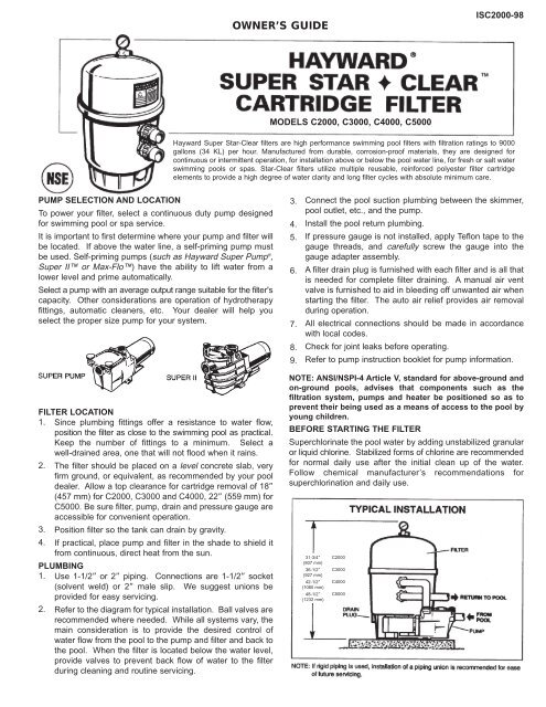
Hayward Super Star-Clear™ Cartridge Filter - Models C2000 ...
Hayward Super Star-Clear™ Cartridge Filter - Models C2000 ...
Hayward Super Star-Clear™ Cartridge Filter - Models C2000 ...

Create successful ePaper yourself
Turn your PDF publications into a flip-book with our unique Google optimized e-Paper software.
OWNER’S GUIDE<br />
IS<strong>C2000</strong>-98<br />
MODELS <strong>C2000</strong>, C3000, C4000, C5000<br />
<strong>Hayward</strong> <strong>Super</strong> <strong>Star</strong>-Clear filters are high performance swimming pool filters with filtration ratings to 9000<br />
gallons (34 KL) per hour. Manufactured from durable, corrosion-proof materials, they are designed for<br />
continuous or intermittent operation, for installation above or below the pool water line, for fresh or salt water<br />
swimming pools or spas. <strong>Star</strong>-Clear filters utilize multiple reusable, reinforced polyester filter cartridge<br />
elements to provide a high degree of water clarity and long filter cycles with absolute minimum care.<br />
PUMP SELECTION AND LOCATION<br />
To power your filter, select a continuous duty pump designed<br />
for swimming pool or spa service.<br />
It is important to first determine where your pump and filter will<br />
be located. If above the water line, a self-priming pump must<br />
be used. Self-priming pumps (such as <strong>Hayward</strong> <strong>Super</strong> Pump ® ,<br />
<strong>Super</strong> II or Max-Flo) have the ability to lift water from a<br />
lower level and prime automatically.<br />
Select a pump with an average output range suitable for the filter's<br />
capacity. Other considerations are operation of hydrotherapy<br />
fittings, automatic cleaners, etc. Your dealer will help you<br />
select the proper size pump for your system.<br />
3.<br />
4.<br />
5.<br />
6.<br />
7.<br />
8.<br />
9.<br />
Connect the pool suction plumbing between the skimmer,<br />
pool outlet, etc., and the pump.<br />
Install the pool return plumbing.<br />
If pressure gauge is not installed, apply Teflon tape to the<br />
gauge threads, and carefully screw the gauge into the<br />
gauge adapter assembly.<br />
A filter drain plug is furnished with each filter and is all that<br />
is needed for complete filter draining. A manual air vent<br />
valve is furnished to aid in bleeding off unwanted air when<br />
starting the filter. The auto air relief provides air removal<br />
during operation.<br />
All electrical connections should be made in accordance<br />
with local codes.<br />
Check for joint leaks before operating.<br />
Refer to pump instruction booklet for pump information.<br />
FILTER LOCATION<br />
1. Since plumbing fittings offer a resistance to water flow,<br />
position the filter as close to the swimming pool as practical.<br />
Keep the number of fittings to a minimum. Select a<br />
well-drained area, one that will not flood when it rains.<br />
2. The filter should be placed on a level concrete slab, very<br />
firm ground, or equivalent, as recommended by your pool<br />
dealer. Allow a top clearance for cartridge removal of 18”<br />
(457 mm) for <strong>C2000</strong>, C3000 and C4000, 22” (559 mm) for<br />
C5000. Be sure filter, pump, drain and pressure gauge are<br />
accessible for convenient operation.<br />
3. Position filter so the tank can drain by gravity.<br />
4. If practical, place pump and filter in the shade to shield it<br />
from continuous, direct heat from the sun.<br />
PLUMBING<br />
1. Use 1-1/2” or 2” piping. Connections are 1-1/2” socket<br />
(solvent weld) or 2” male slip. We suggest unions be<br />
provided for easy servicing.<br />
2. Refer to the diagram for typical installation. Ball valves are<br />
recommended where needed. While all systems vary, the<br />
main consideration is to provide the desired control of<br />
water flow from the pool to the pump and filter and back to<br />
the pool. When the filter is located below the water level,<br />
provide valves to prevent back flow of water to the filter<br />
during cleaning and routine servicing.<br />
NOTE: ANSI/NSPI-4 Article V, standard for above-ground and<br />
on-ground pools, advises that components such as the<br />
filtration system, pumps and heater be positioned so as to<br />
prevent their being used as a means of access to the pool by<br />
young children.<br />
BEFORE STARTING THE FILTER<br />
<strong>Super</strong>chlorinate the pool water by adding unstabilized granular<br />
or liquid chlorine. Stabilized forms of chlorine are recommended<br />
for normal daily use after the initial clean up of the water.<br />
Follow chemical manufacturer’s recommendations for<br />
superchlorination and daily use.<br />
31-3/4”<br />
(807 mm)<br />
36-1/2”<br />
(927 mm)<br />
42-1/2”<br />
(1080 mm)<br />
48-1/2”<br />
(1232 mm)<br />
<strong>C2000</strong><br />
C3000<br />
C4000<br />
C5000
IMPORTANT SAFETY INSTRUCTIONS.<br />
READ AND FOLLOW ALL INSTRUCTIONS.<br />
When installing and using this equipment, basic safety precautions<br />
must always be followed. This filter operates under high pressure.<br />
Failure to follow instructions may result in serious injury.<br />
•<br />
•<br />
•<br />
•<br />
REMOVE CLAMP TAPE. DO NOT LEAVE TAPE EXPOSED TO SUN.<br />
MAKE SURE CLAMP IS LOCATED AND CENTERED PROPERLY<br />
OVER THE FILTER FLANGE.<br />
BOTH SIDES OF THE CLAMP MUST BE TIGHTENED FIRMLY AND<br />
EVENLY UNTIL SPRING COILS TOUCH EACH OTHER (SEE<br />
ILLUSTRATION BELOW).<br />
FINAL SPACE BETWEEN BOTH CLAMP HALVES SHOULD BE<br />
EQUAL.<br />
CAUTION: All suction and discharge valves must be open when starting<br />
the system. Failure to do so could result in severe personal injury and/or<br />
property damage.<br />
The following clamp spring assembly, which includes a spring, two<br />
washers (small and large hole) and a sleeve nut, provides a<br />
visual means of ensuring that the clamp is tight.<br />
STARTING THE FILTER<br />
BE SURE CENTER CLAMP IS SECURE. Be sure filter drain plug<br />
is closed. Open Air Relief Valve at top of filter a few turns. Open<br />
suction and return valves (when used). Stand clear of filter and<br />
prime and start the pump, following the manufacturer’s<br />
instructions. Air trapped in the system will automatically vent to the<br />
pool and out the Air Relief Valve. Close Air Relief Valve when a<br />
steady stream of water emerges.<br />
FILTERING<br />
Filtration starts as soon as flow is steady through the filter. As the<br />
filter cartridge removes dirt from the pool water, the accumulated<br />
dirt causes a resistance to flow. As a result, the gauge pressure<br />
will rise and the flow will decrease. When the pressure rises 7-10<br />
psi (.49-.69 Bar) above the starting pressure, or when flow<br />
decreases below desired rate, clean or replace the filter cartridges.<br />
CLEAN/REPLACE CARTRIDGES<br />
Removing <strong>Cartridge</strong> Elements<br />
1. Shut off the pump.<br />
2. If filter is located below water level, close valves (or block off<br />
suction and discharge lines) to prevent backflow of water from<br />
pool.<br />
3. Unscrew and remove drain plug and allow water to drain from<br />
filter. Close drain plug. (Note: To assist draining process,<br />
open air vent a few turns.)<br />
4. Disassembly:<br />
5.<br />
a.<br />
b.<br />
Using a 9/16” wrench, alternately loosen both clamp<br />
sleeve nuts. Remove one clamp sleeve nut assembly<br />
(spring, two washers and sleeve nut) and carefully remove<br />
clamp.<br />
To remove <strong>Filter</strong> Head, tap it on the side to break seal at<br />
center of tank OR insert a blunt screwdriver into one of the<br />
notches located behind Connector Fittings, or 90˚ to the left<br />
of the Connector Fittings, and twist to lift filter head<br />
slightly. DO NOT grasp gauge assembly when removing<br />
filter head—breakage will result.<br />
To Remove <strong>Cartridge</strong>s:<br />
a. Lift off top closure plate.<br />
b. Remove cartridges from bottom collector manifold by using<br />
a slight rocking motion and lifting up.<br />
c. Clean cartridge. (see Cleaning <strong>Cartridge</strong>s)<br />
1.<br />
2.<br />
3.<br />
4.<br />
DEX2400J4<br />
Washer w/Small Hole<br />
DEX2400JS<br />
Spring<br />
DEX2400J3<br />
Washer w/Large Hole<br />
DEX2400JN<br />
Brass Sleeve Nut<br />
Reinstalling <strong>Cartridge</strong>s<br />
1. Flush and drain any dirt or debris from the bottom of the filter<br />
tank.<br />
2. Carefully replace cartridges over hubs on bottom manifold.<br />
Place top closure plate securely into top of cartridges.<br />
3. Clean and lightly lubricate Tank O-ring and carefully place<br />
over <strong>Filter</strong> Body lip.<br />
4. Clean <strong>Filter</strong> Head flange sealing surface, and place over Tank<br />
O-ring, pressing down firmly and evenly to seat the <strong>Filter</strong><br />
Head in place.<br />
5. Replace Clamp Assembly. Make sure clamp is located and<br />
centered properly over the filter flange. If Clamp is tight, tap<br />
Clamp with rubber mallet or block of wood to help seat it.<br />
Insert threaded stud through retainer and secure with Clamp<br />
Spring Assembly (be sure to position small and large hole<br />
washers properly—see illustration in IMPORTANT SAFETY<br />
INSTRUCTIONS).<br />
In some cases it may be necessary to use the two-part filter<br />
clamp to assist in assembling the filter cover to the filter base.<br />
With one nut, spring and washer assembly already removed,<br />
loosen the remaining clamp nut to maximize clamp opening. If<br />
Clamp is tight, tap Clamp with rubber mallet or block of wood<br />
to help seat it as you are tightening nuts. If the two (2) clamp<br />
springs (DE2400JS) are temporarily removed in order to fully<br />
extend the clamp bolts, the clamp springs and washers MUST<br />
be reassembled as shown in the CLAMP SPRING ASSEMBLY<br />
diagram in IMPORTANT SAFETY INSTRUCTIONS.<br />
Tighten sleeve nuts alternately to secure Clamp firmly and<br />
evenly to form a good seal (be sure spring coils touch each<br />
other and final space between Clamp halves is even—see<br />
illustration in IMPORTANT SAFETY INSTRUCTIONS).<br />
6. Install Drain Plug, open pool suction and return valves and<br />
proceed as in STARTING THE FILTER.<br />
Cleaning <strong>Cartridge</strong>s<br />
The cartridge filter element can be cleaned by pressure washing<br />
inside and out with a garden hose. (The cartridge is easier to<br />
clean when dry.) After hosing the cartridge, for best results, allow<br />
cartridge to dry and carefully brush pleated surface areas to<br />
remove fine particles.<br />
Algae, suntan oil and body oils can form a coating on the cartridge<br />
pleats which may not be thoroughly removed by hosing. To remove<br />
such materials, soak the cartridge in a solution of filter element<br />
cleaner (various brands are available at pool dealer). Follow<br />
manufacturer’s directions for use and allow an hour for soaking.<br />
Hose thoroughly before reinstalling the filter.<br />
If calcium or mineral deposits are excessive, the cartridge may be<br />
restored to “like new” condition by soaking in muriatic acid. Use<br />
commercially available 20% muriatic acid added to water in 1 to 1<br />
ratio. Use a plastic container and take extreme care when handling<br />
cleaning agents as they can be harmful to eyes, skin and clothing.<br />
After cleaning, flush with water.<br />
A spare cartridge filter element is an excellent investment. It<br />
provides convenience and ensures that your filter will always be<br />
ready to operate at peak efficiency.<br />
<strong>Hayward</strong> cartridges are specifically designed and engineered for<br />
use in <strong>Star</strong>-Clear filters. For best results, use only genuine<br />
<strong>Hayward</strong> <strong>Star</strong>-Clear cartridges in your filter. Order Model No.<br />
CX470XRE, CX570XRE, CX870XRE or CX1260RE from your<br />
dealer. The <strong>Hayward</strong> name is your guarantee of quality.<br />
VACUUMING<br />
Vacuuming can be performed directly into the filter whenever<br />
needed. Clean cartridges after vacuuming, if required.
WINTERIZING<br />
In areas where sub-freezing temperatures can be expected,<br />
the filter should be drained and/or removed from its operating<br />
location and stored indoors. Remove and clean cartridges.<br />
Reinstall cartridges in filter tank.<br />
SERVICE AND REPAIRS<br />
Consult your local authorized <strong>Hayward</strong> dealer or service<br />
center. No returns may be made directly to the factory without<br />
the expressed written authorization of <strong>Hayward</strong> Pool Products,<br />
Inc.<br />
ALGAE CONTROL<br />
Algae is a form of plant life which can vary in size from a few<br />
thousandths of an inch to the size of a small tree. Of the many<br />
forms of algae, those most frequently found in swimming pool<br />
water are microscopic in size and green in color.<br />
Algae readily grows in sunlight and can, under favorable<br />
conditions quickly overgrow a swimming pool turning it<br />
completely green in just a few hours. On the other hand,<br />
swimming pool water can be unfavorable to algae growth<br />
simply by maintaining a chlorine level of at least 1.0 ppm in the<br />
water at all times. The chlorine level should be checked at least<br />
once a day using a suitable test kit.<br />
If an algae condition develops and the pool water “blooms”<br />
green, superchlorination of the pool will be necessary to clear<br />
it. Add unstabilized granular chlorine, or liquid chlorine. Follow<br />
chemical manufacturer’s recommendation for superchlorination.<br />
The algae will quickly become inactive and can then be<br />
removed by the filter. Live algae, on the other hand, multiplies<br />
so fast that the filter cannot keep up with its growth rate.<br />
When correctly used, commercial algaecides are effective<br />
against algae, though algaecides should be used in<br />
conjunction with, and not as a substitute for, regular<br />
chlorination or superchlorination.<br />
Maintaining a chlorine level of at least 1.0 ppm in the pool water<br />
at all times is the most effective way to prevent algae growth in<br />
swimming pools.<br />
PLEASE REALIZE . . .<br />
Pure, clear swimming pool water is a combination of two<br />
factors—adequate filtration and proper water chemistry<br />
balance. One without the other will not give the clean, clear<br />
water you desire.<br />
Your filter system is designed for continuous operation.<br />
However, this is not necessary for most swimming pools. You<br />
can determine your filter operation schedule based on your<br />
pool size and usage. Be sure to operate your filtration system<br />
long enough each day to obtain at least one complete turnover<br />
of your pool water.<br />
To properly sanitize your pool, maintain a free chlorine level of<br />
1 to 3 ppm and a pH range of 7.2 and 7.6. Insufficient chlorine<br />
or an out of balance pH level will permit algae and bacteria to<br />
grow in your pool and make it difficult for your filter to properly<br />
clean the pool water.<br />
POOL CHEMISTRY GUIDELINES<br />
pH<br />
SUGGESTED POOL CHEMISTRY LEVELS<br />
7.2 to 7.6<br />
ACTION REQUIRED TO CORRECT POOL CHEMISTRY<br />
TO RAISE<br />
TO LOWER<br />
Add Soda Ash<br />
Add Muriatic Acid or Sodium Bisulphate<br />
TOTAL ALKALINITY<br />
100 to 130 ppm<br />
Add Sodium Bicarbonate<br />
Add Muriatic Acid<br />
CHLORINE (UNSTABILIZED)<br />
0.3 to 1.0 ppm<br />
Add Chlorine Chemical<br />
No action—chlorine will naturally dissipate<br />
CHLORINE (STABILIZED)<br />
1.0 to 3.0 ppm<br />
Add Chlorine Chemical<br />
No action—chlorine will naturally dissipate<br />
CHLORINE STABILIZER<br />
(Cyanuric Acid)<br />
40 to 70 ppm<br />
Add Stabilizer<br />
Dilution—partially drain & refill pool with water<br />
that has not been treated with Cyanuric Acid.<br />
Rev: 11/98<br />
©1998 <strong>Hayward</strong>
SUPER STAR-CLEAR SPECIFICATIONS<br />
MODEL<br />
NO.<br />
<strong>C2000</strong><br />
C3000<br />
C4000<br />
C5000<br />
EFFECTIVE<br />
FILTRATION<br />
AREA<br />
FT 2 M 2<br />
200 19<br />
300 28<br />
400 37<br />
500 47<br />
DESIGN FLOW RATE<br />
RESIDENTIAL PUBLIC<br />
GPM<br />
75<br />
112<br />
150<br />
150<br />
LPM<br />
284<br />
424<br />
568<br />
568<br />
GPM<br />
75<br />
112<br />
150<br />
150<br />
LPM<br />
284<br />
424<br />
568<br />
568<br />
PRESSURE LOSS AT<br />
DESIGN FLOW RATE<br />
RESIDENTIAL PUBLIC<br />
PSI<br />
2.1<br />
5.1<br />
6.8<br />
6.8<br />
BAR<br />
0.15<br />
0.36<br />
0.47<br />
0.47<br />
PSI<br />
2.1<br />
5.1<br />
6.8<br />
6.8<br />
BAR<br />
0.15<br />
0.36<br />
0.47<br />
0.47<br />
MAXIMUM<br />
WORKING<br />
PRESSURE<br />
PSI BAR<br />
50 3.45<br />
50 3.45<br />
50 3.45<br />
50 3.45<br />
REQUIRED CLEARANCE<br />
SIDE ABOVE<br />
IN<br />
18<br />
18<br />
18<br />
18<br />
CM<br />
46<br />
46<br />
46<br />
46<br />
IN<br />
18<br />
18<br />
18<br />
22<br />
CM<br />
46<br />
46<br />
46<br />
56<br />
PARTS<br />
<strong>Super</strong> <strong>Star</strong>-Clear<br />
<strong>Models</strong> <strong>C2000</strong>, C3000, C4000, C5000<br />
REF.<br />
NO.<br />
1<br />
2<br />
---<br />
3<br />
4a<br />
4b<br />
4c<br />
4d<br />
5<br />
6a<br />
6b<br />
6c<br />
6d<br />
7<br />
8a<br />
8b<br />
8c<br />
9<br />
10<br />
11<br />
12a<br />
12b<br />
12c<br />
12d<br />
13<br />
14a<br />
14b<br />
14c<br />
14d<br />
15<br />
16<br />
17<br />
18<br />
19<br />
20<br />
21<br />
22<br />
MODEL<br />
NUMBER<br />
ECX270861<br />
DEX2400S<br />
DEX2400Z3A<br />
SX200Z5<br />
DEX2400BT<br />
DEX3600BT<br />
DEX4800BT<br />
DEX6000BT<br />
DEX2400J<br />
DEX2400J4<br />
DEX2400JS<br />
DEX2400J3<br />
DEX2400JN<br />
DEX2400K<br />
CX2000DA<br />
CX3000DA<br />
CX5000DA<br />
CX3000F1B<br />
CX3000FB<br />
DEX360M<br />
CX800Z4<br />
CX3000Z3<br />
CX4000Z3<br />
CX5000Z3<br />
CX3000J<br />
CX470XRE<br />
CX570XRE<br />
CX870XRE<br />
CX1260RE<br />
CX3000C<br />
DEX2400A1T<br />
SPX1022C<br />
SX360Z1<br />
DEX360FB<br />
SX200Z4<br />
SX240F<br />
SX200R<br />
DESCRIPTION<br />
Pressure Gauge<br />
Relief Valve/Gauge Adapter Assy.<br />
O-Ring for Relief Valve Stem (Set 3)<br />
Relief Valve Assembly O-Ring<br />
<strong>Filter</strong> Head (<strong>C2000</strong>)<br />
<strong>Filter</strong> Head (C3000)<br />
<strong>Filter</strong> head (C4000)<br />
<strong>Filter</strong> Head (C5000)<br />
Clamp Assembly<br />
Washer w/Small Hole<br />
Spring<br />
Washer w/Large Hole<br />
Brass Sleeve Nut<br />
<strong>Filter</strong> Tank O-Ring<br />
Top Closure Plate (<strong>C2000</strong>)<br />
Top Closure Plate (C3000, C4000)<br />
Top Closure Plate (C5000)<br />
Inlet Elbow<br />
Outlet Elbow<br />
O-Ring<br />
Air Relief Tube<br />
Air Relief Tube<br />
Air Relief Tube<br />
Air Relief Tube<br />
Air Tube Screen<br />
<strong>Cartridge</strong> Element (<strong>C2000</strong>)<br />
<strong>Cartridge</strong> Element (C3000)<br />
<strong>Cartridge</strong> Element (C4000)<br />
<strong>Cartridge</strong> Element (C5000)<br />
Bottom Collector Manifold<br />
<strong>Filter</strong> Body<br />
1-1/2” Drain Plug w/O-Ring<br />
O-Ring<br />
Bulkhead Fitting<br />
O-Ring<br />
1-1/2” SKT. x 2” SLIP Connector<br />
Locknut<br />
NO.<br />
REQ’D.<br />
1<br />
1<br />
1<br />
1<br />
1<br />
1<br />
1<br />
1<br />
1<br />
2<br />
2<br />
2<br />
2<br />
1<br />
1<br />
1<br />
1<br />
1<br />
1<br />
1<br />
1<br />
1<br />
1<br />
1<br />
1<br />
4<br />
4<br />
4<br />
4<br />
1<br />
1<br />
1<br />
2<br />
2<br />
2<br />
2<br />
2
ISC3000INS-99<br />
IMPORTANT: For winterizing, in addition to removing the drain plug at the bottom of<br />
the filter, please also make sure to remove the two screws at the bottom of the manifold<br />
so that the filter and the manifold can be drained thoroughly.<br />
ISC3000INS-99<br />
IMPORTANT: For winterizing, in addition to removing the drain plug at the bottom of<br />
the filter, please also make sure to remove the two screws at the bottom of the manifold<br />
so that the filter and the manifold can be drained thoroughly.