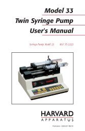
Model 44 Syringe Pump Series Manual - Harvard Apparatus
Model 44 Syringe Pump Series Manual - Harvard Apparatus
Model 44 Syringe Pump Series Manual - Harvard Apparatus

You also want an ePaper? Increase the reach of your titles
YUMPU automatically turns print PDFs into web optimized ePapers that Google loves.
<strong>Model</strong> ‘<strong>44</strong>’<br />
<strong>Syringe</strong> <strong>Pump</strong> <strong>Series</strong><br />
User’s <strong>Manual</strong><br />
<strong>Model</strong> ‘<strong>44</strong>’ Programmable 55-11<strong>44</strong>
1<br />
Table of Contents<br />
H a r v a r d A p p a r a t u s P e r i s t a l t i c P u m p M o d e l ‘ 6 6 / 7 7 ’<br />
SUBJECT<br />
PAGE NO.<br />
Table of Contents..............................................................................................1<br />
General Information – Warranty and Repairs ................................................2-3<br />
Technical Specifications ................................................................................4-5<br />
Features ............................................................................................................6<br />
Theory of Operation and Initial Setup..............................................................7<br />
Loading <strong>Syringe</strong>s ..............................................................................................8<br />
User Interface....................................................................................................9<br />
Description of Keys ..................................................................................10-11<br />
Entering Data ............................................................................................11-12<br />
Operation ..................................................................................................13-15<br />
Diameter ................................................................................................13<br />
Infuse/Refill Rates..............................................................................13-14<br />
Auto Fill..................................................................................................14<br />
Selecting the Run Mode ....................................................................14-15<br />
Running the <strong>Pump</strong> ................................................................................15<br />
Program Mode ..........................................................................................16-17<br />
Description of Sequence Operations..........................................................18-20<br />
External Control and Interfaces ................................................................21-22<br />
RS-232 Devices ......................................................................................21<br />
TTL Devices ..........................................................................................22<br />
Programming Tutorial................................................................................23-31<br />
<strong>Pump</strong> Chain Commands ................................................................................32<br />
Command Formats & their Meaning..............................................................33<br />
<strong>Pump</strong> Commands & Responses ................................................................34-40<br />
Appendcies ................................................................................................41-54<br />
A Table of <strong>Syringe</strong> Diameters ............................................................41<br />
B Nominal Minimum and Maximum Flow Rates ..............................42<br />
C Pressure and Force Specifications ....................................................43<br />
D <strong>Pump</strong> Chain Command Summary ............................................<strong>44</strong>-45<br />
E RS-232 Specifications ................................................................46-47<br />
F TTL Connector Specifications ........................................................48<br />
G Maintenance ..................................................................................49<br />
H Troubleshooting ..............................................................................50<br />
I Accessories ......................................................................................51<br />
J Custom Applications / <strong>Pump</strong> ‘<strong>44</strong>’ Variations ..................................52<br />
K <strong>Pump</strong> ‘<strong>44</strong>’ Auto Fill Valves ........................................................53-54
2<br />
General Information<br />
H a r v a r d A p p a r a t u s P e r i s t a l t i c P u m p M o d e l ‘ 6 6 / 7 7 ’<br />
Serial Numbers<br />
All inquires concerning our product should refer to the serial number of the unit.<br />
Serial numbers are located on the rear of the chassis.<br />
Calibrations<br />
All electrical apparatus is calibrated at rated voltage and frequency. While the flow<br />
will stay calibrated, the peak will vary.<br />
Warranty<br />
<strong>Harvard</strong> <strong>Apparatus</strong> warranties this instrument for a period of one year from date of<br />
purchase. At its option, <strong>Harvard</strong> <strong>Apparatus</strong> will repair or replace the unit if it is<br />
found to be defective as to workmanship or material.<br />
This warranty does not extend to damage resulting from misuse, neglect or abuse,<br />
normal wear and tear, or accident.<br />
This warranty extends only to the original customer purchaser.<br />
IN NO EVENT SHALL HARVARD APPARATUS BE LIABLE FOR INCI-<br />
DENTAL OR CONSEQUENTIAL DAMAGES. Some states do not allow exclusion<br />
or limitation of incidental or consequential damages so the above limitation or<br />
exclusion may not apply to you. THERE ARE NO IMPLIED WARRANTIES OF<br />
MERCHANTABILITY, OR FITNESS FOR A PARTICULAR USE, OR OF<br />
ANY OTHER NATURE. Some states do not allow this limitation on an implied<br />
warranty, so the above limitation may not apply to you.<br />
If a defect arises within the one-year warranty period, promptly contact <strong>Harvard</strong><br />
<strong>Apparatus</strong>, Inc. 84 October Hill Road, Building 7, Holliston, Massachusetts<br />
01746-1371 using our toll free number 1-800-272-2775. Goods will not be<br />
accepted for return unless an RMA (returned materials authorization) number has<br />
been issued by our customer service department. The customer is responsible for<br />
shipping charges. Please allow a reasonable period of time for completion of repairs,<br />
replacement and return. If the unit is replaced, the replacement unit is covered only<br />
for the remainder of the original warranty period dating from the purchase of the<br />
original device.<br />
This warranty gives you specific rights, and you may also have other rights which<br />
vary from state to state.
3<br />
General Information (Contd)<br />
H a r v a r d A p p a r a t u s P e r i s t a l t i c P u m p M o d e l ‘ 6 6 / 7 7 ’<br />
Repair Facilities and Parts<br />
<strong>Harvard</strong> <strong>Apparatus</strong> stocks replacement and repair parts. When ordering, please<br />
describe parts as completely as possible, preferably using our part numbers. If practical,<br />
enclose a sample or drawing. We offer a complete reconditioning service.<br />
CAUTION !<br />
This pump is not registered with the FDA and is not for clinical use on human<br />
patients.
4<br />
Specifications<br />
H a r v a r d A p p a r a t u s P e r i s t a l t i c P u m p M o d e l ‘ 6 6 / 7 7 ’<br />
<strong>Pump</strong> ‘<strong>44</strong>’ Specifications<br />
Type<br />
Single <strong>Syringe</strong> Infusion/Withdrawal<br />
Size<br />
257 x 289 x 152 mm (10.1 x 11.4 x 6 in)<br />
Weight<br />
7.25 kg (16 lb)<br />
Power<br />
115/230 VAC, 50/60 Hz via selector switch, 65 W<br />
Fuse<br />
3AG 1/2 AMP 250 V SLO-BLO<br />
Leakage to Ground<br />
Typically < 10 µ A<br />
Ground Resistance Typically < 0.05<br />
Voltage Operating Range 95 to 130 VAC, 220 to 260 VAC<br />
Drive Motor<br />
1.8° stepper<br />
Motor Drive Circuitry Microprocessor controlled from 1/2 to 1/32<br />
microstepping<br />
Timing Belt Drive 2:1<br />
Lead Screw Pitch<br />
24 threads/in<br />
Motor Steps per<br />
One Revolution of Lead Screw From 800 to 12,800 dependent on rate<br />
Step Rate:<br />
Minimum<br />
27.3 sec/step<br />
Maximum<br />
416.7 µ sec/step<br />
Minimum Pusher Advance/Step 0.082 µ m<br />
Pusher Travel Rate:<br />
Minimum<br />
0.18 µ m/min<br />
Maximum<br />
190.676 mm/min<br />
Dynamic Speed Range 1,059,311 to 1<br />
Maximum Force<br />
193 lb<br />
Maximum Pressure<br />
1500 psi with an 8 ml stainless steel syringe<br />
Accuracy ±1%<br />
Reproducibility ±0.1%
5<br />
Specifications (Contd)<br />
H a r v a r d A p p a r a t u s P e r i s t a l t i c P u m p M o d e l ‘ 6 6 / 7 7 ’<br />
<strong>Pump</strong> ‘<strong>44</strong>’ Specifications<br />
Calibration<br />
<strong>Syringe</strong> Size:<br />
Minimum<br />
Maximum<br />
Flow Rate Range:<br />
Minimum<br />
Maximum<br />
Display<br />
RS-232 Interface<br />
Non-Volatile Memory<br />
Enter syringe dia. from table, any size, any<br />
make up to 50 mm dia.<br />
0.5 µ l<br />
140 ml<br />
0.0001 µ l/hr (0.5 µ l syringe)<br />
220.82 ml/min (140 ml syringe)<br />
20 character alphanumeric vacuum<br />
fluorescent; 5 LED indicators<br />
Multiplexed dual bidirectional ports<br />
Storage of all settings
Features<br />
6<br />
H a r v a r d A p p a r a t u s P e r i s t a l t i c P u m p M o d e l ‘ 6 6 / 7 7 ’<br />
Pressure and Speed<br />
<strong>Pump</strong> ‘<strong>44</strong>’ can deliver up to 220.82 ml/mm with a 140 ml syringe and is capable of<br />
pressures up to 1500 PSI with an 8 ml stainless steel syringe. (See Appendix C).<br />
Built-in <strong>Syringe</strong> Table and Custom <strong>Syringe</strong>s<br />
If a non-standard syringe is to be used, enter the inside diameter in millimeters.<br />
If a standard syringe is to be used, select your syringe using the pump's built-in syringe<br />
table. <strong>Syringe</strong>s are arranged according to manufacturer and material, and then according<br />
to size. The pump will look up and use the diameter for the syringe you select. (See<br />
Appendix A for standard syringes).<br />
Infusion and Refill Rates<br />
Specify independent rates for infusing and refilling. This allows a slow infusion rate then<br />
a fast refill.<br />
Auto Fill<br />
Auto Fill automatically activates an externally attached solenoid and refills the syringe<br />
when it is empty. This permits infusions to be virtually independent of syringe capacity.<br />
Modes of Operation<br />
<strong>Pump</strong> – Runs continuously, infuse or refill, until stopped<br />
Volume – Runs until a specified volume has been pumped or refilled<br />
Program – <strong>Pump</strong> operates according to a specified sequence of instructions<br />
(Note: All modes interact with Auto Fill feature)<br />
External Connections<br />
TTL – Allows pump operations to be synchronized with external devices or by<br />
a person at a distance from the pump. Direction of pump travel can be<br />
set via a TTL pin. Also, a TTL pin is used to control an external valve<br />
for refilling. Additional TTL pins are available for general use.<br />
RS-232 – Multiple pumps can be “daisy chained” together and remotely controlled<br />
from a computer or any device communicating via RS-232.<br />
A scale can be attached, enabling the pump to infuse by weight instead of by volume.<br />
A printer can be attached to record final volumes or weights whenever the pump stops. In<br />
addition the program entered for the program mode can be listed on an attached printer.<br />
Nonvolatile Memory<br />
All operational data entered into the pump from the keypad or from a computer will be<br />
stored, including the program. On power up, the display will blink until the pump<br />
receives its first command and all settings from when it was powered down will be<br />
recalled. If in an unlikely event a failure to properly recall the data occurs, the settings<br />
will be reset and the display will read: SETTINGS RESET.<br />
Stall Detection<br />
An optical detector is used to verify expected movement of the motor. If the motor is<br />
prevented from turning due to jamming or kinking of the tubing, the pump will stop and<br />
the display will read: PUMP STALLED.
7<br />
Theory of Operation<br />
H a r v a r d A p p a r a t u s P e r i s t a l t i c P u m p M o d e l ‘ 6 6 / 7 7 ’<br />
<strong>Pump</strong> ‘<strong>44</strong>’ employs a microcontroller which controls a small step angle stepping<br />
motor that drives a lead screw and half nut. Microstepping techniques are<br />
employed to further reduce the step angle, making flow pulsation negligible. A key<br />
pad is used for entry of operating data to the pump. Data can also be entered via<br />
RS-232. The microcontroller calculates the cross-sectional area of the syringe<br />
selected and calibrates the flow rate and volume accumulation. The numerous features<br />
of the <strong>Pump</strong> ‘<strong>44</strong>’ result from the use of microcontroller technology.<br />
Initial Set-Up<br />
1. Read the manual.<br />
2. Locate the voltage selector switch on the rear panel of the pump and set it to<br />
the voltage being used. If other than 110 V, 60 Hz is being used, the plug<br />
must be cut off and an appropriate plug installed, observing the polarity of<br />
the international line cord used:<br />
Brown – live<br />
Blue – neutral<br />
Green – ground<br />
3. Turn on main power switch located directly above the line cord on the rear<br />
panel. The display will now illuminate indicating that the power connections<br />
are correct. The flashing display indicates that power has just been applied.<br />
4. Load syringe, see next page.
8<br />
Loading <strong>Syringe</strong>s<br />
H a r v a r d A p p a r a t u s P e r i s t a l t i c P u m p M o d e l ‘ 6 6 / 7 7 ’<br />
(Diagram 1)<br />
◆<br />
◆<br />
◆<br />
The syringe holder and pusher block are fitted with movable retaining brackets<br />
which hold firmly the syringe barrel and plunger when refilling. When<br />
loading the syringe into the pump it is necessary to adjust these brackets. The<br />
pusher block is fitted with a mechanism to release the drive nut from the leadscrew<br />
so that the block can be moved freely to facilitate loading the syringe.<br />
Loosen the screws on the syringe block and pusher block to free the retaining<br />
brackets (2 & 3, Diag. 1).<br />
To free the pusher block from the leadscrew, turn the knob on the front of the<br />
block (1) until the pin in the knob slips into the hole in the block.<br />
◆ The syringe clamp locking screw on the right side of the syringe block (4)<br />
should be loosened and the clamp rotated to the side.<br />
◆<br />
◆<br />
◆<br />
1 2 3 4<br />
Place the syringe barrel on the syringe holder block and move the pusher block<br />
to accommodate the plunger.<br />
Make sure the syringe barrel flange and the plunger flange are held by the<br />
retaining clamps. Press the retaining brackets firmly against the flanges and<br />
tighten the retaining screws.<br />
Rotate the syringe clamp and press down firmly on the syringe barrel. Secure<br />
in place by tightening the locking screw (4).
9<br />
User Interface<br />
H a r v a r d A p p a r a t u s P e r i s t a l t i c P u m p M o d e l ‘ 6 6 / 7 7 ’<br />
The user interface consists of a display area and a keypad. The display consists of a<br />
20 character alphanumeric vacuum fluorescent display and 5 LED indicators. The<br />
display will show one of three types of messages: default display, setting display, or an<br />
informational message.<br />
The default display is divided into three sections. The first consists of the delivered<br />
volume, or time interval remaining in an operation, expressed with 5 digits plus a<br />
decimal point. Next is the units of the previous number expressed as “ml” for milliliters,<br />
“g” for grams, if a scale is attached, or “time” for a time interval. Third is<br />
the pumping direction, either “INFUSE” or “REFILL”, or the current operating<br />
state of the pump. A diamond symbol in the last character of the display indicates<br />
pump chain communication has been received.<br />
Setting displays are used to facilitate entering control information and data into the<br />
pump. Data entry will be discussed in detail.<br />
Informational messages occur at various times to indicate such items as a data setting<br />
out of range, or a detected problem, such as the pump stalling. Pressing any<br />
key clears the message from the display.<br />
The LED indicators have the following meanings when lit:<br />
<strong>Pump</strong> Mode – Indicates <strong>Pump</strong> run mode<br />
Vol. Mode – Indicates Target Volume run mode<br />
Prog. Mode – Indicates Program run mode<br />
Auto Fill – Indicates Auto Fill feature is on<br />
Run – Indicates motor is running
10<br />
Description of Keys<br />
H a r v a r d A p p a r a t u s P e r i s t a l t i c P u m p M o d e l ‘ 6 6 / 7 7 ’<br />
The keypad consists of 23 keys used for entering control information and data into<br />
the pump. These keys are grouped into 3 sections (see Diagram 2): set keys, toggle<br />
keys, and data entry keys.<br />
––––––––––––––––––––––––––––––––––––––––<br />
(Diagram 2)<br />
Set Keys<br />
HARVARD APPARATUS<br />
Set<br />
Diameter<br />
Run<br />
Stop<br />
Infuse<br />
Rate<br />
Refill Rate<br />
Infuse<br />
Target<br />
Volume<br />
Auto Fill<br />
Refill<br />
Toggle<br />
RS -232<br />
Program<br />
Select Mode<br />
1 2 3<br />
4 5 6<br />
7 8 9<br />
enter 0<br />
Data Entry<br />
Set Keys<br />
SET – Allows modification of a data item in this group of keys. To<br />
modify a data item, press the relevant key after pressing the SET key.<br />
INFUSE RATE – Displays/sets current infuse rate. Scrolls through<br />
rate units when setting. Displays current programmed rate while running<br />
in program mode.<br />
REFILL RATE – Displays/sets current refill rate. Scrolls through rate<br />
units when setting.<br />
DIAMETER – Displays/sets current syringe diameter. When held<br />
down during setting, enters built-in syringe table.<br />
TARGET VOLUME – Displays/sets current volume mode target volume.<br />
RS-232 – Displays/sets current RS-232 device(s) attached.<br />
AUTO FILL – Turns Auto Fill feature setting on/off. Also,<br />
displays/sets syringe refill volume.<br />
PROGRAM – Displays current sequence number of program. Held<br />
down, with a printer attached and the pump stopped, prints a program<br />
listing.
11<br />
Description of Keys (Contd)<br />
H a r v a r d A p p a r a t u s P e r i s t a l t i c P u m p M o d e l ‘ 6 6 / 7 7 ’<br />
Toggle Keys<br />
SELECT MODE – Toggles between PUMP/DISPENSE/PROGRAM<br />
run modes with each press of the key. LED indicators display current<br />
mode. <strong>Pump</strong> must be stopped.<br />
INFUSE/REFILL – Changes direction of syringe travel for <strong>Pump</strong> and<br />
Volume modes. <strong>Pump</strong> must be stopped or in pump mode.<br />
RUN/STOP – Starts/stops–interrupts pump.<br />
Data Entry Keys<br />
1, 2, 3, 4, 5, 6, 7, 8, 9, 0, – Used to facilitate the entering<br />
of numeric data values.<br />
ENTER – Stores displayed data value when setting a data item.<br />
Entering Data<br />
Set Keys<br />
The yellow keys in this group are used to modify or review settings of the pumps<br />
control data. To review the current setting of a control data item, simply hold down<br />
the relevant key and the data setting will appear in the display. In the case of the<br />
PROGRAM key, the data will be sent to the printer if one is attached.<br />
To modify a data setting, first press then release the green SET key. The display<br />
should then read “SET WHAT?”. Press the key in the SET key group whose data<br />
is to be modified. The display will display the current setting. Data is entered into<br />
the pump by either entering a numerical value or by scrolling through a menu of<br />
choices. Always press ENTER to terminate each data request by the pump.<br />
If you are to enter a numerical value, the far left of the display will show “ENTER”<br />
followed by the units of the number to be entered. Using the numerical keys on<br />
the right side of the keypad (see diagram) enter the new data value. Up to five digit<br />
numbers are accepted, including up to four decimal places.<br />
Entering more than five digits will clear the previous five digits in the display. Press<br />
the green ENTER key when the desired data value is displayed.<br />
If the far left of the display does not show “ENTER”, then a menu of choices is<br />
being displayed. Pressing the relevant key, according to the choices being displayed,<br />
selects successive menu entries. When the desired selection is displayed, press the<br />
green ENTER key.
12<br />
Entering Data (Contd)<br />
H a r v a r d A p p a r a t u s P e r i s t a l t i c P u m p M o d e l ‘ 6 6 / 7 7 ’<br />
If the data value entered is outside the pump’s operating parameters, the display<br />
will read “OUT OF RANGE”. Pressing any key will restore the display with the<br />
original data value. Enter another data value within the pump’s parameters or just<br />
press ENTER to reuse the original data value.<br />
The data value entered can be reviewed as described above. Note: Certain data<br />
items have multiple settings. For these, after the ENTER key is pressed, the display<br />
will prompt you for the additional information. Various rules apply to when,<br />
what and how data can be set at various times. See the relevant section for further<br />
details.<br />
Toggle Keys<br />
The keys in this group, when permitted, select successive states of the keys’ function<br />
when pressed.
13<br />
Operation<br />
H a r v a r d A p p a r a t u s P e r i s t a l t i c P u m p M o d e l ‘ 6 6 / 7 7 ’<br />
Because of the wide range of functions that the <strong>Pump</strong> ‘<strong>44</strong>’ is capable of performing,<br />
certain information about your application must be entered into the pump. At<br />
minimum, the pump needs to know the diameter of your syringe, the infusion rate<br />
and direction of travel. This is the only information needed to operate the pump in<br />
the <strong>Pump</strong> Mode. If not specified, the Refill Rate will default to the Infuse Rate.<br />
The pump will need additional information to utilize its more advanced features.<br />
See the section on User interface for general information on data entry.<br />
Diameter<br />
If the inside diameter of the syringe being used is known, enter the value in millimeters.<br />
Otherwise, access the built-in syringe table and select your syringe. After<br />
a new diameter is entered, directly or via the built-in table, the Infuse Rate and<br />
Refill Rate are set to 0 and the Auto Fill feature is turned off. This is done for reasons<br />
of safety. The maximum diameter is 50 mm.<br />
To access the built-in syringe table, after pressing the SET key then the DIAME-<br />
TER key, hold down the DIAMETER key for about one second. Using the DIAM-<br />
ETER key, find the manufacturer and material, if applicable, of your syringe. Press<br />
the ENTER key to enter your selection. Now, using the DIAMETER key again,<br />
find the size of your syringe, in CC or UL, as indicated on the display. Pressing the<br />
ENTER key will select the size of the syringe and look up and store the diameter.<br />
The diameter will be displayed until the ENTER key is released. Thereafter, pressing<br />
the DIAMETER key will display the selected diameter. In addition, the syringe<br />
size selected becomes the default Refill Volume when the Auto Fill feature is turned<br />
on. See Appendix A for a listing of the built-in syringe table and their respective<br />
diameters.<br />
Infuse Rate<br />
The Infuse Rate is the rate of pumping while infusing in the <strong>Pump</strong> or Volume<br />
modes. Also, the Infuse Rate is used as a starting rate for the program mode if one<br />
is not specified in the program, regardless of pumping direction.<br />
When entering the Infuse Rate, the INFUSE RATE key is used to scroll through<br />
the allowable units of rate. The allowable units are: ml/mn, ml/hr, µl/mn, µl/hr.<br />
While running in the <strong>Pump</strong> or Volume modes, the Infuse Rate can be changed. If<br />
the new rate is valid, it will take effect when the ENTER key is pressed.<br />
The minimum and maximum rates permitted vary depending on the diameter of<br />
the syringe. If an “OUT OF RANGE” message is displayed when entering a rate,<br />
try using a different syringe for your application.
14<br />
Operation (Contd)<br />
H a r v a r d A p p a r a t u s P e r i s t a l t i c P u m p M o d e l ‘ 6 6 / 7 7 ’<br />
Refill Rate<br />
The Refill Rate is the rate of pumping while refilling in the <strong>Pump</strong> or Volume Modes<br />
or during Auto Fill. If the Refill Rate hasn’t been set (rate is 0), the Refill Rate will<br />
default to the Infuse Rate.<br />
When entering the Refill Rate, the REFILL RATE key is used to scroll through the<br />
allowable units of rate. The allowable units are: ml/mn, ml/hr, µl/mn, µl/hr.<br />
While running in the <strong>Pump</strong> or Volume modes, the Refill Rate can be changed. If<br />
the new rate is valid, it will take effect when the ENTER key is pressed.<br />
The minimum and maximum rates permitted vary depending on the diameter of<br />
the syringe. If an “OUT OF RANGE” message is displayed when entering a rate,<br />
try using a different syringe.<br />
Auto Fill<br />
While setting, use the AUTO FILL key to toggle between Auto Fill “on” and “off”.<br />
If Auto Fill is set to “on”, the pump will next request the volume of the syringe in<br />
milliliters. The volume of the syringe is used as the refill volume of the syringe.<br />
When set to “on”, the syringe is assumed to be empty. Auto Fill continuously monitors<br />
the volume of the syringe according to the volume pumped. When the pump<br />
determines that the syringe is empty, the operation in progress is suspended and<br />
Auto Fill is activated. The pumping direction is then reversed and the pump runs<br />
at the refill rate. During the Auto Fill operation, the display will indicate the volume<br />
in the syringe.<br />
When the volume in the syringe reaches the set syringe volume, Auto Fill will stop,<br />
and the previous operation of the pump will resume. Auto Fill continues to monitor<br />
the volume of the syringe. TTL direction output is toggled on during refill.<br />
Refill Rate defaults to Infuse Rate if not set.<br />
Note: Auto Fill will only activate while infusing, (i.e., if the pump direction is set to<br />
Refill, the pump will not stop when the syringe is full.) Also, if the syringe plunger is<br />
manually moved, the pump will lose track of the true syringe volume.<br />
Selecting the Run Mode<br />
After entering any necessary operating data into the pump, select the pumping<br />
mode that will be used when the pump is operated. Pressing the SELECT MODE<br />
key advances the LED run mode indicator. Advance the run mode indicator to the<br />
desired mode, either <strong>Pump</strong> Mode, Volume Mode or Program Mode.<br />
(1) <strong>Pump</strong> Mode - The pump will continuously pump, infusing or<br />
refilling, until stopped. While running, the Infuse and Refill Rates<br />
can be changed. The new rate, for the relevant pumping direction,<br />
takes effect when the ENTER key is pressed. Also, the<br />
pumping direction can be changed by pressing the<br />
INFUSE/REFILL key.
15<br />
Operation (Contd)<br />
H a r v a r d A p p a r a t u s P e r i s t a l t i c P u m p M o d e l ‘ 6 6 / 7 7 ’<br />
(2) Volume Mode - The pump will run, infusing or refilling, until<br />
a specified target volume is pumped or refilled. The TARGET<br />
VOLUME key is used to enter the Volume Mode pumping target.<br />
Used in conjunction with Auto Fill, the target volume can be<br />
greater than the volume of the syringe. While running, the<br />
Target Volume, Infuse and Refill Rates can be changed. The new<br />
rate, for the relevant pumping direction, takes effect when the<br />
ENTER key is pressed.<br />
(3) Program Mode - In the Program Mode the pump can make<br />
complex dispenses including changes in rate and target volume.<br />
These complex dispenses are easily programmed from the keypad<br />
and are detailed in the Program Mode and the Programming<br />
Tutorial sections.<br />
Running the <strong>Pump</strong><br />
Pressing the RUN/STOP key starts the pump. The pump will operate according<br />
to the relevant data entered as interpreted by the selected run mode. Pressing the<br />
RUN/STOP key while the pump is running stops the pump and the right side of<br />
the display will indicate “INTERRUPT” plus a “>” for infusing or a “
16<br />
Program Mode<br />
H a r v a r d A p p a r a t u s P e r i s t a l t i c P u m p M o d e l ‘ 6 6 / 7 7 ’<br />
Program Description<br />
A program is made up of a set of sequences. Each sequence being a set of operating<br />
instructions for the pump to follow. When the pump is started in the PRO-<br />
GRAM run mode, the pump will start at sequence 1 and execute the operating<br />
instructions in that sequence. When the pump has completed the instructions for<br />
a sequence, it will go to the next, or specified, sequence and execute the instructions<br />
in that sequence. Presently, up to nine sequences may be entered. The pump continues<br />
this process until it either has reached a “STOP” operation, the pump is<br />
manually or remotely stopped, or the last sequence has completed.<br />
A sequence consists of a sequence number, indicating the order of the sequence; a<br />
mode, indicating what operation the sequence will be performing; and the actual<br />
data for the operation, such as rates and volumes. The necessary data specified for<br />
each sequence will depend on the strategy used.<br />
One of two strategies may be chosen for a sequence’s target. Strategy 1 pumps until<br />
a target volume is reached, while Strategy 2 pumps until a target time interval has<br />
lapsed. When Strategy 1 is used, enter a time interval of 0:00:00, then you will be<br />
prompted for the target volume. See the Programming Tutorial for example programs.<br />
Entering a Program<br />
It is advisable to plan out your program prior to entering the program into the<br />
pump. Press SET then PROGRAM to begin entering a program.<br />
The following is a list of possible data that can be requested when entering a program<br />
and instructions on entering the data.<br />
Sequence Operation<br />
Use the PROGRAM key to select the sequence’s operation. Operations that can be<br />
selected are: Profile, Increment, Decrement, Dispense, <strong>Pump</strong>, Event, Go To, TTL<br />
Out, Pause, Restart, Stop.<br />
When the required operation is displayed press ENTER. Additional information<br />
may be requested.
17<br />
Program Mode (Contd)<br />
H a r v a r d A p p a r a t u s P e r i s t a l t i c P u m p M o d e l ‘ 6 6 / 7 7 ’<br />
Rate<br />
Enter the rate, using the INFUSE RATE key to change units. Note: If the rate<br />
entered is invalid, an error message will not be given at the immediate time of entry.<br />
An “OUT OF RANGE” error message will be given during the running of the program.<br />
Delta Rate<br />
Enter the rate increment or decrement. The units of the rate cannot be specified.<br />
Units will be the same as the units of the current pumping rate at the time the<br />
sequence is executed.<br />
Target Volume<br />
Enter the delivered target volume of the sequence. For increment and decrement<br />
sequences, the target volume is an incremental target. An incremental target is<br />
added to the delivered volume at the start of the sequence.<br />
Time Interval<br />
Enter the time duration of the sequence in the form: “hours : minutes : seconds”.<br />
If sequence Strategy 1 is used, enter 0:00:00 for the time target. The maximum<br />
time interval is 9:99:99.<br />
Number of Repetitions<br />
Enter the number of times the sequence is to be repeated. The repetition number<br />
can be from 1 to 99,999.<br />
<strong>Pump</strong>ing Direction<br />
Each sequence that specifies a pumping operation, also specifies a pumping direction.<br />
Use the INFUSE/REFILL key to change the pumping direction.<br />
Pin Level<br />
Select either HI or LOW for the logic level of the programmable output pin 4. Use<br />
the PROGRAM key to change the setting.<br />
Go to sequence number<br />
Enter the destination sequence to continue operation of the program. Valid<br />
sequence numbers are 1 to 9.
18<br />
Description of Sequence Operations<br />
H a r v a r d A p p a r a t u s P e r i s t a l t i c P u m p M o d e l ‘ 6 6 / 7 7 ’<br />
Profile<br />
Runs at specified rate until target volume is pumped or a time interval has elapsed.<br />
Travel direction is as specified.<br />
Data Specified:<br />
Strategy 1: Rate Strategy 2: Rate<br />
Target volume<br />
Time interval<br />
<strong>Pump</strong>ing direction<br />
<strong>Pump</strong>ing direction<br />
Incr<br />
Increments current rate by specified value and pumps until the target volume is<br />
pumped or a time interval has elapsed. Units of rate will be that of the current rate<br />
of the pump or the infusion rate’s units, if first sequence.<br />
Sequence is repeated the specified number of times. Travel direction is as specified.<br />
Data Specified:<br />
Strategy 1: Delta rate Strategy 2: Delta rate<br />
Volume increment<br />
Time interval<br />
Number of repetitions<br />
Number of repetitions<br />
<strong>Pump</strong>ing direction<br />
<strong>Pump</strong>ing direction<br />
Decr<br />
Same as INCR except rate is decremented.<br />
Dispense<br />
Repeatedly dispense specified volume. Runs at specified rate until a volume is<br />
pumped or a time interval has elapsed, then pump will stop. If no time interval was<br />
specified (Strategy 1), the display will show “TRIGGER” and the next dispense will<br />
begin after an external or keyboard run command. Otherwise, the sequence will<br />
pause for specified time interval. Sequence is repeated the specified number of<br />
times.<br />
Travel direction is as specified:<br />
Strategy 1: Rate Strategy 2: Rate<br />
Target volume<br />
Target volume<br />
Number of repetitions<br />
Time interval<br />
<strong>Pump</strong>ing direction<br />
Number of repetitions<br />
<strong>Pump</strong>ing direction
19<br />
Description of Sequence Operations (Contd)<br />
H a r v a r d A p p a r a t u s P e r i s t a l t i c P u m p M o d e l ‘ 6 6 / 7 7 ’<br />
Event<br />
Program Events – A program event is an external event defined as a high to low<br />
transition on TTL pin-9. Within a program, a one time event trigger can be set<br />
which watches for and acts upon the external event. The triggered event causes an<br />
immediate continuation of the program at the specified sequence and the operation<br />
of the pump will be according to this sequence.<br />
Data Specified: Go to sequence number<br />
Go To<br />
Causes the program to immediately continue operation at the sequence specified.<br />
Data Specified: Go to sequence number<br />
Pause<br />
<strong>Pump</strong> stops for specified time then continues with next programmed sequence.<br />
Current program rate set to 0, with no change in units.<br />
Data Specified: Time interval<br />
<strong>Pump</strong><br />
Runs the pump continuously at the specified rate without any pumping target.<br />
This mode can provide a background flow rate while waiting for an external event<br />
to trigger a new sequence specified by the EVENT operation.<br />
Data Specified: Rate<br />
<strong>Pump</strong>ing direction<br />
Restart<br />
Immediately restart program from the first sequence.<br />
Data Specified: None<br />
TTL Out<br />
Programmable TTL Pin<br />
TTL output Pin 4 can be set to a HIGH or LOW level from within a program<br />
Data Specified: TTL pin level<br />
Stop<br />
Stops pump and terminates program.<br />
Data Specified: None
20<br />
Description of Sequence Operations (Contd)<br />
H a r v a r d A p p a r a t u s P e r i s t a l t i c P u m p M o d e l ‘ 6 6 / 7 7 ’<br />
Program Printout<br />
If a printer is attached and the pump is stopped, a program listing can be obtained<br />
by pressing the PROGRAM key for about one second. “PRINTING PROGRAM”<br />
will be displayed while data is being sent.<br />
Program Run Time Error Messages<br />
If while running a program an operation is requested that cannot be performed, the<br />
pump will stop and an error message will be displayed. Error messages will be displayed<br />
with the following format:<br />
SEQ n: message<br />
Where “n” is the sequence number where an error was detected, and “message” is<br />
the indicated error as follows:<br />
INFINITE LOOP<br />
A GO TO sequence cannot specify the current sequence.<br />
INVALID GO TO<br />
The target of the GO TO specified an invalid sequence number.<br />
RATE UNDERFLOW<br />
A decrement sequence decremented a rate to less than or equal to 0.<br />
RATE OVERFLOW<br />
An increment sequence caused an arithmetic overflow.<br />
OUT OF RANGE<br />
Specified or calculated rate is beyond the pumps capabilities with the specified<br />
syringe.<br />
VOL TGT ERROR<br />
A sequence with a volume target cannot follow a sequence with a time target,<br />
unless the volume delivered is zero or the pump is stopped at the start of the<br />
sequence.
21<br />
External Control & Interfaces<br />
H a r v a r d A p p a r a t u s P e r i s t a l t i c P u m p M o d e l ‘ 6 6 / 7 7 ’<br />
External devices that can be attached to the <strong>Pump</strong> <strong>44</strong> are categorized into either RS-<br />
232 devices or TTL devices. <strong>Pump</strong> Chains, Scales and Printers are RS-232 devices,<br />
all other devices are TTL devices. See the appropriate appendixes for specification<br />
details on attaching devices.<br />
VOLTAGE<br />
SELECT<br />
I/O<br />
RS-232<br />
OUT IN<br />
TTL PORT #2 PORT #1<br />
RS-232 Devices<br />
On the back of the pump are two telephone jack type connectors. These are the<br />
RS-232 ports. Looking at the back of the pump, the connector on the right is port<br />
1 and the left is port 2. Attach the RS-232 connectors in the appropriate port<br />
according to the following chart:<br />
Device<br />
Port Number<br />
<strong>Pump</strong> Chain computer side 1<br />
<strong>Pump</strong> Chain pump side 2<br />
Scale 1<br />
Printer 2<br />
Configuring the <strong>Pump</strong> for RS-232 devices<br />
Press SET, then use the RS-232 key to scroll through the menu of allowable RS-<br />
232 configurations.<br />
Possible configurations are:<br />
<strong>Pump</strong> Chain<br />
Scale<br />
Printer<br />
Scale & Printer<br />
After entering the RS-232 configuration, additional information may be<br />
requested:
22<br />
External Control & Interfaces (Contd)<br />
H a r v a r d A p p a r a t u s P e r i s t a l t i c P u m p M o d e l ‘ 6 6 / 7 7 ’<br />
<strong>Pump</strong> Chain<br />
• Enter the 2-digit address assigned to the pump. Note: Each pump in the chain<br />
needs a unique address. After entering the address, the baud rate will be requested.<br />
Use the RS-232 key to toggle between the supported baud rates: 300, 1200, 2400<br />
and 9600. Note: Each pump in the chain must have same baud rate. See the section<br />
on <strong>Pump</strong> Chain Commands for pump chain control information.<br />
Scale<br />
• Use the RS-232 key to toggle between the supported manufacturers: Mettler,<br />
Sartorius and Ohaus. When a scale is attached, the weight will be read from the<br />
scale and used as the delivered volume whenever the pumping direction of the<br />
pump is set to infuse. When refilling, the syringe diameter is used for volume calculations.<br />
When the scale weight is displayed, the units will be grams.<br />
Printer<br />
• No additional information requested when entering. With a printer attached, the<br />
pump will print the delivered volume whenever the pump stops or the direction of<br />
pumping changes, except before and after Auto Fill of the syringe. If the pump stops<br />
due to the pump stalling, an asterik (*) will be appended to the volume printed.<br />
In addition, the entered pump program can be listed on the printer by pressing the<br />
PROGRAM key for about one second, with the pump stopped.<br />
TTL Devices<br />
• The pump does not need to be configured to attach a TTL device. Simply plug the<br />
device into the 9-pin connector on the rear of the pump. See Appendix F for wiring<br />
specifications.<br />
Foot Switch or Relay<br />
• Used to start and stop the pump. Pressing the footswitch performs the same function<br />
as pressing the RUN/STOP key on the keyboard. The footswitch connector<br />
allows remote or automated operation of the pump.<br />
Timer<br />
• Opening the timer input starts the pump. Closing the timer input stops the pump.<br />
The timer input allows for an externally controlled pumping interval.<br />
<strong>Pump</strong>ing Direction<br />
• Sets the direction of pumping. Opening the directional input sets the pump to<br />
infuse. Closing the directional input sets the pump to refill. The pumping direction<br />
input is recognized only in the situations that the INFUSE/REFILL key would<br />
be recognized, i.e., when the pump is stopped or running in the <strong>Pump</strong> Mode.<br />
Valve Control<br />
• The valve control output is an indicator of the direction of pump travel. When the<br />
output is a logical high, the pump is set to refill. A logical low indicates infuse.
23<br />
Programming Tutorial<br />
H a r v a r d A p p a r a t u s P e r i s t a l t i c P u m p M o d e l ‘ 6 6 / 7 7 ’<br />
In the following examples, the diameter is 26.7 mm and the infuse rate is 50<br />
ml/mn. To run a program after entering it, select Program Mode using the<br />
SELECT MODE key and press the RUN/STOP key.<br />
RATE (ml/min)<br />
75<br />
50<br />
25<br />
0<br />
Example 1<br />
SEQUENCE<br />
# 1 # 2<br />
0 5 10 15<br />
VOLUME (ml)<br />
The following program will instruct the pump to infuse according to the above<br />
graph. The program instructs the pump to infuse 10 ml at 75.000 ml/mn then<br />
infuse another 5 ml at 25 ml/mn then stop, for a total of three sequences. Since<br />
this graph is Rate vs. Volume, Strategy 1 will be used when entering the program.
24<br />
Programming Tutorial (Contd)<br />
H a r v a r d A p p a r a t u s P e r i s t a l t i c P u m p M o d e l ‘ 6 6 / 7 7 ’<br />
SEQUENCE 1:<br />
Key Presses Explanation<br />
SET, PROGRAM Allows program entry<br />
PROGRAM<br />
Press until PROFILE selected<br />
ENTER<br />
Enters selection<br />
75 Enter rate of 75.000 ml/mn<br />
INFUSE RATE Press until units are ml/mn<br />
ENTER<br />
Enters rate<br />
0, ENTER Enter 0 for the time, this indicates Strategy 1<br />
10, ENTER 10 ml is the first target volume<br />
INFUSE/REFILL Toggles direction to infuse<br />
ENTER<br />
Enters sequence’s pumping direction<br />
SEQUENCE 2:<br />
Key Presses Explanation<br />
PROGRAM<br />
Press until PROFILE selected<br />
ENTER<br />
Enters selection<br />
25 Enter rate of 25.000 ml/mn<br />
INFUSE RATE Press until units are ml/mn<br />
ENTER<br />
Enters rate<br />
0, ENTER Enter 0 for the time, this indicates Strategy 1<br />
5, ENTER 5 ml is the second target volume<br />
INFUSE/REFILL Toggles direction to infuse<br />
ENTER<br />
Enter sequence’s pumping direction<br />
SEQUENCE 3:<br />
Key Presses Explanation<br />
PROGRAM<br />
Press until STOP selected<br />
ENTER<br />
Enters selection and ends program entry<br />
PROGRAM PRINTOUT<br />
SEQ 1: PROFILE<br />
75.000 ml/mn<br />
10.000 ml<br />
INFUSE<br />
SEQ 2: PROFILE<br />
25.000 ml/mn<br />
5.0000 ml<br />
INFUSE<br />
SEQ 3: STOP
25<br />
Programming Tutorial (Contd)<br />
H a r v a r d A p p a r a t u s P e r i s t a l t i c P u m p M o d e l ‘ 6 6 / 7 7 ’<br />
RATE (ml/min)<br />
20<br />
15<br />
10<br />
5<br />
0<br />
# 1<br />
Example 2<br />
SEQUENCE<br />
# 2<br />
0 10 20 30 40 50 60 70<br />
TIME (seconds)<br />
In this example, the pump will ramp up from 10 ml/mm to 20 ml/mn over 60 seconds,<br />
then continue to run at 20 ml/min for another 10 seconds. This is a Strategy<br />
2 Program requiring four sequences:<br />
(1) Specify the initial rate as a profile of 10 ml/mn for one second.<br />
(2) Specify the ramp up to 20 ml/mn. Since the minimum resolution of an increment<br />
is one second, it will take 59 steps to reach the target rate. Sequence 2<br />
starts at time 1 second and ends at time 60 seconds, giving it a duration of 59<br />
seconds. At one second a step, 59 seconds divided by one second per step<br />
equals 59 steps. The increase per step will by 20 ml/mn minus 10 ml/mn,<br />
divided by 59 steps or 0.1695 rounded to four decimal places.<br />
(3) Continue running at 20 ml/mn for 10 seconds with a profile operation.<br />
(4) Stop the pump.<br />
PROGRAM PRINTOUT<br />
# 3<br />
SEQ 1: PROFILE<br />
10.000 ml/mn<br />
0:00:01 INTERVAL<br />
INFUSE<br />
SEQ 2: INCR<br />
0.1695 INCR<br />
0:00:01 INTERVAL<br />
INFUSE<br />
59 REPEAT<br />
SEQ 3: PROFILE<br />
20.000 ml/mn<br />
0:00:10 INTERVAL<br />
INFUSE<br />
SEQ 4: STOP<br />
10.000 ml
26<br />
Programming Tutorial (Contd)<br />
H a r v a r d A p p a r a t u s P e r i s t a l t i c P u m p M o d e l ‘ 6 6 / 7 7 ’<br />
RATE (ml/min)<br />
75<br />
50<br />
25<br />
0<br />
0<br />
Example 3<br />
SEQUENCE<br />
# 1 # 2 # 3<br />
EXTERNSL TRIGGERS<br />
TIME<br />
Here, a series of dispenses are programmed. Each dispense is started by a trigger,<br />
such as pressing the RUN/STOP key or pressing an attached foot switch. Seven<br />
dispenses are programmed: three of 15 ml at 35 ml/mn, two of 25 ml at 65 ml/mn,<br />
and two of 17 ml at 45 ml/mn. The pump’s display will show “TRIGGER” when<br />
it is waiting for a run trigger and the Run LED will be off.<br />
This is a Strategy 1 dispense. A time interval of 0 is specified when entering<br />
a Strategy 1 dispense. Since the total volume to be dispensed is 129 ml and the<br />
syringe volume is 50 ml, the Auto Fill feature would be very useful with this<br />
program.<br />
PROGRAM PRINTOUT<br />
SEQ 1: DISPENSE<br />
35.000 ml/mn<br />
15.000 ml<br />
3. REPEAT<br />
INFUSE<br />
SEQ 2: DISPENSE<br />
65.000 ml/mn<br />
25.000 ml<br />
2. REPEAT<br />
INFUSE<br />
SEQ 3: DISPENSE<br />
45.000 ml/mn<br />
17.000 ml<br />
2. REPEAT<br />
INFUSE<br />
SEQ 4: STOP
Programming Tutorial (Contd)<br />
27<br />
H a r v a r d A p p a r a t u s P e r i s t a l t i c P u m p M o d e l ‘ 6 6 / 7 7 ’<br />
RATE (ml/min)<br />
25<br />
20<br />
15<br />
10<br />
5<br />
0<br />
Example 4<br />
SEQUENCE<br />
# 1 # 2<br />
# 3<br />
1:30<br />
1:30<br />
1:30<br />
43:30 5:00<br />
0 TIME (min:seconds)<br />
This is an example of a series of periodic dispenses of varying volumes and intervals.<br />
For this application, Strategy 2 dispenses are used. Note that between the<br />
third and fourth dispenses is a 45 minute interval. Each dispense in the first<br />
sequence is separated by a pause interval of 1:30. Since after the third dispense<br />
there already will be a 1:30 pause, an additional pause of 43:30 is used to extend<br />
the pause to the desired 45:00. Sequence 5 is a RESTART command, causing the<br />
series of dispenses to be continuously repeated until the pump is stopped.<br />
5:00<br />
2:30<br />
2:30<br />
# 4<br />
2:30<br />
2:30<br />
# 5<br />
RESTART<br />
PROGRAM PRINTOUT<br />
SEQ 1: DISPENSE<br />
15.000 ml/mn<br />
3.5000 ml<br />
0:01:30 INTERVAL<br />
3. REPEAT<br />
INFUSE<br />
SEQ 2: PAUSE<br />
0:43:30 INTERVAL<br />
SEQ 3: DISPENSE<br />
25.700 ml/mn<br />
6.7500 ml<br />
0:05:00 INTERVAL<br />
2. REPEAT<br />
INFUSE<br />
SEQ 4: DISPENSE<br />
20.000 ml/mn<br />
4.3000 ml<br />
0:02:30 INTERVAL<br />
4. REPEAT<br />
INFUSE<br />
SEQ 5: RESTART
28<br />
Programming Tutorial (Contd)<br />
H a r v a r d A p p a r a t u s P e r i s t a l t i c P u m p M o d e l ‘ 6 6 / 7 7 ’<br />
RATE (ml/min)<br />
100<br />
90<br />
80<br />
70<br />
60<br />
50<br />
40<br />
30<br />
20<br />
10<br />
0<br />
0<br />
Example 5<br />
SEQUENCE<br />
#2 #3 #4 #5 #6 #7 #8<br />
10 20 30 40 50 60<br />
TIME (seconds)<br />
Here is an example of a more complex profile program. Each “run” of the infusion<br />
has been determined to pump 43.155 ml. The first sequence refills the syringe with<br />
the volume to be infused then the infusion profile is started, after which the syringe<br />
is refilled and the infusion is repeated until the pump is stopped.<br />
PROGRAM PRINTOUT<br />
SEQ 1: PROFILE SEQ 5: PROFILE<br />
75.000 ml/mn 95.000 ml/mn<br />
43.155 ml 0:00:10 INTERVAL<br />
REFILL<br />
INFUSE<br />
SEQ 2: PROFILE SEQ 6: PROFILE<br />
50.000 ml/mn 30.000 ml/mn<br />
0:00:04 INTERVAL 0:00:05 INTERVAL<br />
INFUSE<br />
INFUSE<br />
SEQ 3: DECR SEQ 7: PROFILE<br />
4.0000 DECR 65.000 ml/mn<br />
0:00:01 INTERVAL 0:00:05 INTERVAL<br />
12. REPEAT INFUSE<br />
INFUSE<br />
SEQ 8: DECR<br />
SEQ 4: INCR 5.0000 DECR<br />
8.0000 INCR 0:00:01 INTERVAL<br />
0:00:01 INTERVAL 11. REPEAT<br />
8. REPEAT INFUSE<br />
INFUSE<br />
SEQ 9: RESTART
29<br />
Programming Tutorial (Contd)<br />
H a r v a r d A p p a r a t u s P e r i s t a l t i c P u m p M o d e l ‘ 6 6 / 7 7 ’<br />
Output Pin 4<br />
Pin 9 Input<br />
Rate<br />
1<br />
0<br />
ml/mn<br />
75<br />
5<br />
0<br />
Event<br />
Example 6<br />
Time<br />
Event<br />
This is an example of the <strong>Pump</strong> <strong>44</strong> working interactively with other laboratory<br />
equipment. The pump will continuously pump at 300 ml/hr until an external<br />
event, a high to low transition at pin 9, possibly produced by another <strong>Pump</strong> <strong>44</strong>,<br />
causes the pump to deliver a 15 ml bolus at 75 ml/mn. After delivering 5 ml of the<br />
bolus, output pin 4 is set to a logic high for the duration of the bolus after which it<br />
is dropped. This output pin can be attached to the timer input of another pump,<br />
such as a <strong>Harvard</strong> <strong>Pump</strong> 22, to create a precise mixture during the bolus. After the<br />
bolus is completed, the <strong>Pump</strong> 22 would be stopped and the <strong>Pump</strong> <strong>44</strong> would return<br />
to delivering its background rate of 300 ml/hr, waiting for another external event.<br />
PROGRAM PRINTOUT<br />
SEQ 1: TTL OUT<br />
OFF<br />
SEQ 2: EVENT<br />
GO TO 4<br />
SEQ 3: PUMP<br />
300.00 ml/hr<br />
INFUSE<br />
SEQ 4: PROFILE<br />
75.000 ml/mn<br />
5.0000 ml<br />
INFUSE<br />
SEQ 5: TTL OUT<br />
ON<br />
SEQ 6: PROFILE<br />
75.000 ml/mn<br />
10.0000 ml<br />
INFUSE<br />
SEQ 7: RESTART
30<br />
Programming Tutorial (Contd)<br />
H a r v a r d A p p a r a t u s P e r i s t a l t i c P u m p M o d e l ‘ 6 6 / 7 7 ’<br />
Pin 4<br />
Rate<br />
1<br />
0<br />
ml/mn<br />
75<br />
5<br />
0<br />
Time<br />
Example 7<br />
Before the pumping flow begins, the pump sends a TTL signal to another piece of<br />
equipment for 5 seconds, but first verifies that the TTL line is low by turning it off<br />
for 1 second, then turns it on.<br />
The pumping process itself consists of an alternation of pumping 3 ml’s at 53<br />
ml/mn then pumping 5 ml’s at 75 ml/mn. The pump uses the TTL output to signal<br />
to another device which sequence it is executing by lowering the TTL line<br />
before sequence 5 and raising the line before sequence 8.<br />
PROGRAM PRINTOUT<br />
SEQ 1: TTL OUT<br />
OFF<br />
SEQ 2: PAUSE<br />
0:00:01 INTERVAL<br />
SEQ 3: TTL OUT<br />
ON<br />
SEQ 4: PAUSE<br />
0:00:01 INTERVAL<br />
SEQ 5: TTL OUT<br />
OFF<br />
SEQ 6: PROFILE<br />
53.000 ml/mn<br />
3.0000 ml<br />
INFUSE<br />
SEQ 7: TTL OUT<br />
ON<br />
SEQ 8: PROFILE<br />
75.000 ml/mn<br />
5.0000 ml<br />
INFUSE<br />
SEQ 9: GO TO<br />
GO TO 5
31<br />
Programming Tutorial (Contd)<br />
H a r v a r d A p p a r a t u s P e r i s t a l t i c P u m p M o d e l ‘ 6 6 / 7 7 ’<br />
Example 8<br />
This is an example of the <strong>Pump</strong> <strong>44</strong> being operated from a remote location. When<br />
the pump is powered on, the position of the pusher block is unknown and must be<br />
homed to a known position.<br />
At the syringe full position, a limit switch is placed such that it is tripped by the<br />
pusher block when the syringe is full. The limit switch is connected to pins 4 and<br />
9, programmable output and the event input, on the TTL connector.<br />
When the pump receives a start signal, it first refills the syringe and stops when the<br />
limit switch is sensed. The pump then waits for a start trigger and performs a dispense<br />
then refills the syringe and waits again for the next start trigger.<br />
PROGRAM PRINTOUT<br />
SEQ 1: EVENT<br />
GO TO 7<br />
SEQ 2: TTL OUT<br />
ON<br />
SEQ 3: PAUSE<br />
0:00:01 INTERVAL<br />
SEQ 4: TTL OUT<br />
OFF<br />
SEQ 5: PAUSE<br />
00:00:01 INTERVAL<br />
SEQ 6: PUMP<br />
75.000 ml/mn<br />
SEQ 7: DISPENSE<br />
10.000 ml/mn<br />
0.0001 ml<br />
1. REPEAT<br />
REFILL<br />
SEQ 8: PUMP<br />
75.000 ml/mn<br />
10.000 ml<br />
INFUSE<br />
SEQ 9: RESTART
<strong>Pump</strong> Chain Commands<br />
32<br />
H a r v a r d A p p a r a t u s P e r i s t a l t i c P u m p M o d e l ‘ 6 6 / 7 7 ’<br />
The <strong>Pump</strong> Chain RS-232 interface is used to enhance the control applications of<br />
the <strong>Pump</strong> ‘<strong>44</strong>’. This interface allows all control information, including a program,<br />
to be entered into the pump from an external source such as a computer. In addition,<br />
this interface allows up to 100 <strong>Pump</strong> <strong>44</strong>’s and, in certain cases, other RS-232<br />
devices to be controlled from a single RS-232 communication port on a computer.<br />
Assign each pump in the pump chain a unique address from 0 to 99. This address<br />
is used to identify which pump is to receive a command and which pump is<br />
responding. Configure each pump with its assigned address and the baud rate being<br />
used (See External Control & Interfaces).<br />
When a pump is sent a command, or a request is made for its prompt, a diamond<br />
appears on the far right of the default display indicating that it is receiving RS-232<br />
commands. The diamond remains on the default display until the pump is turned<br />
off or SET RS-232 is entered on the keyboard, indicating a change in the RS-232<br />
configuration.<br />
A pump will not respond to pump chain communication while it is in a setting<br />
mode (entered when user presses the SET key). The pump can still be controlled<br />
from the keyboard while it is in a pump chain. Control data that is changed via<br />
RS-232 will be stored in the pump’s non-volatile memory.<br />
After each command is received and executed, the pump terminates its responses<br />
with a prompt. A prompt is a string of ascii characters sent by a pump.<br />
Each command sent to the pump chain is a string of ascii characters, with leading<br />
zero’s on numbers and all spaces optional. Numbers are a maximum of five digits.<br />
The following symbols are used in describing the commands:<br />
Symbol<br />
Meaning<br />
[. . .] optional<br />
{. . .} select one<br />
| either/or<br />
f<br />
digits 0 – 9 or a decimal point<br />
d digits 0 – 9<br />
carriage return (ascii 13)<br />
line feed (ascii 10)<br />
<br />
f f f f f f<br />
<br />
ddddd<br />
<br />
d:dd:dd<br />
<br />
any string of ascii characters
Command Formats and their Meaning<br />
33<br />
H a r v a r d A p p a r a t u s P e r i s t a l t i c P u m p M o d e l ‘ 6 6 / 7 7 ’<br />
Command Format<br />
<br />
pump address, <br />
optional pump address,<br />
command, <br />
Meaning<br />
Stops all pumps.<br />
All pumps on the pump chain interpret<br />
this as a stop command.<br />
Request for prompt<br />
The pump with the indicated<br />
address responds with its prompt<br />
Send a command to a pump.<br />
The pump with the indicated<br />
address executes the command<br />
then responds with its prompt.<br />
The optional pump address, if not<br />
specified, will default to pump address 0.<br />
After each command is received and executed, the pump acknowledges the command<br />
with a prompt. Preceding the prompt may be some additional text responses.<br />
The additional text will be one or more lines of ascii text, each preceded by a<br />
line feed and terminated by a carriage return:<br />
, , <br />
A prompt is a string of ascii characters sent by a pump indicating the pumps address<br />
and its present state:<br />
, 1 or 2 digit address, prompt character<br />
Prompt Characters<br />
Meaning<br />
: <strong>Pump</strong> stopped<br />
> <strong>Pump</strong> infusing<br />
< <strong>Pump</strong> refilling<br />
/ Pause interval (pump stopped)<br />
* <strong>Pump</strong>ing interrupted (pump stopped)<br />
^<br />
Dispense trigger wait (pump stopped)
34<br />
<strong>Pump</strong> Commands and Responses<br />
H a r v a r d A p p a r a t u s P e r i s t a l t i c P u m p M o d e l ‘ 6 6 / 7 7 ’<br />
RUN<br />
Starts pumping according to the present setting of the pump. If pump is<br />
already pumping, a “Not Applicable” response will be given.<br />
STP<br />
Stops pump if it was running. If pump was already stopped, a “Not<br />
Applicable” response will be given.<br />
DEL<br />
Request for volume delivered, in ml.<br />
Response is of the following format:<br />
space, space, f f f f f f<br />
CLD<br />
Request to zero volume delivered. If the pump was interrupted, it will cancel<br />
the interrupted condition. If the pump is running, request will not be accepted<br />
and a “Not Applicable” response will be given. Otherwise, no response is<br />
given.<br />
RAT [ []]<br />
Request to set or query infusion rate setting.<br />
Set infusion rate:<br />
RAT rate<br />
Set infusion rate and units:<br />
RAT rate units<br />
Rate is of format: f f f f f f<br />
Units are one of:<br />
UM<br />
UH<br />
MM<br />
MH<br />
Definition<br />
µl/mn<br />
µl/hr<br />
ml/mn<br />
ml/hr<br />
If rate is accepted and valid, rate will become the new infusion rate.<br />
If the rate is invalid, an “Out Of Range” response will be given.<br />
Command will not be accepted if the pump is running in the Program<br />
Mode and a “Not Applicable” response will be given.<br />
Query infusion rate: RAT<br />
Response is of the following format:<br />
space, space, f f f f f f units<br />
Where units is one of the following:<br />
ml/mn<br />
ul/mn<br />
ml/hr<br />
ul/hr
<strong>Pump</strong> Commands and Responses (Contd)<br />
35<br />
H a r v a r d A p p a r a t u s P e r i s t a l t i c P u m p M o d e l ‘ 6 6 / 7 7 ’<br />
RFR [ []]<br />
Request to set or query refill rate setting.<br />
Set refill rate:<br />
RFR rate<br />
Set refill rate and units:<br />
RFR rate units<br />
Rate is of format: f f f f f f<br />
Units are one of:<br />
UM<br />
UH<br />
MM<br />
MH<br />
Definition<br />
µl/mn<br />
µl/hr<br />
ml/mn<br />
ml/hr<br />
If rate is accepted and valid, rate will become the new refill rate.<br />
If the rate is invalid, an “Out Of Range” response will be given.<br />
Command will not be accepted if the pump is running in the Program<br />
Mode and a “Not Applicable” response will be given.<br />
Query refill rate: RFR<br />
Response is of the following format:<br />
space, space, f f f f f f units<br />
Where units is one of the following:<br />
ml/mn<br />
ul/mn<br />
ml/hr<br />
ul/hr<br />
PGR<br />
Request for the rate of pumping set during the running of a program.<br />
Response is of the following format:<br />
space, space, f f f f f f units<br />
Where units is one of the following:<br />
ml/mn<br />
ul/mn<br />
ml/hr<br />
ul/hr<br />
DIA []<br />
Request to set or query syringe diameter setting.<br />
Set diameter:<br />
DIA diameter<br />
Diameter is of format: f f f f f f<br />
Units are MM.<br />
INFUSE and REFILL rates will be set to zero and AUTO FILL will be<br />
set to off.
<strong>Pump</strong> Commands and Responses (Contd)<br />
36<br />
H a r v a r d A p p a r a t u s P e r i s t a l t i c P u m p M o d e l ‘ 6 6 / 7 7 ’<br />
If diameter is accepted and valid, diameter will become the new<br />
diameter. Diameter will not be accepted if the pump is running and a<br />
“Not Applicable” response will be given.<br />
If the diameter is invalid, an “Out Of Range” response will be given.<br />
Query diameter: DIA<br />
Response is of the following format:<br />
space, space, f f f f f f<br />
Units are MM.<br />
TGT []<br />
Request to set or query target volume setting.<br />
Set target volume:<br />
TGT volume<br />
Volume is of format: f f f f f f<br />
Units are ML.<br />
If volume is accepted and valid, volume will become the new target<br />
volume. Volume will not be accepted if the pump is running and a<br />
“Not Applicable” response will be given.<br />
If the volume is invalid, an “Out Of Range” response will be given.<br />
Query volume: TGT<br />
Response is of the following format:<br />
space, space, f f f f f f<br />
Units are ML.<br />
MOD [{PMP|VOL|PGM}]<br />
Request to set or query pumping mode<br />
Set:<br />
MOD PMP (Puts pump in <strong>Pump</strong> Mode)<br />
MOD VOL (Puts pump in Volume Mode)<br />
MOD PGM (Puts pump in Program Mode)<br />
Command will not be accepted if the pump is running and a “Not Applicable”<br />
response will be given.<br />
Query: MOD<br />
If mode is PUMP, response will be:<br />
PUMP<br />
If mode is VOLUME, response will be:<br />
VOLUME<br />
If mode is PROGRAM response will be:<br />
PRGRAM<br />
DIR [{INF|REF|REV}]<br />
Request to set or query pumping direction<br />
Set: DIR INF (sets pumping direction to infusion)<br />
DIR REF (sets pumping direction to refill)<br />
DIR REV (reverses current pumping direction)
<strong>Pump</strong> Commands and Responses (Contd)<br />
37<br />
H a r v a r d A p p a r a t u s P e r i s t a l t i c P u m p M o d e l ‘ 6 6 / 7 7 ’<br />
Command will not be accepted if the pump is running in volume or<br />
program modes and a “Not Applicable” response will be given.<br />
Query: DIR<br />
If pump direction is infusion, response will be:<br />
INFUSE<br />
If pump direction is refill, response will be:<br />
REFILL<br />
AF [{ON|OFF}]<br />
Request to set or query auto fill setting<br />
Set: AF ON (turns Auto Fill feature on)<br />
Note: The syringe volume is also needed for auto fill to operate.<br />
(See SYR command)<br />
AF OFF (turns Auto Fill function off)<br />
Command will not be accepted if the pump is running and a<br />
“Not Applicable” response will be given.<br />
Query: AF<br />
If Auto Fill function is ON, response will be:<br />
ON<br />
If Auto Fill function if OFF, response will be:<br />
OFF<br />
SYR []<br />
Request to set or query syringe volume setting for auto fill.<br />
Used in conjunction with Auto Fill feature. (See AF command).<br />
Set syringe volume: SYR volume<br />
Volume is of format: f f f f f f<br />
Units are ML.<br />
If volume is accepted and valid, volume will become the new syringe<br />
Auto Fill volume. Volume will not be accepted if the pump is running<br />
and a “Not Applicable” response will be given.<br />
If the volume is invalid, an “Out Of Range” response will be given.<br />
Query syringe volume: SYR<br />
Response is of the following format:<br />
space, space, f f f f f f<br />
IN d<br />
Request to read the TTL logic level of the specified pin on the external 9<br />
pin D-SUB connector.<br />
Valid pin numbers for input are:<br />
6, 7, 8 and 9<br />
If the pin specified is valid and if the pin level is high, response will be:<br />
ON<br />
If the pin level is low, response will be:<br />
OFF
<strong>Pump</strong> Commands and Responses (Contd)<br />
38<br />
H a r v a r d A p p a r a t u s P e r i s t a l t i c P u m p M o d e l ‘ 6 6 / 7 7 ’<br />
If the pin specified is invalid:<br />
An “Out Of Range” response will be given<br />
OUT d = <br />
Request to set the TTL logic level at the specified pin on the external 9 pin<br />
D-SUB connector.<br />
Valid pin number for output is: 4<br />
If the pin specified is invalid:<br />
An “Out Of Range” response will be given<br />
Example:<br />
Set pin 4 high:<br />
OUT 4 = ON<br />
Set pin 4 low:<br />
OUT 4 = OFF<br />
SEQ [} []<br />
Request to set or query programming sequences. is sequence number.<br />
Default is Sequence 1. Command only applicable while pump is stopped.<br />
Valid sequence numbers, “n”, are 1 to 9. “n” defaults to 1 wherever it is<br />
optional. See program examples.<br />
Query entire program: SEQ<br />
Example response:<br />
SEQ 1: DISPENSE<br />
75.000 ml/mn<br />
43.155 ml<br />
0:00:01 INTERVAL<br />
INFUSE<br />
SEQ 2: PROFILE<br />
100.00 ml/mn<br />
150.00 ml<br />
REFILL<br />
SEQ 3: RESTART<br />
3 REPEAT<br />
Query program sequence n: SEQ n<br />
Example response to the command “SEQ 2” with the previous example’s<br />
program:<br />
SEQ 2: PROFILE<br />
100.00 ml/mn<br />
150.00 ml<br />
REFILL<br />
Query program sequence n’s mode: SEQ [n] MOD Response will be according<br />
to the following table:
<strong>Pump</strong> Commands and Responses (Contd)<br />
39<br />
H a r v a r d A p p a r a t u s P e r i s t a l t i c P u m p M o d e l ‘ 6 6 / 7 7 ’<br />
Response Description Response Description<br />
STP stop RST restart<br />
PRO profile GOT go to<br />
INC increment EVN event<br />
DEC decrement PMP pump<br />
DIS dispense OUT TTL out<br />
PAS<br />
pause<br />
Query data item of program sequence n:<br />
Command<br />
SEQ [n] RAT<br />
SEQ [n] GOT<br />
SEQ [n] TGT<br />
SEQ [n] INT<br />
SEQ [n] RPT<br />
SEQ [n] OUT<br />
Description<br />
Query rate<br />
Response:<br />
f f f f f f units<br />
Where units is one of the following:<br />
ml/mn<br />
ul/mn<br />
ml/hr<br />
ul/hr<br />
Query go to sequence number<br />
Response: <br />
Query target volume<br />
Response: <br />
Query time interval<br />
Response: <br />
Query repetition count<br />
Response: <br />
Query output pin level setting<br />
Response: <br />
SEQ [n] DIR Query pumping direction<br />
Possible responses: INFUSE<br />
REFILL<br />
Set mode of program sequence n:<br />
SEQ [n] MOD mode<br />
Where mode is as follows:<br />
Mode Description Mode Description<br />
STP stop RST restart<br />
PRO profile EVN event<br />
INC increment GOT go to<br />
DEC decrement OUT set output pin<br />
DIS dispense PMP pump<br />
PAS<br />
pause
<strong>Pump</strong> Commands and Responses (Contd)<br />
40<br />
H a r v a r d A p p a r a t u s P e r i s t a l t i c P u m p M o d e l ‘ 6 6 / 7 7 ’<br />
Set data item of program sequence n:<br />
Set sequence’s rate:<br />
SEQ [] RAT []<br />
Rate is of format: f f f f f f<br />
Units are one of :<br />
UM<br />
UH<br />
MM<br />
MH<br />
Set sequence’s go to sequence number<br />
SEC [] GOT <br />
Set sequence’s target volume:<br />
SEQ [] TGT <br />
Set sequence’s time or target:<br />
SEQ [] INT <br />
Set sequence’s repetition number:<br />
SEQ [] RPT <br />
Set sequence’s pumping direction:<br />
SEQ [] DIR <br />
Set sequence’s output pin level<br />
SEQ [] OUT <br />
Description<br />
µl/mn<br />
µl/hr<br />
ml/mn<br />
ml/hr<br />
VER<br />
Request for version of pumps embedded software.<br />
Response for the present version will be:<br />
space, space, <strong>44</strong>V2.3<br />
<strong>Pump</strong> Chain Error Messages<br />
Error messages are in the format:<br />
, space, space, , ,<br />
Where is one of the following:<br />
? Syntax error in a received command<br />
NA Command not applicable at this time<br />
OOR Control data is out of the operating range of the pump
Appendix A (<strong>Syringe</strong> Diameter in mm)<br />
41<br />
H a r v a r d A p p a r a t u s P e r i s t a l t i c P u m p M o d e l ‘ 6 6 / 7 7 ’<br />
–––––––––––––––––<br />
Stainless Steel<br />
Size<br />
Diameter<br />
8 cc 9.525 mm<br />
20 cc 19.130<br />
50 cc 28.600<br />
100 cc 34.900<br />
–––––––––––––––––<br />
Becton Dickinson<br />
Plastic “Plasticpak”<br />
Size<br />
Diameter<br />
1 cc 4.78 mm<br />
3 8.66<br />
5 12.06<br />
10 14.50<br />
20 19.13<br />
30 21.70<br />
50/60 26.70<br />
–––––––––––––––––<br />
Air–Tite<br />
“All Plastic”<br />
Size<br />
Diameter<br />
2.5 cc 9.60 mm<br />
5.0 12.45<br />
10 15.90<br />
20 20.05<br />
30 22.50<br />
50 29.00<br />
–––––––––––––––––<br />
Unimetrics<br />
<strong>Series</strong> 4000 & 5000<br />
Size<br />
Diameter<br />
10 µl 0.460 mm<br />
25 0.729<br />
50 1.031<br />
100 1.460<br />
250 2.300<br />
500 3.260<br />
1000 4.610<br />
–––––––––––––––––<br />
Terumo<br />
Size Diameter<br />
3 cc 8.95 mm<br />
5 13.00<br />
10 15.80<br />
20 20.15<br />
30 23.10<br />
60 29.10<br />
–––––––––––––––––<br />
Sherwood–Monoject<br />
Plastic<br />
Size<br />
Diameter<br />
1 cc 4.65 mm<br />
3 8.94<br />
6 12.70<br />
12 15.90<br />
20 20.40<br />
35 23.80<br />
60 26.60<br />
140 38.40<br />
–––––––––––––––––<br />
Popper & Sons, Inc.<br />
“Perfektum” Glass<br />
Size Diameter<br />
0.25 cc3.45 mm<br />
0.5 3.45<br />
1 4.50<br />
2 8.92<br />
3 8.99<br />
5 11.70<br />
10 14.70<br />
20 19.58<br />
30 22.70<br />
50 29.00<br />
100 35.70<br />
–––––––––––––––––<br />
SGE<br />
Scientific Glass<br />
Engineering<br />
Size<br />
Diameter<br />
25 µl 0.73 mm<br />
50 1.03<br />
100 1.46<br />
250 2.30<br />
500 3.26<br />
1.0 ml 4.61 mm<br />
2.5 7.28<br />
5 10.30<br />
10 14.57<br />
–––––––––––––––––<br />
Hamilton–Microliter<br />
<strong>Series</strong> Gastight<br />
Size<br />
Diameter<br />
.5 µl 0.103 mm<br />
1 0.1457<br />
2 0.206<br />
5 0.3257<br />
10 0.460<br />
25 0.729<br />
50 1.031<br />
100 1.46<br />
250 2.3<br />
500 3.26<br />
1.0 ml 4.61 mm<br />
2.5 7.28<br />
5 10.3<br />
10 14.57<br />
25 23.0<br />
50 32.6
42<br />
Appendix B<br />
H a r v a r d A p p a r a t u s P e r i s t a l t i c P u m p M o d e l ‘ 6 6 / 7 7 ’<br />
Nominal Minimum & Maximum Flow Rates<br />
Various <strong>Syringe</strong>s<br />
(Actual Limits Will Vary Depending on Manufacturer)<br />
<strong>Pump</strong> <strong>44</strong><br />
nominal µl/hr µl/min ml/hr ml/min<br />
syringe<br />
size min max min max min max min max<br />
0.5 µ l .0001 95.33<br />
1.0 µ l .0002 190.74<br />
2.0 µ l .0004 381.30<br />
5.0 µ l .0010 953.17<br />
10.0 µ l .0019 1.9013<br />
25.0 µ l .0046 4.7752<br />
50.0 µ l .0092 9.5511<br />
100.0 µ l .0183 19.153<br />
250.0 µ l .0454 47.532<br />
1000.0 µ l .0031 190.95<br />
1.0 ml .0033 205.30<br />
2.0 ml .0119 747.35<br />
2.5 ml .0108 476.21<br />
3.0 ml .0108 11.231<br />
5.0 ml .0208 21.781<br />
10.0 ml .0301 31.486<br />
20.0 ml .0523 54.804<br />
30.0 ml .0673 70.518<br />
50.0 ml .1019 106.76<br />
100.0 ml .1740 182.40<br />
140.0 ml .2106 220.82
43<br />
Appendix C<br />
H a r v a r d A p p a r a t u s P e r i s t a l t i c P u m p M o d e l ‘ 6 6 / 7 7 ’<br />
Pressure & Force Specifications<br />
Rate Starting Stall Stall Force Stall Force<br />
ml/min PSI PSI Lbs. (Kg)<br />
10 110 115 170 77<br />
20 120 120 178 81<br />
30 120 130 193 88<br />
50 110 130 193 88<br />
70 110 125 185 84<br />
90 110 120 178 81<br />
110 85 115 170 77<br />
130 70 100 148 67<br />
150 45 90 133 60<br />
170 25 75 111 50<br />
180 10 65 96 43<br />
Rate<br />
This is the rate indicated with a <strong>Harvard</strong> <strong>Apparatus</strong> 100 ml stainless steel<br />
syringe. Diameter 34.9 mm, cross-sectional area 1.48 square inches.<br />
Starting PSI<br />
This is the back pressure at which the pump would reliably start. At higher<br />
pressures, the pump may stall.<br />
Stall PSI<br />
This is the back pressure that finally stalls the pump.<br />
Stall Force<br />
This is the force coressponding to the stall PSI. The same force applied to different<br />
size syringes will generate correspondingly higher or lower pressures<br />
and flow rates.
Appendix D<br />
<strong>44</strong><br />
H a r v a r d A p p a r a t u s P e r i s t a l t i c P u m p M o d e l ‘ 6 6 / 7 7 ’<br />
<strong>Pump</strong> Chain Command Summary<br />
All spaces in command are ignored.<br />
Maximum 5 digits per integer, float or time data.<br />
Description<br />
Command => [] [] <br />
adr => [d] d 1 or 2 digit address<br />
cmd => RUN start pump<br />
STP<br />
stop/interrupt pump<br />
DEL<br />
query volume delivered<br />
CLD<br />
clear volume delivered<br />
RAT [ []] set/query infusion rate<br />
RFR [ []] set/query refill rate<br />
PGR<br />
query current program rate<br />
DIA []<br />
set/query syringe diameter<br />
TGT []<br />
set/query target volume<br />
MOD [{PMP|VOL|PGM}] set/query pumping mode<br />
DIR [{INF|REF|REV}] set/query pumping direction<br />
SEQ [] [] set/query program sequences<br />
AF [{ON|OFF}]<br />
set/query auto fill setting<br />
SYR []<br />
set/query syringe refill volume<br />
IN <br />
read TTL pin d<br />
OUT = {ON|OFF} output TTL pin d<br />
VER<br />
query software version<br />
entry => MOD [{PRO|INC|DEC|GOT|OUT|EVN|PMP|DIS|PAS|RST|STP}]<br />
set/query seq mode<br />
RAT [ []] set/query seq rate<br />
TGT []<br />
set/query seq dispense volume<br />
INT []<br />
set/query seq interval<br />
RPT [] set/query seq repetition<br />
DIR [{INF|REF}] set/query seq pumping direction<br />
OUT [{ON|OFF}] set/query TTL pin setting<br />
GOT [d]<br />
set/query go to sequence<br />
units => {UM|UH|MM|MH} µl/min, µl/hr, ml/min, ml/hr
45<br />
Appendix D (Contd)<br />
H a r v a r d A p p a r a t u s P e r i s t a l t i c P u m p M o d e l ‘ 6 6 / 7 7 ’<br />
Command Response Output Format<br />
output =><br />
response =><br />
[] <br />
<br />
<br />
Description<br />
prompt => : stopped<br />
><br />
infusing<br />
<<br />
withdrawing<br />
/<br />
pause interval (stopped)<br />
*<br />
pumping interrrupted (stopped)<br />
^<br />
dispense trigger wait (stopped)<br />
adr => [d]d 1 or 2 digit pump address<br />
message => bb? unrecognized command<br />
bb NA<br />
command not presently<br />
applicable<br />
bb OOR<br />
entered value out of range<br />
bb <br />
<br />
<br />
<br />
Legend<br />
non-terminal<br />
upper case terminals<br />
[...] optional<br />
{...} select one<br />
| either-or<br />
=> non-terminal expansion<br />
float => ffffff<br />
f => d|.<br />
integer => ddddd<br />
time => d:dd:dd<br />
d => 0|1|2|3|4|5|6|7|8|9<br />
b => (space)<br />
cr => (ascii 13)carriage return<br />
1f => (ascii 10)line feed<br />
text => (any string of ascii characters)
46<br />
Appendix E<br />
H a r v a r d A p p a r a t u s P e r i s t a l t i c P u m p M o d e l ‘ 6 6 / 7 7 ’<br />
Transmit<br />
Receive<br />
GND<br />
GND<br />
Port #2<br />
(out)<br />
<strong>Pump</strong> Chain<br />
RS-232 Specifications<br />
<strong>Pump</strong> Port 1 – Computer control side<br />
<strong>Pump</strong> Port 1 – Computer control side<br />
<strong>Pump</strong> Port 2 – Connection for remainder of pump chain<br />
Baud Rate – 300, 1200, 2400 or 9600<br />
Word Size – 8<br />
Parity – none<br />
Stop Bits – 2<br />
Scale<br />
Connect scale to <strong>Pump</strong> Port 1<br />
Supported scales:<br />
Port #1<br />
(in)<br />
GND<br />
GND<br />
Transmit<br />
Receive
Appendix E (Contd)<br />
47<br />
H a r v a r d A p p a r a t u s P e r i s t a l t i c P u m p M o d e l ‘ 6 6 / 7 7 ’<br />
Mettler<br />
Baud Rate – 2400<br />
Word Size – 7<br />
Parity – even<br />
Stop Bits – 1<br />
Pause – 0<br />
Sartorius<br />
Baud Rate – 2400<br />
Word Size – 7<br />
Parity – even<br />
Stop Bits – 1<br />
Code Settings:<br />
311 – Weigh only (models with PLUS performance package)<br />
211 – External print command without stability<br />
225 – 2400 baud<br />
234 – Even Parity<br />
432 – Beeper off<br />
Ohaus<br />
Baud Rate – 2400<br />
Word Size – 8<br />
Parity – even<br />
Stop Bits – 1<br />
Auto print feature – off<br />
Stable data only – off<br />
Serial data frame selection – Fr.7<br />
Printer<br />
Serial printer with print buffer<br />
Baud Rate – 2400<br />
Word Size – 8<br />
Parity – none<br />
Stop Bits – 2
48<br />
Appendix F<br />
H a r v a r d A p p a r a t u s P e r i s t a l t i c P u m p M o d e l ‘ 6 6 / 7 7 ’<br />
TTL Connector Specifications<br />
TTL Connections are via a 9 pin D-sub type connector. All inputs are internally<br />
pulled up to a logic high.<br />
Pin Assignments:<br />
1 Vss (Ground reference, logic low)<br />
2Valve control output:<br />
Low – Infusing<br />
High – Refilling<br />
3Running Output Indicator<br />
Low - <strong>Pump</strong>ed stopped<br />
High - <strong>Pump</strong> running<br />
4Programmable output<br />
5 Vcc (logic high reference)<br />
Foot Switch<br />
Timer<br />
Refill<br />
Event<br />
6Foot switch input<br />
Falling edge starts/stops pump<br />
1 2 3 4 5<br />
6 7 8 9<br />
Valve Control<br />
Running output indicator<br />
User definable outputs<br />
Voc (5v)<br />
7 Timer Input<br />
Rising edge starts pump<br />
Falling edge stops pump<br />
8Directional control input<br />
Rising edge sets pump to infuse<br />
Falling edge sets pump to refill<br />
9Event input<br />
Falling edge triggers program event<br />
Logic Low: 0 V – 0.5 V<br />
Maximum 2 mA current sink<br />
Logic High: 2 V – 5 V<br />
Maximum 400 µA current source
49<br />
Appendix G<br />
H a r v a r d A p p a r a t u s P e r i s t a l t i c P u m p M o d e l ‘ 6 6 / 7 7 ’<br />
Maintenance<br />
<strong>Pump</strong> ‘<strong>44</strong>’ requires no special maintenance other than keeping it clean by avoiding<br />
accidental spills of pumped material.<br />
The two guide rods and the lead screw should be sparingly lubricated periodically<br />
with the Magnalube-G R grease provided with the pump. This Teflon R based<br />
grease is available either from <strong>Harvard</strong> <strong>Apparatus</strong> or Carleton-Stuart Corp. 13-02<br />
<strong>44</strong>th Ave., Long Island City, NY 11101<br />
Solvents of any type should never be used to clean the pump. A mild detergent<br />
solution may be used to clean the key pad.<br />
Fuse Replacement<br />
Make sure power cord is disconnected from main supply before replacing<br />
fuse. Remove bottom cover on pump by removing four (4) rubber feet and<br />
three (3) screws. Remove two (2) nuts retaining aluminium shield. Locate fuse on<br />
power supply module. Remove fuse from fuse clip. Use caution not to break the<br />
fuse when removing. Replace fuse, shield, bottom cover, screws and rubber feet. For<br />
continued fire protection replace fuse only with specified type and rating. (3AG 1/2<br />
AMP 250V SLO-BLO)<br />
1/2 AMP S.B.<br />
FUSE<br />
WARNING: USE IN MANNER NOT SPECIFIED BY<br />
THE MANUFACTURER MAY IMPAIR THE<br />
PROTECTION PROVIDED BY THE<br />
EQUIPMENT.
50<br />
Appendix H<br />
H a r v a r d A p p a r a t u s P e r i s t a l t i c P u m p M o d e l ‘ 6 6 / 7 7 ’<br />
Troubleshooting<br />
RS-232 Difficulties<br />
Verify that the baud rates and data framing parameters on all devices are the same.<br />
With the pump chain, a “Communication timeout” error on a computer is usually<br />
caused by the computer errantly handshaking on the RTS, CTS and DSR lines.<br />
Verify pins 4, 5 and 6, on the 25 pin connector, are jumpered on the computer side<br />
of the cable.<br />
<strong>Pump</strong> ‘<strong>44</strong>’ Display Messages<br />
PUMP STALLED<br />
This indicates that the pusher block travel has been impeded. This may be<br />
caused by the syringe plunger hitting bottom, a kink in the tubing, syringe<br />
plunger binding or any situation requiring more force to the head of the<br />
syringe than the pump is capable of delivering. To restart the pump, remove<br />
the cause of stalling and press RUN. The pump will continue the interrupted<br />
procedure where it stopped. Also note, a large increase in the pumping<br />
rate could also stall the motor.<br />
OUT OF RANGE<br />
A value was entered or encountered in a pump program that was beyond the<br />
pump’s limits. Also, verify that the Infuse Rate is not 0. Note that rates must<br />
be less than 42949. Express larger rates using different units.<br />
SETTINGS RESET<br />
The values stored in the non-volatile memory have been lost. This should<br />
never occur under normal operation.<br />
REPLACE NOVRAM<br />
The non-volatile memory has failed. This should never occur under normal<br />
operation.
51<br />
Appendix I<br />
H a r v a r d A p p a r a t u s P e r i s t a l t i c P u m p M o d e l ‘ 6 6 / 7 7 ’<br />
Accessories<br />
Auto Fill Accessory<br />
To operate the Auto Fill feature, either the low pressure or high pressure valve<br />
assembly is required. Each assembly contains the solenoid valve, connector cable,<br />
power cable, and tubing and fittings to connect to the syringe. Operates at 115/230<br />
VAC, 50/60 Hz via a selector switch.<br />
Catalog No.<br />
Product<br />
55-1146 Low pressure Auto Fill Accessory<br />
55-1145 High Pressure Auto Fill Accessory<br />
Additional Accessories<br />
Catalog No. Product<br />
55-41<strong>44</strong> Foot Switch for ‘<strong>44</strong>’ <strong>Pump</strong><br />
55-7760 <strong>Pump</strong> Chain Cable for connecting two or more<br />
‘<strong>44</strong>’ <strong>Pump</strong>s<br />
55-4145 RS-232C Connector Cable for IBM and compatible<br />
personal computers<br />
55-4146 RS-232C Connector Cable for other than IBM<br />
and compatible personal computers
52<br />
Appendix J<br />
H a r v a r d A p p a r a t u s P e r i s t a l t i c P u m p M o d e l ‘ 6 6 / 7 7 ’<br />
Custom Applications<br />
The <strong>Harvard</strong> ‘<strong>44</strong>’ Programmable <strong>Syringe</strong> <strong>Pump</strong> lends itself to a multitude of OEM<br />
industrial applications.<br />
For all types of custom pumping or pilot plant applications, the pump’s programming<br />
capabilities can be enhanced. Please contact the <strong>Harvard</strong> Development Group<br />
if we can be of help.<br />
<strong>Pump</strong> ‘<strong>44</strong>’ Variations<br />
98-0759 – Multi-<strong>Syringe</strong> <strong>Pump</strong>, with up to 10 <strong>Syringe</strong>s, (20 ml - .5 µl)<br />
– Multi-<strong>Syringe</strong> <strong>Pump</strong>, with up to 6 <strong>Syringe</strong>s, (30 ml - 140 ml)<br />
98-0782 – Higher Pressure Single <strong>Syringe</strong> <strong>Pump</strong> - 250 lbs. of Force,<br />
98-0774 – Remote Single <strong>Syringe</strong> <strong>Pump</strong> - 250 lbs. of Force.
Appendix K: ‘Auto Fill’ Valves<br />
53<br />
H a r v a r d A p p a r a t u s P e r i s t a l t i c P u m p M o d e l ‘ 6 6 / 7 7 ’<br />
Two models are available:<br />
55-1146 Supplied with 1/8 inch I.D., 1/4 inch O.D. silastic tubing<br />
and a connector to the syringe.<br />
55-1145 Supplies with 1/4 inch O.D. 304 stainless steel tubing with<br />
Swagelok fittings.<br />
Setting Up the Valve<br />
Set up consist of three phases: Voltage selection (110 or 220v), <strong>Pump</strong> to valve electrical<br />
connection and Valve tubing to syringe hook up.<br />
1. Voltage Selection<br />
Valves are shipped from the factory with an American line cord with three wire<br />
molded power connector and the pump set for 115 - 125 VAC.<br />
For 220 - 240 VAC operation the molded power connector must be cut off<br />
and replaced with an appropriate type. The line cord is color coded in<br />
International standard colors:<br />
Brown - High<br />
Blue - Neutral<br />
Green - Ground<br />
Observe the polarities when installing the new connector.<br />
To adjust the valve for 220 - 240 volt operation an international voltage selector<br />
switch must be set.<br />
Remove the top panel by removing eight screws, four on each enc of the valve.<br />
Identify the voltage selector switch located directly below. Using a screw driver<br />
turn the switch from 110 to 220.<br />
The pump is now set up for 220 volt operation.<br />
2. <strong>Pump</strong> to Valve Electrical Connection<br />
The cable fitted with a male 9 pin D-sub connector must be connected to the<br />
female D-sub connector on the rear of the <strong>Model</strong> ‘<strong>44</strong>’ <strong>Syringe</strong> <strong>Pump</strong>.<br />
Power can now be switched on with the illuminated power On/Off switch on<br />
the front valve housing.
54<br />
Appendix K: ‘Auto Fill’ Valves (Contd)<br />
H a r v a r d A p p a r a t u s P e r i s t a l t i c P u m p M o d e l ‘ 6 6 / 7 7 ’<br />
3. <strong>Pump</strong> to Valve Tubing Connection<br />
Swagelok fitting should be finger tight plus 1 1/4 turn. Tubing is 304 stainless<br />
steel 1/4 inch O.D. wall thickness 0.035 inch.<br />
<strong>Syringe</strong><br />
Silicon tubing 1.4 inch O.D., 1/8 inch I.D.<br />
<strong>Syringe</strong><br />
Infuse<br />
Refill<br />
Infuse<br />
Refill