Series 1400 Pulsatile Blood Pumps Manual - Harvard Apparatus
Series 1400 Pulsatile Blood Pumps Manual - Harvard Apparatus
Series 1400 Pulsatile Blood Pumps Manual - Harvard Apparatus

Create successful ePaper yourself
Turn your PDF publications into a flip-book with our unique Google optimized e-Paper software.
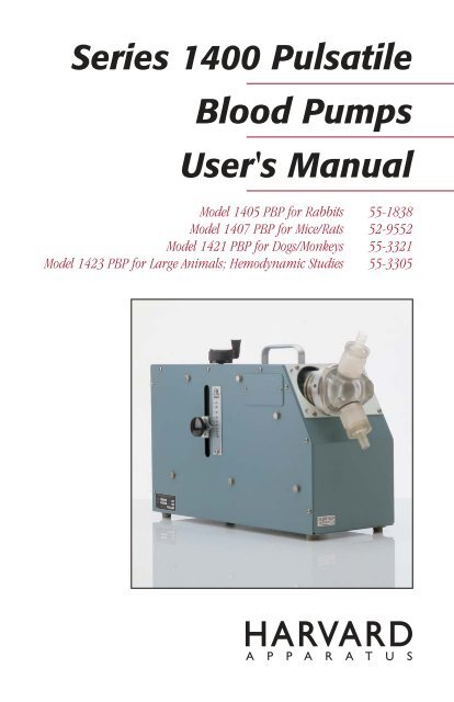
<strong>Series</strong> <strong>1400</strong> <strong>Pulsatile</strong><br />
<strong>Blood</strong> <strong>Pumps</strong><br />
User's <strong>Manual</strong><br />
Model 1405 PBP for Rabbits 55-1838<br />
Model 1407 PBP for Mice/Rats 52-9552<br />
Model 1421 PBP for Dogs/Monkeys 55-3321<br />
Model 1423 PBP for Large Animals; Hemodynamic Studies 55-3305
1<br />
Table of Contents<br />
H a r v a r d A p p a r a t u s S e r i e s 1 4 0 0 P u l s a t i l e B l o o d P u m p s U s e r ' s M a n u a l<br />
SUBJECT<br />
PAGE<br />
Warranty and Repair Information ........................2<br />
Theory of Operation ..............................................3<br />
Specifications ........................................................4<br />
Operation ............................................................5–9<br />
Installing the Pump ............................................5<br />
Operation for All <strong>Pumps</strong> ....................................5<br />
Operating Controls:<br />
Stroke Volume Adjustment ............................6<br />
Rate Adjustment............................................6<br />
Output Phase Ratio ......................................6<br />
Dual Phase Rate Compensation Chart ..............7<br />
Models 1405 & 1407:<br />
Pumping Head ..............................................8<br />
Cleaning and Sterilization ............................8<br />
Lubrication ....................................................8<br />
Valves............................................................8<br />
Pump Mechanism ........................................8<br />
Models 1421 & 1423:<br />
Pumping Head ..............................................9<br />
Cleaning and Sterilization ............................9<br />
Lubrication ....................................................9<br />
Valves............................................................9<br />
Pump Mechanism ........................................9<br />
Control ..........................................................9<br />
Drawing and Parts List ..................................10-13<br />
Diagrams..........................................................14-15<br />
Data ......................................................................16
2<br />
Warranty and Repair Information<br />
H a r v a r d A p p a r a t u s S e r i e s 1 4 0 0 P u l s a t i l e B l o o d P u m p s U s e r ' s M a n u a l<br />
Serial Numbers<br />
All inquires concerning our product should refer to the serial number of the unit(s).<br />
Warranty<br />
<strong>Harvard</strong> <strong>Apparatus</strong> warranties the instrument(s) for a period of one year from date of<br />
purchase. At its option, <strong>Harvard</strong> <strong>Apparatus</strong> will repair or replace the unit(s) if it is<br />
found to be defective as to workmanship or material.<br />
This warranty does not extend to damage resulting from misuse, neglect or abuse,<br />
normal wear and tear, or accident.<br />
This warranty extends only to the original customer purchaser.<br />
IN NO EVENT SHALL HARVARD APPARATUS BE LIABLE FOR INCIDENTAL OR<br />
CONSEQUENTIAL DAMAGES. Some states do not allow exclusion or limitation of<br />
incidental or consequential damages so the above limitation or exclusion may not<br />
apply to you. THERE ARE NO IMPLIED WARRANTIES OF MERCHANTABILITY,<br />
OR FITNESS FOR A PARTICULAR USE, OR OF ANY OTHER NATURE. Some states<br />
do not allow this limitation on an implied warranty, so the above limitation may not<br />
apply to you.<br />
If a defect arises within the one-year warranty period, promptly contact <strong>Harvard</strong><br />
<strong>Apparatus</strong>, Inc. 84 October Hill Road, Holliston, Massachusetts 01746-1371<br />
using our U.S. only toll free number 1-800-272-2775 or dial (508) 893-8999. Goods<br />
will not be accepted for return unless an RMA (returned materials authorization)<br />
number has been issued by our customer service department. The customer is<br />
responsible for shipping charges. Please allow a reasonable period of time for completion<br />
of repairs, replacement and return. If the unit is replaced, the replacement<br />
unit is covered only for the remainder of the original warranty period dating from the<br />
purchase of the original device.<br />
This warranty gives you specific rights,and you may also have other rights which vary<br />
from state to state.<br />
Repair Facilities and Parts<br />
<strong>Harvard</strong> <strong>Apparatus</strong> stocks replacement and repair parts. When ordering, please<br />
describe parts as completely as possible, preferably using our part numbers. If practical,<br />
enclose a sample or drawing.We offer a complete reconditioning service.<br />
CAUTION: Not for clinical use on human patients.
3<br />
Theory of Operation<br />
H a r v a r d A p p a r a t u s S e r i e s 1 4 0 0 P u l s a t i l e B l o o d P u m p s U s e r ' s M a n u a l<br />
This family of four pumps, all similar in concept but differing in capacity, are intended<br />
to pump blood with minimum damage to blood cells. All pumps feature a mechanically<br />
activated piston moving back and forth in a transparent cylinder. The geometry<br />
of the piston actuation is such that the piston travels to the very end of the cylinder<br />
regardless of the stroke volume selected. This feature insures that blood is completely<br />
emptied from the cylinder at each stroke.<br />
The valve cages and liquid pathway have been carefully designed to provide a streamlined<br />
flow with no sharp edge to minimize hemolysis.<br />
All parts of the liquid pathway can be disassembled for cleaning and sterilization. In<br />
all pumps the volume per stroke and the strokes per minute can be adjusted while<br />
the pumps are running.<br />
The two smaller pumps #1405 and #1407 have mechanically fixed systole/diastole<br />
ratios of .33, that is, diastole lasts twice as long as systole. The larger pumps #1421<br />
and #1423 have electronically variable ratios in which systole can be adjusted to be<br />
25 to 50% of the total pumping cycle.
4<br />
Specifications<br />
H a r v a r d A p p a r a t u s S e r i e s 1 4 0 0 P u l s a t i l e B l o o d P u m p s U s e r ' s M a n u a l<br />
The specifications of all pumps are compared in the following chart.<br />
<strong>Harvard</strong> <strong>Pulsatile</strong> <strong>Blood</strong> Pump Comparison Chart<br />
Catalog No. 52-9552 55-1838 55-3321 55-3305<br />
Model No. 1407 1405 1421 1423<br />
Stroke Volume 0.05 to 1.0 ml 0.5 to 10.0 ml 4 to 30 ml 15 to 100 ml<br />
Stroke Rate<br />
(per min) 20 to 200 20 to 200 20 to 200 10 to 100<br />
Minimum Volume<br />
(vol x rate) 1 to 200 ml 5 ml to 2.0 liters 80 ml to 6 liters 150 ml to 10 liters<br />
Phasing Fixed Phase Fixed Phase Adjustable Phase Adjustable Phase<br />
35% systole 35% systole 35 to 50% 35 to 50%<br />
65% diastole 65% diastole of total cycle of total cycle<br />
Tube Size (ID) 5/16 in 5/16 in 1/2 in 5/8 in<br />
Piston Diameter 1/4 in 3/4 in 1-1/8 in 2 in<br />
Ball Valve Diameter 5/16 in 5/16 in 1/2 in 5/8 in<br />
Dimensions 312 x 156 x 250 mm 312 x 156 x 250 mm 500 x 212 x 337 mm 500 x 212 x 337 mm<br />
(12.5 x 6.25 x 10 in) (12.5 x 6.25 x 10 in) (20 x 8.5 x 13.5 in) (20 x 8.5 x 13.5 in)<br />
Weight 7.3 kg (16 lb) 7.3 kg (16 lb) 13.6 kg (30 lb) 14.5 kg (32 lb)<br />
Power Used 50 W 50 W 85 W 85 W<br />
Voltage 115/230 V 115/230 V 115 V 115 V<br />
50-60 Hz 50-60 Hz 50-60 Hz 50-60 Hz<br />
Application Mice/Rats Rabbits Dogs/Monkeys Large Animals;<br />
Hemodynamic<br />
Studies
5<br />
Operation<br />
H a r v a r d A p p a r a t u s S e r i e s 1 4 0 0 P u l s a t i l e B l o o d P u m p s U s e r ' s M a n u a l<br />
Installing the Pump<br />
Both of the smaller pumps #1405 and #1407 are equipped with a voltage selector<br />
switch for either 120 or 220 volt usage. BE SURE THIS SWITCH IS SET FOR YOUR<br />
VOLTAGE.<br />
For 220 volt operation the American line cord plug must be cut-off and an appropriate<br />
plug installed. The line cord is color coded in International standard colors.<br />
Brown – High<br />
Blue – Neutral<br />
Green – Ground<br />
Observe these polarities. PUMPS ARE NOT EXPLOSION PROOF.<br />
Operation for All <strong>Pumps</strong><br />
The inlet nozzle is always at the bottom of the pump head. <strong>Pumps</strong> are self-priming<br />
and will lift liquids from reservoirs up to 50 centimeters below the inlet.<br />
Since the valves of the pump are passive ball valves liquid will flow thru the pump<br />
without the pump running if –<br />
1. The inlet reservoir is above the outlet<br />
2. The inlet pressure is higher than the outlet pressure<br />
3. The outlet tubing is below the inlet, this can cause siphoning or gravity<br />
induced flow<br />
The volume pumped per minute is called the “minute volume”. It is the product of<br />
the stroke volume times the stroke rate. This is only valid if there is a normal amount<br />
of back pressure or resistance to flow. Since the pumped liquid has inertia,liquid will<br />
continue to flow even in the filling cycle. This can be prevented by having adequate<br />
resistance in the output circuit.
6<br />
Operation<br />
H a r v a r d A p p a r a t u s S e r i e s 1 4 0 0 P u l s a t i l e B l o o d P u m p s U s e r ' s M a n u a l<br />
Operating Controls<br />
Stroke Volume Adjustment<br />
On smaller pumps the volume is set by turning the stroke volume control located at<br />
the top of the pump. Volume is read from the decal fastened to the pump cylinder.<br />
Volume is determined by watching the excursion of one “O” ring. Volume should be<br />
adjusted while the pump is running. A thumb screw is built-in to the volume control<br />
to provide positive locking once the volume is set.<br />
On larger pumps the volume control is at the top while the actual volume is read<br />
from a calibrated plate on the side of the pump. A locking knob next to the volume<br />
pointer provides positive locking.<br />
Rate Adjustment (strokes per min)<br />
On small pumps the rate control is at the top of the pump, on large pumps the rate<br />
control is at the end of the pump opposite the pump head.<br />
Output Phase Ratio<br />
The larger pumps are equipped with a control to adjust the ratio of systole to diastole.<br />
This control is located adjacent to the rate control. The control is continuously<br />
variable from 25/75 to 50/50. In the 25/75 position, systole takes place in 25% of the<br />
cardiac cycle while diastole takes place in 75%. This is observed by watching the piston/cylinder<br />
eject liquid quickly and fill slowly in the 25/75 position. In the 50/50<br />
position the piston speed is the same in filling and emptying.<br />
The phase ratio has an affect on the rate control (see figure 1 on next page). The<br />
observed stroke rate varies considerably from the set rate as the phase ratio reaches<br />
its outer limits.
7<br />
Operation<br />
H a r v a r d A p p a r a t u s S e r i e s 1 4 0 0 P u l s a t i l e B l o o d P u m p s U s e r ' s M a n u a l<br />
Actual rate in strokes per min<br />
50<br />
40<br />
30<br />
20<br />
10<br />
0<br />
0 10 20 30 40 50<br />
Rate on strokes per min dial<br />
Figure 1. Dual Phase Rate Compensation Chart.<br />
Phase ratio (% systole); typical plot of actual stroke rate at various<br />
ratios and strokes.<br />
50/50<br />
45/55<br />
40/60<br />
35/65<br />
30/70<br />
25/75
8<br />
Operation: Models 1405 & 1407<br />
H a r v a r d A p p a r a t u s S e r i e s 1 4 0 0 P u l s a t i l e B l o o d P u m p s U s e r ' s M a n u a l<br />
Care and Maintenance<br />
Disconnect from the power source before performing any motor maintenance.<br />
Pumping Head<br />
The Pumping Head is easily removed for cleaning, sterilization and lubrication. Refer<br />
to the diagram for part designation on the Standard 10 cc #1405 Pumping Head.<br />
Follow the instructions below for removing the Head:<br />
1. Using the Stroke Rate and Stroke Volume Controls allow the Piston to recede to<br />
the furthest end of its travel. (Note:The stroke volume control should be set for<br />
maximum volume delivery).<br />
2. Remove the thumbscrews attaching the cylinder and the valve head.<br />
3. Gently pull the Cylinder away from the black plate until it clears the short binding<br />
posts extending from this plate.<br />
4. Slide the Head and Cylinder assembly off the piston.<br />
5. If Piston removal is desired, hold the Piston in one hand and use a small openend<br />
wrench to loosen the hex Coupling. The Piston can then be unscrewed<br />
from the Coupling.<br />
Cleaning and Sterilization<br />
For non-sterile applications, clean parts from all residues with water and a damp<br />
cloth. Flush the head and valves before reassembly to make sure that all cloth fibers<br />
and other materials are cleared. For sterile applications, either gas or cold sterilization<br />
agents can be used.<br />
Lubrication<br />
Apply a light coating of the silicone grease provided to the Piston and the inside of<br />
the Cylinder.<br />
Valves<br />
The Valves are easily disassembled for cleaning. The ‘O’ rings can be removed for<br />
cleaning and replacement. Refer to the drawing when the components are to be<br />
reassembled.<br />
Pump Mechanism<br />
The entire pump mechanism is available for inspection and lubrication by removing<br />
the bottom cover and the control panel assembly. The bottom cover is removed by<br />
loosening the screws within the four rubber feet. The control panel assembly is<br />
removed by (1) loosening the set screw on the Stroke Volume Control and removing<br />
the knob, (2) removing the eight Phillips-type screws connecting the panel assembly<br />
to the housing, and (3) lifting the panel assembly clear of the stroke control shaft.<br />
IMPORTANT: Make sure that the wires remain connected to their appropriate terminals.<br />
All bearings and points of frictional contact should be lubricated every 30<br />
days with a light machine oil (<strong>Harvard</strong> Part No. 0606-060).
9<br />
Operation: Models 1421 & 1423<br />
H a r v a r d A p p a r a t u s S e r i e s 1 4 0 0 P u l s a t i l e B l o o d P u m p s U s e r ' s M a n u a l<br />
Care and Maintenance<br />
Disconnect from the power source before performing any motor maintenance.<br />
Pumping Head<br />
The Pump Head is easily removed for cleaning, sterilization, and lubrication. Refer to<br />
diagrams for part designation on the #1421 and #1423 Pumping Heads, respectively.<br />
Follow the instructions below for removing the head:<br />
1. Using the spanner wrench provided,insert the wrench-pin into one of the holes<br />
in the Nut-Coupling, apply pressure, and loosen. The coupling can now be easily<br />
removed from the cylinder.<br />
2. Using the same wrench,insert the wrench-pin into one of the holes on the cylinder,<br />
apply pressure, and loosen. Proceed to unscrew the cylinder manually.<br />
3. To remove the Piston, insert the wrench-pin into one of the holes on the Piston,<br />
apply pressure, and loosen. Remove the Piston manually.<br />
Cleaning and Sterilization<br />
For non-sterile applications, clean parts from all residues with water and a damp<br />
cloth. Make certain that all cloth fibers are cleared from the system before it is<br />
reassembled. For sterile applications, either gas or cold sterilization agents can be<br />
used.<br />
Lubrication<br />
Apply a light coating of the silicone grease provided to the Piston and the inside of<br />
the Cylinder.<br />
Valves<br />
The Valves are easily disassembled for cleaning. The ‘O’ rings can be removed for<br />
cleaning and replacement. Refer to the drawing when the components are to be<br />
reassembled.<br />
Pump Mechanism<br />
The entire Pump Mechanism is available for inspection and lubrication by removing<br />
the blank side panel. All bearings and points of frictional contact should be lubricated<br />
every 30 days with a light machine oil (<strong>Harvard</strong> Part No. 0606-060).<br />
Control<br />
The solid state dual phase Motor Control needs no special attention. If a problem<br />
seems to exist in the motor control, the unit should only be examined by a qualified<br />
technician. A safety fuse (1 amp.slo-blo type) is provided for overload protection. DO<br />
NOT REPLACE with a higher rated fuse.
10<br />
Drawing and Parts List (1 cc)<br />
H a r v a r d A p p a r a t u s S e r i e s 1 4 0 0 P u l s a t i l e B l o o d P u m p s U s e r ' s M a n u a l<br />
1 cc Standard Pumping Head / 52-9552 / 1407<br />
1405-046<br />
1405-045<br />
1405-044<br />
5013-034<br />
5011-019<br />
1405-043<br />
1407-012<br />
0 .5 1<br />
Part No.<br />
1407-013<br />
0680-067<br />
5013-016<br />
Replacement Part<br />
0680-067 Coupling<br />
1407-013 Piston<br />
1405-044 Body–Valve<br />
1405-045 Nozzle–Suction<br />
1407-012 Cylinder<br />
1405-046 Nozzle–Discharge<br />
5011-019 Ball–SS Bearing, Hard<br />
5013-016 O Ring, Parker #0125-070<br />
5013-019 O Ring, Parker #2-13<br />
1405-043 Head
11<br />
Drawing and Parts List (10 cc)<br />
H a r v a r d A p p a r a t u s S e r i e s 1 4 0 0 P u l s a t i l e B l o o d P u m p s U s e r ' s M a n u a l<br />
10 cc Standard Pumping Head / 55-1838 / 1405<br />
1405-046<br />
5013-034<br />
1405-042 1405-011<br />
1405-010<br />
1405-044<br />
0 .5 10<br />
0680-067<br />
5013-018<br />
5011-019<br />
1405-045<br />
Part No. Replacement Part<br />
0680-067 Coupling<br />
1405-010 Piston<br />
1405-044 Body–Valve<br />
1405-045 Nozzle–Suction<br />
1405-046 Nozzle–Discharge<br />
1405-042 Assy–Valve HD & Cylinder<br />
5011-019 Ball–SS Bearing, Hard<br />
5013-018 O Ring, Parker #2-16<br />
5013-019 O Ring, Parker #2-13
12<br />
Drawing and Parts List (30 cc)<br />
H a r v a r d A p p a r a t u s S e r i e s 1 4 0 0 P u l s a t i l e B l o o d P u m p s U s e r ' s M a n u a l<br />
30 cc Standard Pumping Head / 55-3321 / 1421<br />
1401-033<br />
5013-021<br />
1401-010<br />
5013-014<br />
1401-014<br />
1401-032 5115-011<br />
1401-030<br />
1401-015<br />
5013-032<br />
1401-008<br />
5124-001<br />
1401-031<br />
Part No. Replacement Part<br />
1401-008 Cylinder<br />
1401-030 Head–Valve<br />
1401-010 Nut–Coupling<br />
1401-031 Nozzle–Suction<br />
1401-032 Body–Valve<br />
1401-033 Nozzle–Discharge<br />
1401-014 Piston<br />
1401-015 Shaft–Connecting<br />
5013-014 O Ring, Parker #2-126<br />
5013-021 O Ring, Parker #2-18<br />
5013-032 O Ring, Parker #2-119<br />
5115-011 Set Screw #8, 32 x 3/16<br />
5124-001 Sphere, 1/2 D
13<br />
Drawing and Parts List (100 cc)<br />
H a r v a r d A p p a r a t u s S e r i e s 1 4 0 0 P u l s a t i l e B l o o d P u m p s U s e r ' s M a n u a l<br />
100 cc Standard Pumping Head / 55-3305 / 1423<br />
1403-022<br />
5013-037<br />
1403-010<br />
5013-028<br />
1403-014<br />
1403-021 5115-011<br />
1403-019<br />
1403-015<br />
5013-029<br />
1403-008<br />
5124-002<br />
1403-020<br />
Part No. Replacement Part<br />
1403-008 Cylinder<br />
1403-019 Head–Valve<br />
1403-010 Nut–Coupling<br />
1403-020 Nozzle–Suction<br />
1403-021 Body–Valve<br />
1403-022 Nozzle–Discharge<br />
1403-014 Piston<br />
1401-015 Shaft–Connecting<br />
5013-028 O Ring, Parker #2-140<br />
5013-029 O Ring, Parker #2-133<br />
5013-037 O Ring, Parker #2-24<br />
5115-011 Set Screw #8, 32 x 3/16<br />
5124-002 Sphere, 3/4 D
14<br />
Diagrams<br />
H a r v a r d A p p a r a t u s S e r i e s 1 4 0 0 P u l s a t i l e B l o o d P u m p s U s e r ' s M a n u a l<br />
Typical Pump Head<br />
Transparent<br />
Acrylic Chamber<br />
Silicone<br />
Ball-Check<br />
Valves<br />
Output<br />
Input<br />
Polycarbonate<br />
Nozzle<br />
Transparent Acrylic<br />
Valvecage<br />
Aluminum<br />
Coupling Nut<br />
Teflon Coated<br />
Piston<br />
Fluoro Elastomer<br />
“O” Rings<br />
Transparent<br />
Acrylic Cylinder
15<br />
Diagrams<br />
H a r v a r d A p p a r a t u s S e r i e s 1 4 0 0 P u l s a t i l e B l o o d P u m p s U s e r ' s M a n u a l<br />
Single Phase Motor Speed Control<br />
(Models 1405 & 1407)<br />
BLACK #18<br />
L2<br />
BLACK<br />
BLACK<br />
DS1<br />
F1<br />
FUSE SLOW BLOW<br />
BROWN #18<br />
MC1<br />
L1<br />
S3<br />
S2<br />
S1<br />
PILOT LIGHT<br />
WHITE #18<br />
W1<br />
PLUG AC MALE<br />
BLUE #18<br />
L1 A1 A2 F1 F2<br />
S1<br />
POWER SWITCH<br />
GREEN/YELLOW #18<br />
BLACK #18<br />
GREEN #18<br />
BLACK #18<br />
BLUE #18<br />
GROUND LUG<br />
MAIN CHASIS<br />
RED<br />
BLUE #18<br />
GROUND LUG<br />
FRONT PANEL<br />
Catalog No. Model No. Power<br />
M1<br />
MOTOR<br />
VR101<br />
GREEN<br />
100K<br />
SPEED<br />
BLACK<br />
55-1838 1405 115/240 VAC, 50–60 Hz (1 AMP)<br />
55-3321 1421 115 VAC, 60 Hz (1 AMP)<br />
55-3339 1421A 240 VAC, 50 Hz (1/2 AMP)<br />
55-3305 1423 115 VAC, 60 Hz (1 AMP)<br />
55-3313 1423A 240 VAC, 50 Hz (1/2 AMP)<br />
52-9552 1407 115/240 VAC, 50–60 Hz (1 AMP)
16<br />
Data<br />
H a r v a r d A p p a r a t u s S e r i e s 1 4 0 0 P u l s a t i l e B l o o d P u m p s U s e r ' s M a n u a l<br />
Hemolysis Test Data (Models 1421 & 1423)<br />
In these studies a reservoir of 500 to 800 cc of fresh dog blood was used, connected<br />
to the pump by 3/8" PVC tubing. Samples at room temperature were taken at 15 and<br />
30 minute intervals for 4 to 5 hours. Samples were spun down and hemolysis measured<br />
immediately using the method of FLINK & WATSON. Since the rate of hemolysis<br />
depends on the amount of blood in the system and the flow rate, the results are<br />
reported as mg % per pass. The flow rate divided by the volume of blood in the system<br />
determines the number of passes through the pump per minute.<br />
Hemolysis ranged from 0.114 mg % to 0.27 mg % per hour pass through the various<br />
pumps with an error of ± 10%.<br />
To put these results in perspective most physiological perfusions are run with flow<br />
rates and total blood primes, so that the number of passes through the pump will<br />
range from about 1/4 to 3/4 per minute. Assuming one pass in two minutes and no<br />
physiological removal of the products of hemolysis,then hemolysis rates would range<br />
from 3.4 mg % to 8.7 mg % per hour of pump use.