HARTING News 2013
HARTING News 2013
HARTING News 2013

Create successful ePaper yourself
Turn your PDF publications into a flip-book with our unique Google optimized e-Paper software.
<strong>HARTING</strong> <strong>News</strong> <strong>2013</strong>
<strong>HARTING</strong> worldwide<br />
Introduction<br />
Transforming customer wishes<br />
into concrete solutions<br />
The <strong>HARTING</strong> Technology Group is skilled in the fields of electrical, electronic and optical<br />
connection, transmission and networking, as well as in manufacturing, mechatronics and<br />
software creation. The Group uses these skills to develop customized solutions and products<br />
such as connectors for energy and data transmission applications including, for example,<br />
mechanical engineering, rail technology, wind energy plants, factory automation and the<br />
telecommunications sector. In addition, <strong>HARTING</strong> also produces electro-magnetic components<br />
for the automobile industry and offers solutions in the field of Enclosures and Shop Systems.<br />
The <strong>HARTING</strong> Group currently comprises 36 subsidiary companies and worldwide distributors<br />
employing a total of approximately 3,500 staff.<br />
2
Introduction<br />
<strong>HARTING</strong> Subsidiary company<br />
<strong>HARTING</strong> Representatives<br />
We aspire to top performance.<br />
Connectors ensure functionality. As core elements<br />
of electrical and optical wiring, connection and<br />
infrastructure technologies, they are essential in<br />
enabling the modular construction of devices, machines<br />
and systems across a very wide range of industrial<br />
applications. Their reliability is a crucial factor<br />
guaranteeing smooth functioning in the manufacturing<br />
area, in telecommunications, applications in medical<br />
technology – in fact, connectors are at work in virtually<br />
every conceivable application area. Thanks to the<br />
consistent further development of our technologies,<br />
customers enjoy investment security and benefit from<br />
durable, long term functionality.<br />
Always at hand, wherever our customers may be.<br />
Increasing industrialization is creating growing<br />
markets characterized by widely diverging demands and<br />
requirements. The search for perfection, increasingly<br />
efficient processes and reliable technologies is a common<br />
factor in all sectors across the globe.<br />
<strong>HARTING</strong> is providing these technologies – in Europe,<br />
America and Asia. The <strong>HARTING</strong> professionals at our<br />
international subsidiaries engage in close, partnership<br />
based interaction with our customers, right from the very<br />
early product development phases, in order to realize<br />
customer demands and requirements in the best possible<br />
manner.<br />
Our people on location form the interface to the centrally<br />
coordinated development and production departments.<br />
In this way, our customers can rely on consistently high,<br />
superior product quality – worldwide.<br />
Our claim: pushing performance.<br />
<strong>HARTING</strong> provides more than optimally attuned<br />
components. In order to serve our customers with the best<br />
possible solutions, <strong>HARTING</strong> is able to contribute a great<br />
deal more and play a closely integrative role in the value<br />
creation process.<br />
From ready assembled cables through to control racks<br />
or ready-to-go control desks: Our aim is to generate<br />
the maximum benefits for our customers – without<br />
compromise!<br />
Quality creates reliability – and warrants trust.<br />
The <strong>HARTING</strong> brand stands for superior quality and<br />
reliability – worldwide. The standards we set are the<br />
result of consistent, stringent quality management that is<br />
subject to regular certifications and audits.<br />
EN ISO 9001, the EU Eco-Audit and ISO 14001:2004 are<br />
key elements here. We take a proactive stance to new<br />
requirements, which is why <strong>HARTING</strong> ranks among the<br />
first companies worldwide to have obtained the new IRIS<br />
quality certificate for rail vehicles.<br />
3
<strong>HARTING</strong> worldwide<br />
Introduction<br />
<strong>HARTING</strong> technology creates added value for customers.<br />
Technologies by <strong>HARTING</strong> are at work worldwide.<br />
<strong>HARTING</strong>’s presence stands for smoothly functioning<br />
systems, powered by intelligent connectors, smart<br />
infrastructure solutions and mature network systems. In<br />
the course of many years of close, trust-based cooperation<br />
with its customers, the <strong>HARTING</strong> Technology Group has<br />
advanced to one of the worldwide leading specialists<br />
for connector technology. Extending beyond the basic<br />
functionalities demanded, we offer individual customers<br />
specific and innovative solutions. These tailored solutions<br />
deliver sustained effects, provide investment security and<br />
enable customers to achieve strong added value.<br />
Opting for <strong>HARTING</strong> opens up an innovative, complex<br />
world of concepts and ideas.<br />
In order to develop connectivity and network solutions<br />
serving an exceptionally wide range of connector<br />
applications and task scopes in a professional and cost<br />
optimized manner, <strong>HARTING</strong> not only commands the full<br />
array of conventional tools and basic technologies. Over<br />
and beyond these capabilities, <strong>HARTING</strong> is constantly<br />
harnessing and refining its broad base of knowledge<br />
and experience to create new solutions that ensure<br />
continuity at the same time. In securing this know-how<br />
lead, <strong>HARTING</strong> draws on a wealth of sources from both inhouse<br />
research and the world of applications alike.<br />
Salient examples of these sources of innovative knowledge<br />
include microstructure technologies, 3D design and<br />
construction technology, as well as high temperature<br />
or ultrahigh frequency applications that are finding use<br />
in telecommunications or automation networks, in the<br />
automotive industry, or in industrial sensor and actuator<br />
applications, RFID and wireless technologies, in addition<br />
to packaging and housing made of plastics, aluminum or<br />
stainless steel.<br />
<strong>HARTING</strong> solutions extend across technology boundaries.<br />
Drawing on the comprehensive resources of the group’s<br />
technology pool, <strong>HARTING</strong> devises practical solutions<br />
for its customers. Whether this involves industrial<br />
networks for manufacturing automation, or hybrid<br />
interface solutions for wireless telecommunication<br />
infrastructures, 3D circuit carriers with microstructures,<br />
or cable assemblies for high-temperature applications<br />
in the automotive industry – <strong>HARTING</strong> technologies<br />
offer far more than components, and represent mature,<br />
comprehensive solutions attuned to individual customer<br />
requirements and wishes. The range covers ready-to-use<br />
cable configurations, completely assembled backplanes<br />
and board system carriers, as well as fully wired and<br />
tested control panels.<br />
In order to ensure the future proof design of RF- and<br />
EMC-compatible interface solutions, the central <strong>HARTING</strong><br />
laboratory (certified to EN 45001) provides simulation<br />
tools, as well as experimental, testing and diagnostics<br />
facilities all the way through to scanning electron<br />
microscopes. In the selection of materials and processes,<br />
lifecycle and environmental aspects play a key role, in<br />
addition to product and process capability considerations.<br />
4
Introduction<br />
<strong>HARTING</strong> knowledge is practical know-how generating<br />
synergy effects.<br />
<strong>HARTING</strong> commands decades of experience with<br />
regard to the applications conditions of connectors in<br />
telecommunications, computer and network technologies<br />
and medical technologies, as well as industrial automation<br />
technologies, such as the mechanical engineering<br />
and plant engineering areas, in addition to the power<br />
generation industry or the transportation sector. <strong>HARTING</strong><br />
is highly conversant with the specific application areas in<br />
all of these technology fields.<br />
The key focus is on applications in every solution<br />
approach. In this context, uncompromising, superior<br />
quality is our hallmark. Every new solution found will<br />
invariably flow back into the <strong>HARTING</strong> technology pool,<br />
thereby enriching our resources. And every new solution<br />
we go on to create will draw on this wealth of resources<br />
in order to optimize each and every individual solution. In<br />
this way, <strong>HARTING</strong> is synergy in action.<br />
Telecom<br />
Machinery<br />
Transportation Solar Energy<br />
Assembly lines<br />
Backplanes<br />
Embedded Computing Systems<br />
Wind Energy<br />
3D Micropackages<br />
PCB<br />
Technologies<br />
Production<br />
Technologies<br />
Metal Treatment<br />
Technologies<br />
Industrial Connectors<br />
Broadcast and Entertainment<br />
Power Generation and Distribution<br />
Advanced Tools<br />
Simulation<br />
Interconnect<br />
Technologies<br />
Mechatronic<br />
Micro Structure<br />
Technologies<br />
Actuator Systems<br />
Vending Systems<br />
Information<br />
Technologies<br />
Network<br />
Technologies<br />
Cable Assemblies<br />
Automation<br />
Medical Industrial Network Infrastructure<br />
Industrial Devices<br />
5
<strong>HARTING</strong> <strong>News</strong><br />
Contents<br />
Page<br />
Installation Technology<br />
Han ® High Temp Connector for high Temperatures. ............... 11<br />
Han ® High Temp Size 6 B. ............................... 13<br />
Han ® High Temp Size 10 B. .............................. 15<br />
Han ® High Temp Size 16 B. .............................. 17<br />
Han ® High Temp Size 24 B. .............................. 19<br />
Han ® 16 B Hood with M50 cable entry ......................... 21<br />
Han ® B bulkhead mounted housing, IP 67 ...................... 23<br />
Han ® HMC Connectors for High Mating Cycles .................. 26<br />
Han D ® HMC / Han DD ® HMC ............................ 27<br />
Han E ® HMC / Han ® EEE HMC ........................... 37<br />
Han-Modular ® ........................................ 47<br />
Han ® HMC Hoods/housings ............................. 63<br />
Han ® HMC Acessories. ................................. 70<br />
Han-Yellock ® Outdoor ...................................... 72<br />
Han-Modular ®<br />
Han-Modular ® LC module. ............................... 75<br />
Han-Modular ® E screw module. ........................... 77<br />
Han-Modular ® Docking frame ............................. 79<br />
Han-Modular ® Module clamp ............................. 82<br />
Han-Port ® Frame .......................................... 83<br />
6<br />
Han ® Q<br />
Han ® Q High Density ................................... 86<br />
Han ® Q 3/0 Crimp ...................................... 89<br />
Han ® Q 4/0 Crimp ...................................... 91
<strong>HARTING</strong> <strong>News</strong><br />
Contents<br />
Page<br />
Han ® HPR<br />
Han ® 3 HPR Cover ..................................... 93<br />
Han ® 24 HPR EasyCon Carrier Frame. ..................... 95<br />
Han ® HC Individual<br />
Han ® HC Individual .................................... 97<br />
Han ® HC Individual Acessories. ........................... 99<br />
Han ® HC Individual Contacts ............................. 101<br />
Han ® HC Individual Sets. ................................ 102<br />
Han ® HC Individual Assembly and Construction .............. 103<br />
<strong>HARTING</strong> Hall-Effekt Current Sensors Eco Series ................ 105<br />
Han ® Tools<br />
Crimp tool Han-Fast ® Lock ............................... 108<br />
Han-Modular ® Removal tool .............................. 109<br />
Han ® Torque Tool Set for high current axial screw contacts ...... 110<br />
Han ® Torque Tool Set for power contacts .................... 111<br />
Han ® Torque Tool Set for <strong>HARTING</strong> screw contacts and fixing screws 112<br />
Han ® VDE Screw Driver Set ............................. 113<br />
Automation IT<br />
Ha-VIS Middleware . ....................................... 115<br />
Ha-VIS RF-R200 Reader ................................... 117<br />
Ha-VIS mCon 3000 Next Generation .......................... 120<br />
Ha-VIS mCon 3000 Next Generation . . . . . . . . . . . . . . . . . . . . . . . 122<br />
Ha-VIS mCon 3080-A ................................... 125<br />
Ha-VIS mCon 3102-AASFP .............................. 126<br />
Ha-VIS Accessories - Memory Cards ....................... 127<br />
Ha-VIS SFP Modules ................................... 128<br />
7
<strong>HARTING</strong> <strong>News</strong><br />
Contents<br />
Page<br />
Device Connectivity<br />
DIN 41612 connectors<br />
Technical characteristics for types 3Q and 3R ................ 131<br />
Male connectors of complementary type 3Q ................. 132<br />
Male connectors of complementary type 3R. ................. 134<br />
Shrouds for type F ..................................... 136<br />
series<br />
Hoods for bellows male connectors ........................ 137<br />
series<br />
Technical characteristics. ................................ 138<br />
Male and female connectors. ............................. 139<br />
D-Sub series<br />
Turned crimp contacts .................................. 140<br />
Technical characteristics for D-Sub SMT<br />
with straight solder terminations ........................... 141<br />
D-Sub SMT connectors with straight solder terminations. ....... 142<br />
D-Sub SMT connectors<br />
with straight solder terminations and grounding pins ........... 144<br />
Cables<br />
Flat cables for insulation displacement termination,<br />
types SEK and D-Sub. .................................. 146<br />
Ha-VIS data bus cables ................................. 147<br />
PRORFINET cables .................................... 150<br />
Han ® SFP fibre optic cables and accessories ................ 152<br />
Ha-VIS preLink ®<br />
preLink ® Extender and terminal module ..................... 154<br />
8<br />
<strong>HARTING</strong> RJ Industrial ®<br />
RJ45 jacks with transformer . . . . . . . . . . . . . . . . . . . . . . . . . . . . . . 155
<strong>HARTING</strong> <strong>News</strong><br />
Contents<br />
Page<br />
Circular connectors<br />
har-speed adapter M12 - RJ45 and Gender changer. .......... 156<br />
har-speed with slim design ............................... 157<br />
har-flexicon ® series<br />
Pitches 1.27 mm / 2.54 mm<br />
PCB connectors female with IDC termination ............. 158<br />
PCB terminal blocks with push-in-spring-cage termination ... 160<br />
PCB connectors female with push-in-spring-cage termination 162<br />
PCB connectors male ............................... 164<br />
Pitches 3.50 mm / 3.81 mm<br />
PCB terminal blocks with push-in-spring-cage termination ... 166<br />
PCB terminal blocks with screw termination .............. 168<br />
PCB connectors female with push-in-spring-cage termination 170<br />
PCB connectors female with screw termination. ........... 172<br />
PCB connectors male ............................... 174<br />
Pitches 5.00 mm / 5.08 mm<br />
PCB terminal blocks with push-in-spring-cage termination ... 176<br />
PCB terminal blocks with screw termination .............. 178<br />
PCB connectors female with push-in-spring-cage termination 182<br />
PCB connectors female with screw termination. ........... 184<br />
PCB connectors male ............................... 186<br />
<strong>HARTING</strong> eCatalogue ......................................... 188<br />
Addresses . . . . . . . . . . . . . . . . . . . . . . . . . . . . . . . . . . . . . . . . . . . . . . . . . . 189<br />
9
10<br />
Notes
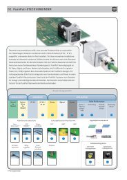
Han ® High Temp<br />
Description<br />
Han ® High Temp is a new product series that is based on our well-established Han ® B and Han ® E series.<br />
We used high-quality materials with wide temperature ranges to produce connectors that are uniquely suited<br />
for a wide variety of applications.<br />
These connectors can withstand temperatures up to 200 °C – so they can be used directly in machines and<br />
facilities that would otherwise require cumbersome and complex constructions.<br />
For our users, this delivers direct advantages:<br />
• The electro-mechanical design process is optimized.<br />
Machine parts which are exposed to high temperatures can be designed modularly.<br />
• The work process is optimized<br />
since lower wiring complexity results in reduced maintenance costs.<br />
• The after-sales phase is optimized<br />
because this more service-friendly approach results in less outages and down times.<br />
Design overview<br />
The basic structure of the Han ® High Temp connector consists<br />
of a bulkhead mounted housing and a cable-side hood.<br />
Hoods and housings:<br />
The aluminium die-cast hoods and housings feature a highly<br />
compressed surface with excellent non-stick properties. It<br />
also has a special non-stick coating on the bulkhead-side seal<br />
which allows easy handling without significant sticking.<br />
Inserts:<br />
The Han ® High Temp series features very rugged contact<br />
inserts, which are really the heart of any connector. The LCP<br />
injection-moulded insert delivers outstanding temperature<br />
resistance coupled with excellent mechanical stability.<br />
Contacts:<br />
Our new temperature resistant contacts, for either screw or<br />
crimp terminations, ensure reliable connections with minimal<br />
contact resistance even at extreme temperatures.<br />
Han ® High Temp connectors<br />
remain robust and reliable for their entire lifespan!<br />
11
Han ® High Temp<br />
Features<br />
• Reliable also at extreme temperatures up to<br />
200 °C<br />
• All piece parts (contacts, insert material, hoods<br />
and housings, seals and grounding elements) are<br />
designed in a temperature resistant way<br />
• Developed on the basis of the proven Han ® E series<br />
for 6, 10, 16 or 24 contacts<br />
• Electrical data for 16 A and 400 V<br />
Technical characteristics<br />
Specifications DIN EN 60 664-1<br />
DIN EN 61 984<br />
Inserts<br />
Number of contacts<br />
6, 10, 16, 24 + PE<br />
Electrical data<br />
acc. to EN 61 984 16 A 400 V 6 kV 3<br />
Rated current<br />
16 A<br />
Rated voltage<br />
400 V<br />
Rated impulse voltage 6 kV<br />
Pollution degree 3<br />
Insulation resistance<br />
≥ 10 10 Ω<br />
Material<br />
LCP<br />
Limiting temperatures -40 °C ... +200 °C<br />
Flammability acc. to UL 94 V 0<br />
Mechanical working life<br />
- mating cycles ≥ 500<br />
Current carrying capacity<br />
The current carrying capacity of the connectors is limited by<br />
the thermal load capability of the contact element material including<br />
the connections and the insulating parts. The derating<br />
curve is therefore valid for currents which flow constantly (nonintermittent)<br />
through each contact element of the connector<br />
evenly, without exceeding the allowed maximum temperature.<br />
Measuring and testing techniques according to<br />
DIN EN 60 512-5<br />
Operating current<br />
Contacts<br />
Material<br />
copper alloy<br />
Contact resistance<br />
≤ 1 mΩ<br />
Crimp termination - min. 0.5 mm²/ AWG 20<br />
Crimp termination - max. 2.5 mm²/ AWG 14<br />
Screw termination - min. 0.5 mm²/ AWG 20<br />
Screw termination - max. 2.5 mm²/ AWG 14<br />
Tigtening-/Testing torque 0.5 Nm<br />
Stripping length<br />
7 mm<br />
Hoods/housings<br />
Material<br />
aluminium die cast<br />
Surface<br />
unpainted<br />
Locking element<br />
stainless steel<br />
Hoods/housings seal<br />
FPM, red<br />
Limiting temperatures -40 °C ... +200 °C<br />
Degree of protection acc. to<br />
DIN EN 60 528<br />
for coupled connector IP 65<br />
Ambient temperature<br />
12<br />
1 wire gauge: 2.5 mm²
Han ® High Temp Size 6 B 400 V 16 A<br />
Number of contacts<br />
6 +<br />
Available September <strong>2013</strong><br />
Part number<br />
Identification Male insert (M) Female insert (F) Drawing Dimensions in mm<br />
Screw termination<br />
with wire protection<br />
09 33 806 2601<br />
09 33 806 2701<br />
a = 19.7 mm<br />
b = 34.7 mm<br />
c = 21.0 mm<br />
d = 37.0 mm<br />
1) Distance for contact max. 21 mm<br />
Crimp termination<br />
Crimp contacts<br />
order separately<br />
09 33 806 2602<br />
09 33 806 2702<br />
Contact arrangement<br />
view from<br />
termination side<br />
Panel cut out<br />
Wire gauge<br />
Part number<br />
Identification (mm²) Male contact Female contact Drawing Dimensions in mm<br />
Han ® High Temp contacts<br />
0.5<br />
0.75<br />
1.0<br />
1.5<br />
2.5<br />
09 33 800 6121<br />
09 33 800 6114<br />
09 33 800 6105<br />
09 33 800 6104<br />
09 33 800 6102<br />
09 33 800 6220<br />
09 33 800 6214<br />
09 33 800 6205<br />
09 33 800 6204<br />
09 33 800 6202<br />
Operating contact<br />
Identification<br />
0.5<br />
0.75<br />
1.0<br />
1.5<br />
2.5<br />
Wire gauge<br />
mm²<br />
mm²<br />
mm²<br />
mm²<br />
mm²<br />
AWG 20<br />
AWG 18<br />
AWG 18<br />
AWG 16<br />
AWG 14<br />
* on the back crimp collar<br />
Identification<br />
no groove<br />
1 groove*<br />
1 groove<br />
2 grooves<br />
3 grooves<br />
Stripping<br />
length<br />
7.5 mm<br />
7.5 mm<br />
7.5 mm<br />
7.5 mm<br />
7.5 mm<br />
13
Han ® High Temp Hoods/Housings Size 6 B<br />
Part number<br />
Cable entry<br />
Identification Low construction High construction metric Drawing Dimensions in mm<br />
Hood<br />
side entry<br />
19 62 806 1540<br />
1 x 20<br />
Hood<br />
side entry<br />
19 62 806 0546<br />
19 62 806 0547<br />
1 x 25<br />
1 x 32<br />
Hood<br />
top entry<br />
19 62 806 1440<br />
1 x 20<br />
Hood<br />
top entry<br />
19 62 806 0446<br />
19 62 806 0447<br />
1 x 25<br />
1 x 32<br />
Part number<br />
Cable entry<br />
Identification Low construction High construction metric Drawing Dimensions in mm<br />
Bulkhead mounted housing<br />
09 62 806 0391<br />
Panel cut out<br />
14
Han ® High Temp Size 10 B 400 V 16 A<br />
Number of contacts<br />
10 +<br />
Available September <strong>2013</strong><br />
Part number<br />
Identification Male insert (M) Female insert (F) Drawing Dimensions in mm<br />
Screw termination<br />
with wire protection<br />
09 33 810 2601<br />
09 33 810 2701<br />
a = 19.7 mm<br />
b = 34.7 mm<br />
c = 21.0 mm<br />
d = 37.0 mm<br />
1) Distance for contact max. 21 mm<br />
Crimp termination<br />
Crimp contacts<br />
order separately<br />
09 33 810 2602<br />
09 33 810 2702<br />
Contact arrangement<br />
view from<br />
termination side<br />
Panel cut out<br />
Wire gauge<br />
Part number<br />
Identification (mm²) Male contact Female contact Drawing Dimensions in mm<br />
Han ® High Temp contacts<br />
0.5<br />
0.75<br />
1.0<br />
1.5<br />
2.5<br />
09 33 800 6121<br />
09 33 800 6114<br />
09 33 800 6105<br />
09 33 800 6104<br />
09 33 800 6102<br />
09 33 800 6220<br />
09 33 800 6214<br />
09 33 800 6205<br />
09 33 800 6204<br />
09 33 800 6202<br />
Operating contact<br />
Identification<br />
0.5<br />
0.75<br />
1.0<br />
1.5<br />
2.5<br />
Wire gauge<br />
mm²<br />
mm²<br />
mm²<br />
mm²<br />
mm²<br />
AWG 20<br />
AWG 18<br />
AWG 18<br />
AWG 16<br />
AWG 14<br />
* on the back crimp collar<br />
Identification<br />
no groove<br />
1 groove*<br />
1 groove<br />
2 grooves<br />
3 grooves<br />
Stripping<br />
length<br />
7.5 mm<br />
7.5 mm<br />
7.5 mm<br />
7.5 mm<br />
7.5 mm<br />
15
Han ® High Temp Hoods/Housings Size 10 B<br />
Part number<br />
Cable entry<br />
Identification Low construction High construction metric Drawing Dimensions in mm<br />
Hood<br />
side entry<br />
19 62 810 1520<br />
1 x 20<br />
Hood<br />
side entry<br />
19 62 810 0526<br />
19 62 810 0527<br />
1 x 25<br />
1 x 32<br />
Hood<br />
top entry<br />
19 62 810 1420<br />
19 62 810 1421<br />
1 x 20<br />
1 x 25<br />
Hood<br />
top entry<br />
19 62 810 0426<br />
19 62 810 0427<br />
1 x 25<br />
1 x 32<br />
Part number<br />
Cable entry<br />
Identification Low construction High construction metric Drawing Dimensions in mm<br />
Bulkhead mounted housing<br />
09 62 810 0391<br />
Panel<br />
cut out<br />
16
Han ® High Temp Size 16 B 400 V 16 A<br />
Number of contacts<br />
16 +<br />
Available September <strong>2013</strong><br />
Part number<br />
Identification Male insert (M) Female insert (F) Drawing Dimensions in mm<br />
Screw termination<br />
with wire protection<br />
09 33 816 2601<br />
09 33 816 2701<br />
1) Distance for contact max. 21 mm<br />
a = 19.7 mm<br />
b = 34.7 mm<br />
c = 21.0 mm<br />
d = 37.0 mm<br />
Crimp termination<br />
Crimp contacts<br />
order separately<br />
09 33 816 2602<br />
09 33 816 2702<br />
Contact arrangement<br />
view from<br />
termination side<br />
Panel cut out<br />
Wire gauge<br />
Part number<br />
Identification (mm²) Male contact Female contact Drawing Dimensions in mm<br />
Han ® High Temp contacts<br />
0.5<br />
0.75<br />
1.0<br />
1.5<br />
2.5<br />
09 33 800 6121<br />
09 33 800 6114<br />
09 33 800 6105<br />
09 33 800 6104<br />
09 33 800 6102<br />
09 33 800 6220<br />
09 33 800 6214<br />
09 33 800 6205<br />
09 33 800 6204<br />
09 33 800 6202<br />
Operating contact<br />
Identification<br />
0.5<br />
0.75<br />
1.0<br />
1.5<br />
2.5<br />
Wire gauge<br />
mm²<br />
mm²<br />
mm²<br />
mm²<br />
mm²<br />
AWG 20<br />
AWG 18<br />
AWG 18<br />
AWG 16<br />
AWG 14<br />
* on the back crimp collar<br />
Identification<br />
no groove<br />
1 groove*<br />
1 groove<br />
2 grooves<br />
3 grooves<br />
Stripping<br />
length<br />
7.5 mm<br />
7.5 mm<br />
7.5 mm<br />
7.5 mm<br />
7.5 mm<br />
17
Han ® High Temp Hoods/Housings Size 16 B<br />
Part number<br />
Cable entry<br />
Identification Low construction High construction metric Drawing Dimensions in mm<br />
Hood<br />
side entry<br />
19 62 816 1521<br />
1 x 20<br />
Hood<br />
side entry<br />
19 62 816 0527<br />
1 x 32<br />
Hood<br />
top entry<br />
19 62 816 1421<br />
1 x 25<br />
Hood<br />
top entry<br />
19 62 816 0427<br />
1 x 32<br />
Part number<br />
Cable entry<br />
Identification Low construction High construction metric Drawing Dimensions in mm<br />
Bulkhead mounted housing<br />
09 62 816 0391<br />
Panel<br />
cut out<br />
18
Han ® High Temp Size 24 B 400 V 16 A<br />
Number of contacts<br />
24 +<br />
Available September <strong>2013</strong><br />
Part number<br />
Identification Male insert (M) Female insert (F) Drawing Dimensions in mm<br />
Crimp termination<br />
with wire protection<br />
09 33 824 2601<br />
09 33 824 2701<br />
1) Distance for contact max. 21 mm<br />
a = 19.7 mm<br />
b = 34.7 mm<br />
c = 21.0 mm<br />
d = 37.0 mm<br />
Screw termination<br />
Crimp contacts<br />
order separately<br />
09 33 824 2602<br />
09 33 824 2702<br />
Contact arrangement<br />
view from<br />
termination side<br />
Panel cut out<br />
Wire gauge<br />
Part number<br />
Identification (mm²) Male contact Female contact Drawing Dimensions in mm<br />
Han ® High Temp contacts<br />
0.5<br />
0.75<br />
1.0<br />
1.5<br />
2.5<br />
09 33 800 6121<br />
09 33 800 6114<br />
09 33 800 6105<br />
09 33 800 6104<br />
09 33 800 6102<br />
09 33 800 6220<br />
09 33 800 6214<br />
09 33 800 6205<br />
09 33 800 6204<br />
09 33 800 6202<br />
Operating contact<br />
Identification<br />
0.5<br />
0.75<br />
1.0<br />
1.5<br />
2.5<br />
Wire gauge<br />
mm²<br />
mm²<br />
mm²<br />
mm²<br />
mm²<br />
AWG 20<br />
AWG 18<br />
AWG 18<br />
AWG 16<br />
AWG 14<br />
* on the back crimp collar<br />
Identification<br />
no groove<br />
1 groove*<br />
1 groove<br />
2 grooves<br />
3 grooves<br />
Stripping<br />
length<br />
7.5 mm<br />
7.5 mm<br />
7.5 mm<br />
7.5 mm<br />
7.5 mm<br />
19
Han ® High Temp Hoods/Housings Size 24 B<br />
Part number<br />
Cable entry<br />
Identification Low construction High construction metric Drawing Dimensions in mm<br />
Hood<br />
side entry<br />
19 62 824 1521<br />
1 x 25<br />
Hood<br />
side entry<br />
19 62 824 0527<br />
19 62 824 0528<br />
1 x 32<br />
1 x 40<br />
Hood<br />
top entry<br />
19 62 824 1422<br />
1 x 32<br />
Hood<br />
top entry<br />
19 62 824 0427<br />
1 x 32<br />
Part number<br />
Cable entry<br />
Identification Low construction High construction metric Drawing Dimensions in mm<br />
Bulkhead mounted housing<br />
09 62 824 0391<br />
Panel<br />
cut out<br />
20
Han ® Standard Hood<br />
Features<br />
• High construction<br />
• Large cabling space<br />
• Cable entry with optimised 30° angle<br />
• Compatible to all standard hoods and housings<br />
Technical characteristics<br />
Material hood/housing<br />
aluminium die cast<br />
Colour<br />
RAL 7037 (grey)<br />
Surface<br />
powder coated<br />
Locking lever Han-Easy Lock ®<br />
Material Locking lever<br />
stainless steel<br />
Seal hood/housing<br />
NBR<br />
Limiting temperatures -40 °C ... +125 °C<br />
Approval acc. to UL 50<br />
in locked position IP 65<br />
21
Han ® Standard Hood<br />
Han ® 16 B hood with M50 cable entry<br />
Identification Part-Number M Drawing Dimensions in mm<br />
Hood<br />
side entry M40<br />
with 2 locking levers on the<br />
bulkhead mounted housing<br />
19 30 016 0523<br />
40<br />
Hood<br />
side entry M50<br />
with 2 locking levers on the<br />
bulkhead mounted housing<br />
19 30 016 0529<br />
50<br />
22
Han ® B Housings, bulkhead mounting, IP 67<br />
Available Juli <strong>2013</strong><br />
Features<br />
• Compatible to all standard hoods/housings<br />
• Approved lever locking system with Han-Easy<br />
Lock ®<br />
• Standard panel cut out<br />
• Degree of protection IP 66 and IP 67<br />
• No sliding off the seal due to the protective flange<br />
Technical Characteristics<br />
Han ® Standard Hoods/Housings<br />
Metal hoods/housings for industrial applications<br />
Material<br />
aluminium die-cast<br />
Colour<br />
RAL 7037 (grey)<br />
Surface<br />
powder-coated<br />
Locking element<br />
Stainless steel<br />
Lever type Han-Easy Lock ®<br />
Hoods/Housings seal NBR<br />
Limiting temperatures -40 °C ... +125 °C<br />
Degree of protection acc.<br />
to DIN EN 60 529<br />
for coupled connector IP 66 and IP 67<br />
23
Han ® B Housings, bulkhead mounting, IP 67<br />
Identification Part-Number Drawing Dimensions in mm<br />
Housings, bulkhead<br />
mounting 6 B<br />
09 30 006 1301<br />
Housings, bulkhead<br />
mounting 10 B<br />
09 30 010 1301<br />
Housings, bulkhead<br />
mounting 16 B<br />
09 30 016 1301<br />
Housings, bulkhead<br />
mounting 24 B<br />
09 30 024 1301<br />
24
Notes<br />
25
Han ® HMC Connectors for High Mating Cycles<br />
Features<br />
This series Han ® HMC (High Mating Cycles) is a connector series specifically aiming at<br />
industrial applications for 10,000 mating cycles.<br />
Benefits:<br />
• High mechanical robustness<br />
• Simple and easy understandable design<br />
• Optimized concept for signal and power transmission<br />
• Low mating and unmating forces<br />
• High contact density<br />
General Description<br />
Han ® B HMC hoods with high<br />
performance locking pin<br />
Ground contacts of crimp inserts<br />
with long lasting HMC contact<br />
spring<br />
Han D ® and Han E ® crimp<br />
contacts with specific HMC gold<br />
coating and a constant contact<br />
force<br />
Han ® B housings with Han-<br />
Easy Lock ® HMC locking lever<br />
26
Han D ® HMC<br />
Technical characteristics<br />
Hoods/Housings Han B ® HMC<br />
Material<br />
aluminium die-cast<br />
Surface<br />
powder coated<br />
RAL 7037 (grey)<br />
Locking element<br />
Han-Easy Lock ® HMC<br />
Flammability acc. to UL 94 V 0<br />
Hoods/Housings seal<br />
NBR<br />
Limiting temperatures -40 °C ... +125 °C<br />
Degree of protection acc. to DIN EN 60 529<br />
for coupled connector IP 65<br />
Features<br />
• High density contacts / connector<br />
• For requirements up to 250 V / 10 A<br />
• Time saving rapid termination by use of crimping<br />
contacts<br />
• Suitable for hoods/housings of series Han ® B<br />
HMC<br />
• Han D ® HMC contacts available with special<br />
HMC gold plating for 10,000 mating cycles<br />
Selection of hoods housings see page 53<br />
Specifications DIN EN 175 301-801<br />
DIN EN 60 664-1<br />
DIN EN 61 984<br />
Inserts<br />
Number of contacts<br />
40, 64 + PE<br />
Electrical data<br />
acc. to EN 61 984 10 A 250 V 4 kV 3<br />
Rated current<br />
10 A<br />
Rated voltage<br />
250 V<br />
Rated impulse voltage<br />
4 kV<br />
Pollution degree 3<br />
Pollution degree 2 also 10 A 230/400 V 4 kV 2<br />
– for wrap terminal only 10 A 250 V 4 kV 2<br />
Rated voltage<br />
acc. to UL/CSA<br />
600 V<br />
Insulation resistance<br />
≥ 10 10 Ω<br />
Material<br />
polycarbonate<br />
Limiting temperatures -40 °C ... +125 °C<br />
Flammability acc. to UL 94 V 0<br />
Mechanical working life<br />
- mating cycles ≥ 10,000<br />
Contacts Han D ® HMC<br />
Material<br />
copper alloy<br />
Surface<br />
HMC gold plating<br />
Contact resistance<br />
≤ 3 mΩ<br />
Crimp terminal - min 0.14 mm² / AWG 26<br />
Crimp terminal - max 2.5 mm² / AWG 14<br />
27
Han D ® HMC<br />
Technical characteristics<br />
Current carrying capacity<br />
The current carrying capacity of the connectors is limited by the thermal load capability of the contact element material including the<br />
connections and the insulating parts. The derating curve is therefore valid for currents which flow constantly (non-intermittent) through<br />
each contact element of the connector evenly, without exceeding the allowed maximum temperature.<br />
Measuring and testing techniques according to DIN EN 60 512-5<br />
Han ® 40 D HMC<br />
Han ® 64 D HMC<br />
Operating current<br />
Operating current<br />
Ambient temperature<br />
Ambient temperature<br />
1 0.75 mm²<br />
2 1.5 mm²<br />
Wire gauge<br />
Part number<br />
Identification (mm²) Male contact Female contact Drawing Dimensions in mm<br />
Crimp contacts<br />
HMC gold plated<br />
0.14-0.37<br />
0.5<br />
0.75<br />
1<br />
1.5<br />
2.5<br />
09 15 200 6124<br />
09 15 200 6123<br />
09 15 200 6125<br />
09 15 200 6122<br />
09 15 200 6121<br />
09 15 200 6126<br />
09 15 200 6224<br />
09 15 200 6223<br />
09 15 200 6225<br />
09 15 200 6222<br />
09 15 200 6221<br />
09 15 200 6226<br />
Wire gauge<br />
D<br />
Stripping<br />
length<br />
0.14-0.37<br />
0.5<br />
0.75<br />
1<br />
1.5<br />
2.5<br />
mm²<br />
mm²<br />
mm²<br />
mm²<br />
mm²<br />
mm²<br />
AWG 26-22<br />
AWG 20<br />
AWG 18<br />
AWG 18<br />
AWG 16<br />
AWG 14<br />
0.9 mm<br />
1.1 mm<br />
1.3 mm<br />
1.45 mm<br />
1.75 mm<br />
2.25 mm<br />
8 mm<br />
8 mm<br />
8 mm<br />
8 mm<br />
8 mm<br />
6 mm<br />
28
Han DD ® HMC<br />
Technical characteristics<br />
Hoods/Housings Han ® B HMC<br />
Material<br />
aluminium die-cast<br />
Surface<br />
powder coated<br />
RAL 7037 (grey)<br />
Locking element<br />
Han-Easy Lock ® , HMC<br />
Flammability acc. to UL 94 V 0<br />
Hoods/Housings seal<br />
NBR<br />
Limiting temperatures -40 °C / 125 °C<br />
Degree of protection<br />
acc. to DIN EN 60 529<br />
for coupled connector IP 65<br />
Features<br />
• High density of crimping contacts, up to 108<br />
contacts/connector<br />
• Time saving rapid termination by use of<br />
crimping contacts<br />
• For requirements up to 250 V / 10 A<br />
• Han D ® HMC contacts available with special<br />
HMC gold plating for 10,000 mating cycles<br />
• Suitable for hoods/housings of series<br />
Han ® B HMC<br />
Selection of hoods housings see page 53<br />
Specifications DIN EN 60 664-1<br />
DIN EN 61 984<br />
Inserts<br />
Number of contacts<br />
24, 42, 72, 108, + PE<br />
Electrical data<br />
acc. to EN 61 984 10 A 250 V 4 kV 3<br />
Rated current<br />
10 A<br />
Rated voltage<br />
250 V<br />
Rated impulse voltage<br />
4 kV<br />
Pollution degree 3<br />
Pollution degree 2 also 10 A 230/400 V 4 kV 2<br />
Rated voltage<br />
acc. to UL/CSA<br />
600 V<br />
Insulation resistance<br />
≥ 10 10 Ω<br />
Material<br />
polycarbonate<br />
Limiting temperatures -40 °C ... +125 °C<br />
Flammability acc. to UL 94 V 0<br />
Mechanical working life<br />
- mating cycles ≥ 10,000<br />
Contacts Han D ® HMC<br />
Material<br />
copper alloy<br />
Surface - hard-gold plated HMC gold plated<br />
Contact resistance<br />
≤ 3 mΩ<br />
Crimp terminal - min 0.14 mm² / AWG 26<br />
Crimp terminal - max 2.5 mm² / AWG 14<br />
29
Han DD ® HMC<br />
Technical characteristics<br />
Current carrying capacity<br />
The current carrying capacity of the connectors is limited by the thermal load capability of the contact element material including the<br />
connections and the insulating parts. The derating curve is therefore valid for currents which flow constantly (non-intermittent) through<br />
each contact element of the connector evenly, without exceeding the allowed maximum temperature.<br />
Measuring and testing techniques according to DIN EN 60 512-5<br />
Operating current<br />
Ambient temperature<br />
Operating current<br />
Ambient temperature<br />
➀ Han ® 24 DD HMC<br />
➁ Han ® 42 DD HMC<br />
➂ Han ® 72 DD HMC<br />
➃ Han ® 108 DD HMC<br />
Wire gauge<br />
Part number<br />
Identification (mm²) Male contact Female contact Drawing Dimensions in mm<br />
Crimp contacts<br />
HMC gold plated<br />
0.14-0.37<br />
0.5<br />
0.75<br />
1<br />
1.5<br />
2.5<br />
09 15 200 6124<br />
09 15 200 6123<br />
09 15 200 6125<br />
09 15 200 6122<br />
09 15 200 6121<br />
09 15 200 6126<br />
09 15 200 6224<br />
09 15 200 6223<br />
09 15 200 6225<br />
09 15 200 6222<br />
09 15 200 6221<br />
09 15 200 6226<br />
Wire gauge<br />
D<br />
Stripping<br />
length<br />
0.14-0.37<br />
0.5<br />
0.75<br />
1<br />
1.5<br />
2.5<br />
mm²<br />
mm²<br />
mm²<br />
mm²<br />
mm²<br />
mm²<br />
AWG 26-22<br />
AWG 20<br />
AWG 18<br />
AWG 18<br />
AWG 16<br />
AWG 14<br />
0.9 mm<br />
1.1 mm<br />
1.3 mm<br />
1.45 mm<br />
1.75 mm<br />
2.25 mm<br />
8 mm<br />
8 mm<br />
8 mm<br />
8 mm<br />
8 mm<br />
6 mm<br />
30
Han ® 24 DD HMC Size 6 B 250 V 10 A<br />
Number of contacts<br />
24 +<br />
Inserts<br />
Available May <strong>2013</strong><br />
Part number<br />
Identification Series Male insert (M) Female insert (F) Drawing Dimensions in mm<br />
Crimp terminal<br />
Order crimp contacts<br />
separately (see<br />
Technical characteristics<br />
on page 19)<br />
Han<br />
DD ®<br />
HMC<br />
09 16 224 3001 09 16 224 3101<br />
Only with Han Docking<br />
Frame (see page 61)<br />
1) Distance for contact max. 21 mm<br />
Contact arrangement<br />
view from termination side<br />
Panel cut out for inserts<br />
for use without hoods/housings<br />
Coding pin<br />
Coding pin<br />
09 33 000 9915<br />
Use of the coding pin prevents incorrect mating to<br />
other connectors of the same type. The male pin<br />
should be omitted from the opposing cavity in the<br />
male insert.<br />
31
Han ® 42 DD HMC Size 10 B 250 V 10 A<br />
Number of contacts<br />
42 +<br />
Inserts<br />
Available May <strong>2013</strong><br />
Part number<br />
Identification Series Male insert (M) Female insert (F) Drawing Dimensions in mm<br />
Crimp terminal<br />
Order crimp contacts<br />
separately (see<br />
Technical characteristics<br />
on page 19)<br />
Han<br />
DD ®<br />
HMC<br />
09 16 242 3001 09 16 242 3101<br />
1) Distance for contact max. 21 mm<br />
Contact arrangement<br />
view from termination side<br />
Panel cut out for inserts<br />
for use without hoods/housings<br />
Coding pin<br />
Coding pin<br />
09 33 000 9915<br />
Use of the coding pin prevents incorrect mating to<br />
other connectors of the same type. The male pin<br />
should be omitted from the opposing cavity in the<br />
male insert.<br />
32
Han ® 40 D HMC Size 16 B 250 V 10 A<br />
Number of contacts<br />
40 +<br />
Inserts<br />
Available May <strong>2013</strong><br />
Part number<br />
Identification Series Male insert (M) Female insert (F) Drawing Dimensions in mm<br />
Crimp terminal<br />
Order crimp contacts<br />
separately (see<br />
Technical characteristics<br />
on page 17)<br />
Han<br />
D ®<br />
HMC<br />
09 21 240 3001 09 21 240 3101<br />
1) Distance for contact max. 21 mm<br />
Contact arrangement<br />
view from termination side<br />
Panel cut out for inserts<br />
for use without hoods/housings<br />
Coding pin<br />
Coding pin<br />
09 33 000 9915<br />
Use of the coding pin prevents incorrect mating to<br />
other connectors of the same type. The male pin<br />
should be omitted from the opposing cavity in the<br />
male insert.<br />
33
Han ® 72 DD HMC Size 16 B 250 V 10 A<br />
Number of contacts<br />
72 +<br />
Inserts<br />
Available May <strong>2013</strong><br />
Part number<br />
Identification Series Male insert (M) Female insert (F) Drawing Dimensions in mm<br />
Crimp terminal<br />
Order crimp contacts<br />
separately (see<br />
Technical characteristics<br />
on page 19)<br />
Han<br />
DD ®<br />
HMC<br />
09 16 272 3001 09 16 272 3101<br />
1) Distance for contact max. 21 mm<br />
Contact arrangement<br />
view from termination side<br />
Panel cut out for inserts<br />
for use without hoods/housings<br />
Coding pin<br />
Coding pin<br />
09 33 000 9915<br />
Use of the coding pin prevents incorrect mating to<br />
other connectors of the same type. The male pin<br />
should be omitted from the opposing cavity in the<br />
male insert.<br />
34
Han ® 64 D HMC Size 24 B 250 V 10 A<br />
Number of contacts<br />
64 +<br />
Inserts<br />
Available May <strong>2013</strong><br />
Part number<br />
Identification Series Male insert (M) Female insert (F) Drawing Dimensions in mm<br />
Crimp terminal<br />
Order crimp contacts<br />
separately (see<br />
Technical characteristics<br />
on page 17)<br />
Han<br />
D ®<br />
HMC<br />
09 21 264 3001 09 21 264 3101<br />
1) Distance for contact max. 21 mm<br />
Contact arrangement<br />
view from termination side<br />
Panel cut out for inserts<br />
for use without hoods/housings<br />
Coding pin<br />
Coding pin<br />
09 33 000 9915<br />
Use of the coding pin prevents incorrect mating to<br />
other connectors of the same type. The male pin<br />
should be omitted from the opposing cavity in the<br />
male insert.<br />
35
Han ® 108 DD HMC Size 24 B 250 V 10 A<br />
Number of contacts<br />
108 +<br />
Inserts<br />
Available May <strong>2013</strong><br />
Part number<br />
Identification Series Male insert (M) Female insert (F) Drawing Dimensions in mm<br />
Crimp terminal<br />
Order crimp contacts<br />
separately (see<br />
Technical characteristics<br />
on page 19)<br />
Han<br />
DD ®<br />
HMC<br />
09 16 208 3001 09 16 208 3101<br />
1) Distance for contact max. 21 mm<br />
Contact arrangement<br />
view from termination side<br />
Panel cut out for inserts<br />
for use without hoods/housings<br />
Coding pin<br />
Coding pin<br />
09 33 000 9915<br />
Use of the coding pin prevents incorrect mating to<br />
other connectors of the same type. The male pin<br />
should be omitted from the opposing cavity in the<br />
male insert.<br />
36
Han E ® HMC<br />
Technical characteristics<br />
Hoods/Housings Han ® B HMC<br />
Material<br />
aluminium die-cast<br />
Surface<br />
powder-coated<br />
Locking element<br />
Han-Easy Lock ® HMC<br />
Flammability acc. to UL 94 V 0<br />
Hoods/Housings seal<br />
NBR<br />
Limiting temperatures -40 °C ... +125 °C<br />
Degree of protection<br />
acc. to DIN EN 60 529<br />
for coupled connector IP 65<br />
Features<br />
• Han E ® HMC contacts with crimp termination<br />
• Suitable for hoods/housings of series<br />
Han ® B HMC<br />
• Han E ® HMC contacts available with special<br />
HMC gold plating for 10,000 mating cycles<br />
selection of hoods/housings see page 53<br />
Specifications DIN EN 60 664-1<br />
DIN EN 61 984<br />
Inserts<br />
Number of contacts<br />
6, 10, 16, 24, + PE<br />
Electrical data<br />
acc. to EN 61 984 16 A 500 V 6 kV 3<br />
Rated current<br />
16 A<br />
Rated voltage<br />
500 V<br />
Rated impulse voltage<br />
6 kV<br />
Pollution degree 3<br />
Pollution degree 2 also 16 A 400/690 V 6 kV 2<br />
Rated voltage<br />
acc. to UL/CSA<br />
600 V<br />
Insulation resistance<br />
≥ 10 10 Ω<br />
Material<br />
polycarbonate<br />
Limiting temperatures -40 °C ... +125 °C<br />
Flammability acc. to UL 94 V 0<br />
Mechanical working life<br />
- mating cycles ≥ 10,000<br />
Contacts Han E ® HMC<br />
Material<br />
copper alloy<br />
Surface<br />
HMC gold plated<br />
Contact resistance<br />
≤ 1 mΩ<br />
Crimp terminal - min 0.14 mm² / AWG 26<br />
Crimp terminal - max 4 mm² / AWG 12<br />
37
Han E ® HMC<br />
Technical characteristics<br />
Current carrying capacity<br />
The current carrying capacity of the connectors is limited by the thermal load capability of the contact element material including the<br />
connections and the insulating parts. The derating curve is therefore valid for currents which flow constantly (non-intermittent) through<br />
each contact element of the connector evenly, without exceeding the allowed maximum temperature.<br />
Measuring and testing techniques according to DIN EN 60 512-5<br />
Operating current<br />
Ambient temperature<br />
Operating current<br />
Ambient temperature<br />
➀ Han ® 6 E HMC<br />
➁ Han ® 10 E HMC<br />
➂ Han ® 16 E HMC<br />
➃ Han ® 24 E HMC<br />
Wire gauge<br />
Part number<br />
Identification (mm²) Male contact Female contact Drawing Dimensions in mm<br />
Crimp contacts<br />
HMC gold plated<br />
Operating contact<br />
Identification<br />
0.14-0.37<br />
0.5<br />
0.75<br />
1<br />
1.5<br />
2.5<br />
4<br />
09 33 200 6117<br />
09 33 200 6122<br />
09 33 200 6115<br />
09 33 200 6118<br />
09 33 200 6116<br />
09 33 200 6123<br />
09 33 200 6119<br />
09 33 200 6217<br />
09 33 200 6222<br />
09 33 200 6215<br />
09 33 200 6218<br />
09 33 200 6216<br />
09 33 200 6223<br />
09 33 200 6221<br />
Identification<br />
no groove<br />
no groove<br />
1 groove*<br />
1 groove<br />
2 grooves<br />
3 grooves<br />
wide groove<br />
no groove<br />
Wire gauge<br />
0.14-0.37 mm²<br />
0.5 mm²<br />
0.75 mm²<br />
1 mm²<br />
1.5 mm²<br />
2.5 mm²<br />
3 mm²<br />
4 mm²<br />
AWG 26-22<br />
AWG 20<br />
AWG 18<br />
AWG 18<br />
AWG 16<br />
AWG 14<br />
AWG 12<br />
AWG 12<br />
Stripping<br />
length<br />
7.5 mm<br />
7.5 mm<br />
7.5 mm<br />
7.5 mm<br />
7.5 mm<br />
7.5 mm<br />
7.5 mm<br />
7.5 mm<br />
* on the back crimp collar<br />
38<br />
Coding pin<br />
for crimp inserts only<br />
09 33 000 9954<br />
Crimp contacts 0.14 ... 0.37 mm² only used with BUCHANAN crimping tool 09 99 000 0001<br />
Use of the coding pin prevents<br />
incorrect mating to other connectors<br />
of the same type. The<br />
male pin should be omitted from<br />
the opposing cavity in the male<br />
insert.
Han ® EEE HMC<br />
Technical characteristics<br />
Hoods/Housings Han ® B HMC<br />
Material<br />
aluminium die-cast<br />
Surface<br />
powder-coated<br />
Locking element<br />
Han-Easy Lock ® HMC<br />
Flammability acc. to UL 94 V 0<br />
Hoods/Housings seal<br />
NBR<br />
Limiting temperatures -40 °C ... +125 °C<br />
Degree of protection<br />
acc. to DIN EN 60 529<br />
for coupled connector IP 65<br />
Features<br />
• Han E ® HMC contacts with crimp termination<br />
• Polarised insert<br />
• Suitable for hoods/housings of series<br />
Han ® B HMC<br />
• Han E ® HMC contacts available with special<br />
HMC gold plating for 10,000 mating cycles<br />
Selection of hoods/housings see page 53<br />
Specifications DIN EN 60 664-1<br />
DIN EN 61 984<br />
Inserts<br />
Number of contacts<br />
40, 64 + PE<br />
Electrical data<br />
acc. to EN 61 984 16 A 500 V 6 kV 3<br />
Rated current<br />
16 A<br />
Rated voltage<br />
500 V<br />
Rated impulse voltage<br />
6 kV<br />
Pollution degree 3<br />
Insulation resistance<br />
≥ 10 10 Ω<br />
Material<br />
polycarbonate<br />
Limiting temperatures -40 °C ... +125 °C<br />
Flammability acc. to UL 94 V 0<br />
Mechanical working life<br />
- mating cycles ≥ 10,000<br />
Contacts Han ® E HMC<br />
Material<br />
copper alloy<br />
Surface<br />
HMC gold plated<br />
Contact resistance<br />
≤ 1 mΩ<br />
Crimp terminal - min 0.14 mm² / AWG 26<br />
Crimp terminal - max 4 mm² / AWG 12<br />
39
Han ® EEE HMC<br />
Technical characteristics<br />
Current carrying capacity<br />
The current carrying capacity of the connectors is limited by the thermal load capability of the contact element material including the<br />
connections and the insulating parts. The derating curve is therefore valid for currents which flow constantly (non-intermittent) through<br />
each contact element of the connector evenly, without exceeding the allowed maximum temperature.<br />
Measuring and testing techniques according to DIN EN 60 512-5<br />
Operating current<br />
Ambient temperature<br />
➀ Han ® 64 EEE HMC / 1.5 mm²<br />
➁ Han ® 64 EEE HMC / 2.5 mm²<br />
➂ Han ® 64 EEE HMC / 4.0 mm²<br />
➃ Han ® 40 EEE HMC / 1.5 mm²<br />
➄ Han ® 40 EEE HMC / 2.5 mm²<br />
Wire gauge<br />
Part number<br />
Identification (mm²) Male contact Female contact Drawing Dimensions in mm<br />
Operating contact<br />
Identification<br />
Crimp contacts<br />
HMC gold plated<br />
0.14-0.37<br />
0.5<br />
0.75<br />
1<br />
1.5<br />
2.5<br />
4<br />
09 33 200 6117<br />
09 33 200 6122<br />
09 33 200 6115<br />
09 33 200 6118<br />
09 33 200 6116<br />
09 33 200 6123<br />
09 33 200 6119<br />
09 33 200 6217<br />
09 33 200 6222<br />
09 33 200 6215<br />
09 33 200 6218<br />
09 33 200 6216<br />
09 33 200 6223<br />
09 33 200 6221<br />
Identification<br />
no groove<br />
no groove<br />
1 groove*<br />
1 groove<br />
2 grooves<br />
3 grooves<br />
wide groove<br />
no groove<br />
Wire gauge<br />
0.14-0.37 mm²<br />
0.5 mm²<br />
0.75 mm²<br />
1 mm²<br />
1.5 mm²<br />
2.5 mm²<br />
3 mm²<br />
4 mm²<br />
AWG 26-22<br />
AWG 20<br />
AWG 18<br />
AWG 18<br />
AWG 16<br />
AWG 14<br />
AWG 12<br />
AWG 12<br />
Stripping<br />
length<br />
7.5 mm<br />
7.5 mm<br />
7.5 mm<br />
7.5 mm<br />
7.5 mm<br />
7.5 mm<br />
7.5 mm<br />
7.5 mm<br />
* on the back crimp collar<br />
40<br />
Coding pin<br />
for crimp inserts only<br />
09 33 000 9954<br />
Crimp contacts 0.14 ... 0.37 mm² only used with BUCHANAN crimping tool 09 99 000 0001<br />
Use of the coding pin prevents<br />
incorrect mating to other connectors<br />
of the same type. The<br />
male pin should be omitted from<br />
the opposing cavity in the male<br />
insert.
Han ® 6 E HMC Size 6 B 500 V 16 A<br />
Number of contacts<br />
6 +<br />
Inserts<br />
Part number<br />
Identification Series Male insert (M) Female insert (F) Drawing Dimensions in mm<br />
Crimp terminal<br />
Order crimp contacts<br />
separately (see<br />
Technical characteristics<br />
on page 27)<br />
Han E ®<br />
HMC<br />
09 33 206 2602 09 33 206 2702<br />
1) Distance for contact max. 21 mm<br />
Only with Han ® Docking<br />
frame (page 61)<br />
a b c d<br />
Han E ® HMC 19 34 19 36<br />
Contact arrangement<br />
view from termination side<br />
41
Han ® 10 E HMC Size 10 B 500 V 16 A<br />
Number of contacts<br />
10 +<br />
Inserts<br />
Part number<br />
Identification Series Male insert (M) Female insert (F) Drawing Dimensions in mm<br />
Crimp terminal<br />
Order crimp contacts<br />
separately (see<br />
Technical characteristics<br />
on page 27)<br />
Han E ®<br />
HMC<br />
09 33 210 2602 09 33 210 2702<br />
1) Distance for contact max. 21 mm<br />
a b c d<br />
Han E ® HMC 19 34 19 36<br />
Contact arrangement<br />
view from termination side<br />
Panel cut out<br />
42
Han ® 16 E HMC Size 16 B 500 V 16 A<br />
Number of contacts<br />
16 +<br />
Inserts<br />
Part number<br />
Identification Series Male insert (M) Female insert (F) Drawing Dimensions in mm<br />
Crimp terminal<br />
Order crimp contacts<br />
separately (see<br />
Technical characteristics<br />
on page 27)<br />
Han E ®<br />
HMC<br />
09 33 216 2602 09 33 216 2702<br />
1) Distance for contact max. 21 mm<br />
a b c d<br />
Han E ® HMC 19 34 19 36<br />
Contact arrangement<br />
view from termination side<br />
Panel cut out<br />
43
Han ® 40 EEE HMC Size 16 B 500 V 16 A<br />
Number of contacts<br />
40 +<br />
Inserts<br />
Part number<br />
Identification Series Male insert (M) Female insert (F) Drawing Dimensions in mm<br />
Crimp termination<br />
Order crimp contacts<br />
separately (see<br />
Technical characteristics<br />
on page 29)<br />
Han ®<br />
EEE<br />
HMC<br />
09 32 240 3001 09 32 240 3101<br />
1) Distance for contact max. 21 mm<br />
Contact arrangement<br />
view from termination side<br />
Panel cut out<br />
44
Han ® 24 E HMC Size 24 B 500 V 16 A<br />
Number of contacts<br />
24 +<br />
Inserts<br />
Part number<br />
Identification Series Male insert (M) Female insert (F) Drawing Dimensions in mm<br />
Crimp terminal<br />
Order crimp contacts<br />
separately (see<br />
Technical characteristics<br />
on page 27)<br />
Han E ®<br />
HMC<br />
09 33 224 2602 09 33 224 2702<br />
1) Distance for contact max. 21 mm<br />
a b c d<br />
Han E ® HMC 19 34 19 36<br />
Contact arrangement<br />
view from termination side<br />
Panel cut out<br />
45
Han ® 64 EEE HMC Size 24 B 500 V 16 A<br />
Number of contacts<br />
64 +<br />
Inserts<br />
Part number<br />
Identification Series Male insert (M) Female insert (F) Drawing Dimensions in mm<br />
Crimp termination<br />
Order crimp contacts<br />
separately (see<br />
Technical characteristics<br />
on page 29)<br />
Han ®<br />
EEE<br />
HMC<br />
09 32 264 3001 09 32 264 3101<br />
1) Distance for contact max. 21 mm<br />
Contact arrangement<br />
view from termination side<br />
Panel cut out<br />
46
Summary Han-Modular ®<br />
Series Han E ® module Han ® EE module Han E ® Protected module Han ® EEE module<br />
Number of contacts 6 8 6 20<br />
Modules<br />
Crimp terminal<br />
Crimp terminal<br />
Crimp terminal<br />
Crimp terminal<br />
Rated current<br />
Rated voltage<br />
Wire gauge<br />
Page<br />
16 A<br />
500 V<br />
0.14 … 4 mm²<br />
36<br />
16 A<br />
400 V<br />
0.14 … 4 mm²<br />
38<br />
16 A<br />
830 V<br />
0.14 … 4 mm²<br />
40<br />
16 A<br />
500 V<br />
0.14 … 4 mm²<br />
42<br />
Series Han DD ® module Han ® DDD module<br />
Number of contacts 12 17<br />
Modules<br />
Crimp terminal<br />
Crimp terminal<br />
Rated current<br />
Rated voltage<br />
Wire gauge<br />
Page<br />
10 A<br />
250 V<br />
0.14 … 2.5 mm²<br />
44<br />
10 A<br />
160 V<br />
0.14 … 2.5 mm²<br />
46<br />
47
Han-Modular ® Docking frame<br />
Features<br />
• Blind mating connector system for drawer systems<br />
• Direct panel mounting without housing<br />
• Very robust design<br />
• Solid pre-leading guid pins and float bushes<br />
• Can be fixed with standard M4 screws<br />
• Designed for 10,000 mating cycles<br />
Notice:<br />
Due the plastic material used in the docking frame<br />
without PE, the panel will need to be grounded<br />
separately<br />
Technical characteristics<br />
Specifications DIN EN 60 664-1<br />
DIN EN 61 984<br />
Docking frames<br />
Number of modules 2, 4, 6<br />
Material<br />
- Docking frames polycarbonate<br />
- Float washer zinc die-cast<br />
Floating tolerance<br />
± 2 mm<br />
Aligning tolerance<br />
± 4 mm<br />
Limiting temperatures -40 °C ... +125 °C<br />
Flammability acc. to UL 94 V 0<br />
Mechanical working life<br />
- mating cycles ≥ 10,000<br />
48
Han-Modular ® Docking frame<br />
Part number<br />
Identification Marking A ... F 1) Marking a ... f 2) Drawing Dimensions in mm<br />
Docking frame for<br />
2 modules<br />
09 14 006 1701<br />
1 floating tolerance ±2 mm<br />
Panel cut out<br />
Docking frame for<br />
2 modules<br />
09 14 006 1711<br />
Panel cut out<br />
Docking frame for<br />
4 modules<br />
09 14 016 1701<br />
1 floating tolerance ±2 mm<br />
Docking frame for<br />
4 modules<br />
09 14 016 1711<br />
Panel cut out<br />
1) Float mount<br />
2) Fixed<br />
49
Han-Modular ® Docking frame<br />
Part number<br />
Identification Marking A ... F 1) Marking a ... f 2) Drawing Dimensions in mm<br />
Docking frame for<br />
6 modules<br />
09 14 024 1701<br />
1 floating tolerance ±2 mm<br />
Docking frame for<br />
6 modules<br />
09 14 024 1711<br />
Panel cut out<br />
Float washer<br />
to enable the<br />
frame to be float<br />
mounted using<br />
standard M4<br />
fixing screws<br />
09 14 000 9936<br />
50<br />
1) Float mount<br />
2) Fixed
Han E ® module<br />
Features<br />
• Suitable for Han E ® HMC crimp contacts<br />
• Standard module for power up to 40 A<br />
• Designed for 10,000 mating cycles with Han E ®<br />
HMC crimp contacts and only with Han-Modular ®<br />
Docking frame<br />
Technical characteristics<br />
Specifications DIN EN 60 664-1<br />
DIN EN 61 984<br />
Approvals ,<br />
Inserts<br />
Number of contacts 6<br />
Electrical data<br />
acc. to EN 61 984 16 A 500 V 6 kV 3<br />
Rated current<br />
16 A<br />
Rated voltage<br />
500 V<br />
Rated impulse voltage<br />
6 kV<br />
Pollution degree 3<br />
Rated voltage<br />
acc. to UL/CSA<br />
600 V<br />
Insulation resistance<br />
≥ 10 10 Ω<br />
Material<br />
polycarbonate<br />
Limiting temperatures -40 °C ... +125 °C<br />
Flammability acc. to UL 94 V 0<br />
Mechanical working life<br />
- mating cycles ≥ 10,000<br />
Current carrying capacity<br />
The current carrying capacity of the connectors is limited by the<br />
thermal load capability of the contact element material including<br />
the connections and the insulating parts. The derating curve<br />
is therefore valid for currents which flow constantly (non-intermittent)<br />
through each contact element of the connector evenly,<br />
without exceeding the allowed maximum temperature.<br />
Measuring and testing techniques according to<br />
DIN EN 60 512-5<br />
Contacts Han E ® HMC<br />
Material<br />
copper alloy<br />
Surface<br />
HMC gold plated<br />
Contact resistance<br />
≤ 1 mΩ<br />
Crimp terminal<br />
- mm² 0.14 ... 4 mm²<br />
- AWG 26 ... 12<br />
Operating current<br />
Ambient temperature<br />
➀ 24 B HMC hoods/housings with 6 modules; wire gauge: 2.5 mm²<br />
➁ 24 B HMC hoods/housings with 6 modules; wire gauge: 1.5 mm²<br />
51
Han E ® module<br />
500 V 16 A<br />
Number of contacts<br />
6<br />
Part number<br />
Identification Male insert (M) Female insert (F) Drawing Dimensions in mm<br />
Crimp terminal<br />
Order crimp contacts<br />
separately<br />
09 14 006 3001 09 14 006 3101<br />
Contact arrangement view from termination side<br />
Wire gauge<br />
Part number<br />
Identification (mm²) Male contact Female contact Drawing Dimensions in mm<br />
Crimp contacts<br />
HMC gold plated<br />
Operating contact<br />
Identification<br />
0.14-0.37<br />
0.5<br />
0.75<br />
1<br />
1.5<br />
2.5<br />
4<br />
09 33 200 6117<br />
09 33 200 6122<br />
09 33 200 6115<br />
09 33 200 6118<br />
09 33 200 6116<br />
09 33 200 6123<br />
09 33 200 6119<br />
09 33 200 6217<br />
09 33 200 6222<br />
09 33 200 6215<br />
09 33 200 6218<br />
09 33 200 6216<br />
09 33 200 6223<br />
09 33 200 6221<br />
Identification<br />
no groove<br />
no groove<br />
1 groove*<br />
1 groove<br />
2 grooves<br />
3 grooves<br />
wide groove<br />
no groove<br />
Wire gauge<br />
0.14-0.37 mm²<br />
0.5 mm²<br />
0.75 mm²<br />
1 mm²<br />
1.5 mm²<br />
2.5 mm²<br />
3 mm²<br />
4 mm²<br />
AWG 26-22<br />
AWG 20<br />
AWG 18<br />
AWG 18<br />
AWG 16<br />
AWG 14<br />
AWG 12<br />
AWG 12<br />
Stripping<br />
length<br />
7.5 mm<br />
7.5 mm<br />
7.5 mm<br />
7.5 mm<br />
7.5 mm<br />
7.5 mm<br />
7.5 mm<br />
7.5 mm<br />
* on the back crimp collar<br />
52<br />
Crimp contacts 0.14 ... 0.37 mm² only used with BUCHANAN crimping tool 09 99 000 0001
Han ® EE module<br />
Features<br />
• Suitable for Han E ® HMC crimp contacts<br />
• High contact density<br />
• Designed for 10,000 mating cycles with Han E ®<br />
HMC crimp contacts and only with Han-Modular ®<br />
Docking frame<br />
Technical characteristics<br />
Specifications DIN EN 60 664-1<br />
DIN EN 61 984<br />
Approvals<br />
Inserts<br />
Number of contacts 8<br />
Electrical data<br />
acc. to EN 61 984 16 A 400 V 6 kV 3<br />
Rated current<br />
16 A<br />
Rated voltage<br />
400 V<br />
Rated impulse voltage<br />
6 kV<br />
Pollution degree 3<br />
Rated voltage<br />
acc. to UL<br />
600 V<br />
Insulation resistance<br />
≥ 10 10 Ω<br />
Material<br />
polycarbonate<br />
Limiting temperatures -40 °C ... +125 °C<br />
Flammability acc. to UL 94 V 0<br />
Mechanical working life<br />
- mating cycles ≥ 10,000<br />
Current carrying capacity<br />
The current carrying capacity of the connectors is limited by the<br />
thermal load capability of the contact element material including<br />
the connections and the insulating parts. The derating curve<br />
is therefore valid for currents which flow constantly (non-intermittent)<br />
through each contact element of the connector evenly,<br />
without exceeding the allowed maximum temperature.<br />
Measuring and testing techniques according to<br />
DIN EN 60 512-5<br />
Contacts Han E ® HMC<br />
Material<br />
copper alloy<br />
Surface<br />
HMC gold plated<br />
Contact resistance<br />
≤ 1 mΩ<br />
Crimp terminal<br />
- mm² 0.14 ... 4 mm²<br />
- AWG 26 ... 12<br />
Operating current<br />
Ambient temperature<br />
➀ 24 B HMC hoods/housings with 6 modules; wire gauge: 2.5 mm²<br />
➁ 24 B HMC hoods/housings with 6 modules; wire gauge: 1.5 mm²<br />
53
Han ® EE module<br />
400 V 16 A<br />
Number of contacts<br />
8<br />
Part number<br />
Identification Male insert (M) Female insert (F) Drawing Dimensions in mm<br />
Crimp terminal<br />
Order crimp contacts<br />
separately<br />
09 14 008 3001 09 14 008 3101<br />
Contact arrangement view from termination side<br />
Wire gauge<br />
Part number<br />
Identification (mm²) Male contact Female contact Drawing Dimensions in mm<br />
Crimp contacts<br />
HMC gold plated<br />
Operating contact<br />
Identification<br />
0.14-0.37<br />
0.5<br />
0.75<br />
1<br />
1.5<br />
2.5<br />
4<br />
09 33 200 6117<br />
09 33 200 6122<br />
09 33 200 6115<br />
09 33 200 6118<br />
09 33 200 6116<br />
09 33 200 6123<br />
09 33 200 6119<br />
09 33 200 6217<br />
09 33 200 6222<br />
09 33 200 6215<br />
09 33 200 6218<br />
09 33 200 6216<br />
09 33 200 6223<br />
09 33 200 6221<br />
Identification<br />
no groove<br />
no groove<br />
1 groove*<br />
1 groove<br />
2 grooves<br />
3 grooves<br />
wide groove<br />
no groove<br />
Wire gauge<br />
0.14-0.37 mm²<br />
0.5 mm²<br />
0.75 mm²<br />
1 mm²<br />
1.5 mm²<br />
2.5 mm²<br />
3 mm²<br />
4 mm²<br />
AWG 26-22<br />
AWG 20<br />
AWG 18<br />
AWG 18<br />
AWG 16<br />
AWG 14<br />
AWG 12<br />
AWG 12<br />
Stripping<br />
length<br />
7.5 mm<br />
7.5 mm<br />
7.5 mm<br />
7.5 mm<br />
7.5 mm<br />
7.5 mm<br />
7.5 mm<br />
7.5 mm<br />
* on the back crimp collar<br />
54<br />
Crimp contacts 0.14 ... 0.37 mm² only used with BUCHANAN crimping tool 09 99 000 0001
Han E ® Protected module<br />
Features<br />
• Suitable for Han E ® HMC crimp contacts<br />
• designed for a high working voltage up to 830 V<br />
• finger safe male and female contacts<br />
• Designed for 10,000 mating cycles with Han E ®<br />
HMC crimp contacts and only with Han-Modular ®<br />
Docking frame<br />
Technical characteristics<br />
Specifications DIN EN 60 664-1<br />
DIN EN 61 984<br />
Approvals<br />
Inserts<br />
Number of contacts 6<br />
Electrical data<br />
acc. to EN 61 984 16 A 830 V 8 kV 3<br />
Rated current<br />
16 A<br />
Rated voltage<br />
830 V<br />
Rated impulse voltage<br />
8 kV<br />
Pollution degree 3<br />
Rated voltage<br />
acc. to UL<br />
600 V<br />
Insulation resistance<br />
≥ 10 10 Ω<br />
Material<br />
polycarbonate<br />
Limiting temperatures -40 °C ... +125 °C<br />
Flammability acc. to UL 94 V 0<br />
Mechanical working life<br />
- mating cycles ≥ 10,000<br />
Current carrying capacity<br />
The current carrying capacity of the connectors is limited by the<br />
thermal load capability of the contact element material including<br />
the connections and the insulating parts. The derating curve<br />
is therefore valid for currents which flow constantly (non-intermittent)<br />
through each contact element of the connector evenly,<br />
without exceeding the allowed maximum temperature.<br />
Measuring and testing techniques according to<br />
DIN EN 60 512-5<br />
Contacts Han E ® HMC<br />
Material<br />
copper alloy<br />
Surface<br />
HMC gold plated<br />
Contact resistance<br />
≤ 1 mΩ<br />
Crimp terminal<br />
- mm² 0.14 ... 4 mm²<br />
- AWG 26 ... 12<br />
Operating current<br />
Ambient temperature<br />
➀ 24 B HMC hoods/housings with 6 modules; wire gauge: 1.5 mm²<br />
➁ 24 B HMC hoods/housings with 6 modules; wire gauge: 2.5 mm²<br />
➂ 24 B HMC hoods/housings with 6 modules; wire gauge: 4 mm²<br />
55
Han E ® Protected module<br />
830 V 16 A<br />
Number of contacts<br />
6<br />
Part number<br />
Identification Male insert (M) Female insert (F) Drawing Dimensions in mm<br />
Crimp terminal<br />
Order crimp contacts<br />
separately<br />
09 14 006 3041 09 14 006 3141<br />
Contact arrangement view from termination side<br />
Wire gauge<br />
Part number<br />
Identification (mm²) Male contact Female contact Drawing Dimensions in mm<br />
Crimp contacts<br />
HMC gold plated<br />
Operating contact<br />
Identification<br />
0.14-0.37<br />
0.5<br />
0.75<br />
1<br />
1.5<br />
2.5<br />
4<br />
09 33 200 6117<br />
09 33 200 6122<br />
09 33 200 6115<br />
09 33 200 6118<br />
09 33 200 6116<br />
09 33 200 6123<br />
09 33 200 6119<br />
09 33 200 6217<br />
09 33 200 6222<br />
09 33 200 6215<br />
09 33 200 6218<br />
09 33 200 6216<br />
09 33 200 6223<br />
09 33 200 6221<br />
Identification<br />
no groove<br />
no groove<br />
1 groove*<br />
1 groove<br />
2 grooves<br />
3 grooves<br />
wide groove<br />
no groove<br />
Wire gauge<br />
0.14-0.37 mm²<br />
0.5 mm²<br />
0.75 mm²<br />
1 mm²<br />
1.5 mm²<br />
2.5 mm²<br />
3 mm²<br />
4 mm²<br />
AWG 26-22<br />
AWG 20<br />
AWG 18<br />
AWG 18<br />
AWG 16<br />
AWG 14<br />
AWG 12<br />
AWG 12<br />
Stripping<br />
length<br />
7.5 mm<br />
7.5 mm<br />
7.5 mm<br />
7.5 mm<br />
7.5 mm<br />
7.5 mm<br />
7.5 mm<br />
7.5 mm<br />
* on the back crimp collar<br />
56<br />
Crimp contacts 0.14 ... 0.37 mm² only used with BUCHANAN crimping tool 09 99 000 0001
Han ® EEE module<br />
Features<br />
• Suitable for Han E ® HMC crimp contacts<br />
• High contact density<br />
• Up to 16 A per contact<br />
• Also suitable as a reliable signal connector<br />
• Designed for 10,000 mating cycles with Han E ®<br />
HMC crimp contacts and only with Han-Modular ®<br />
Docking frame<br />
Technical characteristics<br />
Specifications DIN EN 60 664-1<br />
DIN EN 61 984<br />
Approvals<br />
Inserts<br />
Number of contacts 20<br />
Electrical data<br />
acc. to EN 61 984 16 A 500 V 6 kV 3<br />
Rated current<br />
16 A<br />
Rated voltage<br />
500 V<br />
Rated impulse voltage<br />
6 kV<br />
Pollution degree 3<br />
Rated voltage<br />
acc. to UL<br />
600 V<br />
Insulation resistance<br />
≥ 10 10 Ω<br />
Material<br />
polycarbonate<br />
Limiting temperatures -40 °C ... +125 °C<br />
Flammability acc. to UL 94 V 0<br />
Mechanical working life<br />
- mating cycles ≥ 10,000<br />
Current carrying capacity<br />
The current carrying capacity of the connectors is limited by the<br />
thermal load capability of the contact element material including<br />
the connections and the insulating parts. The derating curve<br />
is therefore valid for currents which flow constantly (non-intermittent)<br />
through each contact element of the connector evenly,<br />
without exceeding the allowed maximum temperature.<br />
Measuring and testing techniques according to<br />
DIN EN 60 512-5<br />
Contacts Han E ® HMC<br />
Material<br />
copper alloy<br />
Surface<br />
HMC gold plated<br />
Contact resistance<br />
≤ 1 mΩ<br />
Crimp terminal<br />
- mm² 0.14 ... 4 mm²<br />
- AWG 26 ... 12<br />
Operating current<br />
Ambient temperature<br />
➀ 24 B HMC hoods/housings with 3 modules; wire gauge: 1.5 mm²<br />
➁ 24 B HMC hoods/housings with 3 modules; wire gauge: 2.5 mm²<br />
➂ 24 B HMC hoods/housings with 3 modules; wire gauge: 4 mm²<br />
57
Han ® EEE module<br />
500 V 16 A<br />
Number of contacts<br />
20<br />
Part number<br />
Identification Male insert (M) Female insert (F) Drawing Dimensions in mm<br />
Crimp terminal<br />
Order crimp contacts<br />
separately<br />
09 14 020 3001 09 14 020 3101<br />
Contact arrangement view from termination side<br />
Wire gauge<br />
Part number<br />
Identification (mm²) Male contact Female contact Drawing Dimensions in mm<br />
Crimp contacts<br />
HMC gold plated<br />
Operating contact<br />
Identification<br />
0.14-0.37<br />
0.5<br />
0.75<br />
1<br />
1.5<br />
2.5<br />
4<br />
09 33 200 6117<br />
09 33 200 6122<br />
09 33 200 6115<br />
09 33 200 6118<br />
09 33 200 6116<br />
09 33 200 6123<br />
09 33 200 6119<br />
09 33 200 6217<br />
09 33 200 6222<br />
09 33 200 6215<br />
09 33 200 6218<br />
09 33 200 6216<br />
09 33 200 6223<br />
09 33 200 6221<br />
Identification<br />
no groove<br />
no groove<br />
1 groove*<br />
1 groove<br />
2 grooves<br />
3 grooves<br />
wide groove<br />
no groove<br />
Wire gauge<br />
0.14-0.37 mm²<br />
0.5 mm²<br />
0.75 mm²<br />
1 mm²<br />
1.5 mm²<br />
2.5 mm²<br />
3 mm²<br />
4 mm²<br />
AWG 26-22<br />
AWG 20<br />
AWG 18<br />
AWG 18<br />
AWG 16<br />
AWG 14<br />
AWG 12<br />
AWG 12<br />
Stripping<br />
length<br />
7.5 mm<br />
7.5 mm<br />
7.5 mm<br />
7.5 mm<br />
7.5 mm<br />
7.5 mm<br />
7.5 mm<br />
7.5 mm<br />
* on the back crimp collar<br />
58<br />
Crimp contacts 0.14 ... 0.37 mm² only used with BUCHANAN crimping tool 09 99 000 0001
Han DD ® module<br />
Features<br />
• Suitable for Han D ® HMC crimp contacts<br />
• Standard module for power up to 10 A<br />
• Compatible to Han D ® module with Quick Lock<br />
terminal<br />
• Designed for 10,000 mating cycles with Han D ®<br />
HMC crimp contacts and only with Han-Modular<br />
®<br />
Dokcing frame<br />
Technical characteristics<br />
Specifications DIN EN 60 664-1<br />
DIN EN 61 984<br />
Approvals ,<br />
Inserts<br />
Number of contacts 12<br />
Electrical data<br />
acc. to EN 61 984 10 A 250 V 4 kV 3<br />
Rated current<br />
10 A<br />
Rated voltage<br />
250 V<br />
Rated impulse voltage<br />
4 kV<br />
Pollution degree 3<br />
Rated voltage<br />
acc. to UL/CSA<br />
600 V<br />
Insulation resistance<br />
≥ 10 10 Ω<br />
Material<br />
polycarbonate<br />
Limiting temperatures -40 °C ... +125 °C<br />
Flammability acc. to UL 94 V 0<br />
Mechanical working life<br />
- mating cycles ≥ 10,000<br />
Current carrying capacity<br />
The current carrying capacity of the connectors is limited by the<br />
thermal load capability of the contact element material including<br />
the connections and the insulating parts. The derating curve<br />
is therefore valid for currents which flow constantly (non-intermittent)<br />
through each contact element of the connector evenly,<br />
without exceeding the allowed maximum temperature.<br />
Measuring and testing techniques according to<br />
DIN EN 60 512-5<br />
Contacts Han D ® HMC<br />
Material<br />
copper alloy<br />
Surface<br />
HMC gold plated<br />
Contact resistance<br />
≤ 3 mΩ<br />
Crimp terminal<br />
- mm² 0.14 ... 2.5 mm²<br />
- AWG 26 ... 14<br />
Operating current<br />
Ambient temperature<br />
➀ 24 B HMC hoods/housings with 6 modules; wire gauge: 1.5 mm²<br />
➁ 24 B HMC hoods/housings with 6 modules; wire gauge: 1.0 mm²<br />
59
Han DD ® module<br />
250 V 10 A<br />
Number of contacts<br />
12<br />
Part number<br />
Identification Male insert (M) Female insert (F) Drawing Dimensions in mm<br />
Crimp terminal<br />
Order crimp contacts<br />
separately<br />
09 14 012 3001 09 14 012 3101<br />
Contact arrangement view from termination side<br />
Wire gauge<br />
Part number<br />
Identification (mm²) Male contact Female contact Drawing Dimensions in mm<br />
Crimp contacts<br />
HMC gold plated<br />
0.14-0.37<br />
0.5<br />
0.75<br />
1<br />
1.5<br />
2.5<br />
09 15 200 6124<br />
09 15 200 6123<br />
09 15 200 6125<br />
09 15 200 6122<br />
09 15 200 6121<br />
09 15 200 6126<br />
09 15 200 6224<br />
09 15 200 6223<br />
09 15 200 6225<br />
09 15 200 6222<br />
09 15 200 6221<br />
09 15 200 6226<br />
0.14-0.37<br />
0.5<br />
0.75<br />
1<br />
1.5<br />
2.5<br />
Wire gauge<br />
mm²<br />
mm²<br />
mm²<br />
mm²<br />
mm²<br />
mm²<br />
AWG 26-22<br />
AWG 20<br />
AWG 18<br />
AWG 18<br />
AWG 16<br />
AWG 14<br />
∅<br />
0.9<br />
1.1<br />
1.3<br />
1.45<br />
1.75<br />
2.25<br />
Stripping<br />
length<br />
8 mm<br />
8 mm<br />
8 mm<br />
8 mm<br />
8 mm<br />
6 mm<br />
60<br />
Stock items in bold type
Han ® DDD module<br />
Features<br />
• Suitable for Han D ® HMC crimp contacts<br />
• High contact density<br />
• Designed for 10,000 mating cycles with Han ® D<br />
HMC crimp contacts and only with Han-Modular ®<br />
Docking frame<br />
Technical characteristics<br />
Specifications DIN EN 60 664-1<br />
DIN EN 61 984<br />
Approvals<br />
Inserts<br />
Number of contacts 17<br />
Electrical data<br />
acc. to EN 61 984 10 A 160 V 2.5 kV 3<br />
Rated current<br />
10 A<br />
Rated voltage<br />
160 V<br />
Rated impulse voltage<br />
2.5 kV<br />
Pollution degree 3<br />
Rated voltage<br />
acc. to UL<br />
250 V<br />
Insulation resistance<br />
≥ 10 10 Ω<br />
Material<br />
polycarbonate<br />
Limiting temperatures -40 °C ... +125 °C<br />
Flammability acc. to UL 94 V 0<br />
Mechanical working life<br />
- mating cycles ≥ 10,000<br />
Current carrying capacity<br />
The current carrying capacity of the connectors is limited by the<br />
thermal load capability of the contact element material including<br />
the connections and the insulating parts. The derating curve<br />
is therefore valid for currents which flow constantly (non-intermittent)<br />
through each contact element of the connector evenly,<br />
without exceeding the allowed maximum temperature.<br />
Measuring and testing techniques according to<br />
DIN EN 60 512-5<br />
Contacts Han D ® HMC<br />
Material<br />
copper alloy<br />
Surface<br />
HMC gold plated<br />
Contact resistance<br />
≤ 3 mΩ<br />
Crimp terminal<br />
- mm² 0.14 ... 2.5 mm²<br />
- AWG 26 ... 14<br />
Operating current<br />
Ambient temperature<br />
➀ 24 B HMC hoods/housings with 6 modules; wire gauge: 1.5 mm²<br />
➁ 24 B HMC hoods/housings with 6 modules; wire gauge: 1.0 mm²<br />
61
Han ® DDD module<br />
160 V 10 A<br />
Number of contacts<br />
17<br />
Part number<br />
Identification Male insert (M) Female insert (F) Drawing Dimensions in mm<br />
Crimp terminal<br />
Order crimp contacts<br />
separately<br />
09 14 017 3001 09 14 017 3101<br />
Contact arrangement view from termination side<br />
Wire gauge<br />
Part number<br />
Identification (mm²) Male contact Female contact Drawing Dimensions in mm<br />
Crimp contacts<br />
HMC gold plated<br />
0,14-0,37<br />
0,5<br />
0,75<br />
1<br />
1,5<br />
2,5<br />
09 15 200 6124<br />
09 15 200 6123<br />
09 15 200 6125<br />
09 15 200 6122<br />
09 15 200 6121<br />
09 15 200 6126<br />
09 15 200 6224<br />
09 15 200 6223<br />
09 15 200 6225<br />
09 15 200 6222<br />
09 15 200 6221<br />
09 15 200 6226<br />
0.14-0.37<br />
0.5<br />
0.75<br />
1<br />
1.5<br />
2.5<br />
Wire gauge<br />
mm²<br />
mm²<br />
mm²<br />
mm²<br />
mm²<br />
mm²<br />
AWG 26-22<br />
AWG 20<br />
AWG 18<br />
AWG 18<br />
AWG 16<br />
AWG 14<br />
∅<br />
0.9<br />
1.1<br />
1.3<br />
1.45<br />
1.75<br />
2.25<br />
Stripping<br />
length<br />
8 mm<br />
8 mm<br />
8 mm<br />
8 mm<br />
8 mm<br />
6 mm<br />
62
Standard Hoods/Housings<br />
Han ® B HMC<br />
Technical characteristics<br />
Han ® B HMC<br />
Metal hoods/housings for industrial applications<br />
Material<br />
aluminium die-cast<br />
Colour<br />
RAL 7037 (grey)<br />
Surface<br />
powder-coated<br />
Locking element<br />
Stainless steel<br />
Lever type<br />
Han-Easy Lock ® HMC<br />
Hoods/Housings seal NBR<br />
Limiting temperatures -40 °C ... +125 °C<br />
Approval acc. to UL 50 NEMA Type 4/4X/12<br />
Degree of protection acc.<br />
to DIN EN 60 529<br />
for coupled connector IP 65<br />
Locking cycles ≥ 10,000<br />
63
Standard Hoods/Housings<br />
Han ® B HMCSize 10 B<br />
Metal hoods/housings for industrial applications / 1 lever locking system<br />
Part number<br />
Cable entry<br />
Identification Low construction High construction metric Drawing Dimensions in mm<br />
Hoods<br />
side entry<br />
19 30 210 1540 1 x 20<br />
19 30 210 1541 1 x 25<br />
side entry<br />
19 30 210 0547 1 x 32<br />
Hoods<br />
top entry<br />
19 30 210 1440 1 x 20<br />
19 30 210 1441 1 x 25<br />
top entry<br />
19 30 210 0447 1 x 32<br />
Hoods<br />
without cable entry<br />
09 30 210 0803 –<br />
Housings,<br />
bulkhead<br />
mounting<br />
09 30 210 0305<br />
Panel cut out<br />
64
Standard Hoods/Housings<br />
Han ® B HMCSize 10 B<br />
Metal hoods/housings for industrial applications / 1 lever locking system<br />
Part number<br />
Cable entry<br />
Identification Low construction High construction metric Drawing Dimensions in mm<br />
Housings,<br />
surface<br />
mounting<br />
side entry<br />
19 30 210 1250 1 x 20<br />
19 30 210 1290 2 x 20<br />
Blind way for one cable entry<br />
side entry<br />
19 30 210 0291 2 x 25<br />
19 30 210 0292 2 x 32<br />
Blind way for one cable entry<br />
Hoods,<br />
cable to cable<br />
top entry<br />
19 30 210 1750 1 x 20<br />
top entry<br />
19 30 210 0756 1 x 25<br />
65
Standard Hoods/Housings<br />
Han ® B HMCSize 16 B<br />
Metal hoods/housings for industrial applications / 1 lever locking system<br />
Part number<br />
Cable entry<br />
Identification Low construction High construction metric Drawing Dimensions in mm<br />
Hoods<br />
side entry<br />
19 30 216 1541 1 x 25<br />
19 30 216 1542 1 x 32<br />
side entry<br />
19 30 216 0547 1 x 32<br />
19 30 216 0548 1 x 40<br />
Hoods<br />
top entry<br />
19 30 216 1441 1 x 25<br />
19 30 216 1442 1 x 32<br />
top entry<br />
19 30 216 0447 1 x 32<br />
19 30 216 0448 1 x 40<br />
Hoods<br />
without cable entry<br />
09 30 216 0803 –<br />
Housings,<br />
bulkhead<br />
mounting<br />
09 30 216 0307<br />
Panel cut out<br />
66
Standard Hoods/Housings<br />
Han ® B HMCSize 16 B<br />
Metal hoods/housings for industrial applications / 1 lever locking system<br />
Part number<br />
Cable entry<br />
Identification Low construction High construction metric Drawing Dimensions in mm<br />
Housings,<br />
surface<br />
mounting<br />
side entry<br />
19 30 216 1251 1 x 25<br />
19 30 216 1291 2 x 25<br />
Blind way for one cable entry<br />
side entry<br />
19 30 216 0252 1 x 32<br />
19 30 216 0291 2 x 25<br />
19 30 216 0292 2 x 32<br />
Blind way for one cable entry<br />
Hoods,<br />
cable to cable<br />
top entry<br />
19 30 216 1751 1 x 25<br />
19 30 216 1752 1 x 32<br />
top entry<br />
19 30 216 0757 1 x 32<br />
67
Standard Hoods/Housings<br />
Han ® B HMCSize 24 B<br />
Metal hoods/housings for industrial applications / 1 lever locking system<br />
Part number<br />
Cable entry<br />
Identification Low construction High construction metric Drawing Dimensions in mm<br />
Hoods<br />
side entry<br />
19 30 224 1541 1 x 25<br />
19 30 224 1542 1 x 32<br />
side entry<br />
19 30 224 0547 1 x 32<br />
19 30 224 0548 1 x 40<br />
Hoods<br />
top entry<br />
19 30 224 1442 1 x 32<br />
top entry<br />
19 30 224 0447 1 x 32<br />
19 30 224 0448 1 x 40<br />
Hoods<br />
without cable<br />
entry<br />
09 30 224 0803 –<br />
Housings,<br />
bulkhead<br />
mounting<br />
09 30 224 0307<br />
Panel cut out<br />
68
Standard Hoods/Housings<br />
Han ® B HMCSize 24 B<br />
Metal hoods/housings for industrial applications / 1 lever locking system<br />
Part number<br />
Cable entry<br />
Identification Low construction High construction metric Drawing Dimensions in mm<br />
Housings,<br />
surface<br />
mounting<br />
side entry<br />
19 30 224 1251 1 x 25<br />
19 30 224 1291 2 x 25<br />
Blind way for one cable entry<br />
side entry<br />
19 30 224 0292 2 x 32<br />
Blind way for one cable entry<br />
Hoods,<br />
cable to cable<br />
top entry<br />
19 30 224 1752 1 x 32<br />
top entry<br />
19 30 224 0757 1 x 32<br />
69
Han ® HMC Accessories - Han ® Docking frame<br />
Features<br />
• Suitable for all inserts of the series Han D ® HMC,<br />
Han E ® HMC, Han ® EEE HMC and Han DD ® HMC<br />
• Ideal for applications in the field of transportation,<br />
as well as in the printing industry<br />
• Due to the floating system of the docking frame<br />
the PE connection of the mounting base has to be<br />
installed separately<br />
• Inserts are protected against mechanical damage<br />
• Designed for 10,000 mating cycles<br />
Technical characteristics<br />
Material<br />
Docking frame<br />
stainless steel<br />
Fixing screws<br />
steel, zinc-plated<br />
Pull-in-range<br />
x-axis<br />
± 1.5 mm<br />
y-axis<br />
± 1.5 mm<br />
Mechanical working life<br />
- mating cycles 10,000<br />
70
Han ® HMC Accessories<br />
Identification Size Part number Drawing Dimensions in mm<br />
Han ® Docking frame<br />
6 B 09 30 006 1701<br />
10 B 09 30 010 1701<br />
Distance for electrical and F.O. contacts max. 27 mm; for<br />
pneumatic contacts max. 26.5 mm<br />
16 B 09 30 016 1701<br />
Range of delivery:<br />
1 frame<br />
4 cheese head shoulder screws to fix<br />
the docking frame<br />
24 B 09 30 024 1701<br />
Size<br />
6 B<br />
10 B<br />
16 B<br />
24 B<br />
a b e f<br />
86 69 54.5 84<br />
99 82 67.5 97<br />
119.5 102.5 88 117.5<br />
146 129 114.5 144<br />
Stock items in bold type<br />
71
Han-Yellock ® Outdoor 30 + 60 Hoods/Housings<br />
Fatures<br />
• Suitable for rough environments<br />
• Two-part hoods for easy wiring and testing<br />
• High robustness by means of an internal locking<br />
mechanism<br />
Technical characteristics<br />
Shells and Housings, surface mounting<br />
Material<br />
aluminium die-cast<br />
Surface<br />
powder coated<br />
Locking element<br />
stainless steel<br />
Limiting temperatures -40 °C ... +125 °C<br />
Degree of protection<br />
acc. to DIN EN 60 529<br />
for coupled connector IP 65 and IP 67<br />
Tightening torque<br />
M4 fixing screw<br />
1.2 Nm ... 2.0 Nm<br />
Carrier hoods and Housings, bulkhead mounting<br />
Number of Han-Yellock ® modules<br />
Han-Yellock ® 30 3<br />
Han-Yellock ® 60 6<br />
Material<br />
zinc die-cast<br />
Surface<br />
chromated<br />
Colour<br />
RAL 9005 (black)<br />
Locking element metallised plastic /<br />
stainless steel<br />
Hoods/Housings seal<br />
NBR<br />
Limiting temperatures -40 °C ... +125 °C<br />
Un-/Locking temperatures -10 °C ... +85 °C<br />
Degree of protection<br />
acc. to DIN EN 60 529<br />
for coupled connector IP 65 and IP 67<br />
Mechanical working life<br />
- mating cycles < 500<br />
PE contact<br />
wire gauge<br />
≤ 4 mm²<br />
Tightening torque<br />
M4 fixing screw<br />
1 Nm<br />
panel fastener<br />
2.3 Nm<br />
➀ Shell with top entry<br />
➁ Thread M25 ... M40<br />
➂ Carrier hood with push button release<br />
➃ Housings bulkhead mounting<br />
➀ M4 fixing screw (screw length > 20 mm)<br />
➁ Panel fastener<br />
72
Han-Yellock ® Outdoor 30 + 60 Hoods/Housings<br />
Available June <strong>2013</strong><br />
Identification Part number Cable entry Drawing Dimensions in mm<br />
Shell<br />
Han-Yellock ® 30<br />
top entry<br />
11 13 300 1401<br />
M25<br />
Han-Yellock ® 30<br />
side entry<br />
11 13 300 1501<br />
M25<br />
Han-Yellock ® 30<br />
angled entry<br />
11 13 300 1601<br />
M25<br />
Shell<br />
Han-Yellock ® 60<br />
top entry<br />
11 13 600 1402<br />
11 13 600 1403<br />
M32<br />
M40<br />
Han-Yellock ® 60<br />
side entry<br />
11 13 600 1502<br />
M32<br />
73
Han-Yellock ® Outdoor 30 + 60 Hoods/Housings<br />
Identification Part-Number Drawing Dimensions in mm<br />
Housings, bulkhead mounting<br />
Han-Yellock ® 30<br />
Han-Yellock ® 60<br />
11 13 300 0301<br />
11 13 600 0301<br />
Set consists of<br />
Han-Yellock ® bulkhead<br />
mounted housing<br />
and panel fastener* 1<br />
Han-Yellock ® 30<br />
Han-Yellock ® 60<br />
11 13 300 0302<br />
11 13 600 0302<br />
* 1 screws for using with panel fastener M4 x 20<br />
or longer<br />
Carrier hood<br />
push button with slot<br />
Han-Yellock ® 30* 2<br />
Han-Yellock ® 60<br />
11 13 300 0110<br />
11 13 600 0110<br />
plain push button<br />
Han-Yellock ® 30* 2<br />
Han-Yellock ® 60* 2<br />
11 13 300 0100<br />
11 13 600 0100<br />
74<br />
* 2 differing from depiction
Han-Modular ® LC module<br />
Features<br />
• Suitable for <strong>HARTING</strong> LC contacts<br />
• For GI-Fibre 50 - 62.5 / 125 μm and for single<br />
mode fibre<br />
• Using of guiding pins (male and female) is<br />
obligatory<br />
Technische Technical characteristics<br />
Kennwerte<br />
Inserts<br />
Number of contacts 6<br />
Material<br />
polycarbonate<br />
Limiting temperatures -40 °C ... +85 °C<br />
Flammability acc. to UL 94 V 0<br />
Mechanical working life<br />
≥ 500 mating cycles<br />
75
Han-Modular ® LC module<br />
Number of contacts<br />
6<br />
Available Nov. <strong>2013</strong><br />
Part-Number<br />
Identification Male insert (M) Female insert (F) Drawings Dimensions in mm<br />
LC module<br />
order contacts separately<br />
09 14 006 4701<br />
M<br />
09 14 006 4711<br />
F<br />
Contact arrangement<br />
View termination side<br />
Part-Number<br />
Identification Male insert (M) Drawings Dimensions in mm<br />
LC contact<br />
for multi mode<br />
for cable Ø ≤ 3 mm<br />
for cable Ø ≤ 2 mm<br />
20 10 125 8211<br />
20 10 125 8212<br />
for single mode<br />
for cable Ø ≤ 3 mm<br />
for cable Ø ≤ 2 mm<br />
20 10 125 8220<br />
20 10 125 8221<br />
76
Han ® E Screw module<br />
Features<br />
• Screw connection, suitable for all users around<br />
the world<br />
• Field assembly without special tools<br />
• For flexible and solid conductores from<br />
0.5 to 2.5 mm²<br />
• Additional protection against voltage and accidental<br />
contact by a sliding insulation cover that<br />
closes automatically during mating<br />
Technical characteristics<br />
Specifications DIN EN 60 664-1<br />
DIN EN 61 984<br />
Inserts<br />
Number of contacts 5<br />
Electrical data<br />
acc. to EN 61 984 16 A 230/400 V 4 kV 3<br />
Rated current<br />
16 A<br />
Rated voltage<br />
230/400 V<br />
Rated impulse voltage<br />
4 kV<br />
Pollution degree 3<br />
Insulation resistance<br />
≥ 10 10 Ω<br />
Material<br />
polycarbonate<br />
Limiting temperatures -40 °C ... +125 °C<br />
Flammability acc. to UL 94 V 0<br />
Mechanical working life<br />
- mating cycles ≥ 500<br />
Contacts<br />
Material<br />
copper alloy<br />
Surface<br />
- hard-silver plated 3 µm Ag<br />
Contact resistance<br />
≤ 1 mΩ<br />
Quick Lock termination<br />
- mm² 0.5 ... 2.5 mm²<br />
- AWG 20 ... 14<br />
77
Han ® E Screw module<br />
230/400 V 16 A<br />
Number of contacts<br />
5<br />
Available September <strong>2013</strong><br />
Part number<br />
Identification Male insert (M) Female insert (F) Drawing Dimensions in mm<br />
Screw termination<br />
09 14 005 26 01<br />
09 14 005 27 01<br />
M<br />
F<br />
78
Han-Modular ® Docking Frame<br />
Features<br />
• Blind mating connector system for drawer systems<br />
• Direct panel mounting without housing<br />
• Very robust design<br />
• Solid pre-leading guide pins and float bushes<br />
• Can be fixed with standard M4 screws<br />
Note:<br />
Due to the plastic material used in the docking<br />
frame without PE, the panel will need to be grounded<br />
separately.<br />
Technische Technical characteristics<br />
Kennwerte<br />
Specifications DIN EN 60 664-1<br />
DIN EN 61 984<br />
Frames<br />
Number of modules 2, 3, 4, 6<br />
Material<br />
Docking Frame<br />
Float washer<br />
Floating tolerance<br />
Aligning tolerance<br />
polycarbonate<br />
zinc die-cast alloy<br />
± 2 mm<br />
± 4 mm<br />
Limiting temperatures -40 °C ... +125 °C<br />
Flammability acc. to UL 94 V 0<br />
Mechanical working life<br />
≥ 500 mating cycles<br />
79
Han-Modular ® Docking Frame<br />
Float mount<br />
Fixed<br />
Identification A ... F a ... f Drawings Dimensions in mm<br />
Docking frame for 2 modules<br />
09 14 006 1701<br />
1<br />
1 floating tolerance: ± 2 mm<br />
panel cut out<br />
Docking frame for 2 modules<br />
09 14 006 1711<br />
panel cut out<br />
Docking frame for 3 modules<br />
09 14 010 1701<br />
1 floating tolerance: ± 2 mm<br />
panel cut out<br />
Docking frame for 3 modules<br />
09 14 010 1711<br />
80
Han-Modular ® Docking Frame<br />
Float mount<br />
Fixed<br />
Identification A ... F a ... f Drawings Dimensions in mm<br />
Docking frame for 4 modules<br />
09 14 016 1701<br />
1 floating tolerance: ± 2 mm<br />
panel cut out<br />
Docking frame for 4 modules<br />
09 14 016 1711<br />
Docking frame for 6 modules<br />
09 14 024 1701<br />
1 floating tolerance: ± 2 mm<br />
Docking frame for 6 modules<br />
09 14 024 1711<br />
Float washer<br />
to enable the frame to<br />
be float mounted using<br />
standard M4 fixing<br />
screws<br />
09 14 000 9936<br />
81
Han-Modular ® Module Clamp<br />
Features<br />
• Suitable for individual modules of the series Han-Modular ® in control cabinets, distribution etc.<br />
as cable-to-cable connection<br />
• Strain relief provided by cable ties (max. width: 5 mm)<br />
• Optional fixing due to two drill holes on the strain relief flange<br />
• Easy mounting and removal of the modules (see Han-Modular ® removal tool)<br />
Identification Part-Number Depiction<br />
Module clamp with strain relief *<br />
09 14 000 0312<br />
1 For cable ties with max. 5 mm width<br />
Module clamp for rail *<br />
09 14 000 0313<br />
82<br />
*Delivery comprises one module clamp<br />
1 G-rail DIN EN 60 715-G32<br />
2 Rail DIN EN 60 715-35 x 7.5 with 1 mm thickness<br />
or -35 x 15 with 1.5 mm thickness<br />
3 C-rail DIN EN 60 715-C30
Han-Port ® Mounting Frame<br />
Features<br />
• Suitable for rough industrial environments<br />
(degree of protection IP 65 with closed cover)<br />
• Optimum locking<br />
(3 mm double bit or rotation knob)<br />
• Safe opening (integrated spring, 30 degree<br />
opening and locking position in the cover)<br />
• Worldwide use (see approvals)<br />
• High quality plastics<br />
Technical characteristics<br />
Material<br />
Frame<br />
Cover<br />
plastic PBT black<br />
plastic PC transparent<br />
plastic ABS metallic silver<br />
Limiting temperatures -30 °C ... +70 °C<br />
Locking<br />
Suitable for wall thickness<br />
3 mm double bit<br />
rotation knob<br />
1 ... 5 mm<br />
Degree of protection<br />
acc. to EN 60 529<br />
with closed cover IP 65<br />
Dimensions<br />
single mounting frame (HxWxD) 127 x 66 x 32<br />
double mounting frame (HxWxD) 127 x 131 x 32<br />
Approvals<br />
NEMA 4/4x/12/13<br />
83
Han-Port ® Mounting Frame<br />
Available September <strong>2013</strong><br />
Plastic mounting frame<br />
Identification Part-Number Depiction<br />
Single mounting frames, plastic<br />
with transparent plastic cover<br />
and 3 mm double bit closure<br />
39 50 000 0300<br />
with transparent plastic cover<br />
and rotation knob closure<br />
39 50 000 0310<br />
with metallic silver plastic cover<br />
and 3 mm double bit closure<br />
39 50 000 0320<br />
with metallic silver plastic cover<br />
and rotation knob closure<br />
39 50 000 0330<br />
84
Han-Port ® Mounting Frame<br />
Available September <strong>2013</strong><br />
Plastic mounting frame<br />
Identification Part-Number Depiction<br />
Double mounting frames, plastic<br />
with transparent plastic cover<br />
and 3 mm double bit closure<br />
39 50 000 0400<br />
with transparent plastic cover<br />
and rotation knob closure<br />
39 50 000 0410<br />
with metallic silver plastic cover<br />
and 3 mm double bit closure<br />
39 50 000 0420<br />
with metallic silver plastic cover<br />
and rotation knob closure<br />
39 50 000 0430<br />
85
Han ® Q High Density<br />
Features<br />
• Heavy duty connector for D-Sub signal contacts<br />
• Suitable for all Han ® 3 A hoods/housing types:<br />
Standard (metal, plastic), EMC, INOX, M and<br />
HPR<br />
• High contact density at small foot print<br />
• Easy handling of signal connectors in industrial<br />
environment<br />
• One preleading contact<br />
Technical characteristics<br />
Inserts<br />
Number of contacts 21<br />
Electrical data<br />
acc. to EN 61 984 6.5 A ~50 V / 120 V 0.8 kV 3<br />
Rated current<br />
6.5 A<br />
Rated voltage AC<br />
~50 V<br />
Rated voltage DC<br />
‒120 V<br />
Rated impulse voltage 0.8 kV<br />
Pollution degree 3<br />
Insulation resistance<br />
≥ 10 10 Ω<br />
Material<br />
polycarbonate<br />
Limiting temperatures -40 °C ... +125 °C<br />
Mechanical working life<br />
- mating cycles according to performance level<br />
of used contacts<br />
Current Carrying Capacity<br />
Contacts<br />
Material<br />
copper alloy<br />
Surface<br />
- selectively gold plated according to performance level<br />
Crimp termination<br />
- mm² 0.09 mm² ... 0.56 mm²<br />
- AWG 28 ... 20<br />
The current carrying capacity of the connectors is limited by the<br />
thermal load capability of the contact element material including<br />
the connections and the insulating parts. The derating curve<br />
is therefore valid for currents which flow constantly (non-intermittent)<br />
through each contact element of the connector evenly,<br />
without exceeding the allowed maximum temperature.<br />
Measuring and testing techniques according to<br />
DIN EN 60 512-5<br />
Operating current (A)<br />
Hoods/Housings<br />
Detailed information and further hood/housing types see catalog<br />
"Industrial Connectors Han ® ", chapter 31<br />
Plastic hoods/housings<br />
Material<br />
polycarbonate<br />
Flammability acc. to UL 94 V 0<br />
Degree of protection<br />
acc. to DIN EN 60 529<br />
for coupled connector IP 67<br />
Metal hoods/housings<br />
Material<br />
zinc die-cast<br />
Degree of protection<br />
acc. to DIN EN 60 529<br />
for coupled connector IP 44<br />
IP 67 is achieved with seal<br />
screw 09 20 000 9918<br />
Ambient temperature (°C)<br />
1 wire gauge: 0.14 mm²<br />
2 wire gauge: 0.25 mm²<br />
3 wire gauge: 0.5 mm²<br />
stamped contacts<br />
stamped contacts<br />
turned contacts<br />
86
Han ® Q High Density Size 3 A ~50 V / ‒120 V 6.5 A<br />
Number of contacts<br />
21<br />
Part number<br />
Identification Male insert (M) Female insert (F) Drawing Dimensions in mm<br />
Crimp terminal<br />
Order crimp contacts<br />
separately<br />
09 12 021 3001 09 12 021 3101<br />
M<br />
F<br />
Identification Part number Drawing Dimensions in mm<br />
Insertion / removal tool<br />
for D-Sub crimp contacts<br />
09 99 000 0368<br />
87
Han ® Q High Density Contacts<br />
Contacts<br />
Wire gauge<br />
Part number<br />
Identification (mm²) Male contact Female contact Drawing Dimensions in mm<br />
Individual contacts,<br />
turned<br />
Performance level 1<br />
0.09-0.25<br />
0.13-0.33<br />
0.25-0.52<br />
09 67 000 7576<br />
09 67 000 5576<br />
09 67 000 8576<br />
09 67 000 7476<br />
09 67 000 5476<br />
09 67 000 8476<br />
0.09-0.25 mm²<br />
0.13-0.33 mm²<br />
0.25-0.52 mm²<br />
Wire gauge Ø* Stripping length<br />
AWG 28-24<br />
AWG 26-22<br />
AWG 24-20<br />
1.7<br />
1.7<br />
1.7<br />
4 mm<br />
4 mm<br />
4 mm<br />
Individual contacts,<br />
stamped<br />
Performance level 1<br />
0.09-0.25<br />
0.25-0.56<br />
09 67 000 7176<br />
09 67 000 8176<br />
09 67 000 7276<br />
09 67 000 8276<br />
Wire gauge Ø* Stripping length<br />
0.09-0.25 mm²<br />
0.25-0.56 mm²<br />
AWG 28-24<br />
AWG 24-20<br />
1.02<br />
1.52<br />
2.5 mm + 0.5<br />
2.5 mm + 0.5<br />
500 pieces/reel<br />
Performance level 1<br />
Unrolling left<br />
0.09-0.25<br />
0.25-0.56<br />
09 67 000 7166<br />
09 67 000 8166<br />
09 67 000 7266<br />
09 67 000 8266<br />
Wire gauge Ø* Stripping length<br />
0.09-0.25 mm²<br />
0.25-0.56 mm²<br />
AWG 28-24<br />
AWG 24-20<br />
1.02<br />
1.52<br />
2.5 mm + 0.5<br />
2.5 mm + 0.5<br />
10,000 pieces/reel<br />
Performance level 1<br />
Unrolling left<br />
0.09-0.25<br />
0.25-0.56<br />
09 67 000 7156<br />
09 67 000 8156<br />
09 67 000 7256<br />
09 67 000 8256<br />
Wire gauge Ø* Stripping length<br />
0.09-0.25 mm²<br />
0.25-0.56 mm²<br />
AWG 28-24<br />
AWG 24-20<br />
1.02<br />
1.52<br />
2.5 mm + 0.5<br />
2.5 mm + 0.5<br />
88<br />
*) Ø = max. insulation diameter
Han ® Q 3/0 Crimp<br />
Features<br />
• High current inserts designed to fit all hoods/<br />
housings size Han ® 3 A<br />
• 4 coding options<br />
• Use of standard Han ® C crimp contacts<br />
• Finger protected male and female contacts<br />
• Pre-mating PE crimp contact<br />
Technical characteristics<br />
Inserts<br />
Number of contacts<br />
3 + PE<br />
Electrical data<br />
acc. to EN 61 984 40 A 400 V 6 kV 3<br />
Rated current<br />
40 A<br />
Rated voltage<br />
400 V<br />
Rated impulse voltage<br />
6 kV<br />
Pollution degree 3<br />
Insulation resistance<br />
≥ 10 10 Ω<br />
Material<br />
polycarbonate<br />
Limiting temperatures -40 °C ... +125 °C<br />
Flammability acc. to UL 94 V 0<br />
Mechanical working life<br />
- mating cycles ≥ 500<br />
Current Carrying Capacity<br />
The current carrying capacity of the connectors is limited by the<br />
thermal load capability of the contact element material including<br />
the connections and the insulating parts. The derating curve<br />
is therefore valid for currents which flow constantly (non-intermittent)<br />
through each contact element of the connector evenly,<br />
without exceeding the allowed maximum temperature.<br />
Measuring and testing techniques according to<br />
DIN EN 60 512-5<br />
Operating current (A)<br />
Contacts<br />
Material<br />
copper alloy<br />
Surface<br />
- hard-silver plated 3 µm Ag<br />
Contact resistance<br />
≤ 1 mΩ<br />
Crimp termination<br />
- mm² 1.5 ... 10 mm²<br />
- AWG 16 ... 8<br />
Tools see chapter 99<br />
in the main catalogue<br />
„Industrial Connectors Han ® “<br />
Hoods/Housings<br />
Detailed information and further hood/housing types see<br />
catalogue „Industrial Connectors Han ® “, chapter 31<br />
Plastic hoods/housings<br />
Material<br />
polycarbonate<br />
Flammability acc. to UL 94 V 0<br />
Degree of protection<br />
acc. to DIN EN 60 529<br />
for coupled connector IP 67<br />
Metal hoods/housings<br />
Material<br />
zinc die-cast<br />
Degree of protection<br />
acc. to DIN EN 60 529<br />
for coupled connector IP 44<br />
IP 67 is achieved with seal<br />
screw 09 20 000 9918<br />
1 wire gauge: 2.5 mm²<br />
2 wire gauge: 4 mm²<br />
3 wire gauge: 6 mm²<br />
4 wire gauge: 10 mm²<br />
Ambient temperature (°C)<br />
89
Han ® Q 3/0 Crimp Size 3 A 400 V 40 A<br />
Number of contacts<br />
3 +<br />
Available July <strong>2013</strong><br />
Part number<br />
Identification Male insert (M) Female insert (F) Drawing Dimensions in mm<br />
Crimp terminal<br />
Order crimp contacts<br />
separately<br />
09 12 003 3051 09 12 003 3151<br />
Coding element<br />
20 pieces per frame<br />
09 12 000 9924 09 12 000 9924<br />
Contact arrangement view from termination side<br />
Wire gauge<br />
Part number<br />
Identification (mm²) Male contact Female contact Drawing Dimensions in mm<br />
Crimp contacts<br />
Power contacts<br />
silver plated<br />
1,5<br />
2,5<br />
4<br />
6<br />
10<br />
09 32 000 6104<br />
09 32 000 6105<br />
09 32 000 6107<br />
09 32 000 6108<br />
09 32 000 6109<br />
09 32 000 6204<br />
09 32 000 6205<br />
09 32 000 6207<br />
09 32 000 6208<br />
09 32 000 6209<br />
1.5<br />
2.5<br />
4<br />
6<br />
10<br />
Wire gauge Ø Stripping length<br />
mm²<br />
mm²<br />
mm²<br />
mm²<br />
mm²<br />
AWG 16<br />
AWG 14<br />
AWG 12<br />
AWG 10<br />
AWG 8<br />
1.75<br />
2.25<br />
2.85<br />
3.5<br />
4.3<br />
9 mm<br />
9 mm<br />
9.6 mm<br />
9.6 mm<br />
12 mm<br />
90
Han ® Q 4/0 Crimp<br />
Features<br />
• High current insert in a compact design, suitable<br />
for plastic hoods/housings only in size<br />
Han ® 3 A<br />
• 4 coding options<br />
• Use of standard Han ® C crimp contacts<br />
• Finger protected male and female contacts<br />
Technical characteristics<br />
Inserts<br />
Number of contacts<br />
4 without PE<br />
Electrical data<br />
acc. to EN 61 984 40 A 830 V 8 kV 3<br />
Rated current<br />
40 A<br />
Rated voltage<br />
830 V<br />
Rated impulse voltage<br />
8 kV<br />
Pollution degree 3<br />
Insulation resistance<br />
≥ 10 10 Ω<br />
Material<br />
polycarbonate<br />
Limiting temperatures -40 °C ... +125 °C<br />
Flammability acc. to UL 94 V 0<br />
Mechanical working life<br />
- mating cycles ≥ 500<br />
Current Carrying Capacity<br />
The current carrying capacity of the connectors is limited by the<br />
thermal load capability of the contact element material including<br />
the connections and the insulating parts. The derating curve<br />
is therefore valid for currents which flow constantly (non-intermittent)<br />
through each contact element of the connector evenly,<br />
without exceeding the allowed maximum temperature.<br />
Measuring and testing techniques according to<br />
DIN EN 60 512-5<br />
Operating current (A)<br />
Contacts<br />
Material<br />
copper alloy<br />
Surface<br />
- hard-silver plated 3 µm Ag<br />
Contact resistance<br />
≤ 1 mΩ<br />
Crimp termination<br />
- mm² 1.5 ... 10 mm²<br />
- AWG 16 ... 8<br />
Tools see chapter 99<br />
in the main catalogue<br />
„Industrial Connectors Han ® “<br />
Hoods/Housings<br />
Detailed information and further hood/housing types see<br />
catalogue „Industrial Connectors Han ® “, chapter 31<br />
Plastic hoods/housings<br />
Material<br />
polycarbonate<br />
Flammability acc. to UL 94 V 0<br />
Degree of protection<br />
acc. to DIN EN 60 529<br />
for coupled connector IP 67<br />
1 wire gauge: 2.5 mm²<br />
2 wire gauge: 4 mm²<br />
3 wire gauge: 6 mm²<br />
4 wire gauge: 10 mm²<br />
Ambient temperature (°C)<br />
91
Han ® Q 4/0 Crimp Size 3 A 830 V 40 A<br />
Number of contacts<br />
4<br />
Available July <strong>2013</strong><br />
Part number<br />
Identification Male insert (M) Female insert (F) Drawing Dimensions in mm<br />
Crimp terminal<br />
Order crimp contacts<br />
separately<br />
09 12 004 3051 09 12 004 3151<br />
Coding element<br />
20 pieces per frame<br />
09 12 000 9924 09 12 000 9924<br />
Contact arrangement view from termination side<br />
Wire gauge<br />
Part number<br />
Identification (mm²) Male contact Female contact Drawing Dimensions in mm<br />
Crimp contacts<br />
Power contacts<br />
silver plated<br />
1,5<br />
2,5<br />
4<br />
6<br />
10<br />
09 32 000 6104<br />
09 32 000 6105<br />
09 32 000 6107<br />
09 32 000 6108<br />
09 32 000 6109<br />
09 32 000 6204<br />
09 32 000 6205<br />
09 32 000 6207<br />
09 32 000 6208<br />
09 32 000 6209<br />
1.5<br />
2.5<br />
4<br />
6<br />
10<br />
Wire gauge Ø Stripping length<br />
mm²<br />
mm²<br />
mm²<br />
mm²<br />
mm²<br />
AWG 16<br />
AWG 14<br />
AWG 12<br />
AWG 10<br />
AWG 8<br />
1.75<br />
2.25<br />
2.85<br />
3.5<br />
4.3<br />
9 mm<br />
9 mm<br />
9.6 mm<br />
9.6 mm<br />
12 mm<br />
92
Han ® HPR Covers<br />
Features<br />
• Suitable for extreme environmental conditions<br />
• Suitable for sensitive interfaces that have to be<br />
protected and shielded<br />
• Robust metal version<br />
• For sizes 6, 10, 16 and 24 with screw and<br />
toggle locking<br />
• Captive cover due to fixing cord<br />
Technical characteristics<br />
Material<br />
Colour<br />
Surface<br />
Locking<br />
aluminium die-cast<br />
corrosion resistant<br />
RAL 9005 (black)<br />
powder-coated<br />
Screw locking<br />
M6<br />
- material stainless steel<br />
- tightening torque 4 Nm<br />
Toggle locking<br />
- material stainless steel<br />
Fixing cord<br />
stainless steel<br />
Limiting temperatures -40 °C ... +125 °C<br />
Corrosion resistance ASTM B117-09 (500 h)<br />
Degree of protection<br />
acc. to EN 60 529<br />
in locked position IP 68<br />
93
Han ® HPR Covers<br />
Available by May <strong>2013</strong><br />
Cover for Han ® HPR hood<br />
Part-Number<br />
Identification Toggle Screw Size Drawing Dimensions in mm<br />
Cover for Han ® HPR hood<br />
09 40 006 5404<br />
09 40 006 5414<br />
6 B<br />
09 40 010 5404<br />
09 40 010 5414<br />
10 B<br />
09 40 016 5404<br />
09 40 016 5414<br />
16 B<br />
09 40 024 5404<br />
09 40 024 5414<br />
24 B<br />
94
Han ® 24 HPR EasyCon Frames<br />
General description<br />
Technical characteristics<br />
• Frame for Han ® HC Modular 250 contacts<br />
suitable for Han ® 24 HPR EasyCon<br />
Material<br />
Frame<br />
Stainless steel<br />
3 and 4 contacts<br />
for Han ® HC Modular 250<br />
95
Han ® 24 HPR EasyCon Frames<br />
Available May <strong>2013</strong><br />
Frame for Han ® HC Modular 250 contacts<br />
Identification Part-Number Drawing Dimensions in mm<br />
Frames<br />
for 3 x Han ® HC Modular 250 male<br />
09 40 024 9901<br />
Male<br />
Female<br />
for 3 x Han ® HC Modular 250 female<br />
09 40 024 9902<br />
Included in kit:<br />
2 x distance bolt (SW 7)<br />
2 x M4 screw<br />
2 x washer SK S4<br />
2 x M4 Countersunk screw<br />
for 4 x Han ® HC Modular 250 male 09 40 024 9903 Male Female<br />
for 4 x Han ® HC Modular 250 female<br />
09 40 024 9904<br />
96<br />
Included in kit:<br />
4 x M4 screw<br />
4 x washer SK S4<br />
4 x washer SK S6<br />
4 x cheese-head screw M6 x 20<br />
4 x cheese-head screw M6 x 25
Han ® HC Individual<br />
4000 V / 350 A<br />
Features<br />
• Flexible high-current interface<br />
• Low mating and unmating forces<br />
• Stackable due to modular design<br />
• Suitable for HC 350 crimp contacts<br />
• On-board removal tool<br />
Current carrying capacity<br />
The current carrying capacity of the connectors is limited by the<br />
thermal load capability of the contact element material including<br />
the connections and the insulating parts. The derating curve<br />
is therefore valid for currents which flow constantly (non-intermittent)<br />
through each contact element of the connector evenly,<br />
without exceeding the allowed maximum temperature.<br />
Measuring and testing techniques according to<br />
DIN EN 60 512-5<br />
Technical characteristics<br />
Inserts<br />
Number of contacts 3<br />
Electrical data<br />
acc. to EN 61 984 350 A 4000 V 18 kV 3<br />
Rated current<br />
350 A<br />
Rated voltage<br />
4000 V<br />
Rated impulse voltage<br />
18 kV<br />
Pollution degree 3<br />
Termination wire gauge 25 mm² ... 120 mm²<br />
Insulation resistance<br />
≥ 10 10 Ω<br />
Material<br />
polyamide<br />
Limiting temperatures -40 °C ... +125 °C<br />
Flammability acc. to<br />
UL 94 V 0<br />
NFF 16-101/102<br />
I2 / F3<br />
CEN/TS 45545-2:2009 HL 2 / R24 outside<br />
HL1 / R23 inside<br />
FprEN 45545-2:2012 HL 2 / R23 outside<br />
HL1 / R22 inside<br />
Mechanical working life<br />
- mating cycles 500<br />
Degree of protection<br />
acc. to DIN EN 60 529<br />
for coupled connector<br />
IP 66 (IP 68 in preparation)<br />
Cable gland thread M 32<br />
Contacts<br />
Material<br />
copper alloy<br />
Surface<br />
3 μm Ag<br />
Contact resistance<br />
≤ 0.3 mΩ<br />
Crimp terminal<br />
25 mm² ... 120 mm²<br />
Max. insulation diameter 20 mm<br />
Crimp die DIN 46 235<br />
Pressing force requirement 130 kN<br />
Carrier plate and Locking modules<br />
Material<br />
aluminium<br />
Locking<br />
stainless steel<br />
Operating current (A<br />
Mechanical solidness<br />
Vibration test acc. to DIN EN 60 068-2-6<br />
• 5 Hz ... 9 Hz: 15 mm<br />
• 9 Hz ... 150 Hz: 5 g<br />
Shock test acc. to DIN EN 61 373<br />
• 30 g, 18 ms<br />
• 3 axis<br />
Noise acc. to DIN EN 61 373<br />
• Cat. 2<br />
Coding possibilities with 1 coding element (3-poles set):<br />
Ambient temperature (°C)<br />
1 wire gauge: 35 mm²<br />
2 wire gauge: 95 mm²<br />
HC Individual 3-poles<br />
Other coding possibilities on request<br />
97
Han ® HC Individual<br />
4000 V / 350 A<br />
Available August <strong>2013</strong><br />
Identification Part Number Drawings Dimensions in mm<br />
Han ® HC Individual<br />
Carrier module, male<br />
350 A<br />
19 11 001 3032<br />
Carrier module, female<br />
350 A<br />
19 11 001 3132<br />
Carrier plate<br />
for 3x 350 A carrier modules<br />
09 11 000 9991<br />
220<br />
205<br />
other lengths<br />
on request<br />
Locking module, active<br />
09 11 000 9980<br />
Locking module, passive<br />
09 11 000 9982<br />
98
Han ® HC Individual<br />
4000 V / 350 A<br />
Identification Part Number Drawings Dimensions in mm<br />
Cable entry protection<br />
with metric cable entries (IP 68)<br />
metal<br />
SW E Outer cable ∅ Nm<br />
19 00 000 5080 20 22 24.4 5 ... 9 mm 10<br />
19 00 000 5081 20 22 24.4 5 ... 9 mm 10<br />
6 ... 12 mm<br />
19 00 000 5082 20 22 24.4 6 ... 12 mm 10<br />
19 00 000 5084 20 24 26.5 10 ... 14 mm 10<br />
19 00 000 5090 25 30 33.5 9 ... 16 mm 15<br />
19 00 000 5091 25 30 33.5 9 ... 16 mm 15<br />
13 ... 18 mm<br />
19 00 000 5092 25 30 33.5 13 ... 18 mm 15<br />
19 00 000 5094 32 40 44 13 ... 20 mm 15<br />
19 00 000 5095 32 40 44 13 ... 20 mm 15<br />
18 ... 25 mm<br />
19 00 000 5096 32 40 44 18 ... 25 mm 15<br />
plastic<br />
19 00 000 5180 20 22 26.4 5 ... 9 mm 8<br />
19 00 000 5182 20 22 26.4 6 ... 12 mm 8<br />
19 00 000 5184 20 22 29.8 10 ... 14 mm 10<br />
19 00 000 5190 25 24 33.5 9 ... 16 mm 10<br />
19 00 000 5192 25 30 36.5 13 ... 18 mm 15<br />
19 00 000 5194 32 30 46.8 13 ... 20 mm 15<br />
19 00 000 5196 32 30 46.8 18 ... 25 mm 15<br />
Reducer<br />
for metric cable entries (IP 68)<br />
metal<br />
D<br />
M32 → M20<br />
19 00 000 5066 32 20<br />
M32 → M25<br />
19 00 000 5069 32 25<br />
99
Han ® HC Individual<br />
4000 V / 350 A<br />
Identification Part Number Drawings Dimensions in mm<br />
Coding element (set with 2 pieces)<br />
09 11 000 9987<br />
Unlocking tool<br />
09 99 000 0826<br />
Identification carrier module<br />
1 - 10 A<br />
1 - 10 B<br />
1 - 10 C<br />
blank<br />
09 11 000 9996<br />
09 11 000 9997<br />
09 11 000 9998<br />
09 11 000 9999<br />
100
Han ® HC Individual<br />
4000 V / 350 A<br />
Wire gauge<br />
Part-Number<br />
Identification mm² Male contacts (M) Female contacts (F) Drawings Dimensions in mm<br />
Crimp contacts*<br />
silver<br />
1)<br />
4)<br />
25 1)<br />
09 11 000 6139<br />
09 11 000 6239<br />
1<br />
1<br />
16<br />
2)<br />
120 6) 09 11 000 6144 09 11 000 6244<br />
35 2)<br />
50 25 70<br />
35<br />
95 5)<br />
09 11 000 6140<br />
09 11 000 6141<br />
09 11 000 6142<br />
09 11 000 6143<br />
09 11 000 6240<br />
09 11 000 6241<br />
09 11 000 6242<br />
09 11 000 6243<br />
3)<br />
1<br />
1<br />
5)<br />
6)<br />
1<br />
1<br />
* Crimp zone (1) acc. to<br />
DIN EN 46 235<br />
Wire gauge<br />
25 mm²<br />
35 mm²<br />
50 mm²<br />
70 mm²<br />
95 mm²<br />
120 mm²<br />
Tool<br />
identification<br />
10<br />
12<br />
14<br />
16<br />
18<br />
20<br />
Stripping<br />
length<br />
26 mm<br />
26 mm<br />
28 mm<br />
28 mm<br />
30 mm<br />
24 mm<br />
* for stranded wire acc. to IEC 60 228 class 5<br />
101
Han ® HC Individual<br />
4000 V / 350 A<br />
Set, 3-poles<br />
Identification Part Number Drawings Dimensions in mm<br />
Set*, 3-poles, male<br />
consists of:<br />
3x carrier module, male<br />
(19 11 001 3032)<br />
1x carrier plate<br />
(09 11 000 9991)<br />
2x locking module, passive<br />
(09 11 000 9982)<br />
19 11 003 3032<br />
205<br />
220<br />
Set*, 3-poles, female<br />
consists of:<br />
3x carrier module, female<br />
(19 11 001 3132)<br />
1x carrier plate<br />
(09 11 000 9991)<br />
2x locking module, active<br />
(09 11 000 9980)<br />
19 11 003 3132<br />
205<br />
220<br />
other sets<br />
on request<br />
102<br />
* Order separately:<br />
- coding elements<br />
- unlocking tool<br />
- cable glands<br />
- crimp contacts
Han ® HC Individual<br />
Assembly and construction<br />
1<br />
2<br />
3<br />
Wire gauge<br />
25 mm²<br />
35 mm²<br />
50 mm²<br />
70 mm²<br />
95 mm²<br />
120 mm²<br />
Tool<br />
identification<br />
10<br />
12<br />
14<br />
16<br />
18<br />
20<br />
Stripping<br />
length<br />
26 mm<br />
26 mm<br />
28 mm<br />
28 mm<br />
30 mm<br />
24 mm<br />
* for stranded wire acc. to IEC 60 228 class 5<br />
4<br />
Variant 1<br />
103
Han ® HC Individual<br />
Assembly and construction<br />
4<br />
Variant 2<br />
5<br />
6<br />
104
<strong>HARTING</strong> Hall effect current sensors Eco Series 100 A ... 800 A<br />
Features<br />
• Direct hall effect current sensor<br />
• I Pmax = 300 A … 1000 A<br />
• Galvanic insulation between primary and secondary<br />
current<br />
• Panel mounting<br />
• Housing material and potting mass have a<br />
flammability rating UL94 V0<br />
• Standard EN 50 178: Electronic equipment<br />
for use in power installations<br />
Advantages<br />
• High accuracy<br />
• Wide measuring range<br />
• High current overload capability<br />
• Very low susceptance to external magnetic fields<br />
Technical characteristics<br />
HCSE 100<br />
I PN Nominal primary current 100 A<br />
I P Measuring range 0 ... ±300 A<br />
HCSE 300<br />
I PN Nominal primary current 300 A<br />
I P Measuring range 0 ... ±900 A<br />
T A Operating temperature range -25 ... +85 °C<br />
T S Storage temperature range -25 ... +90 °C<br />
m Weight ~ 0.2 kg<br />
V D Proof stress voltage, effective, 50 Hz, 1 minute 3.5 kV<br />
V B Rated voltage 1) 690 V<br />
HCSE 500<br />
I PN Nominal primary current 500 A<br />
I P Measuring range 0 ... ±1000 A<br />
HCSE 800<br />
I PN Nominal primary current 800 A<br />
I P Measuring range 0 ... ±1000 A<br />
V out Output voltage at I PN<br />
4 V<br />
R L Load resistance >1 kΩ<br />
V C Nominal power supply (±5 %) ±15 V<br />
I C Supply current @ VC = 15 V < 25 mA<br />
R IN Insulation resistance > 500 MΩ<br />
X Accuracy at I PN TA= 25°C without Offset ±1 %<br />
Ε L Linearity < 0.5 %<br />
V O Offset voltage at I P = 0, T = 25 °C ±10 mV<br />
V OOL Offset after I Pmax<br />
±10 mV<br />
V OT Thermal offset drift, T = -25 °C … +85 °C ±1 mV/K<br />
V outT Thermal gain drift, T = -25 °C … +85 °C ±0.05 %/K<br />
t r Delay time of I PN < 3 μs<br />
Di/dt di/dt correctly following<br />
> 50 A/μs<br />
f Bandwidth DC ...100 kHz<br />
1) Safe separation (Overvoltage Category III, pollution degree 2). Value applies for sensors with clamp terminal, for other secondary connections<br />
are higher values possible<br />
105
<strong>HARTING</strong> Hall effect current sensors Eco Series 100 A ... 800 A<br />
I PN = 100 A ... 800 A<br />
Measureable currents are AC, DC, pulsed …<br />
Available September <strong>2013</strong><br />
Identification Part number Drawing Dimensions in mm<br />
HCSE 100 – HCSE 800<br />
Sensor fastening:<br />
2 x M4 Steel screws<br />
(recommended fastening torque 3.2 Nm)<br />
Tolerances ±0.5 mm<br />
HCSE 100<br />
HCSE 300<br />
HCSE 500<br />
HCSE 800<br />
20 32 010 0101<br />
20 32 030 0101<br />
20 32 050 0101<br />
20 32 080 0101<br />
Connections:<br />
Spring clamp terminal, pluggable<br />
Centerline 5.0 mm; 4pins<br />
Pin output:<br />
1 +15 V<br />
2 -15 V<br />
3 Signal<br />
4 0 V<br />
106
<strong>HARTING</strong> Hall effect current sensors<br />
Remarks<br />
● If I P flows in the direction of the Arrow I Sek is positive<br />
● Over currents (»I PN ) or the missing of the supply voltage can cause an additional remaining magnetic<br />
offset<br />
● The temperature of the primary conductor may not exceed 100 °C<br />
● Protection degree of the standard interface is IP 20<br />
● These sensors may only be used in electrical or electronic systems which fulfill the relevant regulations<br />
(Standards, EMC Requirements,…)<br />
● Pay attention to protect non-insulated high-voltage current carrying parts against direct contact (e.g. with<br />
a protective housing)<br />
● When installing this sensor you must ensure that the safe separation (between primary circuit and<br />
secondary circuit) is maintained over the whole circuits and their connections<br />
● The sensor may only be connected to a power supply respecting the SELV/PELV protective regulations<br />
acc. to EN 50 178<br />
● Disconnecting the main power must be possible<br />
The Current Sensors support a Save Separation. The creepage and clearance distances taken<br />
as a basis for the rated voltage are the shortest distance between the secondary connection and<br />
the transducer window. The actual rated voltage depends on the position of the primary conductor<br />
respectively on the actual distance between the primary conductor and the secondary connection<br />
107
Crimping Tool Han-Fast ® Lock<br />
Crimping Tool for Han-Fast ® Lock contacts<br />
Features<br />
• Manual crimping tool for Han-Fast ® Lock<br />
contacts for wire gauges of 4 mm², 6 mm² and<br />
10 mm²<br />
• Integrated locator guarantees precise contact<br />
alignment<br />
• Balanced grip force and optimised handle design<br />
• Built in interlock to ensure a complete crimping<br />
cycle<br />
• Easy exchange of crimp dies<br />
• High quality crimping<br />
Technical characteristics<br />
Specification IEC 60 352-2<br />
Dimensions<br />
Wire gauge<br />
Wire retention force 4 mm² > 310 N<br />
6 mm² > 360 N<br />
10 mm² > 380 N<br />
207.4 mm x 95.2 mm<br />
(length x diameter)<br />
4, 6 and 10 mm²<br />
AWG 12, 10 und 8<br />
Identification Part-Number Depiction<br />
Crimping tool Han-Fast ® Lock<br />
09 99 000 0831<br />
108
Han-Modular ® Tools<br />
Identification Part-Number Depiction<br />
Removal tool for Han-Modular ®<br />
plastic<br />
09 99 000 0331<br />
metal<br />
09 99 000 0828<br />
Suitable for Part-Number Depiction<br />
The removal tool is applicable to the plastic frames and housings<br />
for the Han-Modular ® series, Han-Yellock ® adapter frames and Han-<br />
Eco ® hoods / housings<br />
Han-Modular ® docking frame<br />
09 14 0xx 1701<br />
09 14 0xx 1711<br />
Han-Yellock ® adapter frame<br />
11 00 x00 0101<br />
11 00 x00 0301<br />
Han-Eco ®<br />
19 41 xxx xxxx<br />
Modules without plastic latches<br />
i.e. Han ® GigaBit module<br />
The removal tool can be used for all Han-Modular ® modules. It is<br />
compatible to modules with and without plastic latches.<br />
Modules with plastic latches<br />
i.e. Han ® Pneumatic module<br />
Double modules<br />
i.e. Han ® 100 A Axial module<br />
for double modules please use<br />
4 x 09 99 000 0331<br />
or<br />
2 x 09 99 000 0331 + 1 x 09 99 000 0828<br />
109
Han ® Torque Tool Set<br />
Part-Number: 09 99 000 0833<br />
Han ® Torque Tool Set for High Current Axial Screw Contacts<br />
Features<br />
• Numerical, digital display of torque values<br />
• Torque value can be set stepless by means of a<br />
torque-setter (included with delivery)<br />
• Comfortable T-handle with soft zones for<br />
optimal torque transmission<br />
Technical characteristics<br />
• Tightening torque is variable between 5 and 14 Nm<br />
• Torque accuracy: ± 6 %<br />
• Specifications: EN ISO 6789, BS EN 26789, ASME<br />
B107.14M.<br />
• Dimensions: 273 x 153 mm (Length x Width)<br />
• Audible click signal when the pre-set<br />
torque value has been attained<br />
• Including factory calibration certificate<br />
• Interchangeable blades made of high quality<br />
chrome-vanadium-molybdenum steel<br />
Included with the set<br />
• High quality metal box<br />
• Variable tightening torque tool TorqueVario ® -<br />
STplus*<br />
• Setting tool: torque-setter<br />
• <strong>HARTING</strong> optimised interchangeable blades<br />
hexagonal SW 4 and SW 5<br />
Suitable for <strong>HARTING</strong> products<br />
• Han ® 200 A Axial module<br />
• Han ® 100 A Axial module<br />
• Han ® 100 A single module<br />
• Han ® K 3/0<br />
• Han ® K 3/2<br />
• Han ® K 6/6 (power contacts)<br />
• Han ® K 8/0 (power contacts)<br />
• Han ® HC Modular 350 Axial (up to 95 mm²)<br />
110<br />
* TorqueVario ® is a registered trademark of<br />
Wiha Werkzeuge GmbH
Han ® Torque Tool Set<br />
Part-Number: 09 99 000 0834<br />
Han ® Torque Tool Set for Power Contacts<br />
Features<br />
• Torque value can be set via window scale<br />
• Torque value can be set stepless by means of a<br />
torque-setter (included with delivery)<br />
• Ergonomic multi-component handle, particularly<br />
light and compact<br />
Technical characteristics<br />
• Tightening torque is variable between 1 and 5 Nm<br />
• Torque accuracy: ± 6 %<br />
• Specifications: EN ISO 6789, BS EN 26789,<br />
ASME B107.14M.<br />
• Dimensions: 273 x 153 mm (Length x Width)<br />
• Audible click signal when the pre-set<br />
torque value has been attained<br />
• Including factory calibration certificate<br />
• Interchangeable blades made of high quality<br />
chrome-vanadium-molybdenum steel<br />
Included with the set<br />
• High quality metal box<br />
• Variable tightening torque tool TorqueVario ® -S*<br />
• Setting tool: torque-setter<br />
• <strong>HARTING</strong> optimised interchangeable blades<br />
hexagonal SW 2 and SW 2.5<br />
• Torque bit universal holder<br />
Suitable for <strong>HARTING</strong> products<br />
• Han ® 70 A Axial module<br />
• Han ® 40 A Axial module<br />
• Han ® C Axial module<br />
• Han ® C Axial module<br />
• Han ® K 4/4 (power contacts)<br />
• Han ® K 6/12 (power contacts)<br />
• Bits: SW3, SW4 , P 0, PH1, PH2, T10, T15, T20,<br />
slot 0.6 x 4.5, slot 0.8 x 4.5<br />
* TorqueVario ® is a registered trademark of<br />
Wiha Werkzeuge GmbH<br />
111
Han ® Torque Tool Set<br />
Part-Number: 09 99 000 0835<br />
Han ® Torque Tool Set for <strong>HARTING</strong> Screw Contacts and Fixing Screws<br />
Features<br />
• Precise torque value by means of a fixed torque<br />
value pre-set by the manufacturer<br />
• Ergonomic multi-component handle, particularly<br />
light and compact<br />
• Audible click signal when the pre-set<br />
torque value has been attained<br />
Technical characteristics<br />
• Fixed torque value: 0.5 and 1.2 Nm<br />
• Torque accuracy: ± 6 %<br />
• Specifications EN ISO 6789, BS EN 26789,<br />
ASME B107.14M.<br />
• Dimensions: 273 x 153 mm (Length x Width)<br />
• Including factory calibration certificate<br />
• Interchangeable blades made of high quality<br />
chrome-vanadium-molybdenum steel<br />
Included with the set<br />
• High quality metal box<br />
• Two pre-set tightening torque screwdrivers<br />
TorqueFix ® *<br />
• Interchangeable blades PH1, PH2, slot 0.5 x 3.0<br />
Suitable for <strong>HARTING</strong> products<br />
• Han ® 10 A – 32 A<br />
• Han D ® AV, Han E ® AV,<br />
• Han ® K 6/6, K 6/12 (signal)<br />
• Han ® E<br />
• Han Hv E ®<br />
• Han ® HsB<br />
• Han ® fixing screws<br />
• Han ® PE contact: Han A ® , Han E ® , Han D ® ,<br />
Han DD ® , K 8/24, K 6/6, K 8/0<br />
112<br />
* TorqueVario ® is a registered trademark of<br />
Wiha Werkzeuge GmbH
Han ® VDE Screw Driver Set<br />
Part-Number: 09 99 000 0836<br />
Han ® VDE Screw Driver Set<br />
Features<br />
• Safety when working with loaded equipment up to<br />
1.000 V AC<br />
Technical characteristics<br />
• Specifications: DIN ISO 2380, DIN ISO 8764,<br />
manufactured acc. to IEC 60900:2004<br />
• Tool complying with IEC security standards<br />
• High quality chrome-vanadium-molybdenum steel,<br />
through-hardened, chrome-plated<br />
• Protective insulation moulded directly onto the bit<br />
• Ergonomic SoftFinish ® * multi-component handle<br />
with roll off protection<br />
• Dimensions (Tool length x diameter):<br />
0.4 x 2.5: 179 x 23 mm<br />
0.5 x 3.0: 204 x 23 mm<br />
0.6 x 3.5: 204 x 23 mm<br />
1.0 x 4.5: 236 x 30 mm<br />
PH1: 191 x 23 mm<br />
PH2: 218 x 23 mm<br />
Range of delivery<br />
• SoftFinish ® * electric slim bit screw driver:<br />
0.4 x 2.5, 0.5 x 3.0, 0.6 x 3.5, 1.0 x 4.5<br />
• SoftFinish ® * electric Phillips screw driver:<br />
PH1, PH2,<br />
Suitable for <strong>HARTING</strong> products<br />
• Han ® A<br />
• Han Staf ®<br />
• Han ® D ® AV, Han E ® AV,<br />
• Han ® K 6/6, K 6/12 (signal)<br />
• Han ® E, Hv E ® , Han ® HsB<br />
• Han ® fixing screws<br />
• Han ® K 4/0 K 4/2 K 4/8 screw contacts<br />
• Han ® PE contacts: Han A ® , Han E ® , Han D ® ,<br />
Han DD ® , K 8/24, K 6/6, K 8/0<br />
* SoftFinish ®® is a registered trademark of<br />
Wiha Werkzeuge GmbH<br />
113
114<br />
Notes
Ha-VIS Middleware<br />
Ha-VIS Middleware<br />
Advantages<br />
• Easy integration of <strong>HARTING</strong> RFID Reader<br />
• Collecting any kind of tag information<br />
• Filtering, grouping and aggregation based on various<br />
tag information<br />
• Application flow triggered by manual, digital IO or scheduled<br />
events<br />
• Report of cumulated data in standardized or customized<br />
formats<br />
• Central RFID Reader management<br />
• Advanced reading, writing, locking and muting of RFID<br />
transponders<br />
• Import of data e. g. passwords from different sources like<br />
caches, association table or random values is supported<br />
• Conform to EPCglobal ® ALE 1.1.1 standard<br />
General Description<br />
The <strong>HARTING</strong> Ha-VIS Middleware is the intelligent software bridge<br />
between RFID Hardware and your company application.<br />
Scalable number of RFID Reader can easily be connected and configured.<br />
The connection is done with the connectors.<br />
Via configuration the Ha-VIS Middleware can filter, consolidate and<br />
group the raw data. The subscribers deliver the customized data to<br />
different sources/formats e. g. to files, databases or programmable<br />
interfaces.<br />
With the interface bidirectional interaction with the TAGs is easily<br />
realizable.<br />
The Ha-VIS Middleware Management is a client-software developed<br />
for configuration and management of the Middleware.<br />
For optimal functionality, the Ha-VIS middleware is delivered with<br />
service contract and training.<br />
Identification Part number Drawing Dimensions in mm<br />
Ha-VIS Middleware<br />
incl XML subscriber<br />
and connector for one Ha-VIS<br />
RF-R500 RFID Reader<br />
26 99 210 1110 00<br />
Subscriber (Software side)<br />
MySQL Subscriber<br />
http Subscriber<br />
Connector (Hardware side)<br />
Connector for up to 5 RF-R500<br />
Connector for up to 15 RF-R500<br />
Connector for up to 25 RF-R500<br />
Connector for up to 50 RF-R500<br />
Connector for up to 5 RF-R200<br />
Connector for up to 15 RF-R200<br />
Connector for up to 25 RF-R200<br />
Connector for up to 50 RF-R200<br />
26 99 220 4110 00<br />
26 99 220 5110 00<br />
26 99 230 1120 00<br />
26 99 230 1130 00<br />
26 99 230 1140 00<br />
26 99 230 1150 00<br />
26 99 230 3120 00*<br />
26 99 230 3130 00*<br />
26 99 230 3140 00*<br />
26 99 230 3150 00*<br />
Note<br />
Please specify which connector and which subscriber you need<br />
(each component has a separate part no.). If you only order the<br />
middleware (part no. 26 99 210 1110 00) you receive the<br />
middleware, the XML subscriber and a connector for one<br />
Ha-VIS RF-R500 RFID reader.<br />
For example, you order the middleware and an additional connector<br />
for the Ha-VIS RF-R500 with up to 15 reader, you are allowed to<br />
use 16 reader in total.<br />
recommendation:<br />
Visit our special training<br />
optional:<br />
Installation and configuration service<br />
* available quarter 3/<strong>2013</strong><br />
115
Ha-VIS FTS 3000<br />
Technical characteristics<br />
Functionality • Simple connection and integration of <strong>HARTING</strong> RFID reader<br />
• Data filtering, aggregation and grouping based on various tag data like PC, TID,<br />
user memory bank and user defined primary key.<br />
• Easy reporting of new, current and deleted tags.<br />
• Reducing the appearance of tags moving in and out of the reader field.<br />
(Tag Smoothing)<br />
• Management of complex reader hierarchies with composite reader and antenna<br />
restriction support.<br />
• Supporting read, write, lock and kill operations according to EPC Class-1<br />
Generation-2<br />
• Different ways to trigger report generation<br />
- On occurrence of digital Input and Output events.<br />
- On http trigger events.<br />
- Time controlled like time interval, time period or specific point of time.<br />
- Tag controlled like no new tags, first tag occurred or specific amount of<br />
processed tags.<br />
• Easy management and configuration access with Ha-VIS Middleware<br />
Management<br />
System requirements • Operating System<br />
- Microsoft ® Windows Server 2008 R2 64 Bit (recommended) or<br />
Windows 7 64 Bit<br />
• Software<br />
- Microsoft ® .NET 3.5<br />
• Minimum hardware<br />
- Processor: 2 GHz 64 Bit Dual-Core<br />
- RAM: 4 GB or more<br />
- Disk space: 64 GB or more<br />
(Recommended hardware depends on customer application)<br />
Architecture and concept<br />
Middleware:<br />
The middleware is the central data handling unit. Within the middleware, the data delivered from the connectors is filter, aggregated<br />
and grouped. The handled data can be consolidated and enriched with additional information.<br />
Connector:<br />
The connector bundles the full communication with the physical device. Changes in the hardware are fully handled by the connector<br />
without implications for the middleware. For every type of RFID reader, a different connector is needed.<br />
Subscriber:<br />
The subscriber delivers reports of the data processed by the middleware. There are different subscribers available for different<br />
output formats (e.g. XML). If a direct communication with another software is needed the http subscriber can be used.<br />
116
Han Ha-VIS ® 24 RFID HPR RF-R200 enlargedReader<br />
Ha-VIS RFID RF-R200 Reader<br />
Advantages<br />
• One internal antenna (up to 30 cm)<br />
• One external antenna (SMA)<br />
• Flexible through large external antenna<br />
portfolio<br />
• Power over Ethernet<br />
• For distributed identification points<br />
• Small size and DIN rail mounting<br />
• Easy integration in machines or cabinets<br />
General Description<br />
The Ha-VIS RF-R200 is a cost-efficient mid range reader<br />
licensed according to ETSI, FCC und IC.<br />
Due to its very compact design, the Ha-VIS RF-R200 is<br />
best suited for integration in machines as well as office applications<br />
Characteristics:<br />
• very compact<br />
• can easily be integrated in machines<br />
• internal antenna for applications with limited space<br />
• one external antenna makes numerous application<br />
possible<br />
• 0.5 W transmission power<br />
• Power over Ethernet<br />
Identification Part number Drawing Dimensions in mm<br />
Ha-VIS RFID RF-R200-PoE<br />
EU version<br />
20 91 106 1101<br />
Ha-VIS RFID RF-R200-USB<br />
EU version<br />
Ha-VIS RFID RF-R200-Serial<br />
module (no housing)<br />
EU version<br />
20 91 106 1102<br />
20 91 106 1103<br />
Optional accessories<br />
DIN Rail mounting Kit<br />
for RF-R200<br />
Mounting Kit (screwings)<br />
Power supply<br />
20 93 102 0202<br />
20 93 102 0203<br />
20 93 310 0203<br />
117
Ha-VIS RFID RF-R200 Reader<br />
Technical characteristics<br />
Transponder protocol<br />
EPC class Gen2 (ISO 18000-6-c)<br />
UHF RFID antenna interface<br />
Antenna connection<br />
Transmitting Power<br />
Frequency area<br />
1 x SMA connector (50 Ohm); internally multiplexed; one internal antenna<br />
3 x SMA connector (50 Ohm) RF-R200 (module) only<br />
max.0.5 W configurable<br />
860 MHz ... 960 MHz (depending on specific reader)<br />
Interfaces • RF-R200 (PoE) Ethernet (TCP/IP) 10/100 Mbit/s; Full Spec. 802.3<br />
• RF-R200 (module); RS 323 (serial)<br />
Performance<br />
Max.Operating Distance<br />
Up to 2 m, depending on transponder & environmental conditions<br />
Protocol Modi • Host Mode<br />
• Notification Mode (Ha-VIS RFID RF-R200-PoE only)<br />
• Scan Mode (Ha-VIS RFID RF-R200-USB only)<br />
• Buffered read mode<br />
Power Supply<br />
Power supply<br />
12 V ... 24 V DC<br />
Power consumption<br />
max. 7 W<br />
Design features<br />
Dimensions (W x H x D)<br />
145 x 85 x 27 mm<br />
Degree of protection acc. to DIN 60 529 IP 30<br />
Installation on DIN rail<br />
DIN rail mounting kit (optional accessories)<br />
Environmental conditions<br />
Operating temperature<br />
-25 °C ... +45 °C (PoE)<br />
-25 °C ... +50 °C (USB)<br />
Storage temperature -25 °C ... +85 °C<br />
Relative humidity<br />
5 % ... 95 % (non-condensing)<br />
Vibration EN 60 068-2-6<br />
10 Hz ... 150 Hz: 0.075 mm / 1 g<br />
Shock EN 60 068-2-27<br />
Acceleration: 30 g<br />
118
Ha-VIS RFID RF-R200 Reader<br />
Technical characteristics<br />
Norms & Safety<br />
Radio license • EN 302 208<br />
• FCC 47 FCR Part 15<br />
• IC RSS-GEN, RSS-210<br />
EMC EN 301 489<br />
Safety EN 60 950<br />
RoHS compliant<br />
Extras • Internal overheating control<br />
• Demo- and configuration software Ha-VIS RFID config<br />
119
Ha-VIS mCon<br />
Management functions<br />
Basic Functions<br />
Store and Forward Switching Mode IEEE 802.3<br />
Manual and Dynamic IP Address Assignment<br />
Auto-negotiation on / off<br />
Port Speed 10 Mbit/s / 100 Mbit/s<br />
Port-Settings<br />
Half / Full duplex<br />
Port disable / enable<br />
Link Up/Down Trap disable / enable<br />
Flow Control disable / enable<br />
Network Discovery Link Layer Discovery Protocol (LLDP) 802.1AB, 2005<br />
Rate Control<br />
Rate Control per port<br />
(Broadcast, Multicast, Unicast)<br />
File Transfer<br />
Firmware import and export via TFTP and<br />
HTTP<br />
Configuration import and export via TFTP and<br />
HTTP<br />
Time Settings<br />
Manual time setting<br />
Simple Network Time Protocol (SNTP) RFC 1305, RFC 4330<br />
User Management Admin, Guest and Service Level<br />
Service Service Mode via port 1<br />
PROFINET<br />
PROFINET IO Device Stack 1)<br />
Time Synchronization<br />
Precision Time Protocol 1) IEEE 1588, 2008<br />
QoS<br />
Quality of Service (QoS) IEEE 802.1p<br />
Differentiated services (DiffServ) RFC 2474, 2475<br />
VLAN<br />
Port protocol based VLANs<br />
VLAN ID Range: 1 – 4094<br />
IEEE 802.1Q Rev D5.0, 2005<br />
Max. Anzahl aktiver VLANs: 256<br />
Redundancy<br />
Spanning Tree (STP) IEEE 802.1D (2004)<br />
Rapid Spanning Tree (RSTP) IEEE 802.1D (2004)<br />
Media redundancy protocol 1) 2) DIN EN 62 439-2<br />
Security<br />
Port-Based Network Access Control<br />
Port Based Authentication with EAP<br />
802.1X (2004)<br />
RADIUS Client RFC 2138<br />
IP authorized manager<br />
Link Aggregation<br />
Link Aggregation (LACP) IEEE 802.3ad (2005)<br />
Multicast<br />
IGMP Snooping (v1, v2, v3) with support for<br />
querier<br />
RFC 1112, 2236, 3376<br />
120
Ha-VIS mCon<br />
Management functions<br />
DHCP<br />
Alarm<br />
Diagnostic<br />
Management<br />
DHCP Client RFC 2131<br />
DHCP relay agent RFC 2131<br />
DHCP Option 82 RFC 3046<br />
Alarms via E-mail (SMTP) and SNMP Traps<br />
Signalling contact for low voltage detection or<br />
Link break<br />
Port diagnostic<br />
Port Mirroring<br />
Switch History<br />
MAC Address Table<br />
RMON (1,2,3 & 9 groups) RFC 2819<br />
Password protected Web-Management<br />
interface<br />
SNMP (v1, v2c, v3) agent & MIB support<br />
Command Line Interface (CLI)<br />
Pluggable SD card for saving of configuration 1)<br />
Multifunction button 1)<br />
RFC 1155, 1157, 1212, 1213, 1215,<br />
2089, 2578, 3411, 3412, 3413,<br />
3414, 3415, 3416, 3417, 3584<br />
1) ... Available for Ha-VIS mCon 3000 Next Generation<br />
2) ... Licensing via separately available SD card<br />
121
Ha-VIS mCon 3000 Next Generation – Introduction and features<br />
Ethernet Switch<br />
Ha-VIS mCon 3000 Next Generation<br />
Ethernet Switches, managed,<br />
for mounting onto top-hat mounting rail<br />
in control cabinets<br />
General Description<br />
The fully Managed Ethernet Switches of the product<br />
family Ha-VIS mCon 3000 enable the connection<br />
of up to 10 network devices (according to type)<br />
over RJ45 ports or SFP modules on lowest area.<br />
Degree of protection, mechanical stability and the<br />
comprehensive management software provide for<br />
high operation safety and meet highest demands.<br />
The Ha-VIS mCon 3000 Ethernet Switches are designed<br />
for an effective, industrial and individual use.<br />
The configuraton via SD card or via the Multifunction<br />
button enables an easy and fast commisioning<br />
in the field.<br />
Comprehensive possibilities of configuration and<br />
diagnostic are provided easy via web interface or<br />
standardized via SNMP.<br />
The Ethernet Switches of the Ha-VIS mCon 3000<br />
Next Generation family can be used as PROFINET<br />
IO devices.<br />
Features<br />
• Full managed Ethernet Switch acc. to IEEE 802.3<br />
• Up to 10 ports, managed, non-blocking<br />
• Store and Forward Switching Mode<br />
• Gigabit Uplink ports, RJ45 and SFP modules<br />
• Auto-crossing, Auto-negotiation, Auto-polarity<br />
• Temperature range -40 °C ... +70 °C<br />
• PROFINET IO device<br />
• Time synchronization via IEEE 1588v2<br />
• Multifunction button for fast commsioning<br />
• SD card slot for storage of the configuration<br />
• Management functions see pages 120 and 121<br />
Advantages<br />
Application fields<br />
122<br />
• Small, robust metal housing<br />
• External SD card for storage of the configuration<br />
• Individual pre-configuration via Multifunction<br />
button<br />
• Fast removable Ethernet data links via SFP „Hot-<br />
Swap“<br />
• Optimised DIN rail fitting<br />
• EMC, temperature range and mechanical stability<br />
meet the highest demands<br />
• Universally applicable: PROFINET, Ethernet/IP<br />
or profile neutral<br />
• Industrial automation<br />
• Automotive industry<br />
• Wind power, Solar Power<br />
• Maritime
Ha-VIS mCon 3000 Next Generation<br />
Technical characteristics<br />
Ethernet interface RJ45<br />
Number of ports<br />
Ha-VIS mCon 3080-A<br />
Ha-VIS mCon 3102-AASFP<br />
Cable types according<br />
to IEEE 802.3<br />
8x 10/100Base-T(X)<br />
8x 10/100Base-T(X)<br />
2x 10/100/1000Base-T(X) (Combo ports with SFP slot)<br />
Shielded Twisted Pair (STP) or Unshielded Twisted Pair (UTP),<br />
Category 5<br />
10 Mbit/s, 100 Mbit/s or 1000 Mbit/s (RJ45)<br />
Data rate<br />
Maximum cable length 100 m (Twisted Pair; with Category 5 cable acc. to DIN EN 50 173-1)<br />
Termination<br />
RJ45 (Twisted Pair)<br />
Diagnostics (via LED)<br />
• Status Link – Green<br />
• Data transfer (Act) – Green flashing<br />
• Data transfer rate (Speed) – 1000 Mbit/s: Green<br />
100 Mbit/s: Yellow<br />
10 Mbit/s: OFF<br />
Topology<br />
Ring, Line, Star or mixed<br />
Ethernet Interface SFP (mini-GBIC) Fibre Optic and copper<br />
Number of ports<br />
Ha-VIS mCon 3102-AASFP 2x 100/1000Base (Combo ports with SFP slot)<br />
Data rate<br />
100 Mbit/s, 1000 Mbit/s<br />
Termination<br />
SFP modules according to MSA (Multi Source Agreement)<br />
(see catalogue „<strong>HARTING</strong> Ethernet Network Solutions Automation IT“)<br />
Diagnostics (via LED)<br />
• Status Link – Green<br />
• Data transfer (Act) – Green flashing<br />
Power supply<br />
Nominal input voltage<br />
Termination<br />
24/48 V DC<br />
5-pole screw terminal, pluggable<br />
for redundant power supply<br />
Switch<br />
Diagnostics (via LED)<br />
Configuration<br />
Slot for SD cards (back side)<br />
Multifunction button<br />
• Devive operates without failures – Green<br />
• Power supply in the admissible range – Green<br />
• Low voltage – Red<br />
• Diagnostics failure – Red<br />
• PROFINET failure / diagnosis – Red/Green flashing<br />
• Saving and loading of configuration files<br />
• Licence management for MRP<br />
Individual pre-configuration of software functions<br />
123
Ha-VIS mCon 3000 Next Generation<br />
Technical characteristics<br />
Design features<br />
Housing material<br />
Aluminium, anodized<br />
Dimensions (W x H x D)<br />
44 x 130 x 100 mm (without connectors)<br />
Degree of protection<br />
acc. to DIN 60 529 IP 30<br />
Mounting • 35 mm top-hat rail acc. to EN 60 715<br />
• Panel mounting, vertical assembly<br />
Environmental conditions<br />
Operating temperature –40 °C … +70 °C<br />
Storage temperature –40 °C … +85 °C<br />
Relative humidity<br />
10 % … 95 % (non-condensing)<br />
Management software<br />
Full managed via web interface and SNMP<br />
Range of functions and detailed description see pages 120 and 121<br />
124
Ha-VIS mCon 3080-A<br />
Ethernet Switch<br />
Ha-VIS mCon 3080-A<br />
8-port Ethernet Switch, full managed<br />
for mounting onto top-hat mounting rail in control cabinets<br />
Managed<br />
IP 30<br />
PROFINET compatible X<br />
EtherNet/IP compatible X<br />
Number of ports, Copper / Termination 8x 10/100Base-T(X) / RJ45 (Twisted Pair)<br />
Nominal input voltage range<br />
24/48 V DC<br />
Permissible range (min/max) 12 V … 60 V DC<br />
Termination<br />
5-pole screw terminal, pluggable redundant power supply<br />
Input current approx. 130 mA (at 24 V )<br />
Housing material<br />
Aluminium, anodized<br />
Dimensions (W x H x D)<br />
44 x 130 x 100 mm (without connectors)<br />
Weight<br />
approx. 0.450 kg<br />
Operating temperature –40 °C … +70 °C<br />
MTBF<br />
678.372 h<br />
Approvals (in preparation)<br />
UL 508; UL 60 950-1; DNV<br />
Management<br />
fully Managed via Web interface and SNMP<br />
Functions see pages 120 and 121<br />
Identification Part number Drawing Dimensions in mm<br />
Ha-VIS mCon 3080-A<br />
Ethernet Switch, full managed<br />
8 RJ45 ports<br />
including<br />
Set for assembly on standard rail<br />
20 76 108 4000<br />
125
Ha-VIS mCon 3102-AASFP<br />
Ethernet Switch<br />
Ha-VIS mCon 3102-AASFP<br />
10-port Ethernet Switch with 2 ports Gigabit Ethernet, full managed<br />
for mounting onto top-hat mounting rail in control cabinets<br />
Managed<br />
IP 30<br />
PROFINET compatible X<br />
EtherNet/IP compatible X<br />
Number of ports, Copper / Termination 8x 10/100Base-T(X) / RJ45 (Twisted Pair)<br />
2x 10/100/1000Base-T(X) / RJ45 (Twisted Pair)<br />
Number of slots SFP / Termination 2x 100/1000Base / Combo ports<br />
Nominal input voltage range<br />
24/48 V DC<br />
Permissible range (min/max) 12 V … 60 V DC<br />
Termination<br />
5-pole screw terminal, pluggable redundant power supply<br />
Input current approx. 250 mA (at 24 V )<br />
Housing material<br />
Aluminium, eloxiert<br />
Dimensions (W x H x D)<br />
44 x 130 x 100 mm (incl. cap, without connectors)<br />
Weight<br />
approx. 0.485 kg<br />
Operating temperature –40 °C … +70 °C<br />
MTBF<br />
597.974 h<br />
Approvals (in preparation)<br />
UL 508; UL 60 950-1; DNV<br />
Management<br />
fully Managed via Web interface and SNMP<br />
Functions see pages 120 and 121<br />
Identification Part number Drawing Dimensions in mm<br />
Ha-VIS mCon 3102-AASFP<br />
Ethernet Switch, full managed<br />
8 ports Fast Ethernet RJ45<br />
2 ports Gigabit Ethernet<br />
(combo SFP)<br />
including<br />
Set for assembly on standard rail<br />
20 76 112 4300<br />
126
Ha-VIS Memory Cards<br />
Accessories<br />
Ha-VIS Memory cards<br />
The <strong>HARTING</strong> SD cards are used for saving the switch configuration. The web interface can be used to save the<br />
current configuration to the SD card.<br />
If an SD card is inserted in the back of the switch, the switch will use the configuration saved on the card when it<br />
boots.<br />
So it‘s quite easy when replacing a switch to transfer the entire configuration to the new switch. The old SD card<br />
with your current configuration is simply pushed into the new switch which then boots with these settings. No special<br />
network expertise is required.<br />
Note:<br />
The <strong>HARTING</strong> Ethernet Switches are not compatible with conventional memory cards.<br />
MRP memory cards allow you to activate the MRP functionality (media redundancy protocol) when using switches<br />
from the FTS 3000 and mCon 3000 series (with firmware ver. 3.0.0.1 and later). For example, in order to operate the<br />
device as an MRP slave, you need only have the corresponding MRP slave card inserted during operations.<br />
Operating temperature -40 °C ... +70 °C<br />
Memory space<br />
128 MB<br />
SD Memory cards<br />
Configuration memory<br />
MRP Slave<br />
MRP Master<br />
20 89 900 1000<br />
20 89 900 1001<br />
20 89 900 1002<br />
127
Ha-VIS SFP Modules<br />
Accessories<br />
Ha-VIS SFP modules<br />
General description<br />
SFPs (Small Form-factor Pluggable) are small standardized<br />
modules for network connections.<br />
These modules are a specification for a new generation<br />
of modular optical transceivers. The devices are<br />
constructed as connecting plugs for extremely quick<br />
network connections.<br />
The SFPs are available in a variety of models, depending<br />
on the cable type (multi-mode or single-mode), the<br />
wave length (850 nm, 1300 nm, 1550 nm or CWDM),<br />
data rate or range.<br />
Features<br />
• Highly flexible<br />
• Easily swapped out in event of malfunction<br />
• Hot swappable<br />
• Variants:<br />
SM fibre MM fibre<br />
100 Mbit/s X X<br />
1000 Mbit/s X X<br />
Copper-based SFP are also available.<br />
Advantages<br />
• SFP used as connecting plug for extremely quick<br />
network connections<br />
• Standardized modules for network connections<br />
Application fields<br />
• Railway applications<br />
• Industrial automation<br />
• Automotive industry<br />
• Wind power<br />
128
Ha-VIS SFP Modules<br />
Accessories<br />
Ha-VIS SFP modules 100 Mbit/s<br />
SFP:<br />
Type<br />
SFP Fast Ethernet<br />
Transceiver<br />
155 Mbit/s MM<br />
SFP Fast Ethernet<br />
Transceiver<br />
155 Mbit/s SM<br />
SFP Fast Ethernet<br />
Transceiver<br />
155 Mbit/s SM<br />
SFP Fast Ethernet<br />
Transceiver<br />
155 Mbit/s SM<br />
Wave length 1310 nm 1310 nm 1310 nm 1550 nm<br />
Mode Multimode Singlemode Singlemode Singlemode<br />
Fiber<br />
50 / 125 µm or 9 / 125 µm 9 / 125 µm 9 / 125 µm<br />
62.5 / 125 µm<br />
Max. cable length* 2 km 15 km 40 km 80 km<br />
Connector<br />
LC connector<br />
duplex<br />
LC connector<br />
duplex<br />
LC connector<br />
duplex<br />
LC connector<br />
duplex<br />
Optical budget min. 8.2 dB min. 8.2 dB min. 10 dB min. 10 dB<br />
Data rate 155 Mbit/s 155 Mbit/s 155 Mbit/s 155 Mbit/s<br />
* Typical cable length depending on attenuation of each specific application.<br />
Identification Part number Drawing Dimensions in mm<br />
SFP modules<br />
SFP Fast Ethernet Transceiver<br />
155 Mbit/s MM<br />
SFP Fast Ethernet Transceiver<br />
155 Mbit/s SM<br />
SFP Fast Ethernet Transceiver L40<br />
155 Mbit/s SM<br />
SFP Fast Ethernet Transceiver L80<br />
155 Mbit/s SM<br />
20 76 000 0300<br />
20 76 020 0300<br />
20 76 024 0300<br />
20 76 028 0300<br />
other types on request<br />
129
Ha-VIS SFP Modules<br />
Accessories<br />
Ha-VIS SFP modules 1000 Mbit/s<br />
SFP:<br />
Type<br />
SFP Gigabit Ethernet<br />
Transceiver<br />
1.25 Gbit/s MM<br />
SFP Gigabit Ethernet<br />
Transceiver<br />
1.25 Gbit/s SM<br />
SFP Gigabit Ethernet<br />
Transceiver<br />
1.25 Gbit/s SM<br />
SFP Gigabit Ethernet<br />
Transceiver<br />
1.25 Gbit/s SM<br />
Wave length 850 nm 1310 nm 1310 nm 1310 nm<br />
Mode Multimode Singlemode Singlemode Singlemode<br />
Fiber<br />
50 / 125 µm or 9 / 125 µm 9 / 125 µm 9 / 125 µm<br />
62.5 / 125 µm<br />
Max. cable length* 550 m (50 / 125) 10 km 40 km 80 km<br />
275 m (62.5 / 125)<br />
Connector<br />
LC connector<br />
duplex<br />
LC connector<br />
duplex<br />
LC connector<br />
duplex<br />
LC connector<br />
duplex<br />
Optical budget min. 9 dB min. 9 dB min. 9 dB min. 9 dB<br />
Data rate 1250 Mbit/s 1250 Mbit/s 1250 Mbit/s 1250 Mbit/s<br />
* Typical cable length depending on attenuation of each specific application.<br />
Identification Part number Drawing Dimensions in mm<br />
SFP modules<br />
SFP Gigabit Ethernet Transceiver<br />
1,25 Gbit/s MM<br />
SFP Gigabit Ethernet Transceiver<br />
1,25 Gbit/s SM<br />
SFP Gigabit Ethernet Transceiver L40<br />
1,25 Gbit/s SM<br />
SFP Gigabit Ethernet Transceiver L80<br />
1,25 Gbit/s SM<br />
20 76 010 0300<br />
20 76 030 0300<br />
20 76 034 0300<br />
20 76 038 0300<br />
other types on request<br />
130
Technical characteristics<br />
Types 3Q, 3R<br />
Number of contacts 20-30<br />
Contact spacing (mm) 2.54<br />
Current carrying capacity<br />
The current carrying capacity is limited by maximum temperature<br />
of materials for inserts and contacts including terminals. The current<br />
capacity curve is valid for continuous, non interrupted current<br />
loaded contacts of connectors when simultaneous power on all<br />
contacts is given, without exceeding the maximum temperature.<br />
Control and test procedures according to DIN IEC 60512<br />
Working current<br />
see current carrying<br />
capacity chart<br />
Clearance<br />
Creepage<br />
Working voltage<br />
The working voltage also depends<br />
on the clearance and creepage<br />
dimensions of the pcb itself,<br />
and the associated wiring<br />
Test voltage U r.m.s.<br />
Contact resistance<br />
Insulation resistance<br />
2 A max.<br />
³ 1.2 mm<br />
³ 1.2 mm<br />
according to the safety regulations<br />
of the equipment<br />
1 kV<br />
£ 20 mW<br />
³ 10 12 W<br />
Temperature range – 55 °C … + 125 °C<br />
The higher temperature limit – 40 °C … + 105 °C<br />
includes the local ambient for press-in connector<br />
and heating effects of the<br />
contacts under load<br />
During reflow soldering max. + 240 °C for 15 s<br />
for SMC connectors<br />
Working current<br />
Ambient temperature<br />
Electrical termination<br />
Compliant press-in<br />
terminations<br />
PCB thickness<br />
Solder pins for pcb connections<br />
Ø 1.0 ± 0.1 mm<br />
according to IEC 60 326-3<br />
wrap posts 0.6 x 0.6 mm<br />
diagonal 0.79-0.86 mm<br />
³ 1.6 mm<br />
Recommended PCB holes<br />
for press-in technology in acc. to EN 60 352-5<br />
Insertion and withdrawal force 20way £ 20 N<br />
30way £ 30 N<br />
Materials<br />
Mouldings<br />
Contacts<br />
Contact surface<br />
Contact zone<br />
Thermoplastic resin,<br />
glass-fibre filled, UL 94-V0<br />
Copper alloy<br />
Selectively plated according to<br />
performance level<br />
131
DIN 41612 · complementary type 3Q<br />
Number of contacts<br />
20<br />
Male connectors<br />
Identification<br />
Male connector<br />
with solder pins<br />
2.5 mm<br />
Number Contact<br />
of contacts arrangement<br />
Part No. Performance levels according to IEC 60603-2.<br />
3 2 1<br />
with fixing flange 20 09 75 120 6902<br />
with fixing flange, SMC 20 09 75 120 6519 d)<br />
without fixing flange 20 09 75 120 6592<br />
without fixing flange, SMC 20 09 75 120 6569 d)<br />
Male connector<br />
with solder pins<br />
4.0 mm<br />
with fixing flange 20 09 75 120 6903<br />
with fixing flange, SMC 20 09 75 120 6520 d)<br />
without fixing flange 20 09 75 120 6593<br />
without fixing flange, SMC 20 09 75 120 6570 d)<br />
Male connector<br />
with solder pins<br />
13 mm<br />
Performance level 3<br />
on request<br />
with fixing flange 20 09 75 120 6577<br />
Performance level 1<br />
on request<br />
with fixing flange, SMC 20 09 75 120 6521 d)<br />
Male connector<br />
with wrap posts 1)<br />
13 mm<br />
with fixing flange 20 09 75 120 6907<br />
Male connector<br />
with press-in pins<br />
5.0 mm<br />
with fixing flange 20 09 75 120 6904<br />
without fixing flange 20 09 75 120 6504<br />
Male connector<br />
with press-in pins<br />
13 mm<br />
with fixing flange<br />
20<br />
09 75 120 6985<br />
09 75 120 6974 ●<br />
132<br />
without fixing flange 20 09 75 120 6574 ●<br />
●<br />
Wrap posts for interfacing selectively gold plated (performance level 3)<br />
1)<br />
To be used only for wire wrap termination<br />
d) CTI > 400
DIN 41612 · complementary type 3Q<br />
Number of contacts<br />
20<br />
Male connectors<br />
Identification Drawing Dimensions in mm<br />
Dimensions<br />
a b<br />
2.5<br />
ø 0.7<br />
4<br />
Solder pins<br />
13 0.6<br />
13 0.6 Wrap posts<br />
5 –<br />
Press-in pins<br />
13 –<br />
Panel cut out<br />
Y<br />
Solder 1 ± 0.1<br />
Cross section<br />
of solder terminations<br />
Board drillings<br />
Mounting side<br />
Other contact arrangements as well with lagging/leading pins on request<br />
Cross area (A) of contacts<br />
row a, b, c: A = 0.35 - 0.39 mm²<br />
133
DIN 41612 · complementary type 3R<br />
Number of contacts<br />
30, 20<br />
Male connectors<br />
Identification<br />
Male connector<br />
with solder pins<br />
2.5 mm<br />
Number Contact<br />
of contacts arrangement<br />
Part No. Performance levels according to IEC 60603-2.<br />
3 2 1<br />
30 09 29 130 6902<br />
with fixing flange 20 09 29 120 6902<br />
with fixing flange, SMC 30 09 29 130 6519 d)<br />
without fixing flange 30 09 29 130 6592<br />
without fixing flange, SMC 30 09 29 130 6569 d)<br />
Male connector<br />
with solder pins<br />
4.0 mm<br />
30 09 29 130 6903<br />
with fixing flange 20 09 29 120 6903<br />
with fixing flange, SMC 30 09 29 130 6520 d)<br />
without fixing flange 30 09 29 130 6593<br />
without fixing flange, SMC 30 09 29 130 6570 d)<br />
Male connector<br />
with solder pins<br />
13 mm<br />
Performance level 3<br />
30 09 29 130 6577<br />
on request<br />
with fixing flange 20 09 29 120 6577<br />
Performance level 1<br />
on request<br />
with fixing flange, SMC 30 09 29 130 6521 d)<br />
Male connector<br />
with wrap posts 1)<br />
13 mm<br />
with fixing flange 30 09 29 130 6907<br />
Male connector<br />
with press-in pins<br />
5.0 mm<br />
30 09 29 130 6904<br />
with fixing flange 20 09 29 120 6904<br />
without fixing flange 30 09 29 130 6504<br />
Male connector<br />
with press-in pins<br />
13 mm<br />
30<br />
09 29 130 6985<br />
09 29 130 6974 ●<br />
with fixing flange 20 09 29 120 6974 ●<br />
134<br />
without fixing flange 30 09 29 130 6574 ●<br />
●<br />
Wrap posts for interfacing selectively gold plated (performance level 3)<br />
1)<br />
To be used only for wire wrap termination<br />
d) CTI > 400
DIN 41612 · complementary type 3R<br />
Number of contacts<br />
30, 20<br />
Male connectors<br />
Identification Drawing Dimensions in mm<br />
Dimensions<br />
a b<br />
2.5<br />
ø 0.7<br />
4<br />
Solder pins<br />
13 0.6<br />
13 0.6 Wrap posts<br />
5 –<br />
Press-in pins<br />
13 –<br />
Panel cut out<br />
Y<br />
Solder 1 ± 0.1<br />
Board drillings<br />
Mounting side<br />
Cross section<br />
of solder terminations<br />
Other contact arrangements as well with lagging/leading pins on request<br />
Cross area (A) of contacts<br />
row a, b, c: A = 0.35 - 0.39 mm²<br />
135
Pin shroud<br />
Number of contacts<br />
48<br />
Pin shrouds<br />
for type F “low profile”<br />
with press-in pins 13 mm<br />
I<br />
II<br />
III<br />
pcb-thickness Dimension X<br />
Identification ± 10 % ± 0.1 Part No.<br />
Pin shrouds<br />
I with locking levers<br />
and press-in fixing 1.6 - 2.4 1.6 09 06 002 9902<br />
I without locking levers<br />
for screw fixing 1.6 - 2.4 1.6 09 06 002 9912<br />
II without locking levers<br />
with press-in nuts 1.6 - 2.4 1.6 09 06 002 9922<br />
I with locking levers<br />
and press-in fixing 3.2 - 4.0 0 09 06 002 9901<br />
I without locking levers<br />
for screw fixing 3.2 - 4.0 0 09 06 002 9911<br />
II without locking levers<br />
with press-in nuts 3.2 - 4.0 0 09 06 002 9921<br />
III Locking lever for female connector type F 1)<br />
09 06 001 9946<br />
Dimensions,<br />
valid for types<br />
with locking lever<br />
and for screw fixing<br />
136<br />
1)<br />
order 2 pieces per connector<br />
Dimensions in mm
Hoods for bellows male connectors<br />
Top entry hoods<br />
No. of<br />
Identification contacts Part No. Drawing Dimensions in mm<br />
Plastic hood<br />
with internal screen<br />
and knurled screws<br />
Colour: Beige<br />
14 60 13 014 0146 351 1)<br />
26 60 13 026 0146 351 1)<br />
36 60 13 036 0146 351 1)<br />
Colour: Black<br />
14 60 13 014 0146 110 1)<br />
26 60 13 026 0146 110 1)<br />
36 60 13 036 0146 110 1)<br />
a b c d<br />
14 31.40 37.00 23.64 7.2<br />
26 39.00 33.00 31.26 8.0<br />
36 45.40 33.00 37.61 9.2<br />
1)<br />
Temperature range: - 55 °C ... + 85 °C<br />
137
Technical characteristics<br />
Number of contacts 10<br />
Approvals IEC 61 076-4-107<br />
UL recognized: E102079<br />
Contact pitch<br />
Connector pitch<br />
2 mm<br />
6 mm<br />
Working current<br />
1.5 A at 70 O C<br />
Test voltage U r.m.s.<br />
750 V<br />
Contact resistance<br />
Insulation resistance<br />
≤ 35 mΩ<br />
≥ 10 10 Ω<br />
Temperature range<br />
during reflow soldering<br />
-55 O C … +125 O C<br />
female:<br />
max. + 260 O C for 60 s<br />
Mating cycles 250, performance level 2<br />
Terminations<br />
Insulation displacement<br />
(male), AWG 28/7-30/7,<br />
AWG 30 solid<br />
Solder buckets (male),<br />
AWG 24-30,<br />
outer insulation Ø<br />
5.33 ± 0.25 mm<br />
Solder pins for ø 0.6 mm<br />
min. (female)<br />
Insertion force<br />
Withdrawal force<br />
10 N max. / module<br />
2 N min. / module<br />
(without locking levers)<br />
Latching system<br />
Locking levers<br />
138<br />
Materials<br />
Mouldings<br />
Contacts<br />
Shells<br />
Contact surface<br />
Contact zone<br />
Male connector: Polyester,<br />
UL 94-V0<br />
Female connector: High<br />
temperature plastic material,<br />
UL 94-V0<br />
Copper alloy<br />
Male connector:<br />
Stainless steel<br />
Female connector:<br />
Silver nickel<br />
Selectively gold-plated
Male connectors, straight<br />
Female connectors, angled<br />
No. of<br />
Identification contacts Colour Part No.<br />
Male connector<br />
for insulation displacement<br />
with solder buckets<br />
10 Black<br />
27 11 161 8001<br />
10 Black<br />
27 11 122 2001<br />
Female connector<br />
with solder pins<br />
10 Beige (standard)<br />
27 21 121 8000<br />
10 Red<br />
27 21 121 8002<br />
10 Yellow<br />
27 21 121 8004<br />
10 Green<br />
27 21 121 8005<br />
10 Blue<br />
27 21 121 8006<br />
10 Black<br />
27 21 121 8010<br />
Male connector<br />
(delivered in piece parts)<br />
Manuals for the har-link ® cable free connector assemblies are<br />
available in our online catalogue HARKIS ® or on demand at your local<br />
<strong>HARTING</strong> representative.<br />
Female connector<br />
date code<br />
Shielding pins<br />
Nipple location<br />
Shielding<br />
pins<br />
0.4 x (0.25)<br />
for pin z<br />
0.4 x (0.3)<br />
for pins a, b, c,<br />
d, e<br />
Dimensions [mm]<br />
139
D-Sub DIN 41 652 · CECC 75 301-802<br />
Turned crimp contacts<br />
Wire gauge<br />
Identification (mm 2 ) Part No.<br />
Male contacts Female contacts High-end female contacts<br />
Performance level<br />
1*<br />
Performance level<br />
1*<br />
Performance level<br />
1*<br />
Individual contacts 1)<br />
AWG<br />
22-18<br />
0.33-0.82<br />
09 67 000 3576 09 67 000 3476 09 67 000 3676<br />
AWG<br />
24-20<br />
0.25-0.52<br />
09 67 000 8576 09 67 000 8476 09 67 000 8676<br />
AWG<br />
26-22<br />
0.13-0.33<br />
09 67 000 5576 09 67 000 5476 09 67 000 5676<br />
1) Minimum order 100 pieces<br />
or multiples of 100<br />
Male contacts<br />
AWG<br />
28-24<br />
0.09-0.25<br />
09 67 000 7576 09 67 000 7476 09 67 000 7676<br />
a groove<br />
AWG 22-18 1.34 none<br />
AWG 24-20 1.13 1<br />
AWG 26-22 0.88 2<br />
AWG 28-24 0.64 3<br />
Female contacts<br />
Standard<br />
High-end with groove<br />
140<br />
* Performance level 1 as per CECC 75301-802, 500 mating cycles, 10 days 4 mixed gas test – IEC 60512<br />
Use crimp tool with the part no. 09 99 000 0501 and the locator with the part no. 09 99 000 0531.<br />
groove
D-Sub Standard SMT connectors<br />
Technical characteristics<br />
Number of contacts 9, 15, 25, 37<br />
Contact arrangement View from termination side<br />
Working current<br />
Test voltage U r.m.s.<br />
5 A<br />
1 kV<br />
M F<br />
9 way<br />
M F<br />
15 way<br />
M = Male connector<br />
F = Female connector<br />
M F<br />
25 way<br />
M F<br />
37 way<br />
Clearance and creepage<br />
≥ 1.0 mm<br />
Mating conditions as per DIN 41 652<br />
Contact resistance<br />
Insulation resistance<br />
< 25 mΩ<br />
> 5 GΩ<br />
Temperature range<br />
as per profile JEDEC 020 D<br />
Terminations<br />
Solder pins for P.C.B. pads<br />
Materials<br />
Mouldings<br />
Contacts<br />
Grounding die<br />
Shell<br />
Contact surface<br />
Contact zone<br />
Grounding die<br />
Shell<br />
LCP black<br />
UL 94-V0<br />
Phosphorus bronze<br />
Zamac<br />
Steel<br />
selectively plated<br />
acc. to performance level 1)<br />
Pure tin<br />
Nickel plated<br />
Mating force<br />
9 way ≤ 30 N<br />
15 way ≤ 50 N<br />
25 way ≤ 83 N<br />
37 way ≤ 123 N<br />
1)<br />
Performance level 3, 50 mating cycles, no gas test<br />
Performance level 2 as per CECC 75301-802, 250 mating cycles, 4 days 4 mixed gas test – IEC 60512<br />
141
D-Sub<br />
Number of contacts<br />
9–37<br />
SMT stamped solder pins, straight without grounding pins<br />
No. of<br />
Identification contacts Part No.<br />
Performance levels<br />
Other performance levels<br />
on request<br />
Male connector<br />
metal shell with dimples<br />
þ<br />
Performance level<br />
3<br />
Performance level<br />
2<br />
9 09 55 129 78 . . 741 09 55 129 68 . . 741<br />
15 09 55 229 78 . . 741 09 55 229 68 . . 741<br />
25 09 55 329 78 . . 741 09 55 329 68 . . 741<br />
37 09 55 429 78 . . 741 09 55 429 68 . . 741<br />
Female connector<br />
metal shell<br />
9 09 55 115 76 . . 741 09 55 115 66 . . 741<br />
15 09 55 215 76 . . 741 09 55 215 66 . . 741<br />
25 09 55 315 76 . . 741 09 55 315 66 . . 741<br />
37 09 55 415 76 . . 741 09 55 415 66 . . 741<br />
Please insert digit for flange thread<br />
or fitted female screw locks<br />
M3 þ 11<br />
4-40 UNC þ 12<br />
fixed screw locks M3 þ 21<br />
fixed screw locks 4-40 UNC þ 22<br />
142
D-Sub<br />
Number of contacts<br />
9–37<br />
SMT stamped solder pins, straight without grounding pins<br />
Identification Drawing Dimensions in mm<br />
Male connector<br />
M3 or 4-40 UNC<br />
non-removable fitted screw<br />
locks M3 or 4-40 UNC<br />
Female connector<br />
pcb layout<br />
a b c d<br />
9 31.12 25.00 25.0 31.8<br />
15 39.45 33.33 33.3 40.1<br />
25 53.35 47.04 47.0 53.8<br />
37 69.62 63.50 63.5 70.3<br />
Packaging<br />
(1 reel = 140 pieces)<br />
Reel diameter = 380 mm<br />
143
D-Sub<br />
Number of contacts<br />
9–37<br />
SMT stamped solder pins, straight with grounding pins<br />
No. of<br />
Identification contacts Part No.<br />
Performance levels<br />
Other performance levels<br />
on request<br />
Male connector<br />
metal shell with dimples<br />
þ<br />
Performance level<br />
3<br />
Performance level<br />
2<br />
9 09 55 169 78 . . 741 09 55 169 68 . . 741<br />
15 09 55 269 78 . . 741 09 55 269 68 . . 741<br />
25 09 55 369 78 . . 741 09 55 369 68 . . 741<br />
37 09 55 469 78 . . 741 09 55 469 68 . . 741<br />
Female connector<br />
metal shell<br />
9 09 55 155 76 . . 741 09 55 155 66 . . 741<br />
15 09 55 255 76 . . 741 09 55 255 66 . . 741<br />
25 09 55 355 76 . . 741 09 55 355 66 . . 741<br />
37 09 55 455 76 . . 741 09 55 455 66 . . 741<br />
Please insert digit for flange thread<br />
or fitted female screw locks<br />
M3 þ 11<br />
4-40 UNC þ 12<br />
fixed screw locks M3 þ 21<br />
fixed screw locks 4-40 UNC þ 22<br />
144
D-Sub<br />
Number of contacts<br />
9–37<br />
SMT stamped solder pins, straight with grounding pins<br />
Identification Drawing Dimensions in mm<br />
Male connector<br />
M3 or 4-40 UNC<br />
non-removable fitted screw<br />
locks M3 or 4-40 UNC<br />
Female connector<br />
pcb layout<br />
a b c d<br />
9 31.12 25.00 25.0 31.8<br />
15 39.45 33.33 33.3 40.1<br />
25 53.35 47.04 47.0 53.8<br />
37 69.62 63.50 63.5 70.3<br />
Packaging<br />
(1 reel = 140 pieces)<br />
Reel diameter = 380 mm<br />
145
SEK · D-Sub<br />
Cables for insulation displacement termination<br />
No. of<br />
Identification contacts Part No. Drawing Dimensions in mm<br />
Flat cable<br />
grey<br />
non-halogenated<br />
UL style 21447<br />
for VW-1<br />
Length per reel<br />
30.48 m<br />
(100 feet) 1<br />
6 09 18 006 700 900<br />
9 09 18 009 700 900<br />
10 09 18 010 700 900<br />
14 09 18 014 700 900<br />
15 09 18 015 700 900<br />
16 09 18 016 700 900<br />
18 09 18 018 700 900<br />
20 09 18 020 700 900<br />
24 09 18 024 700 900<br />
25 09 18 025 700 900<br />
26 09 18 026 700 900<br />
28 09 18 028 700 900<br />
34 09 18 034 700 900<br />
37 09 18 037 700 900<br />
40 09 18 040 700 900<br />
50 09 18 050 700 900<br />
60 09 18 060 700 900<br />
64 09 18 064 700 900<br />
Edge mark<br />
on first<br />
conductor<br />
grey<br />
Conductor material__________________ Copper tinned<br />
Gauge____________________________ AWG 28/7 0.089 mm²<br />
Voltage rating______________________ 300 V r.m.s.<br />
Current rating ______________________ 1.3 A<br />
Capacity unbalanced________________ 42.6 pF/m at 1 MHz<br />
Impedance unbalanced_______________ 100 Ω<br />
Inductance ________________________ 0.56 µH/m<br />
Propagation delay___________________ 4.8 ns/m<br />
Insulation material___________________ Non-halogenated flame<br />
retardent Polyolefin<br />
Temperature rating__________________ -40 °C … +80 °C<br />
Insulation resistance_________________ 10000 MΩ/km<br />
146<br />
Important: always store reel vertically
<strong>HARTING</strong> Ha-VIS MVB data bus cable 120 Ω, 2 x 0.5 mm 2<br />
Ha-VIS data bus cable<br />
2-wire, elastic<br />
Advantages<br />
• Halogen free<br />
• Electron-beam cross-linked cable<br />
• Improved fire performance<br />
• High resistance to temperature<br />
• Conform to MVB standard according IEC 61375-3-1<br />
Applications<br />
For fixed and moveable installation inside and outside of rail<br />
vehicles and buses. For symmetrical signal and data transmission<br />
with impedance of 120 Ohm. Suitable for use in MVB (Multifunction<br />
Vehicle Bus) as part of the TCN (Train Communication Network).<br />
Especially designed for termination with <strong>HARTING</strong> D-Sub<br />
InduCom and Han-Quintax ® and other railway-specific Han ®<br />
connectors and housings.<br />
Identification<br />
Ha-VIS data bus cable<br />
2-wire, elastic<br />
Sheath material:<br />
Elastomer, electron-beam cross-linked,<br />
COMP 603<br />
Color: black<br />
Nominal voltage: 300 V<br />
Testing voltage:<br />
conductor/conductor 2 kV AC<br />
conductor/shielding 2 kV AC<br />
Maximum conductor<br />
resistance at 20 °C: < 40.1 mΩ / m<br />
Impedance at<br />
0.75 – 3 MHz: 120 Ω ±12 Ω<br />
Transfer impedance<br />
at 20 MHz:<br />
≤ 20 mΩ / m<br />
Attenuation:<br />
1 MHz: ≤ 12 dB / km<br />
3 MHz: ≤ 17 dB / km<br />
4 MHz: ≤ 22 dB / km<br />
Part No.<br />
1. Pair<br />
Conductor: tinned copper strands according to VDE 0295 /<br />
IEC 60228 class 5 construction 16 x 0.20 mm, Ø 0.85 mm<br />
Insulation: Polyethylene (PE), electron-beam cross-linked,<br />
Comp 655 Ø 2.85 mm<br />
colors: red, blue<br />
2. Filler<br />
1<br />
2<br />
3<br />
4<br />
5<br />
Maximum conductor temperature:<br />
fixed installed -40 °C … +90 °C<br />
short circuit +160 °C<br />
Minimum bending radius:<br />
fixed installed > 6 x diameter<br />
3. Wrapping<br />
Plastic tape<br />
4. Shielding<br />
Tinned fine copper braid, Ø 6.4 mm<br />
Cable sheath diameter: (Ø 7.8 ± 0.2) mm<br />
Cable weight:<br />
77 kg / km<br />
5. Jacket<br />
Elastomer electron-beam cross-linked Comp 603, Ø 7.8 mm<br />
Color: black<br />
100 m ring<br />
500 m drum<br />
09 45 600 0160<br />
09 45 600 0170<br />
147
<strong>HARTING</strong> Ha-VIS WTB data bus cable 120 Ω, 2 x 0.75 mm 2<br />
Ha-VIS data bus cable<br />
2-wire, elastic<br />
Advantages<br />
• Halogen free<br />
• Electron-beam cross-linked cable<br />
• Improved fire performance<br />
• High resistance to temperature<br />
• Conform to UIC 558 standard<br />
• Conform to WTB standard according IEC 61375-2-1<br />
Applications<br />
For fixed and moveable installation inside and outside of rail<br />
vehicles and buses. For symmetrical signal and data transmission<br />
with impedance of 120 Ohm. Suitable for use in WTB (Wire<br />
Train Bus) as part of the TCN (Train Communication Network)<br />
according UIC 558.<br />
Especially designed for termination with <strong>HARTING</strong> D-Sub<br />
InduCom and Han-Quintax ® and other railway- specific Han ®<br />
connectors and housings.<br />
Identification<br />
Ha-VIS data bus cable<br />
2-wire, elastic<br />
Sheath material:<br />
Elastomer, electron-beam cross-linked,<br />
COMP 603<br />
Color: black<br />
Nominal voltage: 300 V<br />
Testing voltage:<br />
conductor/conductor 2 kV AC<br />
conductor/shielding 2 kV AC<br />
Maximum conductor<br />
resistance at 20 °C: < 26.7 mΩ / m<br />
Capacitance at 1 MHz:<br />
wire/wire:<br />
< 65 pF / m<br />
wire/screen: < 120 pF / m<br />
Impedance at<br />
0.75 – 3 MHz: 120 Ω ±12 Ω<br />
Transfer impedance<br />
at 30 MHz:<br />
≤ 30 mΩ / m<br />
Attenuation:<br />
1 MHz: ≤ 10 dB / km<br />
4 MHz: ≤ 14 dB / km<br />
5 MHz: ≤ 18 dB / km<br />
Maximum conductor temperature:<br />
fixed installed -40 °C … +90 °C<br />
short circuit +160 °C<br />
Minimum bending radius:<br />
fixed installed > 6 x diameter<br />
Cable sheath diameter: (Ø 9.7 ± 0.2) mm<br />
Cable weight:<br />
106 kg / km<br />
Part No.<br />
1. Pair<br />
Conductor: tinned copper strands according to VDE 0295 /<br />
IEC 60228 class 5 construction 24 x 0.20 mm, Ø 1.1 mm<br />
Insulation: Polyethylene (PE), electron-beam cross-linked,<br />
Comp 655 Ø 3.9 mm<br />
colors: black, white<br />
2. Filler<br />
Polyolefine copolymer<br />
3. Wrapping<br />
Plastic tape<br />
4. Shielding<br />
Tinned fine copper braid, Ø 8.5 mm<br />
5. Jacket<br />
Elastomer electron-beam cross-linked Comp 603, Ø 9.7 mm<br />
Color: black<br />
1<br />
2<br />
3<br />
4<br />
5<br />
148<br />
500 m drum<br />
1000 m drum<br />
09 45 600 0180<br />
09 45 600 0190
<strong>HARTING</strong> Ha-VIS WTB data bus cable 120 Ω, 2 x 0.75 mm 2 FOAM<br />
Ha-VIS data bus cable<br />
2-wire FOAM, elastic<br />
Advantages<br />
• Halogen free<br />
• Electron-beam cross-linked cable<br />
• Improved fire performance<br />
• High resistance to temperature<br />
• Reduced outer diameter<br />
• Conform to UIC 558 standard<br />
• Conform to WTB standard according IEC 61375-2-1<br />
Applications<br />
Primary for fixed but also moveable installation inside and outside<br />
of rail vehicles and buses. For symmetrical signal and data<br />
transmission with impedance of 120 Ohm.<br />
Suitable for use in WTB (Wire Train Bus) as part of the TCN (Train<br />
Communication Network) according UIC 558.<br />
Especially designed for termination with <strong>HARTING</strong> D-Sub<br />
InduCom and Han-Quintax ® and other railway-specific Han ®<br />
connectors and housings.<br />
Identification<br />
Ha-VIS data bus cable<br />
2-wire FOAM, elastic<br />
Sheath material:<br />
Elastomer, electron-beam cross-linked,<br />
COMP 603<br />
Color: black<br />
Nominal voltage: 300 V<br />
Testing voltage:<br />
conductor/conductor 1.5 kV AC<br />
conductor/shielding 1.5 kV AC<br />
Maximum conductor<br />
resistance at 20 °C: < 26.7 mΩ / m<br />
Capacitance at 1 MHz:<br />
wire/wire:<br />
< 65 pF / m<br />
wire/screen: < 120 pF / m<br />
Impedance at<br />
0.5 – 2 MHz: 120 Ω ±12 Ω<br />
Transfer impedance<br />
at 30 MHz:<br />
≤ 30 mΩ / m<br />
Attenuation:<br />
1 MHz: ≤ 10 dB / km<br />
2 MHz: ≤ 14 dB / km<br />
Maximum conductor temperature:<br />
fixed installed -25 °C … +90 °C<br />
temperature load<br />
sporadically<br />
temporary +100 °C<br />
Minimum bending radius:<br />
fixed installed > 6 x diameter<br />
Cable sheath diameter: (Ø 8.0 ± 0.2) mm<br />
Cable weight:<br />
79 kg / km<br />
Part No.<br />
1. Pair<br />
Conductor: tinned copper strands construction 19 x 0.20<br />
mm, Ø 1.1 mm<br />
Insulation: foam-skin polyolefin Ø 2.7mm<br />
colors: black, white<br />
2. Filler<br />
Polyolefine copolymer<br />
3. Wrapping<br />
Plastic tape<br />
4. Shielding<br />
Tinned fine copper braid, Ø 6.4 mm<br />
5. Jacket<br />
Elastomer electron-beam cross-linked Comp 603, Ø 8.0 mm<br />
Color: black<br />
1<br />
2<br />
3<br />
4<br />
5<br />
500 m drum<br />
1000 m drum<br />
09 45 600 0181<br />
09 45 600 0191<br />
149
<strong>HARTING</strong> Ethernet cabling – 8 wires<br />
PROFINET 4TP type A cable<br />
8 wires, Cat. 6 A , PVC<br />
For fixed laying or to build up PROFINET system cables<br />
Technical characteristics<br />
Cable construction:<br />
Conductor construction:<br />
Conductor insulation:<br />
Sheath material:<br />
Cable diameter:<br />
Transmission performance:<br />
Transmission rate:<br />
4 x 2, twisted pair, shielded, PIMF<br />
4 x 2 x AWG 23/1, solid copper<br />
PE Ø 1.4 mm<br />
PVC<br />
7.9 mm<br />
Category 6 A / class E A up to 500 MHz<br />
Acc. to ISO/IEC 11 801:2002, EN 50 173-1<br />
10/100 Mbit/s, 1/10 Gbit/s<br />
Shielding:<br />
Twisted shielding and additional overall shielding<br />
Temperature range: -20 °C ... +60 °C<br />
Standard length:<br />
Colour:<br />
Printing:<br />
20 m / 50 m / 100 m / 500 m<br />
Green<br />
<strong>HARTING</strong> specific printing<br />
Advantages:<br />
• Robust design<br />
• PROFINET conform<br />
• RoHS conform<br />
• Flame retardant<br />
Identification Part number Drawing<br />
PROFINET 4TP type A cable<br />
8 wires, Cat. 6 A , PVC, green<br />
20 m ring<br />
50 m ring<br />
100 m ring<br />
500 m drum<br />
09 45 600 1200<br />
09 45 600 1210<br />
09 45 600 1220<br />
09 45 600 1230<br />
• Conductor: Solid copper AWG 23/1<br />
150
<strong>HARTING</strong> Ethernet cabling – 8 wires<br />
PROFINET 4TP type B cable<br />
8 wires, Cat. 6 A , PVC<br />
For flexible laying or to build up PROFINET system cables<br />
Technical characteristics<br />
Cable construction:<br />
Conductor construction:<br />
Conductor insulation:<br />
Sheath material:<br />
Cable diameter:<br />
Transmission performance:<br />
Transmission rate:<br />
4 x 2, twisted pair, shielded, PIMF<br />
4 x 2 x AWG 23/7, stranded tinned copper braid<br />
PE Ø 1.59 mm<br />
PVC<br />
8.7 mm<br />
Category 6 A / class E A up to 500 MHz<br />
Acc. to ISO/IEC 11 801:2002, EN 50 173-1<br />
10/100 Mbit/s, 1/10 Gbit/s<br />
Shielding:<br />
Twisted shielding and additional overall shielding<br />
Temperature range: -40 °C ... +80 °C<br />
Standard length:<br />
Colour:<br />
Printing:<br />
20 m / 50 m / 100 m / 500 m<br />
Green<br />
<strong>HARTING</strong> specific printing<br />
Advantages:<br />
• Robust design<br />
• PROFINET conform<br />
• RoHS conform<br />
• Flame retardant<br />
Identification Part number Drawing<br />
PROFINET 4TP type B cable<br />
8 wires, Cat. 6 A , PVC, green<br />
20 m ring<br />
50 m ring<br />
100 m ring<br />
500 m drum<br />
09 45 600 1211<br />
09 45 600 1221<br />
09 45 600 1231<br />
09 45 600 1241<br />
• Conductor: Stranded tinned copper braid<br />
4x2xAWG 23/7<br />
151
Han ® SFP<br />
Identification Part No. Drawing Dimensions in mm<br />
Fibre optic cable,<br />
double ended, single mode<br />
Han ® SFP LC duplex to LC duplex<br />
Length: a = 1.0 m 33 54 451 0010 010<br />
a = 2.0 m 33 54 451 0020 010<br />
a = 5.0 m 33 54 451 0050 010<br />
a = 10.0 m 33 54 451 0100 010<br />
a = 15.0 m 33 54 451 0150 010<br />
a = 20.0 m 33 54 451 0200 010<br />
double ended<br />
a<br />
a = length<br />
Fibre optic cable, double ended,<br />
multi mode 50/125 µm<br />
Han ® SFP LC duplex to LC duplex<br />
Length: a = 1.0 m 33 54 451 0010 012<br />
a = 2.0 m 33 54 451 0020 012<br />
a = 5.0 m 33 54 451 0050 012<br />
a = 10.0 m 33 54 451 0100 012<br />
a = 15.0 m 33 54 451 0150 012<br />
a = 20.0 m 33 54 451 0200 012<br />
Fibre optic cable, double ended,<br />
multi mode 62.5/125 µm<br />
Han ® SFP LC duplex to LC duplex<br />
Length: a = 1.0 m 33 54 451 0010 007<br />
a = 2.0 m 33 54 451 0020 007<br />
a = 5.0 m 33 54 451 0050 007<br />
a = 10.0 m 33 54 451 0100 007<br />
a = 15.0 m 33 54 451 0150 007<br />
a = 20.0 m 33 54 451 0200 007<br />
152<br />
Further cable lengths are available on request<br />
Further fibre optic connectors are available on request
Han ® SFP<br />
Advantages<br />
l For blind mating on various optical SFP<br />
transceivers<br />
l Direct compensation of largest transceiver<br />
tolerances<br />
l Direct connection to SFP transceivers<br />
l Mechanical keying – no mismatching possible<br />
Technical characteristics<br />
Degree of protection IP 65 / IP 67<br />
Mating face LC acc. to IEC 61 754-20<br />
Mating cycles 50<br />
Temperature range -40 °C … +85 °C<br />
Housing material<br />
Glas optical fibre<br />
Zinc die-cast,<br />
powder coating black<br />
Single mode,<br />
multi mode 50/125 and<br />
multi mode 62.5/125<br />
Identification Part No. Drawing Dimensions in mm<br />
Han ® SFP<br />
Receptacle housing<br />
device side<br />
09 57 474 0500 001<br />
Assembly aid<br />
09 57 000 0000 200<br />
153
Ha-VIS preLink ®<br />
preLink ® Extender<br />
Application<br />
• Structured cabling for industrial premises<br />
• Extension of cables for data communication<br />
• Connection of cables with different cross-sections<br />
• Linking of fire compartments<br />
Advantages<br />
• preLink ® termination<br />
• Simple, fast and reliable connection of data cables<br />
• Flexible in the application<br />
• Future proof, Category 6 A ,<br />
transmission rate up to 10 Gbit/s<br />
Identification Part No. Drawing Dimensions in mm<br />
preLink ® Extender<br />
Wire termination: Ha-VIS preLink ®<br />
Number of contacts: 8<br />
Transmission: Cat. 6 A<br />
Transmission rate: 10 Gbit/s<br />
Shielding: fully shielded 360°<br />
flexible shielding<br />
termination<br />
Cable diameter: Ø 5 – 9 mm<br />
Wire cross-section: AWG22 … AWG27<br />
Single<br />
wire diameter:<br />
Ø 0.8 mm … 1,6 mm<br />
depending on<br />
termination module<br />
Degree of protection: IP 20<br />
Operating<br />
temperature range: -40 °C … +70 °C<br />
Housing material: zinc die-cast,<br />
nickel plated<br />
20 82 101 0001<br />
preLink ® terminal module<br />
(package with 10 pcs.)<br />
Contact block with IDC termination<br />
Number of contacts: 8<br />
154<br />
Wire cross-section: AWG 22/23 (24)<br />
solid and stranded<br />
Single wire diameter: Ø 1.3 – 1.6 mm<br />
Colour:<br />
yellow<br />
Wire cross-section: AWG 26/27<br />
solid and stranded<br />
Single wire diameter: Ø 0.8 – 1.1 mm<br />
Colour:<br />
white<br />
20 82 000 0001<br />
20 82 000 0003
<strong>HARTING</strong> RJ Industrial ® 09 45 551 1130 1)<br />
<strong>HARTING</strong> RJ Industrial ® RJ45 jacks with transformer<br />
Advantages<br />
l Compact design<br />
l Integrated optical fibres<br />
l Excellent EMC behaviour due to integrated<br />
transformers and filters for 10/100 Mbit or 1 Gbit<br />
Ethernet<br />
l SMC compatible<br />
l Versions from 10/100 Mbit up to 10 Gbit Ethernet<br />
and PoE<br />
Technical characteristics<br />
Mating face RJ45 acc. to IEC 60603-7<br />
Number of contacts 8<br />
Degree of protection IP 20<br />
Rated voltage<br />
30 V DC<br />
Rated current<br />
8 mA DC<br />
Mating cycles min. 750<br />
Temperature range -25 °C … +70 °C<br />
Identification Part No. Drawing Dimensions in mm<br />
Components device side<br />
RJ45 jack with transformer (low profile)<br />
90° angled, THT<br />
10/100 Mbit Ethernet<br />
10/100 Mbit Ethernet and PoE<br />
09 45 551 1131 1)<br />
90° angled, THT<br />
1 Gbit Ethernet<br />
1 Gbit Ethernet and PoE<br />
09 45 551 1530 1)<br />
09 45 551 1531 1)<br />
90° angled, THT<br />
10 Gbit Ethernet<br />
09 45 551 1560 1)<br />
1) Packaging: Blister à 56 pieces<br />
Customer specific versions on request<br />
155
Circular connector har-speed M12<br />
Identification Part No. Drawing Dimensions in mm<br />
har-speed M12<br />
adapter M12-RJ45<br />
straight, Cat. 6 A<br />
21 03 381 2800<br />
angled, Cat. 6 A<br />
21 03 381 4800<br />
Gender changer, Cat. 6 A<br />
21 03 381 6815<br />
156
Circular connector slim design M12<br />
Identification Part No. Drawing Dimensions in mm<br />
har-speed M12<br />
8 poles, X-coded, Cat. 6 A<br />
Cable: 4.4 - 8.8 mm outer diameter<br />
21 03 881 1804<br />
har-speed M12 Crimp<br />
5 poles, A-coded<br />
Cable: 4.4 - 8.8 mm outer diameter<br />
21 03 881 1505<br />
4 poles, D-coded<br />
Cable: 4.4 - 8.8 mm outer diameter<br />
21 03 881 1405<br />
157
har-flexicon ®<br />
PCB connectors with IDC termination<br />
for SMT reflow soldering<br />
pitch 1.27 mm<br />
Identification No. of contacts Part No. Packaging unit<br />
PCB connectors<br />
with IDC termination<br />
Female<br />
4 14 31 041 0301 000 50<br />
Male<br />
4 14 11 041 0002 000 560<br />
158
har-flexicon ®<br />
PCB connectors with IDC termination<br />
for SMT reflow soldering<br />
pitch 1.27 mm<br />
Drawing<br />
Dimensions<br />
female<br />
male<br />
Dimensions in mm<br />
Technical characteristics<br />
Technical data<br />
Rated current<br />
Pitch<br />
2 A<br />
1.27 mm<br />
Surge voltage category /<br />
pollution degree<br />
III/3 III/2 II/2<br />
Rated voltage – – 16 V<br />
Rated surge voltage – – 0.5 kV<br />
Material data<br />
Group of insulation material III a<br />
Type of insulation material LCP<br />
Flammability rating per UL 94 V0<br />
Operating temperature -40 °C … +125 °C<br />
Contact material<br />
Copper alloy<br />
Contact plating<br />
Nickel plated<br />
Conductor data<br />
Connection technology wire IDC termination<br />
Conductor size solid / stranded – / 0.05 - 0.14 mm²<br />
Conductor size AWG 28 - 26<br />
Stripping length<br />
0 mm<br />
159
har-flexicon ®<br />
PCB terminal blocks,<br />
vertical/horizontal<br />
with push-in-spring-cage termination<br />
for SMT reflow soldering<br />
pitch 2.54 mm<br />
Identification No. of contacts Part No. Packaging unit<br />
PCB terminal blocks,<br />
vertical/horizontal<br />
with push-in-spring-cage<br />
termination<br />
vertical / horizontal<br />
2 14 01 021 310 . . . . 250 / 500<br />
3 14 01 031 310 . . . . 250 / 500<br />
4 14 01 041 310 . . . . 250 / 500<br />
5 14 01 051 310 . . . . 250 / 500<br />
6 14 01 061 310 . . . . 250 / 500<br />
7 14 01 071 310 . . . . 250 / 500<br />
8 14 01 081 310 . . . . 250 / 500<br />
9 14 01 091 310 . . . . 250 / 500<br />
10 14 01 101 310 . . . . 250 / 500<br />
11 14 01 111 310 . . . . 250 / 500<br />
12 14 01 121 310 . . . . 250 / 500<br />
Please insert digit for<br />
vertical þ 1<br />
horizontal þ 2<br />
160<br />
333<br />
000<br />
for samples<br />
for 250/500 pieces on reel
har-flexicon ®<br />
PCB terminal blocks,<br />
vertical/horizontal<br />
with push-in-spring-cage termination<br />
for SMT reflow soldering<br />
pitch 2.54 mm<br />
Drawing<br />
Dimensions<br />
vertical<br />
horizontal<br />
Dimensions in mm<br />
Technical characteristics<br />
Technical data<br />
Rated current<br />
Pitch<br />
6 A<br />
2.54 mm<br />
Surge voltage category /<br />
pollution degree<br />
III/3 III/2 II/2<br />
Rated voltage 32 V 160 V 160 V<br />
Rated surge voltage 2.5 kV 2.5 kV 2.5 kV<br />
Material data<br />
Group of insulation material III a<br />
Type of insulation material LCP<br />
Flammability rating per UL 94 V0<br />
Operating temperature -40 °C … +125 °C<br />
Contact material<br />
copper alloy<br />
Contact plating<br />
tin plated<br />
Conductor data<br />
Connection technology wire push-in-spring-cage<br />
termination<br />
Conductor size solid / stranded 0.14 - 0.5 / 0.2 - 0.5 mm²<br />
Conductor size AWG 24 - 20<br />
Stripping length<br />
6 mm<br />
161
har-flexicon ®<br />
PCB connectors female,<br />
vertical<br />
with push-in-spring-cage termination<br />
pitch 2.54 mm<br />
Identification No. of contacts Part No. Packaging unit<br />
PCB connectors female,<br />
vertical<br />
with push-in-spring-cage<br />
termination<br />
2 14 31 021 3101 000 200<br />
3 14 31 031 3101 000 200<br />
4 14 31 041 3101 000 200<br />
5 14 31 051 3101 000 150<br />
6 14 31 061 3101 000 150<br />
7 14 31 071 3101 000 150<br />
8 14 31 081 3101 000 100<br />
9 14 31 091 3101 000 100<br />
10 14 31 101 3101 000 100<br />
11 14 31 111 3101 000 50<br />
12 14 31 121 3101 000 50<br />
162
har-flexicon ®<br />
PCB connectors female,<br />
vertical<br />
with push-in-spring-cage termination<br />
pitch 2.54 mm<br />
Drawing<br />
Dimensions<br />
Dimensions in mm<br />
Technical characteristics<br />
Technical data<br />
Rated current<br />
Pitch<br />
6 A<br />
2.54 mm<br />
Surge voltage category /<br />
pollution degree<br />
III/3 III/2 II/2<br />
Rated voltage 32 V 160 V 160 V<br />
Rated surge voltage 2.5 kV 2.5 kV 2.5 kV<br />
Material data<br />
L = pitch x (poles - 1)<br />
Group of insulation material III a<br />
Type of insulation material LCP<br />
Flammability rating per UL 94 V0<br />
Operating temperature -40 °C … +125 °C<br />
Contact material<br />
copper alloy<br />
Contact plating<br />
tin plated<br />
Conductor data<br />
Connection technology wire push-in-spring-cage<br />
termination<br />
Conductor size solid / stranded 0.14 - 0.5 / 0.2 - 0.5 mm²<br />
Conductor size AWG 24 - 20<br />
Stripping length<br />
6 mm<br />
163
har-flexicon ®<br />
PCB connectors male,<br />
vertical/horizontal<br />
for SMT reflow soldering<br />
pitch 2.54 mm<br />
Identification No. of contacts Part No. Packaging unit<br />
PCB connectors male,<br />
vertical/horizontal<br />
vertical / horizontal<br />
2 14 11 021 300 . . . . 500 / 600<br />
3 14 11 031 300 . . . . 500 / 600<br />
4 14 11 041 300 . . . . 500 / 600<br />
5 14 11 051 300 . . . . 500 / 600<br />
6 14 11 061 300 . . . . 500 / 600<br />
7 14 11 071 300 . . . . 500 / 600<br />
8 14 11 081 300 . . . . 500 / 600<br />
9 14 11 091 300 . . . . 500 / 600<br />
10 14 11 101 300 . . . . 500 / 600<br />
11 14 11 111 300 . . . . 500 / 600<br />
12 14 11 121 300 . . . . 500 / 600<br />
Please insert digit for<br />
vertical þ 1<br />
horizontal þ 2<br />
164<br />
333<br />
000<br />
for samples<br />
for 500/600 pieces on reel
har-flexicon ®<br />
PCB connectors male,<br />
vertical/horizontal<br />
for SMT reflow soldering<br />
pitch 2.54 mm<br />
Drawing<br />
Dimensions<br />
vertical<br />
horizontal<br />
Dimensions in mm<br />
Technical characteristics<br />
Technical data<br />
Rated current<br />
Pitch<br />
6 A<br />
2.54 mm<br />
Surge voltage category /<br />
pollution degree<br />
III/3 III/2 II/2<br />
Rated voltage 32 V 160 V 160 V<br />
Rated surge voltage 2.5 kV 2.5 kV 2.5 kV<br />
Material data<br />
L = pitch x (poles - 1)<br />
Group of insulation material III a<br />
Type of insulation material LCP<br />
Flammability rating per UL 94 V0<br />
Operating temperature -40 °C … +125 °C<br />
Contact material<br />
copper alloy<br />
Contact plating<br />
tin plated<br />
165
har-flexicon ®<br />
PCB terminal blocks,<br />
vertical with push-in-spring-cage termination<br />
for reflow soldering<br />
pitch 3.50 / 3.81 mm<br />
Identification No. of contacts Part No. Packaging unit<br />
PCB terminal blocks,<br />
vertical with push-in-spring-cage<br />
termination<br />
2 14 02 021 . 101 000 300<br />
3 14 02 031 . 101 000 200<br />
4 14 02 041 . 101 000 150<br />
5 14 02 051 . 101 000 150<br />
6 14 02 061 . 101 000 100<br />
7 14 02 071 . 101 000 100<br />
8 14 02 081 . 101 000 100<br />
9 14 02 091 . 101 000 100<br />
10 14 02 101 . 101 000 100<br />
11 14 02 111 . 101 000 100<br />
12 14 02 121 . 101 000 100<br />
13 14 02 131 . 101 000 50<br />
14 14 02 141 . 101 000 50<br />
15 14 02 151 . 101 000 50<br />
16 14 02 161 . 101 000 50<br />
Please insert digit for<br />
pitch 3.50 mm þ 4<br />
pitch 3.81 mm þ 5<br />
166
har-flexicon ®<br />
PCB terminal blocks,<br />
vertical with push-in-spring-cage termination<br />
for reflow soldering<br />
pitch 3.50 / 3.81 mm<br />
Drawing<br />
Dimensions<br />
Dimensions in mm<br />
Technical characteristics<br />
Technical data<br />
Rated current<br />
Pitch<br />
10 A<br />
3.50 mm / 3.81 mm<br />
Surge voltage category /<br />
pollution degree<br />
III/3 III/2 II/2<br />
Rated voltage 220 V 300 V 600 V<br />
Rated surge voltage 4 kV 4 kV 4 kV<br />
Material data<br />
L = pitch x poles<br />
a = pitch x (poles - 1)<br />
Group of insulation material I<br />
Type of insulation material PA / PPA<br />
Flammability rating per UL 94 V0<br />
Operating temperature -40 °C … +110 °C<br />
Contact material<br />
copper alloy<br />
Contact plating<br />
tin plated<br />
Conductor and solder pin data<br />
Connection technology wire push-in-spring-cage<br />
termination<br />
Conductor size solid / stranded 0.14 - 1.5 / 0.14 - 1.5 mm²<br />
Conductor size AWG 30 - 16<br />
Stripping length<br />
9 - 10 mm<br />
Solder pin: drilled hole diameter 1.4 mm<br />
167
har-flexicon ®<br />
PCB terminal blocks,<br />
horizontal with screw termination<br />
for reflow soldering<br />
pitch 3.50 / 3.81 mm<br />
Identification No. of contacts Part No. Packaging unit<br />
PCB terminal blocks,<br />
horizontal with screw termination<br />
2 14 02 021 . 402 000 300<br />
3 14 02 031 . 402 000 200<br />
4 14 02 041 . 402 000 150<br />
5 14 02 051 . 402 000 150<br />
6 14 02 061 . 402 000 100<br />
7 14 02 071 . 402 000 100<br />
8 14 02 081 . 402 000 100<br />
9 14 02 091 . 402 000 100<br />
10 14 02 101 . 402 000 100<br />
11 14 02 111 . 402 000 100<br />
12 14 02 121 . 402 000 100<br />
Please insert digit for<br />
pitch 3.50 mm þ 4<br />
pitch 3.81 mm þ 5<br />
168
har-flexicon ®<br />
PCB terminal blocks,<br />
horizontal with screw termination<br />
for reflow soldering<br />
pitch 3.50 / 3.81 mm<br />
Drawing<br />
Dimensions<br />
Dimensions in mm<br />
Technical characteristics<br />
Technical data<br />
Rated current<br />
Pitch<br />
12 A<br />
3.50 mm / 3.81 mm<br />
Surge voltage category /<br />
pollution degree<br />
III/3 III/2 II/2<br />
Rated voltage 150 V 150 V 300 V<br />
Rated surge voltage 2.5 kV 2.5 kV 2.5 kV<br />
Material data<br />
L = pitch x poles<br />
a = pitch x (poles - 1)<br />
Group of insulation material I<br />
Type of insulation material PA / PPA<br />
Flammability rating per UL 94 V0<br />
Operating temperature -40 °C … +110 °C<br />
Contact material<br />
copper alloy<br />
Contact plating<br />
tin plated<br />
Conductor and solder pin data<br />
Connection technology wire screw termination<br />
Conductor size solid / stranded 0.05 - 1.5 / 0.05 - 1 mm²<br />
Conductor size AWG 28 - 16<br />
Screw thread<br />
M2<br />
Tightening torque<br />
0.2 - 0,25 Nm<br />
Stripping length<br />
5 - 6 mm<br />
Solder pin: drilled hole diameter 1.1 mm<br />
169
har-flexicon ®<br />
PCB connectors female,<br />
horizontal<br />
with push-in-spring-cage termination<br />
pitch 3.50 / 3.81 mm<br />
Identification No. of contacts Part No. Packaging unit<br />
PCB connectors female,<br />
horizontal<br />
with push-in-spring-cage<br />
termination<br />
2 14 31 021 . 102 000 300<br />
3 14 31 031 . 102 000 200<br />
4 14 31 041 . 102 000 150<br />
5 14 31 051 . 102 000 150<br />
6 14 31 061 . 102 000 100<br />
7 14 31 071 . 102 000 100<br />
8 14 31 081 . 102 000 100<br />
9 14 31 091 . 102 000 100<br />
10 14 31 101 . 102 000 100<br />
11 14 31 111 . 102 000 100<br />
12 14 31 121 . 102 000 100<br />
13 14 31 131 . 102 000 50<br />
14 14 31 141 . 102 000 50<br />
15 14 31 151 . 102 000 50<br />
16 14 31 161 . 102 000 50<br />
17 14 31 171 . 102 000 50<br />
18 14 31 181 . 102 000 50<br />
19 14 31 191 . 102 000 50<br />
20 14 31 201 . 102 000 50<br />
21* 14 31 211 . 102 000 25<br />
22* 14 31 221 . 102 000 25<br />
23* 14 31 231 . 102 000 25<br />
24* 14 31 241 . 102 000 25<br />
25* 14 31 251 . 102 000 25<br />
Please insert digit for<br />
pitch 3.50 mm þ 4<br />
pitch 3.81 mm þ 5<br />
170<br />
* Pitch 3.50 mm only available with 2-20 contacts
har-flexicon ®<br />
PCB connectors female,<br />
horizontal<br />
with push-in-spring-cage termination<br />
pitch 3.50 / 3.81 mm<br />
Drawing<br />
Dimensions<br />
Dimensions in mm<br />
Technical characteristics<br />
Technical data<br />
Rated current<br />
Pitch<br />
11 A<br />
3.50 mm / 3.81 mm<br />
Surge voltage category /<br />
pollution degree<br />
III/3 III/2 II/2<br />
Rated voltage 150 V 150 V 300 V<br />
Rated surge voltage 2.5 kV 2.5 kV 2.5 kV<br />
Material data<br />
L = pitch x poles<br />
a = pitch x (poles - 1)<br />
Group of insulation material I<br />
Type of insulation material PA / PPA<br />
Flammability rating per UL 94 V0<br />
Operating temperature -40 °C … +110 °C<br />
Contact material<br />
copper alloy<br />
Contact plating<br />
tin plated<br />
Conductor data<br />
Connection technology wire push-in-spring-cage<br />
termination<br />
Conductor size solid / stranded 0.14 - 1.5 / 0.14 - 1.5 mm²<br />
Conductor size AWG 30 - 14<br />
Stripping length<br />
9 - 10 mm<br />
171
har-flexicon ®<br />
PCB connectors female,<br />
vertical/horizontal<br />
with screw termination<br />
pitch 3.50 / 3.81 mm<br />
Identification No. of contacts Part No. Packaging unit<br />
PCB connectors female,<br />
vertical/horizontal<br />
with screw termination<br />
2 14 31 021 . 40 . 000 300<br />
3 14 31 031 . 40 . 000 200<br />
4 14 31 041 . 40 . 000 150<br />
5 14 31 051 . 40 . 000 150<br />
6 14 31 061 . 40 . 000 100<br />
7 14 31 071 . 40 . 000 100<br />
8 14 31 081 . 40 . 000 100<br />
9 14 31 091 . 40 . 000 100<br />
10 14 31 101 . 40 . 000 100<br />
11 14 31 111 . 40 . 000 100<br />
12 14 31 121 . 40 . 000 100<br />
13 14 31 131 . 40 . 000 50<br />
14 14 31 141 . 40 . 000 50<br />
15 14 31 151 . 40 . 000 50<br />
16 14 31 161 . 40 . 000 50<br />
17* 14 31 171 . 40 . 000 50<br />
18* 14 31 181 . 40 . 000 50<br />
19* 14 31 191 . 40 . 000 50<br />
20* 14 31 201 . 40 . 000 50<br />
21* 14 31 211 . 40 . 000 25<br />
22* 14 31 221 . 40 . 000 25<br />
23* 14 31 231 . 40 . 000 25<br />
24* 14 31 241 . 40 . 000 25<br />
25* 14 31 251 . 40 . 000 25<br />
Please insert digit for<br />
pitch 3.50 mm þ 4<br />
pitch 3.81 mm þ 5<br />
vertical þ 1<br />
horizontal þ 2<br />
172<br />
* Pitch 3.81 mm (vertical) only available with 2-16 contacts
har-flexicon ®<br />
PCB connectors female,<br />
vertical/horizontal<br />
with screw termination<br />
pitch 3.50 / 3.81 mm<br />
Drawing<br />
Dimensions<br />
vertical<br />
horizontal<br />
Dimensions in mm<br />
L = pitch x poles<br />
a = pitch x (poles - 1)<br />
Technical characteristics<br />
Technical data<br />
Rated current<br />
Pitch<br />
10 A<br />
3.50 mm / 3.81 mm<br />
Surge voltage category /<br />
pollution degree<br />
III/3 III/2 II/2<br />
Rated voltage 150 V 150 V 300 V<br />
Rated surge voltage 2.5 kV 2.5 kV 2.5 kV<br />
L = pitch x poles<br />
a = pitch x (poles - 1)<br />
Material data<br />
Group of insulation material I<br />
Type of insulation material PA / PPA<br />
Flammability rating per UL 94 V0<br />
Operating temperature -40 °C … +110 °C<br />
Contact material<br />
copper alloy<br />
Contact plating<br />
tin plated<br />
Conductor data<br />
Connection technology wire screw termination<br />
Conductor size solid / stranded 0.05 - 1.5 / 0.05 - 1.5 mm²<br />
Conductor size AWG 30 - 14<br />
Screw thread<br />
M2<br />
Tightening torque<br />
0.2 - 0.25 Nm<br />
Stripping length<br />
5.0 - 6.0 mm<br />
173
har-flexicon ®<br />
PCB connectors male,<br />
vertical/horizontal<br />
for SMT reflow soldering<br />
pitch 3.50 / 3.81 mm<br />
Identification No. of contacts Part No. Packaging unit<br />
Connectors,<br />
male, vertical/horizontal<br />
2 14 12 021 . 00 . 000 300<br />
3 14 12 031 . 00 . 000 200<br />
4 14 12 041 . 00 . 000 150<br />
5 14 12 051 . 00 . 000 150<br />
6 14 12 061 . 00 . 000 100<br />
7 14 12 071 . 00 . 000 100<br />
8 14 12 081 . 00 . 000 100<br />
9 14 12 091 . 00 . 000 100<br />
10 14 12 101 . 00 . 000 100<br />
11 14 12 111 . 00 . 000 100<br />
12 14 12 121 . 00 . 000 100<br />
13 14 12 131 . 00 . 000 50<br />
14 14 12 141 . 00 . 000 50<br />
15 14 12 151 . 00 . 000 50<br />
16 14 12 161 . 00 . 000 50<br />
17 14 12 171 . 00 . 000 50<br />
18 14 12 181 . 00 . 000 50<br />
19 14 12 191 . 00 . 000 50<br />
20 14 12 201 . 00 . 000 50<br />
21 14 12 211 . 00 . 000 25<br />
22 14 12 221 . 00 . 000 25<br />
23 14 12 231 . 00 . 000 25<br />
24 14 12 241 . 00 . 000 25<br />
25 14 12 251 . 00 . 000 25<br />
Please insert digit for<br />
pitch 3.50 mm þ 4<br />
pitch 3.81 mm þ 5<br />
vertical þ 1<br />
horizontal þ 2<br />
174
har-flexicon ®<br />
PCB connectors male,<br />
vertical/horizontal<br />
for SMT reflow soldering<br />
pitch 3.50 / 3.81 mm<br />
Drawing<br />
Dimensions<br />
vertical<br />
horizontal<br />
Dimensions in mm<br />
L = (pitch x poles) + 1<br />
a = pitch x (poles - 1)<br />
Technical characteristics<br />
Technical data<br />
Rated current<br />
Pitch<br />
11 A<br />
3.50 mm / 3.81 mm<br />
Surge voltage category /<br />
pollution degree<br />
III/3 III/2 II/2<br />
Rated voltage 150 V 150 V 300 V<br />
Rated surge voltage 2.5 kV 2.5 kV 2.5 kV<br />
L = (pitch x poles) + 1<br />
a = pitch x (poles - 1)<br />
Material data<br />
Group of insulation material I<br />
Type of insulation material PA / PPA<br />
Flammability rating per UL 94 V0<br />
Operating temperature -40 °C … +110 °C<br />
Contact material<br />
copper alloy<br />
Contact plating<br />
tin plated<br />
Solder pin data<br />
Solder pin: drilled hole diameter<br />
1.2 mm<br />
175
har-flexicon ®<br />
PCB terminal blocks,<br />
vertical with push-in-spring-cage termination<br />
for wave soldering<br />
pitch 5.00 mm<br />
Identification No. of contacts Part No. Packaging unit<br />
PCB terminal blocks,<br />
vertical with push-in-spring-cage<br />
termination<br />
2 14 03 021 6101 000 300<br />
3 14 03 031 6101 000 200<br />
4 14 03 041 6101 000 150<br />
5 14 03 051 6101 000 150<br />
6 14 03 061 6101 000 100<br />
7 14 03 071 6101 000 100<br />
8 14 03 081 6101 000 100<br />
9 14 03 091 6101 000 100<br />
10 14 03 101 6101 000 100<br />
11 14 03 111 6101 000 100<br />
12 14 03 121 6101 000 100<br />
13 14 03 131 6101 000 50<br />
14 14 03 141 6101 000 50<br />
15 14 03 151 6101 000 50<br />
16 14 03 161 6101 000 50<br />
17 14 03 171 6101 000 50<br />
18 14 03 181 6101 000 50<br />
176
har-flexicon ®<br />
PCB terminal blocks,<br />
vertical with push-in-spring-cage termination<br />
for wave soldering<br />
pitch 5.00 mm<br />
Drawing<br />
Dimensions<br />
Dimensions in mm<br />
Technical characteristics<br />
Technical data<br />
Rated current<br />
Pitch<br />
12 A<br />
5.00 mm<br />
Surge voltage category /<br />
pollution degree<br />
III/3 III/2 II/2<br />
Rated voltage 300 V 300 V 600 V<br />
Rated surge voltage 4 kV 4 kV 4 kV<br />
Material data<br />
L = pitch x poles<br />
a = pitch x (poles - 1)<br />
Group of insulation material I<br />
Type of insulation material PA<br />
Flammability rating per UL 94 V0<br />
Operating temperature -40 °C … +110 °C<br />
Contact material<br />
copper alloy<br />
Contact plating<br />
tin plated<br />
Conductor and solder pin data<br />
Connection technology wire push-in-spring-cage<br />
termination<br />
Conductor size solid / stranded 0.2 - 2.5 / 0.2 - 2.5 mm²<br />
Conductor size AWG 30 - 12<br />
Stripping length<br />
10 mm<br />
Solder pin: drilled hole diameter 1.4 mm<br />
177
har-flexicon ®<br />
PCB terminal blocks,<br />
horizontal with screw termination<br />
for reflow soldering<br />
pitch 5.00 mm<br />
Identification No. of contacts Part No. Packaging unit<br />
PCB terminal blocks,<br />
horizontal with screw termination<br />
for wire gauge 2.5 mm²<br />
2 14 02 021 6404 000 300<br />
3 14 02 031 6404 000 200<br />
4 14 02 041 6404 000 150<br />
5 14 02 051 6404 000 150<br />
6 14 02 061 6404 000 100<br />
7 14 02 071 6404 000 100<br />
8 14 02 081 6404 000 100<br />
178
har-flexicon ®<br />
PCB terminal blocks,<br />
horizontal with screw termination<br />
for reflow soldering<br />
pitch 5.00 mm<br />
Drawing<br />
Dimensions<br />
Dimensions in mm<br />
Technical characteristics<br />
Technical data<br />
Rated current<br />
Pitch<br />
17.5 A<br />
5.00 mm<br />
Surge voltage category /<br />
pollution degree<br />
III/3 III/2 II/2<br />
Rated voltage 300 V 300 V 600 V<br />
Rated surge voltage 4 kV 4 kV 4 kV<br />
Material data<br />
L = pitch x poles<br />
a = pitch x (poles - 1)<br />
Group of insulation material I<br />
Type of insulation material PA / PPA<br />
Flammability rating per UL 94 V0<br />
Operating temperature -40 °C … +110 °C<br />
Contact material<br />
copper alloy<br />
Contact plating<br />
tin plated<br />
Conductor and solder pin data<br />
Connection technology wire screw termination<br />
Conductor size solid / stranded 0.05 - 2.5 / 0.05 - 2.5 mm²<br />
Conductor size AWG 30 - 12<br />
Screw thread<br />
M3<br />
Tightening torque<br />
0.5 - 0.6 Nm<br />
Stripping length<br />
5.5 - 6.5 mm<br />
Solder pin: drilled hole diameter 1.4 mm<br />
179
har-flexicon ®<br />
PCB terminal blocks,<br />
horizontal with screw termination<br />
for reflow soldering<br />
pitch 5.00 mm<br />
Identification No. of contacts Part No. Packaging unit<br />
PCB terminal blocks,<br />
horizontal with screw termination<br />
for wire gauge 1.5 mm²<br />
2 14 02 021 6402 000 300<br />
3 14 03 031 6402 000 200<br />
4 14 03 041 6402 000 150<br />
5 14 03 051 6402 000 150<br />
6 14 03 061 6402 000 100<br />
7 14 03 071 6402 000 100<br />
8 14 03 081 6402 000 100<br />
9 14 03 091 6402 000 100<br />
10 14 03 101 6402 000 100<br />
11 14 03 111 6402 000 100<br />
12 14 03 121 6402 000 100<br />
180
har-flexicon ®<br />
PCB terminal blocks,<br />
horizontal with screw termination<br />
for reflow soldering<br />
pitch 5.00 mm<br />
Drawing<br />
Dimensions<br />
Dimensions in mm<br />
Technical characteristics<br />
Technical data<br />
Rated current<br />
Pitch<br />
13.5 A<br />
5.00 mm<br />
Surge voltage category /<br />
pollution degree<br />
III/3 III/2 II/2<br />
Rated voltage 220 V 300 V 600 V<br />
Rated surge voltage 4 kV 4 kV 4 kV<br />
Material data<br />
L = pitch x poles<br />
a = pitch x (poles - 1)<br />
Group of insulation material I<br />
Type of insulation material PA / PPA<br />
Flammability rating per UL 94 V0<br />
Operating temperature -40 °C … +110 °C<br />
Contact material<br />
copper alloy<br />
Contact plating<br />
tin plated<br />
Conductor and solder pin data<br />
Connection technology wire screw termination<br />
Conductor size solid / stranded 0.05 - 1.5 / 0.05 - 1.5 mm²<br />
Conductor size AWG 30 - 16<br />
Screw thread<br />
M3<br />
Tightening torque<br />
0.5 - 0.6 Nm<br />
Stripping length<br />
5.0 - 6.0 mm<br />
Solder pin: drilled hole diameter 1.1 mm<br />
181
har-flexicon ®<br />
PCB connectors female,<br />
horizontal<br />
with push-in-spring-cage termination<br />
pitch 5.00 / 5.08 mm<br />
Identification No. of contacts Part No. Packaging unit<br />
PCB connectors female,<br />
horizontal<br />
with push-in-spring-cage<br />
termination<br />
2 14 31 021 . 102 000 300<br />
3 14 31 031 . 102 000 200<br />
4 14 31 041 . 102 000 150<br />
5 14 31 051 . 102 000 150<br />
6 14 31 061 . 102 000 100<br />
7 14 31 071 . 102 000 100<br />
8 14 31 081 . 102 000 100<br />
9 14 31 091 . 102 000 100<br />
10 14 31 101 . 102 000 100<br />
11 14 31 111 . 102 000 100<br />
12 14 31 121 . 102 000 100<br />
13 14 31 131 . 102 000 50<br />
14 14 31 141 . 102 000 50<br />
15 14 31 151 . 102 000 50<br />
16 14 31 161 . 102 000 50<br />
17 14 31 171 . 102 000 50<br />
18 14 31 181 . 102 000 50<br />
Please insert digit for<br />
pitch 5.00 mm þ 6<br />
pitch 5.08 mm þ 7<br />
182
har-flexicon ®<br />
PCB connectors female,<br />
horizontal<br />
with push-in-spring-cage termination<br />
pitch 5.00 / 5.08 mm<br />
Drawing<br />
Dimensions<br />
Dimensions in mm<br />
Technical characteristics<br />
Technical data<br />
Rated current<br />
Pitch<br />
12 A<br />
5.00 mm / 5.08 mm<br />
Surge voltage category /<br />
pollution degree<br />
III/3 III/2 II/2<br />
Rated voltage 250 V 300 V 600 V<br />
Rated surge voltage 4 kV 4 kV 4 kV<br />
Material data<br />
L = pitch x poles<br />
a = pitch x (poles - 1)<br />
Group of insulation material I<br />
Type of insulation material PA / PPA<br />
Flammability rating per UL 94 V0<br />
Operating temperature -40 °C … +110 °C<br />
Contact material<br />
copper alloy<br />
Contact plating<br />
tin plated<br />
Conductor data<br />
Connection technology wire push-in-spring-cage<br />
termination<br />
Conductor size solid / stranded 0.2 - 2.5 / 0.2 - 2.5 mm²<br />
Conductor size AWG 30 - 12<br />
Stripping length<br />
10 mm<br />
183
har-flexicon ®<br />
PCB connectors female,<br />
horizontal<br />
with screw termination<br />
pitch 5.00 / 5.08 mm<br />
Identification No. of contacts Part No. Packaging unit<br />
PCB connectors female,<br />
horizontal<br />
with screw termination<br />
2 14 31 021 . 402 000 300<br />
3 14 31 031 . 402 000 200<br />
4 14 31 041 . 402 000 150<br />
5 14 31 051 . 402 000 150<br />
6 14 31 061 . 402 000 100<br />
7 14 31 071 . 402 000 100<br />
8 14 31 081 . 402 000 100<br />
9 14 31 091 . 402 000 100<br />
10 14 31 101 . 402 000 100<br />
11 14 31 111 . 402 000 100<br />
12 14 31 121 . 402 000 100<br />
13 14 31 131 . 402 000 50<br />
14 14 31 141 . 402 000 50<br />
15 14 31 151 . 402 000 50<br />
16 14 31 161 . 402 000 50<br />
17 14 31 171 . 402 000 50<br />
18 14 31 181 . 402 000 50<br />
19 14 31 191 . 402 000 50<br />
20 14 31 201 . 402 000 50<br />
21 14 31 211 . 402 000 25<br />
22 14 31 221 . 402 000 25<br />
23 14 31 231 . 402 000 25<br />
24 14 31 241 . 402 000 25<br />
25 14 31 251 . 402 000 25<br />
Please insert digit for<br />
pitch 5.00 mm þ 6<br />
pitch 5.08 mm þ 7<br />
184
har-flexicon ®<br />
PCB connectors female,<br />
horizontal<br />
with screw termination<br />
pitch 5.00 / 5.08 mm<br />
Drawing<br />
Dimensions<br />
Dimensions in mm<br />
Technical characteristics<br />
Technical data<br />
Rated current<br />
Pitch<br />
15 A<br />
5.00 mm / 5.08 mm<br />
Surge voltage category /<br />
pollution degree<br />
III/3 III/2 II/2<br />
Rated voltage 250 V 300 V 600 V<br />
Rated surge voltage 4 kV 4 kV 4 kV<br />
Material data<br />
L = pitch x poles<br />
a = pitch x (poles - 1)<br />
Group of insulation material I<br />
Type of insulation material PA / PPA<br />
Flammability rating per UL 94 V0<br />
Operating temperature -40 °C … +110 °C<br />
Contact material<br />
copper alloy<br />
Contact plating<br />
tin plated<br />
Conductor data<br />
Connection technology wire screw termination<br />
Conductor size solid / stranded 0.05 - 2.5 / 0.05 - 2.5 mm²<br />
Conductor size AWG 30 - 12<br />
Screw thread<br />
M3<br />
Tightening torque<br />
0.5 - 0.6 Nm<br />
Stripping length<br />
6.0 - 7.5 mm<br />
185
har-flexicon ®<br />
PCB connectors male,<br />
vertical/horizontal<br />
for reflow soldering<br />
pitch 5.00 / 5.08 mm<br />
Identification No. of contacts Part No. Packaging unit<br />
PCB connectors male,<br />
vertical/horizontal<br />
2 14 12 021 . 00 . 000 300<br />
3 14 12 031 . 00 . 000 200<br />
4 14 12 041 . 00 . 000 150<br />
5 14 12 051 . 00 . 000 150<br />
6 14 12 061 . 00 . 000 100<br />
7 14 12 071 . 00 . 000 100<br />
8 14 12 081 . 00 . 000 100<br />
9 14 12 091 . 00 . 000 100<br />
10 14 12 101 . 00 . 000 100<br />
11 14 12 111 . 00 . 000 100<br />
12 14 12 121 . 00 . 000 100<br />
13* 14 12 131 . 00 . 000 50<br />
14* 14 12 141 . 00 . 000 50<br />
15* 14 12 151 . 00 . 000 50<br />
16* 14 12 161 . 00 . 000 50<br />
17* 14 12 171 . 00 . 000 50<br />
18* 14 12 181 . 00 . 000 50<br />
19* 14 12 191 . 00 . 000 50<br />
Please insert digit for<br />
pitch 5.00 mm þ 6<br />
pitch 5.08 mm þ 7<br />
vertical þ 1<br />
horizontal þ 2<br />
186<br />
* Only available in pitch 5.00 mm (horizontal)
har-flexicon ®<br />
PCB connectors male,<br />
vertical/horizontal<br />
for reflow soldering<br />
pitch 5.00 / 5.08 mm<br />
Drawing<br />
Dimensions<br />
vertical<br />
horizontal<br />
Dimensions in mm<br />
Technical characteristics<br />
Technical data<br />
Rated current<br />
Pitch<br />
L = (pitch x poles) + 1.8<br />
a = pitch x (poles - 1)<br />
15 A<br />
5.00 mm / 5.08 mm<br />
Surge voltage category /<br />
pollution degree<br />
III/3 III/2 II/2<br />
Rated voltage 250 V 300 V 600 V<br />
Rated surge voltage 4 kV 4 kV 4 kV<br />
Material data<br />
L = (pitch x poles) + 1.8<br />
a = pitch x (poles - 1)<br />
Group of insulation material I<br />
Type of insulation material PA / PPA<br />
Flammability rating per UL 94 V0<br />
Operating temperature -40 °C … +110 °C<br />
Contact material<br />
copper alloy<br />
Contact plating<br />
tin plated<br />
Solder pin data<br />
Solder pin: drilled hole diameter<br />
1.4 mm<br />
187
<strong>HARTING</strong> eCatalogue<br />
You can find the <strong>HARTING</strong> eCatalogue at www.<strong>HARTING</strong>.com.<br />
The <strong>HARTING</strong> eCatalogue is an electronic catalogue with a product configurator. Here you can choose a<br />
connector according to your requirements. Afterwards you are able to send your inquiry directly to a <strong>HARTING</strong><br />
sales partner. The drawings to every single part are available in PDF format. The parts are downloadable in<br />
2D format (DXF) and 3D format (IGES, STEP). The 3D models can be viewed with a VRML-viewer.<br />
Product configurator<br />
188
Tochtergesellschaft / Local subsidiary<br />
Fertigungsstätte / Production Plant<br />
F & E / R & D<br />
Sales Network – worldwide<br />
Albania<br />
see Eastern Europe<br />
Argentina<br />
Condelectric S.A.<br />
Hipólito Yrigoyen 2591, 1640 - Martínez<br />
Buenos Aires – Argentina<br />
Phone +54 11 4836 1053<br />
Fax +54 11 4836 1053<br />
comercial@condelectric.com.ar<br />
Armenia<br />
see Eastern Europe<br />
Australia<br />
<strong>HARTING</strong> Pty Ltd<br />
Suite 11 / 2 Enterprise Drive<br />
Bundoora 3083, AUS-Victoria<br />
Phone +61 3 9466 7088<br />
Fax +61 3 9466 7099<br />
au@<strong>HARTING</strong>.com<br />
www.<strong>HARTING</strong>.com.au<br />
Austria<br />
<strong>HARTING</strong> Ges.m.b.H.<br />
Deutschstraße 19, A-1230 Wien<br />
Phone +431 6162121<br />
Fax +431 6162121-21<br />
at@<strong>HARTING</strong>.com<br />
www.<strong>HARTING</strong>.at<br />
Azerbaijan<br />
see Eastern Europe<br />
Bahrain<br />
see United Arab Emirates<br />
Belarus<br />
see Eastern Europe<br />
Belgium<br />
<strong>HARTING</strong> N.V./S.A.<br />
Z.3 Doornveld 23, B-1731 Zellik<br />
Phone +32 2 466 0190<br />
Fax +32 2 466 7855<br />
be@<strong>HARTING</strong>.com<br />
www.<strong>HARTING</strong>.be<br />
Bosnia and Herzegovina<br />
see Eastern Europe<br />
Brazil<br />
<strong>HARTING</strong> Ltda.<br />
Rua Major Paladino 128; Prédio 11<br />
CEP 05307-000 São Paulo<br />
SP – Brazil<br />
Phone +55 11 5035 0073<br />
Fax +55 11 5034 4743<br />
br@<strong>HARTING</strong>.com<br />
www.<strong>HARTING</strong>.com.br<br />
Brunei<br />
see Singapore<br />
Bulgaria<br />
see Eastern Europe<br />
Canada<br />
<strong>HARTING</strong> Canada Inc.<br />
8455 Trans-Canada Hwy., Suite 202<br />
St. Laurent, QC, H4S1Z1, Canada<br />
Phone 855-659-6653<br />
Fax 855-659-6654<br />
info.ca@<strong>HARTING</strong>.com<br />
www.<strong>HARTING</strong>.ca<br />
China<br />
<strong>HARTING</strong> (Zhuhai) Manufacturing Co., Ltd.<br />
Shanghai Branch<br />
Room 3501- 3503,<br />
No. 1, Hong Qiao Road, Grand Gateway I<br />
Xu Hui District, Shanghai 200030, China<br />
Phone +86 21 6386 2200<br />
Fax +86 21 6386 8636<br />
cn@<strong>HARTING</strong>.com<br />
www.<strong>HARTING</strong>.com.cn<br />
Croatia<br />
see Eastern Europe<br />
Czech Republic<br />
<strong>HARTING</strong> s.r.o.<br />
Mlýnská 2, CZ-160 00 Praha 6<br />
Phone +420 220 380 460<br />
Fax +420 220 380 461<br />
cz@<strong>HARTING</strong>.com<br />
www.<strong>HARTING</strong>.cz<br />
Denmark<br />
<strong>HARTING</strong> ApS<br />
Hjulmagervej 4a<br />
DK - 7100 Vejle<br />
Phone +45 70 25 00 32<br />
Fax +45 75 80 64 99<br />
dk@<strong>HARTING</strong>.com<br />
www.<strong>HARTING</strong>.com
Sales Network – worldwide<br />
Eastern Europe<br />
<strong>HARTING</strong> Eastern Europe GmbH<br />
Bamberger Straße 7<br />
D-01187 Dresden<br />
Phone +49 351 4361 760<br />
Fax +49 351 436 1770<br />
Eastern.Europe@<strong>HARTING</strong>.com<br />
www.<strong>HARTING</strong>.com<br />
Estonia<br />
see Eastern Europe<br />
Finland<br />
<strong>HARTING</strong> Oy<br />
Teknobulevardi 3-5<br />
FI-01530 Vantaa<br />
Phone +358 207 291 510<br />
Fax +358 207 291 511<br />
fi@<strong>HARTING</strong>.com<br />
www.<strong>HARTING</strong>.fi<br />
France<br />
<strong>HARTING</strong> France<br />
181 avenue des Nations, Paris Nord 2<br />
BP 66058 Tremblay en France<br />
F-95972 Roissy Charles de Gaulle<br />
Cédex<br />
Phone +33 1 4938 3400<br />
Fax +33 1 4863 2306<br />
fr@<strong>HARTING</strong>.com<br />
www.<strong>HARTING</strong>.fr<br />
Germany<br />
<strong>HARTING</strong> Deutschland GmbH & Co. KG<br />
P.O. Box 2451, D-32381 Minden<br />
Simeonscarré 1, D-32427 Minden<br />
Phone +49 571 8896 0<br />
Fax +49 571 8896 282<br />
de@<strong>HARTING</strong>.com<br />
www.<strong>HARTING</strong>.de<br />
Georgia<br />
see Eastern Europe<br />
Great Britain<br />
<strong>HARTING</strong> Ltd., Caswell Road<br />
Brackmills Industrial Estate<br />
GB-Northampton, NN4 7PW<br />
Phone +44 1604 827 500<br />
Fax +44 1604 706 777<br />
gb@<strong>HARTING</strong>.com<br />
www.<strong>HARTING</strong>.co.uk<br />
Hong Kong<br />
<strong>HARTING</strong> (HK) Limited<br />
Regional Office Asia Pacific<br />
3512 Metroplaza Tower 1<br />
223 Hing Fong Road<br />
Kwai Fong, N. T., Hong Kong<br />
Phone +852 2423 7338<br />
Fax +852 2480 4378<br />
ap@<strong>HARTING</strong>.com<br />
www.<strong>HARTING</strong>.com.hk<br />
Hungary<br />
<strong>HARTING</strong> Magyarország Kft.<br />
Fehérvári út 89-95, H-1119 Budapest<br />
Phone +36 1 205 34 64<br />
Fax +36 1 205 34 65<br />
hu@<strong>HARTING</strong>.com<br />
www.<strong>HARTING</strong>.hu<br />
Iceland<br />
Smith & Norland, Nóatún 4<br />
IS – 105 Reykjavík<br />
Phone +354 520 3000<br />
Fax +354 520 3011<br />
olaf@sminor.is, www.sminor.is<br />
India<br />
<strong>HARTING</strong> India Pvt Ltd<br />
7th Floor (West Wing), Central Square II<br />
Unit No.B-19 Part, B 20&21<br />
TVK Industrial Estate<br />
Guindy, Chennai - 600032<br />
Phone : +91-44-43560415<br />
+91-44-43456262<br />
Fax : +91-44-43560417<br />
in@<strong>HARTING</strong>.com<br />
http://www.<strong>HARTING</strong>.in<br />
Indonesia<br />
see Malaysia<br />
Israel<br />
COMTEL<br />
Israel Electronic Solutions Ltd.<br />
Bet Hapamon, 20 Hataas st.<br />
P.O.Box 66<br />
Kefar-Saba 44425<br />
Phone +972-9-7677240<br />
Fax +972-9-7677243<br />
sales@comtel.co.il<br />
www.comtel.co.il<br />
Italy<br />
<strong>HARTING</strong> SpA<br />
Via Dell' Industria 7<br />
I-20090 Vimodrone (Milano)<br />
Phone +39 02 250801<br />
Fax +39 02 2650 597<br />
it@<strong>HARTING</strong>.com<br />
www.<strong>HARTING</strong>.it<br />
Japan<br />
<strong>HARTING</strong> K. K.<br />
Yusen Shin-Yokohama 1 Chome Bldg., 2F<br />
1-7-9, Shin-Yokohama, Kohoku<br />
Yokohama 222-0033 Japan<br />
Phone +81 45 476 3456<br />
Fax +81 45 476 3466<br />
jp@<strong>HARTING</strong>.com<br />
www.<strong>HARTING</strong>.co.jp<br />
Jordan<br />
see United Arab Emirates<br />
Kazakhstan<br />
see Eastern Europe<br />
Kirghizia<br />
see Eastern Europe<br />
Korea (South)<br />
<strong>HARTING</strong> Korea Limited<br />
#308 Yatap Leaders Building<br />
342-1, Yatap-dong, Bundang-gu<br />
Sungnam-City, Kyunggi-do<br />
463-828, Republic of Korea<br />
Phone +82 31 781 4615<br />
Fax +82 31 781 4616<br />
kr@<strong>HARTING</strong>.com<br />
www.<strong>HARTING</strong>.co.kr<br />
Kosovo<br />
see Eastern Europe<br />
Kuwait<br />
see United Arab Emirates<br />
Latvia<br />
see Eastern Europe<br />
Lithuania<br />
see Eastern Europe<br />
Macedonia<br />
see Eastern Europe<br />
Malaysia (Office)<br />
<strong>HARTING</strong> Singapore Pte Ltd<br />
Malaysia Branch<br />
11-02 Menara Amcorp<br />
Jln. Persiaran Barat<br />
46200 PJ, Sel. D. E., Malaysia<br />
Phone +60 3 / 7955 6173<br />
Fax +60 3 / 7955 5126<br />
sg@<strong>HARTING</strong>.com<br />
Montenegro<br />
see Eastern Europe<br />
Netherlands<br />
<strong>HARTING</strong> B.V.<br />
Larenweg 44<br />
NL-5234 KA 's-Hertogenbosch<br />
Postbus 3526<br />
NL-5203 DM 's-Hertogenbosch<br />
Phone +31 736 410 404<br />
Fax +31 736 440 699<br />
nl@<strong>HARTING</strong>.com<br />
www.<strong>HARTING</strong>bv.nl<br />
New Zealand<br />
see Australia<br />
Norway<br />
<strong>HARTING</strong> A/S<br />
Østensjøveien 36, N-0667 Oslo<br />
Phone +47 22 700 555<br />
Fax +47 22 700 570<br />
no@<strong>HARTING</strong>.com<br />
www.<strong>HARTING</strong>.no<br />
Oman<br />
see United Arab Emirates<br />
Pakistan<br />
see United Arab Emirates<br />
Philippines<br />
see Malaysia
Sales Network – worldwide<br />
Poland<br />
<strong>HARTING</strong> Polska Sp. z o. o<br />
ul. Duńska 9<br />
PL- 54-427 Wrocław<br />
Phone +48 71 352 81 71<br />
Fax +48 71 350 42 13<br />
pl@<strong>HARTING</strong>.com<br />
www.<strong>HARTING</strong>.pl<br />
Portugal<br />
<strong>HARTING</strong> Iberia, S. A.<br />
Avda. Josep Tarradellas 20-30 4 o 6a<br />
E-08029 Barcelona<br />
Phone +351 219 673 177<br />
Fax +351 219 678 457<br />
es@<strong>HARTING</strong>.com<br />
www.<strong>HARTING</strong>.es/pt<br />
Qatar<br />
see United Arab Emirates<br />
Republic of Moldova<br />
see Eastern Europe<br />
Romania<br />
<strong>HARTING</strong> Romania SCS<br />
Europa Unita str. 21<br />
550018-Sibiu, Romania<br />
Phone +40 369-102 671<br />
Fax +40 369-102 622<br />
ro@<strong>HARTING</strong>.com<br />
www.<strong>HARTING</strong>.com<br />
Russia<br />
<strong>HARTING</strong> ZAO<br />
Maliy Sampsoniyevsky prospect 2A<br />
194044 Saint Petersburg, Russia<br />
Phone +7 812 327 6477<br />
Fax +7 812 327 6478<br />
ru@<strong>HARTING</strong>.com<br />
www.<strong>HARTING</strong>.ru<br />
Saudi Arabia<br />
see United Arab Emirates<br />
Serbia<br />
see Eastern Europe<br />
Singapore<br />
<strong>HARTING</strong> Singapore Pte Ltd.<br />
25 International Business Park<br />
#04-108 German Centre<br />
Singapore 609916<br />
Phone +65 6225 5285<br />
Fax +65 6225 9947<br />
sg@<strong>HARTING</strong>.com<br />
www.<strong>HARTING</strong>.sg<br />
Slovakia<br />
<strong>HARTING</strong> s.r.o.<br />
Sales office Slovakia<br />
J. Simora 5, SK - 940 52 Nové Zámky<br />
Phone +421 356-493 993<br />
Fax +421 356-402 114<br />
sk@<strong>HARTING</strong>.com<br />
www.<strong>HARTING</strong>.sk<br />
Slovenia<br />
see Eastern Europe<br />
South Africa<br />
HellermannTyton Pty Ltd.<br />
Private Bag X158 Rivonia 2128<br />
34 Milky Way Avenue<br />
Linbro Business Park 2065<br />
Johannesburg<br />
Phone +27(0)11879-6600<br />
Fax +27(0)11879-6606<br />
sales.jhb@hellermann.co.za<br />
Spain<br />
<strong>HARTING</strong> Iberia S.A.<br />
Avda. Josep Tarradellas 20-30 4 o 6 a<br />
E-08029 Barcelona<br />
Phone +34 93 363 84 75<br />
Fax +34 93 419 95 85<br />
es@<strong>HARTING</strong>.com<br />
www.<strong>HARTING</strong>.es<br />
Sweden<br />
<strong>HARTING</strong> AB<br />
Gustavslundsvägen 141 B 4tr<br />
S-167 51 Bromma<br />
Phone +46 8 445 7171<br />
Fax +46 8 445 7170<br />
se@<strong>HARTING</strong>.com<br />
www.<strong>HARTING</strong>.se<br />
Switzerland<br />
<strong>HARTING</strong> AG<br />
Industriestrasse 26<br />
CH-8604 Volketswil<br />
Phone +41 44 908 20 60<br />
Fax +41 44 908 20 69<br />
ch@<strong>HARTING</strong>.com<br />
www.<strong>HARTING</strong>.ch<br />
Taiwan<br />
<strong>HARTING</strong> Taiwan Ltd.<br />
Room 1, 5/F<br />
495 GuangFu South Road<br />
RC-110 Taipei, Taiwan<br />
Phone +886 2 2758 6177<br />
Fax +886 2 2758 7177<br />
tw@<strong>HARTING</strong>.com<br />
www.<strong>HARTING</strong>.com.tw<br />
Tajikistan<br />
see Eastern Europe<br />
Thailand<br />
see Malaysia<br />
Turkey<br />
<strong>HARTING</strong> TURKEI Elektronik Ltd. Şti.<br />
Barbaros Mah. Dereboyu Cad.<br />
Fesleğen Sok.<br />
Uphill Towers, A-1b Kat:8 D:45<br />
34746 Ataşehir, İstanbul<br />
Phone +90 216 688 81 00<br />
Fax +90 216 688 81 01<br />
tr@<strong>HARTING</strong>.com<br />
www.<strong>HARTING</strong>.com.tr<br />
Turkmenistan<br />
see Eastern Europe<br />
Ukraine<br />
see Eastern Europe<br />
United Arab Emirates<br />
<strong>HARTING</strong> Middle East FZ-LLC<br />
Knowledge Village, Block 2A, Office F72<br />
P.O. Box 454372, Dubai<br />
United Arab Emirates<br />
Phone +971 4 453 9737<br />
Fax +971 4 439 0339<br />
uae@<strong>HARTING</strong>.com<br />
www.<strong>HARTING</strong>.ae<br />
USA<br />
<strong>HARTING</strong> Inc. of North America<br />
1370 Bowes Road<br />
USA-Elgin, Illinois 60123<br />
Phone +1 (877) 741-1500 (toll free)<br />
Fax +1 (866) 278-0307 (Inside Sales)<br />
us@<strong>HARTING</strong>.com<br />
www.<strong>HARTING</strong>-USA.com<br />
Uzbekistan<br />
see Eastern Europe<br />
Vietnam<br />
see Singapore<br />
Distributors –<br />
worldwide<br />
Farnell:<br />
www.farnell.com<br />
RS Components:<br />
www.rs-components.com<br />
Mouser Electronics:<br />
www.mouser.com<br />
Digi-Key Corporation:<br />
www.digikey.com<br />
Other countries<br />
and<br />
general contact<br />
<strong>HARTING</strong> Electric GmbH & Co. KG<br />
P.O. Box 1473, D-32328 Espelkamp<br />
Phone +49 5772 47-97100<br />
Fax +49 5772 47-495<br />
electric@<strong>HARTING</strong>.com<br />
www.<strong>HARTING</strong>.com<br />
<strong>HARTING</strong> Electronics GmbH<br />
P.O. Box 1433<br />
32328 Espelkamp - Germany<br />
Phone +49 5772/47-97200<br />
Fax +49 5772/47-777<br />
electronics@<strong>HARTING</strong>.com<br />
www.<strong>HARTING</strong>.com
<strong>HARTING</strong> Technology Group<br />
Marienwerderstr. 3, 32339 Espelkamp – Germany<br />
P.O. Box 11 33, 32325 Espelkamp – Germany<br />
Phone +49 5772 47-0, Fax +49 5772 47-400<br />
info@<strong>HARTING</strong>.com<br />
www.<strong>HARTING</strong>.com<br />
MO/<strong>2013</strong>-03-27/6.0 98 42 914 0201