I N S T R U C T I O N M A N U A L 253 Lazy Jack Kit - Harken
I N S T R U C T I O N M A N U A L 253 Lazy Jack Kit - Harken
I N S T R U C T I O N M A N U A L 253 Lazy Jack Kit - Harken

You also want an ePaper? Increase the reach of your titles
YUMPU automatically turns print PDFs into web optimized ePapers that Google loves.
LAZY JACK KIT<br />
<strong>253</strong><br />
Installation Manual – Intended for specialized personnel or expert users<br />
4059 12/13<br />
Boats<br />
27 – 37 ft. (8.2 - 11.3 m)<br />
Mainsail luff length<br />
32 - 42 ft. (10 - 13 m)<br />
Please read these instructions carefully before installing, servicing, or<br />
operating the equipment.This manual may be modified without notice.<br />
See: www.harken.com/manuals for updated versions.<br />
PLEASE SAVE THESE INSTRUCTIONS
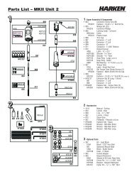
Parts List<br />
2 Wire assemblies including blocks and mast tangs<br />
1 62' (19 m) length of 5 /16" (8 mm) line with eye splice<br />
3 Stainless steel eyestraps<br />
1 Carbo cheek block<br />
1 4" (101 mm) aluminum cleat<br />
15 10-32 x 3 /8" (10 mm) truss head machine screws (includes 3 extra)<br />
15 3<br />
/16" (4.76 mm) stainless steel rivets (includes 3 extra)<br />
3 #10 x 1 1 /4" (32 mm) self-tapping screws (includes 1 extra)<br />
3 10-32 x 3 /4" (19 mm) trusshead machine screws (includes 1 extra)<br />
3 #10 x 3 /4" (19 mm) trusshead self-tapping screws (includes 1 extra)<br />
Tools Required<br />
Marker or pencil<br />
5<br />
/32" (4 mm) drill bit<br />
Center punch<br />
Phillips/slotted screwdriver<br />
Hammer<br />
Tape measure (long enough to measure luff length)<br />
Electric drill<br />
Pliers or vice grips<br />
Drill, Tap and Screw Method:<br />
1 – slotted screwdriver<br />
1 – 10-32 tap and handle<br />
1 – 5 /32" (4 mm) drill bit<br />
Rivet Gun Method: Stainless steel rivets require a heavy-duty rivet gun.<br />
It may be necessary to rent a rivet gun if you do not have a heavy-duty model.<br />
1 – 13 /64" (5 mm) drill bit<br />
Topping Lift<br />
To avoid snagging the mainsail on the <strong>Lazy</strong> <strong>Jack</strong>s when raising sail, the boat<br />
must be equipped with a topping lift or vang that holds boom lifted.<br />
Altering Sail Cover<br />
Take your sail cover to a sailmaker to have slits cut in the cover for the <strong>Lazy</strong> <strong>Jack</strong>s.<br />
Slits should have Velcro or snap closures to make it easy to cover the mainsail.<br />
Mark your cover after installation so the slots can be positioned correctly.<br />
Determining the Location of Mast Tang<br />
Measure the mainsail luff length or find the “P” dimension of the mast. Find this<br />
measurement in the left column below and circle the number in the right column.<br />
See drawing, page 3.<br />
Chart A<br />
The tang location Chart A<br />
The tang location<br />
If the mainsail luff length or measured from the If the mainsail luff length or measured from the<br />
“P” dimension measures: top of boom is: “P” dimension measures: top of boom is:<br />
31'7" to 32' 9.47 - 9.61 m 22'6" 6.85 m 37'1" to 37'6" 11.12 - 11.26 m 26'3" 8.00 m<br />
32'1" to 32’6" 9.62 - 9.76 m 22'9" 6.93 m 37'7" to 38' 11.27 - 11.41 m 26'7" 8.10 m<br />
32'7" to 33' 9.77 - 9.91 m 23'1" 7.03 m 38'1" to 38'6" 11.42 - 11.56 m 26'11" 8.20 m<br />
33'1" to 33'6" 9.92 - 10.06 m 23'5" 7.13 m 38'7" to 39' 11.57 - 11.71 m 27'4" 8.33 m<br />
33'7" to 34' 10.07 - 10.21 m 23'10" 7.26 m 39'7" 39'1" to 40' 39'6" 11.72 - 11.86 m 27'8" 8.43 m<br />
34'1" to 34'6" 10.22 - 10.36 m 24'2" 7.36 m 40'1" to 40'6" 11.87 - 12.01 m 28' 8.53 m<br />
34'7" to 35' 10.37 - 10.51 m 24'6" 7.46 m 40'1" to 40'6" 12.02 - 12.16 m 28'4" 8.63 m<br />
35'1" to 35'6" 10.52 - 10.66 m 24'10" 7.56 m 40'7" to 41' 12.17 - 12.31 m 28'8" 8.73 m<br />
35'7" to 36' 10.67 - 10.81 m 25'2" 7.66 m 41'1" to 41'6" 12.32 - 12.46 m 29'1" 8.86 m<br />
36'1" to 36'6" 10.82 - 10.96 m 25'7" 7.79 m 41'7" to 42' 12.47 - 12.60 m 29'5" 8.96 m<br />
36'7" to 37' 10.97 - 11.11 m 25'11" 7.89 m —<br />
— — —<br />
2
Installing Mast Tang and Wire Assembly<br />
If you are installing the system with the mast up, you will need to take up the following<br />
parts in the bosun's chair or send them up with a messenger line. (Follow all precautions<br />
to insure the safety of the person aloft. Make sure no one is standing where<br />
they could be hit with dropped tools.)<br />
WARNING! When drilling through mast, do not let drill bit contact the halyard that<br />
is holding you aloft! This may cause the halyard to fail. Limit depth.<br />
Tape measure<br />
Screw Method<br />
Port and starboard templates (attached to pg. 3) Drill with 5 /32" (4 mm) drill bit<br />
Tape for template<br />
#10-32 Tap and handle<br />
Tang assembly including wires and blocks Slotted screw driver<br />
Hammer<br />
Center punch<br />
10-32 x 3 /8" (10 mm) Trusshead<br />
machine screws<br />
Rivet Method<br />
Drill with 13 /64" (5 mm) drill bit<br />
Rivet gun and rivets<br />
Note: before going up the mast, insert the middle screw or rivet into the tang.<br />
Squeeze the top and bottom of the tang together to insert the screw or rivet. It<br />
may be necessary to use a pliers or vice grips.<br />
Measure up from the top of the boom to the height from chart A (page 2).<br />
Moveable Gooseneck - If the gooseneck is capable of moving up and down, measure<br />
from the top of the boom when the boom is positioned in its normal sailing position.<br />
Mark the mast at this point.<br />
Tape the template to the side of the mast so the middle hole is even with your mark.<br />
Line the template up so the vertical line is parallel to the side of the mast. See drawing<br />
below.<br />
Use a center punch to mark three tang holes. Remove template and drill three holes:<br />
Screws 5 /32" (4 mm) and Tap #10-32<br />
Rivets 13 /64" (5 mm).<br />
Attach tang starting from center hole.<br />
Installing Mast Tangs<br />
Mast Tang<br />
Assembly<br />
Top View<br />
Tangs installed<br />
on widest part<br />
of mast<br />
Measurement<br />
from<br />
Chart A<br />
3
Stringing the Control Lines<br />
Decide whether the adjusting block and cleat<br />
will be on port or starboard. The end of the line<br />
without the eye splice will be on the side of the<br />
boom where you will adjust the <strong>Lazy</strong> <strong>Jack</strong>s –<br />
the side where you will install the cleat.<br />
With the middle of the control line draped<br />
under the boom, pass the ends of the line<br />
up and run each end of the line through<br />
the blocks that are suspended from<br />
the wire. Run line through the<br />
blocks from stern to bow as<br />
shown in the diagram below.<br />
Eye Splice<br />
This will be adjusting side<br />
Determining the Location of Boom Hardware<br />
Measure the mainsail foot length or find the E dimension of the mast. Find<br />
this measurement in the left column below and circle the corresponding<br />
numbers in the right column. Put a mark on each side of the boom at<br />
each measurement. See drawing, page 5.<br />
Chart B – Location of Boom Hardware*<br />
“E” Dimension or Sail Foot Length<br />
8'7" to 9'<br />
2.57 - 2.71 m 1'11" (584 mm) 5'6" (1.676 m)<br />
9'1" to 9'6"<br />
2.72 - 2.86 m 2'1" (635 mm) 5'10" (1.778 m)<br />
9'7" to 10'<br />
2.87 - 3.01 m 2'2" (660 mm) 6'2" (1.880 m)<br />
10'1" to 10'6"<br />
3.02 - 3.16 m 2'3" (686 mm) 6'6" (1.981 m)<br />
10'7" to 11'<br />
3.17 - 3.31 m 2'4" (711 mm) 6'10" (2.083 m)<br />
11'1" to 11'6"<br />
3.32 - 3.46 m 2'6" (762 mm) 7'1" (2.159 m)<br />
11'7" to 12'<br />
3.47 - 3.61 m 2'7" (787 mm) 7'5" (2.261 m)<br />
12'1" to 12'6"<br />
3.62 - 3.76 m 2'8" (813 mm) 7'9" (2.362 m)<br />
12'7" to 13'<br />
3.77 - 3.91 m 2'10" (864 mm) 8'1" (2.464 m)<br />
13'1" to 13'6"<br />
3.92 - 4.06 m 2'11" (889 mm) 8'4" (2.540 m)<br />
13'7" to 14'<br />
4.07 - 4.21 m 3' ‐(914 mm) 8'8" (2.642 m)<br />
14'1" to 14'6"<br />
4.22 - 4.36 m 3'2" (965 mm) 9' ‐(2.743 m)<br />
14'7" to 15'<br />
4.37 - 4.51 m 3'3" (991 mm) 9'4" (2.845 m)<br />
15'1" to 15'6"<br />
4.52 - 4.66 m 3'4" (1.016 m) 9'8" (2.946 m)<br />
15'7" to 16'<br />
4.67 - 4.81 m 3'6" (1.067 m) 9'11" (3.023 m)<br />
*Note: You may want to check sail containment before drilling holes in the boom.<br />
To do this, put sail on, tape the boom hardware in place, reeve lines through system<br />
and lower sail. Move if necessary.<br />
4<br />
Cheek Block and<br />
Deadend Location<br />
Boom Cradle<br />
Strap Location
Installing Cheek Block<br />
Hold cheek block on the side of the boom so aft end of block is even with forward<br />
mark. Use cheek block as a template to mark holes and use center punch to start<br />
holes. Use 3 /4" (19 mm) long trusshead machine screws or self-tapping screws.<br />
Do not drill holes for rivets.<br />
DRILL HOLES: Machine Screws 5 /32" (4 mm) and Tap #10-32;<br />
Self-Tapping Screws 5 /32" (4 mm)<br />
Note: Position cheek block so sheave side of block is towards cleat. Refer to the two<br />
diagrams on page 6. In most cases cleat will be mounted forward of cheek block near<br />
forward end of boom. If there is other hardware in the way, mount cleat aft of block.<br />
Screw block to boom.<br />
Top View - Fittings Mounted to Side of Boom<br />
Sheave Side of Block is Towards Cleat<br />
Measurement from Chart B<br />
Installing Dead End Eyestrap<br />
Use the eyestrap as a template to mark holes and start holes using a center punch.<br />
DRILL HOLES: Screws 5 /32" (4 mm) and Tap #10-32 Rivets 13 /64" (5 mm)<br />
Important: Put eyestrap through line eye splice before fastening to mast.<br />
Use 3 /8" (10 mm) long screws or rivet eyestrap and line to boom.<br />
Mounting Adjusting Cleat<br />
Mount cleat near forward end of boom so <strong>Lazy</strong> <strong>Jack</strong>s may be easily adjusted. Before<br />
mounting cleat, swing boom out as far forward as it will go to make sure cleat does<br />
not hit mast. If you have a single line reefing or other obstruction forward of block,<br />
mount cleat aft of block as pictured on page 6. Use cleat as a template to mark holes<br />
and use center punch. Do not drill holes for rivets!<br />
Drill size for screws - 5 /32" (4 mm)<br />
Use supplied flat head self-tapping sheet metal screws.<br />
Note: If you have internal boom control lines, cut off the ends of the self tapping<br />
screws and round off tip to avoid snagging internal lines. First drive screws into<br />
boom to cut threads.<br />
5
Mounting Cradle Straps (Make sure you’ve checked sail containment before mounting eyestraps.)<br />
Pull aft line towards end of boom until line intersects with mark you have made as<br />
indicated in chart B. The eyestrap will be located aft of mark. See below.<br />
DRILL HOLES: Screws 5 /32" (4 mm) and Tap #10-32 Rivets 13 /64" (5 mm)<br />
Make sure line is inside eyestrap before riveting. Use 3 /8" (10 mm) long screws or<br />
rivet eyestrap in place.<br />
From Chart B<br />
Boom Cradle Strap Location From Chart B<br />
Alternate cleat location – sheave side of<br />
cheek block is towards cleat<br />
Using Shock Cord to Pull <strong>Lazy</strong> <strong>Jack</strong>s Outward<br />
We recommend shock cord to hold <strong>Lazy</strong> <strong>Jack</strong>s open to make it easier to raise sail.<br />
1. Attach shock cord to the end of the lower spreaders. Hog rings work well for this<br />
purpose. Use rigging tape over hog rings.<br />
2. Temporarily tie other end of shock cord to <strong>Lazy</strong> <strong>Jack</strong>s at a length that holds <strong>Lazy</strong><br />
<strong>Jack</strong>s out, yet will not be too short and damage spreaders when boom is swung out.<br />
3. Test length by swinging boom all the way out. If necessary, lengthen shock cord<br />
before permanently attaching to <strong>Lazy</strong> <strong>Jack</strong>s.<br />
Shock Cord<br />
6
Conventional Sail Slugs<br />
If using conventional sail slugs, make sure slugs are free to move below the gate.<br />
Use mast gate plates so sail slugs stay in the mast groove. Contact your rigger.<br />
Adjusting <strong>Lazy</strong> <strong>Jack</strong>s<br />
The <strong>Lazy</strong> <strong>Jack</strong> may be set to proper tension at dock. Raise mainsail and make sure<br />
adjusting line is uncleated at boom. Tighten mainsheet as tight as it will go to find<br />
maximum distance that boom will be lowered while under sail. Next tighten adjusting<br />
line and slack it off 2" (50 mm). The system should be set at a reasonable tension<br />
so it will not interfere with sail shape, yet will contain the sail when lowered onto<br />
the boom. Some further adjustment may be necessary.<br />
Using Your <strong>Lazy</strong> <strong>Jack</strong>s - Precautions<br />
Before sailing, make sure <strong>Lazy</strong> <strong>Jack</strong>s will not catch on spreaders. While at dock,<br />
swing boom out so sail is against spreader tips. Try lifting boom and shaking to see if<br />
<strong>Lazy</strong> <strong>Jack</strong> lines are apt to swing behind spreaders. When first sailing with <strong>Lazy</strong> <strong>Jack</strong>s,<br />
look aloft while sailing downwind to see if <strong>Lazy</strong> <strong>Jack</strong>s catch behind spreaders. If they<br />
get snagged while sailing, release snagged <strong>Lazy</strong> <strong>Jack</strong>s from behind spreader before<br />
bringing mainsail in towards center. If this is not done, you risk breaking spreaders<br />
as mainsheet is tensioned and mainsail moves toward the centerline.<br />
If <strong>Lazy</strong> jacks are prone to snagging spreader tips, there are 2 solutions. The easiest is<br />
to rig shock cords to pull <strong>Lazy</strong> <strong>Jack</strong>s forward out of way of spreader tips. Rig a length<br />
of shock cord on each side of sail. Dead end shock cord at or near gooseneck and<br />
run it up to blocks which are suspended from wires.<br />
If this does not help, you will need to reposition Mast Tangs so they are lower on<br />
mast and do not interfere with spreader tips.<br />
Raising Sail<br />
When hoisting sail, check to make sure the sail does not get caught in the <strong>Lazy</strong> <strong>Jack</strong>s.<br />
The headboard or battens may catch between the mast and the <strong>Lazy</strong> <strong>Jack</strong>s or jam in<br />
the angle between the lines. If the halyard is forced, this could result in a broken batten,<br />
ripped sail or damaged <strong>Lazy</strong> <strong>Jack</strong>. To avoid this, look aloft as you raise the mainsail<br />
and stop if the sail gets caught. Also, make sure the boat is facing head-to-wind.<br />
The sail is less apt to catch on the <strong>Lazy</strong> <strong>Jack</strong>s if the topping lift is used and the <strong>Lazy</strong><br />
<strong>Jack</strong>s are somewhat loose. This way they will deflect out of the way easier when the<br />
sail makes contact with them.<br />
7
Corporate Headquarters<br />
N15W24983 Bluemound Rd, Pewaukee, WI 53072 USA<br />
Telephone: (262) 691-3320 • Fax: (262) 701-5780<br />
Web: www.harken.com • Online Catalog: www.harkenstore.com<br />
Email: harken@harken.com<br />
<strong>Harken</strong> Australia Pty, Ltd.<br />
1B Green Street, Brookvale, N.S.W. 2100, Australia<br />
Telephone: (61) 2-8978-8666 • Fax: (61) 2-8978-8667<br />
Web: harken.com.au • Email: info@harken.com.au<br />
<strong>Harken</strong> France<br />
ZA Port des Minimes, BP 3064, 17032 La Rochelle Cedex 1, France<br />
Telephone: (33) 05.46.44.51.20 • Fax: (33) 05.46.44.25.70<br />
Web: harken.fr • Email: info@harken.fr<br />
<strong>Harken</strong> Italy S.p.A.<br />
Via Marco Biagi, 14, 22070 Limido Comasco (CO) Italy<br />
Telephone: (39) 031.3523511 • Fax: (39) 031.3520031<br />
Web: harken.it • Email: info@harken.it<br />
<strong>Harken</strong> New Zealand, Ltd.<br />
30-36 Fanshawe Street, P.O. Box 1951, Auckland 1001, New Zealand<br />
Telephone: (64) 9-303-3744 • Fax: (64) 9-307-7987<br />
Web: harken.co.nz • Email: harken@harken.co.nz<br />
<strong>Harken</strong> Polska SP ZOO<br />
ul. Rydygiera 8, budynek 3A, lokal 101, I piętro, 01-793 Warszawa, Poland<br />
Tel: +48 22 561 93 93 • Fax: +48 22 839 22 75<br />
Web: harken.pl • Email: polska@harken.pl<br />
<strong>Harken</strong> Sweden AB<br />
Main Office and <strong>Harken</strong> Brandstore: Västmannagatan 81B<br />
SE-113 26 Stockholm Sweden<br />
Telephone: (46) 0303 61875 • Fax: (46) 0303 61876<br />
Mailing address: <strong>Harken</strong> Sweden AB, Box 64, SE -440 30 Marstrand<br />
Web: harken.se • Email: harken@harken.se<br />
<strong>Harken</strong> UK, Ltd.<br />
Bearing House, Ampress Lane, Lymington, Hampshire S041 8LW, England<br />
Telephone: (44) 01590-689122 • Fax: (44) 01590-610274<br />
Web: harken.co.uk • Email: enquiries@harken.co.uk<br />
Please visit: http://www.harken.com/locator.aspx<br />
to locate <strong>Harken</strong> dealers and distributors<br />
Printed in USA 4059 12/13