You also want an ePaper? Increase the reach of your titles
YUMPU automatically turns print PDFs into web optimized ePapers that Google loves.
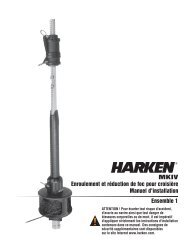
Hydraulic Furling Installation Manual – <strong>Unit</strong> 4.5
GENERAL SPECIFICATIONS<br />
■ TABLE OF CONTENTS<br />
General Specifications<br />
2 Table of Contents, Dimensions<br />
3 Stainless Surface, Hoses & Fittings<br />
4 Drain System, Valves, Pressure, Oil<br />
5 Part List<br />
Preparation<br />
7 Headstay Length, Connectors<br />
8 Foil Length<br />
9 Connector and Foil Quantity<br />
Assembly<br />
10 Foil Assembly<br />
12 Stay to Lower <strong>Unit</strong> Connection<br />
14 Lower Toggle and Cowling<br />
15 Torque Tube Alignment<br />
16 Foil Length Check<br />
17 Raise <strong>Unit</strong>; Gear Box Pressure<br />
18 Hoses, Oil Level<br />
19 Headstay Tension<br />
20 Halyard Wraps<br />
21 Pendants<br />
22 Halyard Restrainer<br />
23 Before Operation<br />
Table of Contents<br />
A B C D E<br />
48 5 /8”<br />
1235 mm<br />
32 1 /2”<br />
826 mm<br />
28 1 /4”<br />
718 mm<br />
14 7 /8”<br />
378 mm<br />
15 7 /8”<br />
403 mm<br />
F G H I J<br />
17 7 /8”<br />
454 mm<br />
DIMENSIONS - *<strong>Unit</strong> with 1 3 /8” (34.9 mm) clevis<br />
8 1 /2”<br />
216 mm<br />
9 5 /8”<br />
244 mm<br />
14”<br />
356 mm<br />
18 1 /8”<br />
460 mm<br />
*Subtract 5 /16” (8 mm) for 1 1 /4” (31.8 mm) clevis. Add 5 /8” (16 mm)<br />
for 1 9 /16” (39.7 mm) clevis (A to F only).<br />
HARKEN - Main Office<br />
1251 E. Wisconsin Avenue, Pewaukee WI 53072<br />
Tel: 262-691-3320, Fax: 262-691-3008<br />
HARKEN - East (Trade Only)<br />
One Mill Street, Newport RI 02840<br />
Tel: 401-849-8278, Fax: 401-841-5070<br />
HARKEN - West (Trade Only)<br />
Tel: 619-475-0712, Fax: 619-475-0816<br />
2 Hydraulic Furling 4.5 December 2002
GENERAL SPECIFICATIONS <strong>Unit</strong> 4.5<br />
■ STAINLESS STEEL SURFACE<br />
Be careful not to scratch the stainless steel surfaces of the<br />
lower unit. Lay the unit on terry cloth or other soft material<br />
while assembling.<br />
The hydraulic unit is polished stainless and does not have<br />
chrome plating. (Chrome was eliminated due to occasional<br />
discoloration.) This surface can be polished using standard<br />
stainless steel polishes to maintain its appearance.<br />
■ PORT SIDE UP<br />
Keep the port side of the unit facing up when sitting on its<br />
side.<br />
If the unit will sit for a long period of time, or is stored or<br />
shipped, keep the port side of the lower unit facing up. This<br />
will prevent gear oil from leaking out of a pressure relief<br />
valve.<br />
TIP: When the port side is up, the sideplate with the winch<br />
handle socket will be facing down.<br />
If a small amount of gear oil does leak out of the valve during<br />
shipping or installation, it will drip out of the bottom of the<br />
unit when up in sailing position. Use a rag to catch this<br />
leakage.<br />
■ HOSES<br />
Hoses are not supplied with furler.<br />
Use SAE 100 R1 or R2 hoses.<br />
Sizes depend on the distance that the hoses will run and<br />
the power source. For shorter runs use:<br />
Two Drive Hoses: -6 ( 3 /8” ID)<br />
One Drain Hose: -4 (1 /4” ID)<br />
Contact <strong>Harken</strong> for further hose size recommendations.<br />
■ HOSE END FITTINGS<br />
Hose fittings are not supplied with furler.<br />
All fittings must be stainless steel. Standard attachment<br />
method uses female hose end fittings.<br />
Furling unit end fittings have JIC 37° flair fittings.<br />
Note: Do not use locking solution or tape on connections.<br />
Hose end fittings sizes:<br />
Drive fittings - JIC 9/16-18 female swivel<br />
Drain fittings - JIC 7/16-20 female swivel<br />
■ ALTERNATE FITTING METHOD<br />
Remove furling unit end fittings. Use SAE straight thread<br />
O-ring male hose end fittings:<br />
Drive fitting - 9/16-18<br />
Drain fitting - 7/16-20<br />
April 2000 Hydraulic Furling 4.5 3
GENERAL SPECIFICATIONS <strong>Unit</strong> 4.5<br />
■ DRAIN SYSTEM<br />
Besides the main hoses for forward and reverse, a fitting for<br />
a drain hose is included. The drain hose must be lead to the<br />
main reservoir in the power unit.<br />
Power Requirements<br />
Size<br />
4.5<br />
Recommended Flow Rate<br />
7 GPM (26.7 L/min.)<br />
Rotation at No Load<br />
32 RPM<br />
The unit will work with any <strong>Harken</strong> hydraulic power pack.<br />
Best performance will be with the hydraulic 6 or 8 system.<br />
See performance charts.<br />
■ Valves On Power <strong>Unit</strong><br />
Furler can be used with open or closed center, 4-way,<br />
3-position control valves.<br />
■ MAXIMUM OPERATION PRESSURE<br />
Set relief valve on power plant at 140 Bar or 2000 PSI.<br />
<strong>Harken</strong> power packs ship with valves set at 140 Bar.<br />
■ OIL SPECIFICATIONS<br />
Gear box oil - AGMA8, 90 weight gear oil<br />
24 ounce (680 g) capacity<br />
Note: The gear box is filled with oil at the factory.<br />
Under normal conditions there is no need to change<br />
the gear box oil.<br />
Hydraulic fluid is a petroleum based oil, ISO viscosity<br />
grade 46, anti-corrosion, anti-foam, anti-oxidant, anti-rust,<br />
anti-wear additives.<br />
Fluid examples: Exxon Nuto, Shell Tellus, BP Energol HLP<br />
WARNING: The only parts of the furler to be disassembled by<br />
the installer are: Torque Tube, Lower Cowling. All other work<br />
should be performed by factory authorized personnel.<br />
Note: Some fluid may drip from the unit during shipping.<br />
This is normal and should go away once the unit is in its<br />
sailing position. All units are tested before leaving the factory.<br />
<strong>Unit</strong>s are shipped port side facing up.<br />
Make sure unit is shipped or stored port side up.<br />
If it’s not, gear oil will leak out of the pressure relief valve.<br />
4 Hydraulic Furling 4.5 April 2000
GENERAL SPECIFICATIONS<br />
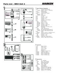
Parts List<br />
■ MAIN COMPONENTS<br />
Halyard Swivel<br />
Cowling<br />
Torque Tube<br />
Toggle<br />
■ MAIN HOUSING<br />
April 2000 Hydraulic Furling 4.5 5
GENERAL SPECIFICATIONS<br />
Parts List<br />
■ MISCELLANEOUS PARTS<br />
Red Loctite Foil Screws Foil Wedges<br />
Blue Loctite Torque Tube 6mm, 8mm<br />
Screws<br />
Allen Wrench<br />
Cross Pin Clevis Pin Cotter Pin<br />
Circlip Tack Shackle Feeder<br />
■ RIGGER PARTS<br />
Trim Cap Connectors Long Bottom<br />
Connector<br />
■ TERMINAL-WIRE<br />
Nosepiece<br />
Main Body<br />
Wedge<br />
Former<br />
Drive Pin<br />
■ TERMINAL-ROD<br />
Nosepiece Drive Pin Collar<br />
■ FOILS<br />
Bottom Foil<br />
Foils<br />
6 Hydraulic Furling 4.5 April 2000
PREPARATION<br />
Headstay Length<br />
■ HEADSTAY CUT LENGTH<br />
The following cut lengths will result in the headstay adjuster<br />
being 1 /2 open. At this cut length, 3 1 /2” (89 mm) of adjustment<br />
will remain in the stay adjuster in either direction.<br />
Subtract the following from the headstay length and cut the<br />
stay at that point.<br />
Headstay<br />
Size<br />
-76 (17.9 mm rod) 31 7 /8” (810 mm)<br />
HEADSTAY CUT LENGTH CHART<br />
Clevis Pin Size<br />
1 1 /4” (31.80 mm) 1 3 /8” (34.90 mm) 1 9 /16” (39.70 mm)<br />
-91 (19.5 mm rod) 31 7 /8” (810 mm) 32 1 /4” (819 mm)<br />
-115 (22.2mm rod) 32 3 /8” (822 mm)<br />
25 mm wire 32 7 /8” (835 mm) 33 3 /8” (848 mm) 33 7 /8” (860 mm)<br />
Note: The <strong>Harken</strong> hydraulic furler has an integral toggle. No<br />
additional toggle is required below the furler.<br />
Contact <strong>Harken</strong> to coordinate position of headstay rod splices<br />
with connector location.<br />
■ STRINGING CONNECTORS ON STAY<br />
Make sure the trim cap is at the top and the correct number<br />
of connectors are used. The long bottom connector must be<br />
slid on the wire or rod so the feeder holes will be matched to<br />
the window in the foil.<br />
Make sure the “up” arrow stamped on the front of the<br />
connector is pointing to the top of the stay.<br />
Up<br />
Arrow<br />
■ ROD COLDHEAD HEIGHT<br />
Make sure the length of rod coldhead does not interfere with<br />
the drive pin. There is a .40” (10 mm) space between the collet<br />
bottom and the roll pin.<br />
April 2000 Hydraulic Furling 4.5 7
PREPARATION<br />
Foil Length<br />
■ FOIL CUT LENGTH - UNIT 4.5<br />
Foil cut length is based on pin-to-pin length as measured<br />
from center of upper pin (attaches the stay to the mast) to<br />
center of lower pin (attaches the furling unit to the boat).<br />
Measurement includes the masthead toggle. The hydraulic<br />
furler has a lower integral toggle. No additional toggle is<br />
required below the unit.<br />
There must be more than 3 1 /2” (89 mm) of adjustment above<br />
the trim cap when the adjuster is set to the half way point.<br />
The total adjuster stroke is 7” (178 mm). (See inset 1)<br />
To check foil length, lay foils alongside stay before cutting<br />
top foil. Set stay adjuster to the half way point.<br />
■ TOP FOIL CUT LENGTH<br />
Instructions For Worksheet Below:<br />
1 Fill in total pin-to-pin length. Fill in A length.<br />
2 Fill in F from numbers below:<br />
1 1 /4” (31.8 mm) Clevis pin = 43” (1092 mm)<br />
1 3 /8” (34.9 mm) Clevis pin = 43 1 /4” (1099 mm)<br />
1 9 /16” (39.7 mm) Clevis pin = 44” (1118 mm)<br />
3 Add A, B, E, F and subtract from total pin-to-pin length. SUM = _______<br />
4 Choose the number from foil multiplier below closest to<br />
but not greater than, sum from step 3. Fill in D length.<br />
*5 x 144 = 720 **5 x 3657.5 = 18288<br />
6 x 144 = 864 6 x 3657.5 = 21945<br />
7 x 144 = 1008 7 x 3657.5 = 25603<br />
8 x 144 = 1152 8 x 3657.5 = 29260<br />
9 x 144 = 1296 9 x 3657.5 = 32918<br />
10 x 144 = 1440 10 x 3657.5 = 36575<br />
5 Add A, B, D, E, F.<br />
Subtract from pin-to-pin length for C (top foil length).<br />
WORKSHEET: DETERMINE TOP FOIL LENGTH<br />
DIMENSIONS INCHES MM<br />
A Center of PIN to Bottom of Terminal _____ _____<br />
B Bottom of Terminal to Top of Foil 6 152<br />
C Top Foil _____ _____<br />
D __?__ 144” (3657.5 mm) Foils *_____ **____<br />
(Quantity)<br />
E Bottom Foil 24 610<br />
F Clevis Pin to Foil _____<br />
_____<br />
Total Pin-to-Pin Length _____ _____<br />
BEFORE CUTTING: If top foil is less than 19 5 /8” (498 mm),<br />
shorten top trim cap bushing. If this will not work, it may be<br />
necessary to shorten one of the full length foils and redrill<br />
holes.<br />
Drill a 17 /32” (13.2 mm) trim cap hole in the top foil, opposite the<br />
grooves, centered at 4” (101.5 mm) from the top of the foil.<br />
8 Hydraulic Furling 4.5 April 2000
PREPARATION<br />
Cutting Top Foil<br />
■ NOTES<br />
<strong>Unit</strong> 4.5 foils are 12’ (3.658 m) long. <strong>Unit</strong> 4.5 has no feeder<br />
gap.<br />
There must be at least 3 1 /2” (89 mm) of wire above the trim<br />
cap when the adjuster is set to the half way point. The total<br />
adjuster stroke is 7” (178 mm). Drill a 17 /32” (13.2 mm) trim<br />
cap hole in the top foil, opposite the grooves, centered at 4”<br />
(101.5 mm) from the top of the foil.<br />
■ CONNECTOR & FOIL QUANTITY<br />
Refer to the Top Foil Length Worksheet.<br />
<strong>Unit</strong> 4.5 requires one fewer regular connector than number<br />
of foils. (Count top foil, but not bottom foil.) In addition,<br />
a trim cap and long bottom connector is required.<br />
■ CUTTING TOP FOIL<br />
Once you have checked the top foil length, cut the top foil.<br />
Deburr and clean all shavings from the foil.<br />
Important: Failure to deburr or clean the inside of the foil<br />
may cause it to seize to a connector when installing on rod.<br />
April 2000 Hydraulic Furling 4.5 9
ASSEMBLY<br />
Foils<br />
■ ASSEMBLE FOIL<br />
Make sure you have drilled a hole in the top foil so it lines<br />
up with the hole tapped in the trim cap.<br />
Slide top foil to top of stay, screw holes towards the bottom.<br />
TIP: When working with rod, tape lower connectors in place or<br />
use a pusher wire longer than foil to hold connectors.<br />
Coat the trim cap top bushing with red Loctite.<br />
Place a wedge in the indentation and insert into the top foil.<br />
Coat a foil screw with red Loctite. Thread into connector<br />
hole.<br />
Slide first connector to the top of the stay. Coat half<br />
of the connector and the indentation with red Loctite.<br />
Place a plastic connector wedge in the indentation<br />
closest to the top foil.<br />
10 Hydraulic Furling 4.5 April 2000
ASSEMBLY<br />
Foils<br />
Coat three foil screws with red Loctite.<br />
Screw them into the connector until tight.<br />
Continue assembly.<br />
Slide halyard swivel onto foil, tall end up.<br />
Install feeder screws toward bottom, using red Loctite on<br />
screws.<br />
Slide torque tube onto foils.<br />
April 2000 Hydraulic Furling 4.5 11
ASSEMBLY<br />
Attach Stay - Rod<br />
■ ATTACHING STAY TO LOWER UNIT - ROD<br />
Use a winch handle to crank the terminal completely out of<br />
the lower unit.<br />
Make sure halyard swivel and torque tube have been slipped<br />
on the foils.<br />
Slip the rod adapter main body onto the rod.<br />
Sandwich the nosepiece over the rod and insert into the main<br />
body, narrow end first. Jiggle the main body or use a small<br />
screwdriver to push the nosepiece completely into main<br />
body.<br />
Put several drops of the blue Loctite on the large threads of<br />
the stud. Thread the stud into the main body until the slot<br />
aligns neatly with the hole in the main body.<br />
TIP: Sight through the pin hole to find the optimum thread<br />
engagement. Make sure the stud is threaded far<br />
enough so the pin is securely seated in the slot, yet<br />
not threaded too far to block the pin.<br />
Hammer the pin into the main body. Put blue Loctite on pin.<br />
Clean excess Loctite from the terminal body using special<br />
care to insure that no Loctite is present on the lower<br />
threaded stud.<br />
12 Hydraulic Furling 4.5 April 2000
ASSEMBLY<br />
Attach Stay - Wire<br />
■ ATTACHING STAY TO LOWER UNIT — WIRE<br />
Assemble wire terminal per Sta-lok instructions.<br />
Note: To prevent seizing nosepiece threads when forming<br />
the wires, put red Loctite on the threads to lubricate them.<br />
Open terminal up for inspection. Put sealant inside terminal.<br />
Use a winch handle to crank the terminal completely out of<br />
the lower unit.<br />
Apply red Loctite to the stud or the socket of wire terminal.<br />
Clean excess Loctite off the stud below the terminal.<br />
Thread the hydraulic unit onto the Sta-Lok terminal and wire.<br />
Protect stainless steel housing and sideplates from scratching<br />
when rotating unit. Use saw horses that are padded and have<br />
terry cloth covering.<br />
Put red Loctite on the pin and drive it into place.<br />
Clean excess Loctite from the terminal body using special<br />
care to insure that no Loctite is present on the lower<br />
threaded stud.<br />
April 2000 Hydraulic Furling 4.5 13
ASSEMBLY<br />
Lower Toggle and Cowling<br />
■ INSTALL LOWER TOGGLE AND COWLING<br />
The integral toggle can be installed so the clevis pin runs<br />
either fore/aft or athwartships.<br />
Choose the correct hole in the base and use the cross pin to<br />
secure the lower toggle so clevis pin runs the correct direction.<br />
Slip the cowling in place.<br />
Secure using the circlip provided.<br />
14 Hydraulic Furling 4.5 April 2000
ASSEMBLY<br />
Torque Tube<br />
■ INSTALL TORQUE TUBE<br />
Secure the torque tube to the lower unit using the six cap<br />
screws provided. Use blue Loctite on the screws.<br />
TIP: Insert all six screws BEFORE tightening.<br />
■ RAISE FOILS<br />
Push the foils to the correct height and use an allen wrench<br />
to secure the torque tube to the foils using the three screws<br />
provided.<br />
Use blue Loctite on the screws.<br />
April 2000 Hydraulic Furling 4.5 15
ASSEMBLY<br />
Foil Length<br />
■ CHECK FOIL LENGTH<br />
Once the foils and lower unit are assembled, use a winch<br />
handle to close the stay adjuster. Turn the handle in a<br />
clockwise direction.<br />
Check the clearance between the top of the foil and top terminal.<br />
TIP: Check clearance when the unit is on the ground,<br />
before raising the headstay into position.<br />
WARNING: It is critical to have clearance between the top<br />
foil and the top rigging fitting when the stay adjuster is in the<br />
fully closed position. If the fittings touch, the unit will jam<br />
or in the case of a Sta-Lok fitting, the terminal may become<br />
unscrewed. This could cause catastrophic failure to the spar<br />
and a life threatening situation.<br />
It is the responsibility of the rigger to check clearance.<br />
16 Hydraulic Furling 4.5 April 2000
ASSEMBLY<br />
Raise Furling • Gearbox Pressure<br />
■ RAISE FURLING UNIT ON MAST<br />
CAUTION: To prevent damage to the stay adjuster, make sure<br />
the torque tube is secured to the foils and the lower unit<br />
before moving the unit.<br />
If the unit will sit for a long time, make sure the port side of<br />
the lower unit is facing up.<br />
TIP: The sideplate with the winch handle socket will be<br />
facing down.<br />
Once you have closed the stay adjuster to confirm there<br />
is clearance above the foils, open the adjuster all the way.<br />
Turn the stay adjuster counter-clockwise to open the adjuster<br />
completely. This makes it easier to connect the stay to the<br />
boat.<br />
TIP: Cover unit with terry cloth & padding to protect<br />
stainless finish.<br />
■ GEARBOX PRESSURE<br />
It is possible that pressure has built up in the gear box<br />
during shipping.<br />
Once the unit is in sailing position, relieve pressure by using<br />
a 6 mm allen wrench to open the filler valve on top of the<br />
lower unit.<br />
Install the cap so it is wrist tight (20 foot pounds).<br />
April 2000 Hydraulic Furling 4.5 17
ASSEMBLY<br />
Hoses<br />
■ INSTALL HOSES<br />
Use hose end fittings which are:<br />
Drive: JIC 9/16-18 female swivel<br />
Drain: JIC 7/16-20 female swivel<br />
Do not use locking solution or tape on connections.<br />
Alternate Method: Remove furling unit end fittings and<br />
use SAE straight thread O-ring male hose end fittings.<br />
■ CHECK GEAR OIL LEVEL<br />
WARNING: Do not overfill gear oil. Overfilling will cause<br />
leaking from the breather valve.<br />
Oil can be checked from the top of the case. Insert a small<br />
metal stick into the filler hole at the top of the gear housing.<br />
Oil should be at the bottom of the gears. When the unit is in<br />
the angled sailing position, the oil level will be 2” (51 mm)<br />
from the top of the housing.<br />
18 Hydraulic Furling 4.5 April 2000
ADJUSTMENTS<br />
Headstay Tension<br />
■ ADJUST HEADSTAY TENSION<br />
There is no need to unlock the turnbuckle. If the sail is up,<br />
make sure the halyard is loose.<br />
Do not adjust under sail.<br />
Insert a winch handle and rotate counter clockwise to<br />
loosen or clockwise to tighten the stay. Total adjustment is<br />
7” (178 mm).<br />
CAUTION: When tightening the stay, if the handle becomes<br />
suddenly hard, stop immediately. Forcing the handle when<br />
the adjuster is completely closed will damage the gears.<br />
All final rig tensioning or spar bending should be done<br />
using a conventional backstay adjuster.<br />
April 2000 Hydraulic Furling 4.5 19
ADJUSTMENTS<br />
Halyard Wraps<br />
■ HALYARD WRAPS<br />
The most serious problem with furling systems occurs when<br />
the jib halyard wraps around the headstay foil. Halyard wraps<br />
will prevent furling or unfurling and may cause serious damage<br />
to the unit and the halyard. In severe cases, halyard wraps<br />
may cause loss of the headstay.<br />
To prevent wraps, the halyard must exert a slight pull to<br />
the rear. This allows the foils to turn while the halyard<br />
remains stationary.<br />
■ PREVENT WRAPS<br />
WARNING: The sail must be fitted to the foils before operation.<br />
1 Halyard swivel should be within the top 6” (150 mm)<br />
of the foil.<br />
2 Halyard must pull slightly to the rear (8 - 10°).<br />
3 Halyard must be snug, but not too tight.<br />
TIP: With the sail raised, walk away from the boat and look<br />
at the masthead with binoculars. Use the halyard<br />
swivel as a measurement reference. 6” (150 mm) is<br />
1<br />
/3 the length of the swivel. There should be less foil<br />
exposed above the swivel than 1 /3 of the swivel.<br />
8 - 10°<br />
If a halyard wraps, do not force the unit to turn. Attempt to<br />
open the sail by alternately furling in and out slightly.<br />
If the sail can be unfurled, lower the sail by releasing the jib<br />
halyard. Severe halyard wraps can only be cleared by going<br />
aloft and freeing the halyard.<br />
If the sail will not furl or unfurl, it may be possible to remove<br />
the jib sheets and manually wrap the sail around the headstay.<br />
Remember: Testing at the dock does not indicate the halyard<br />
angle is correct. In wave action, the foils may wrap if the lead<br />
angle is not correct. The diverging 8-10°angle mentioned<br />
above is critical.<br />
20 Hydraulic Furling 4.5 April 2000
ADJUSTMENTS<br />
Pendants<br />
■ PENDANTS<br />
If your sail is not long enough to position the halyard swivel<br />
properly, you must add a pendant to the sail. Pendants<br />
should be plastic coated wire permanently attached to the<br />
sail so the height will be correct. Adjustable length pendants<br />
are not acceptable as they might not be adjusted correctly<br />
during a sail change.<br />
■ INSTALL A PENDANT<br />
1 Raise the sail, but do not attach tack shackle.<br />
2 Position the halyard swivel correctly near the top of the<br />
headstay and secure the halyard.<br />
3 Secure a piece of rope to the sail tack. Lead the line<br />
through the tack shackle on the furling drum and<br />
tension the sail.<br />
4 Measure the distance from the tack shackle to the sail tack<br />
and have a pendant of this length permanently attached to<br />
the head of the sail.<br />
5 Repeat this procedure for every jib.<br />
TIP: Pendants are used at the head of the sail. Short pendants<br />
may be added at the tack to improve visibility under<br />
the genoa, but remember that visibility is already<br />
improved by shackling to the tack swivel.<br />
Tack pendants increase heeling moment by raising<br />
the sail plan. You may install pendants at both the<br />
head and tack of the sail.<br />
April 2000 Hydraulic Furling 4.5 21
ADJUSTMENTS<br />
■ HALYARD RESTRAINER<br />
To prevent wraps, the jib halyard must pull slight to the rear.<br />
On some boats the halyard sheaves are located too close<br />
to the headstay and a halyard restrainer must be used.<br />
Use halyard restrainers only when required by the masthead<br />
geometry. Restrainers tend to limit sail luff length and may<br />
cause problems if not properly installed.<br />
Mount the restrainer as high as possible on the face of the<br />
mast. Position the restrainer so the foils will not hit it when<br />
under load.<br />
The restrainer should deflect the halyard 8-10°. If the angle<br />
is more than 10°, you may experience difficulty in tensioning<br />
the sail luff, friction in furling and possible damage to the<br />
foils. To decrease deflection angles, shorten the luff of the<br />
sail.<br />
Halyard Restrainer • Tension<br />
8 - 10°<br />
TIP: Boats used in charter service should consider using a<br />
halyard restrainer, regardless of masthead geometry.<br />
■ HALYARD TENSION<br />
The jib halyard should be firm, but not too tight.<br />
TIP: The luff foil system supports the sail along its entire<br />
length so halyard tension is required only to shape<br />
sails, not to support them.<br />
Use only enough halyard tension to remove some<br />
wrinkles along the luff. Do not tension the halyard<br />
enough to cause vertical wrinkles in the luff.<br />
Use halyard tension to adjust draft position of the sail<br />
to suit sailing conditions. Your halyard should be<br />
firm but not tight. If in doubt, release halyard tension.<br />
To protect the sail, ease the halyard when the boat is<br />
not in use.<br />
22 Hydraulic Furling 4.5 April 2000
ADJUSTMENTS<br />
Before Operation • Manual Operation<br />
■ BEFORE OPERATION<br />
WARNING: Before operating, consult pages on halyard lead<br />
angle. If sails are changed, make sure halyard lead angle is<br />
correct. A halyard wrap cannot be tolerated on a hydraulic<br />
furler.<br />
Make sure to ease sheets before operating the system.<br />
CAUTION: Do not use the hydraulic furler to sheet the sail.<br />
The direction of furling is up to the individual. Make sure<br />
suncover is rolled correctly.<br />
TIP: Label the buttons “in” and “out” and be consistent in<br />
their use when rolling and unrolling the sail. This way,<br />
it will be possible to furl in the desired direction at<br />
night when the sail is hard to see.<br />
■ MANUAL OPERATION<br />
To furl or unfurl the unit manually, push the lever to manual<br />
and insert a winch handle in the starboard socket. Rotate to<br />
move the sail in or out.<br />
April 2000 Hydraulic Furling 4.5 23
Corporate Headquarters<br />
1251 East Wisconsin Avenue, Pewaukee, Wisconsin 53072 USA<br />
Telephone: (262) 691-3320 • Fax: (262) 691-3008 • Cable: <strong>Harken</strong> Pewaukee<br />
Web: www.harken.com • Online Catalog: www.harkenstore.com<br />
Email: harken@harken.com<br />
<strong>Harken</strong> France<br />
ZA. Port des Minimes, BP 3064, 17032 - La Rochelle Cedex 1, France<br />
Telephone: (33) 05.46.44.51.20 • Fax: (33) 05.46.44.25.70<br />
Web: www.harken.fr<br />
Email: harken@harken.fr<br />
<strong>Harken</strong> Italy S.P.A.<br />
Via Della Cerca, 12/14, 22070 Lurago Marinone, Como, Italy<br />
Telephone: (39) 031.3523511 • Fax: (39) 031.3520031<br />
Web: www.harken.it<br />
Email: info@harken.it<br />
<strong>Harken</strong> UK Ltd.<br />
Bearing House, Ampress Lane<br />
Lymington, Hampshire S041 8LW, England<br />
Telephone: (44) 01590-689122 • Fax: (44) 01590-610274<br />
Web: www.harken.co.uk<br />
Email: enquiries@harken.co.uk<br />
<strong>Harken</strong> Poland<br />
ul. Lisa Kuli 4 lok.1, 01-512 Warszawa, Polska<br />
Telephone: 022 561 93 93 • Fax: 022 839 22 75<br />
Web: www.harken.com<br />
Email: polska@harken.com<br />
<strong>Harken</strong> Sweden<br />
Mjölkekilsgatan 6, Box 64<br />
S-440 30 Marstrand, Sweden<br />
Telephone: (46) 303-618 75 • Fax: (46) 303-618 76<br />
Web: www.harken.se<br />
Email: harken@harken.se<br />
<strong>Harken</strong> Adriatik d.o.o.<br />
Obala 107<br />
6320 Portoroz, Slovenia<br />
Telephone/Fax: 5-6774122<br />
Web: www.harken.si<br />
Email: info@harken.si<br />
<strong>Harken</strong> Australia, Pty, Ltd.<br />
1B Green Street<br />
Brookvale, N.S.W. 2100, Australia<br />
Telephone: (61) 2-8978-8666 • Fax: (61) 2-8978-8667<br />
Web: www.harken.com.au<br />
Email: info.harken.com.au<br />
<strong>Harken</strong> New Zealand, Ltd.<br />
30-36 Fanshawe Street<br />
Auckland 1001, New Zealand<br />
Telephone: (64) 9-303-3744 • Fax: (64) 9-307-7987<br />
Web: www.harken.co.nz<br />
Email: harken@harken.co.nz<br />
Please visit: http://www.harken.com/dealers/dealers.php<br />
for an up-to-date list of <strong>Harken</strong> dealers and distributors<br />
Printed in USA 4905/11-06