Phillips - H. A. Phillips & Co.
Phillips - H. A. Phillips & Co.
Phillips - H. A. Phillips & Co.

Create successful ePaper yourself
Turn your PDF publications into a flip-book with our unique Google optimized e-Paper software.
<strong>Phillips</strong> ®<br />
REFRIGERATION<br />
VALVES • VESSELS • SYSTEMS • CONTROLS<br />
LOW SIDE VALVES<br />
Series 701S<br />
BULLETIN 701S-06E-01<br />
Engineering Data<br />
Features<br />
• Pressure Rating: 300PSI (-20ºF – +240ºF)<br />
• ASTM A536 Gr. 65-45-12 Ductile Iron<br />
Body and Bonnet<br />
• Modulating Level through Metering Pilot<br />
• Normally Closed<br />
• Manual Lifting Stem<br />
• Strainer Available<br />
• Teflon Seat Disks are Replaceable<br />
PILOT OPERATED<br />
FIXED OR ADJUSTABLE LEVEL<br />
Size: 1/2”- 4”<br />
For Ammonia (R-717) and Halocarbon Refrigerants<br />
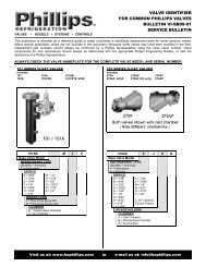
Description<br />
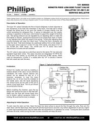
The <strong>Phillips</strong>® Series 701S Low Side valves are pilotoperated<br />
piston-type valves which meter the flow of<br />
liquid refrigerant to an evaporator or pressure vessel<br />
in response to liquid level requirements. The 701S is<br />
controlled by a float valve which responds to changing<br />
requirements, providing a modulating control<br />
arrangement.<br />
The 701S valves are flanged and may be supplied with<br />
a mating strainer. A metering plug and spring are selected<br />
for specific operating conditions. A manual opening<br />
stem, for raising the metering plug off the internal port,<br />
and a replaceable PTFE seat disc are standard.<br />
In fixed level applications, the 701S is typically controlled<br />
by a 301E float valve. The 301E is mounted in a<br />
welded steel chamber, external to the vessel where the<br />
level is being controlled. The chamber is equipped with<br />
a <strong>Phillips</strong>® Level Eye® for visual indication of the liquid<br />
level. See Bulletin 301E. (A Series 300 float valve, which<br />
mounts internal to the vessel being controlled, will also<br />
serve as a pilot float. See Bulletin 300H.)<br />
In adjustable level applications, the 701S is controlled<br />
by a 101 float valve. The 101 valve has an adjusting stem<br />
which permits the operator to change the level being<br />
controlled in the vessel or evaporator. This valve is also<br />
mounted in a welded steel chamber external to the vessel,<br />
and is equipped with a Level Eye®. See Bulletin 101.<br />
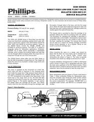
701S Valve with 101 Valve and Chamber<br />
Pilot Operated Level <strong>Co</strong>ntrol (Adjustable Level)<br />
701S Valve with 301E Valve and Chamber<br />
Pilot Operated Level <strong>Co</strong>ntrol (Fixed Level)<br />
8 Visit us at: www.haphillips.com or e-mail us at: info@haphillips.com 8<br />
A<br />
B<br />
A<br />
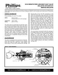
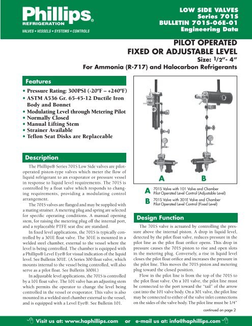
Design Function<br />
The 701S valve is actuated by controlling the pressure<br />
above the internal piston. A drop in liquid level,<br />
detected by the pilot float valve, reduces pressure in the<br />
pilot line as the pilot float orifice opens. This drop in<br />
pressure causes the 701S piston to rise and open slots<br />
in the metering plug. <strong>Co</strong>nversely, a rise in liquid level<br />
closes the pilot float orifice and increases the pressure in<br />
the pilot line. This moves the 701S piston and metering<br />
plug toward the closed position.<br />
Flow in the pilot line is from the top of the 701S to<br />
the pilot float valve. On a 101 valve, the pilot line must<br />
be connected to the port toward the “tail” of the arrow<br />
cast into the 101 valve body. On a 301 valve, the pilot line<br />
may be connected to either of the valve inlet connections<br />
on the sides of the valve body. The pilot line must be 1/4”<br />
B<br />
continued on page 2
Design Function- continued from page 1<br />
Nominal Pipe for proper operation of the 701S (3/8” OD<br />
copper tubing is also acceptable for halocarbon applications).<br />
A pressure gauge and shut-off valve in the pilot<br />
line are essential for indicating proper valve action. A<br />
solenoid valve in the pilot line will provide instantaneous<br />
shut-off of the 701S, and prevent liquid from flowing to<br />
the vessel or evaporator when the compressors are not<br />
operating.<br />
On ammonia applications, the float chamber’s lower<br />
“balance line” should not permit oil to collect and impair<br />
valve function. The “remote” pilot line, running from the<br />
outlet of the float valve to the downstream side of the<br />
701S or to the vessel, should be 1/2” Nominal Pipe.<br />
Isolation valves and a liquid bypass line with hand<br />
expansion valve will allow system operation during service<br />
or maintenance of the 701S valve.<br />
General Application for Series 701S Pilot Operated Valve<br />
with Series 101 Adjustable Level Pilot Float Valve<br />
PILOT<br />
OPERATED<br />
VALVE*<br />
701JRS<br />
701S<br />
701AS<br />
701BS<br />
SERIES 701 & SERIES 101 VALVE CORRELATION – SIZES & WEIGHTS<br />
STRAINER<br />
S701JR<br />
S701<br />
S701A<br />
S701B<br />
SERIES 701<br />
PORT<br />
3/8"<br />
9/16"<br />
9/16"<br />
23/32"<br />
23/32"<br />
7/8"<br />
1-1/4"<br />
PILOT FLOAT VALVE<br />
WITH CHAMBER<br />
NUMBER<br />
101VP18<br />
101VP18<br />
101VP26<br />
101VP26<br />
ORIFICE<br />
3/32"<br />
5/32"<br />
I.P.S.; THD.<br />
OR SOCKET<br />
I.P.S.; WELD<br />
NECK<br />
O.D. COPPER<br />
1/2", 3/4", 1" 1/2", 3/4", 1" 1-1/8", 1-3/8"<br />
3/32" 1", 1-1/4" 1", 1-1/4"<br />
1/8"<br />
1-1/2", 2"<br />
3"**<br />
AVAILABLE CONNECTIONS<br />
1-1/2", 2"<br />
1-5/8"<br />
2-1/8"<br />
PILOT<br />
OPERATED<br />
VALVE<br />
16<br />
20<br />
40<br />
SHIPPING WEIGHT (LBS.)<br />
P.O. VALVE<br />
WITH<br />
STRAINER<br />
25<br />
30<br />
70<br />
3" 3-1/8" 78 154<br />
P.O. VALVE<br />
STR. &<br />
FLOAT<br />
85<br />
90<br />
150<br />
234<br />
701BXS<br />
S701B<br />
1-9/16"<br />
101VP26<br />
3/16"<br />
--<br />
4"<br />
--<br />
86<br />
162<br />
242<br />
* ‘F’ suffix on a valve number indicates use with halocarbon refrigerant.<br />
**Socket only<br />
Page 2
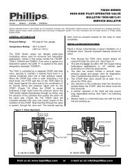
General Application for Series 701S Pilot Operated Valve<br />
with Series 301 Fixed Level Pilot Float Valve<br />
PILOT<br />
OPERATED<br />
VALVE*<br />
SERIES 701 & SERIES 301 VALVE CORRELATION – SIZES & WEIGHTS<br />
SERIES<br />
701 PORT<br />
STRAINER<br />
PILOT FLOAT VALVE<br />
WITH CHAMBER<br />
NUMBER<br />
ORIFICE<br />
I.P.S.; THD.<br />
OR SOCKET<br />
AVAILABLE CONNECTIONS<br />
I.P.S.; WELD<br />
NECK<br />
VALVE CAPACITIES – TONS<br />
O.D. COPPER<br />
PILOT<br />
OPERATED<br />
VALVE<br />
3/8" 3/32"<br />
701JRS S701JR 301E 1/2", 3/4", 1" 1/2", 3/4", 1" 1-1/8", 1-3/8" 16<br />
9/16" 1/8"<br />
9/16" 3/32"<br />
701S S701 301E 1", 1-1/4" 1", 1-1/4" 1-5/8" 20<br />
23/32" 1/8"<br />
23/32"<br />
701AS S701A 301E 9/64" 1-1/2", 2" 1-1/2", 2" 2-1/8" 40<br />
7/8"<br />
701BS 1-1/4" S701B 301G 5/32" 3"** 3" 3-1/8"<br />
701BXS 1-9/16" S701B 301J 3/16"<br />
78<br />
-- 4" -- 86<br />
* ‘F’ suffix on a valve number indicates use with halocarbon refrigerant. **Socket only.<br />
PILOT<br />
OPERATED<br />
VALVE**<br />
701JRS 3/8<br />
701S<br />
701AS<br />
701BS 1-1/4<br />
**Add suffix ‘F’ when ordering a valve for use with a halocarbon refrigerant.<br />
Calculated for operation with saturated liquid at the valve inlet. To<br />
develope these capacities, the pressure drop across the valve must<br />
be greater than one-half the inlet Absolute pressure. When liquid is<br />
subcooled, valve capacity will increase.<br />
‡ Valve capacities at 20 to 25 PSIG are 50% of these ratings.<br />
Outlet pressure must be 0 PSIG or less.<br />
Page 3<br />
SHIPPING WEIGHT (LBS.)<br />
P.O. VALVE<br />
WITH<br />
STRAINER<br />
30<br />
70<br />
P.O.<br />
VALVE<br />
STR. &<br />
FLOAT<br />
25 65<br />
AMMONIA (R-717)<br />
R22<br />
ORIFICE IN<br />
METERING<br />
CV<br />
INLET PRESSURE--PSIG<br />
INLET PRESSURE--PSIG<br />
INCHES<br />
PLUG<br />
80‡ 100 125 160 200 80‡ 100 125 160 200<br />
1.33 230.25 74 80 90 99 110 18 19 21 23 24<br />
2.37 430.25 -- -- -- -- -- 32 34 37 41 43<br />
2.98 445.25 -- -- -- -- -- 41 43 47 51 54<br />
1.7 245.25 95 100 115 125 140 23 24 26 28 31<br />
9/16 3.1 445.25 175 185 210 230 260 42 45 49 53 57<br />
5.2 445.38 -- -- -- -- -- 71 75 82 89 95<br />
23/32 6.7 445.43 -- -- -- -- -- 92 97 105 115 120<br />
5.8 245.32 320 350 395 430 485 79 84 91 99 105<br />
23/32 8.4 445.32 470 505 570 625 700 115 120 130 145 155<br />
11.1 845.32 620 670 755 825 925 150 160 175 190 200<br />
7/8 16.5 845.40 -- -- -- -- -- 225 240 260 280 300<br />
6.5 245.50 360 390 440 480 540 89 94 100 110 120<br />
11.0 445.50 610 660 750 815 915 150 160 175 190 200<br />
14.1 645.50 782 846 962 1050 1173 192 205 224 244 256<br />
22.5 845.50 1260 1350 1530 1670 1870 310 325 355 385 410<br />
23.9 1045.50 1330 1440 1630 1770 1990 325 345 375 410 440<br />
701BXS 1-9/16 35 60º 1950 2100 2370 2590 2900 475 500 550 590 645<br />
154<br />
162<br />
70<br />
110<br />
195<br />
203<br />
<strong>Co</strong>nsult H. A. <strong>Phillips</strong> & <strong>Co</strong>. if special applications,<br />
other refrigerants, or unusual liquid conditions prevail.
SPRING SELECTION TABLE<br />
VALVE TYPE<br />
PRESSURE DROP AVAILABLE ACROSS VALVE, PSI<br />
10-20* 20-40 40-60 60-100 100-160<br />
701JRS & 701 S 705-5L 705-10L 705-20L 705-35R 705-60R<br />
701AS 705A-10L 705A-20L 705A-30L 705A-60L 705A-110L<br />
701BS & 701BXS 705B-10L 705B-30L 705B-60L 705B-100L 705B-160L<br />
Pilot Pressure Drop to Open (PSIG) 5-6 10-12 16-20 30-40 50-70<br />
* Buna-N rubber seat discs available for tighter shut-off at low pressure drop.<br />
o<br />
F of Sub-<strong>Co</strong>oling<br />
Factor<br />
LIQUID SUB-COOLING FACTORS<br />
5 10 20 30 50<br />
1.25 1.47 1.75 1.9 2.2<br />
SERIES 701S PILOT OPERATED VALVES PARTS<br />
ITEM<br />
PART NUMBER<br />
PART<br />
NO.<br />
701JRS 701S 701AS 701BS 701BXS<br />
1 Cap Screw (4) 325 325 718 1459 1459<br />
2 Bonnet 702JRS 702S 702AS 702BS 702BXS<br />
3* Gasket, Bonnet 710JR 710 710A 710B 710B<br />
4* Spring 705-** 705-** 705A-** 705B-** 705B-**<br />
5 Piston 704JR 704 704A 704B 704BXS<br />
6 Valve Body 701JRS 701 701AS 701BS 701BXS<br />
7* Gasket, Flange (2) 506 725N 73 326Y 326Y<br />
8* Seat Disc 703JR 703 703A 703B 703BXS<br />
9 Seat 706JR 706 706A 706B --<br />
10 Metering Plug 707JR 707 707A 707B 707BXS<br />
11 Lifting Stem 711 711 711A 711B 711B<br />
12 Gasket, Seal Cap 720 720 720 720B 720B<br />
13 Packing Ring 775 775 775 777BN 777BN<br />
14 Gland 8 8 8 8B 8B<br />
15 Seal Cap 714 714 714 714B 714B<br />
*Recommended spare parts<br />
**See Spring Table above<br />
SERIES 701S VALVE DIMENSIONS (INCHES)<br />
Series 701S Flange<br />
Valve Type<br />
A B C D E F<br />
701JRS Oval 4.19 4.50 4.13 3.50 5.88 4.50<br />
701S Oval 4.19 4.50 5.00 4.00 6.13 4.50<br />
701AS Square 5.38 5.25 4.75 8.75 8.50 7.75<br />
701BS/BXS Square 6.88 6.88 6.00 10.00 12.00 10.00<br />
ORDERING INSTRUCTIONS<br />
Specify:<br />
1) Pilot Operated Valve<br />
2) With/Without Strainer<br />
3) Size & Type of Flanges<br />
4) Refrigerant, Capacity, & Pressures<br />
5) Sub-cooling (if any)<br />
6) Pilot Float Valve<br />
7) With/Without Chamber<br />
H. A. <strong>Phillips</strong> & <strong>Co</strong>.<br />
1612 Louise Drive<br />
South Elgin, IL 60177-2242 U.S.A.<br />
Phone: (630) 377-0050 • Fax: (630) 377-2706<br />
E-mail: info@haphillips.com<br />
or visit us @ www.haphillips.com