to download article supplement. - H. A. Phillips & Co.
to download article supplement. - H. A. Phillips & Co.
to download article supplement. - H. A. Phillips & Co.

Create successful ePaper yourself
Turn your PDF publications into a flip-book with our unique Google optimized e-Paper software.
VALVES | VESSELS | SYSTEMS | CONTROLS<br />
VALVES & ACCESSORIES
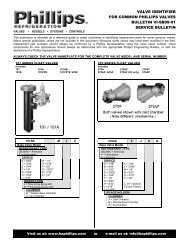
High Side <strong>Co</strong>ntrols<br />
270A Float <strong>Co</strong>ntrol<br />
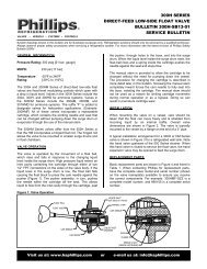
The 270A Series valves are direct feed High Side level controls. Mounted in a<br />
chamber balanced <strong>to</strong> a vessel, or directly in a sump, a rise in liquid level will open<br />
the orifice and allow the liquid <strong>to</strong> flow downstream.<br />
These valves have a simple needle and seat construction. The 270A valve has a<br />
single port, but the 270AX and 270AY valves are balanced port valves, allowing<br />
their use with larger orifices and at greater pressure drops across the valve.<br />
These valves are generally applied <strong>to</strong> refrigeration systems with a fixed charge.<br />
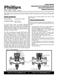
700H Series Pilot Operated <strong>Co</strong>ntrol<br />
270A Application Example<br />
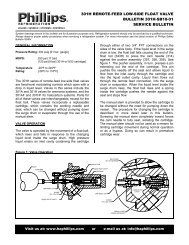
The 700H Series valves are pilot operated by a 275AP pilot float valve that modulates the flow of liquid refrigerant. These valves may<br />
also be applied <strong>to</strong> controlled pressure receivers, thermosyphon vessels, economizers, and for drainage of condensed vapor in heat<br />
reclaim vessels. These flanged pis<strong>to</strong>n-type valves have a manual lifting stem and replaceable PTFE seat disc.<br />
It is necessary <strong>to</strong> size the internal metering plug and spring for the design criteria <strong>to</strong> which the 700H valve is <strong>to</strong> be applied, including<br />
mass flow or <strong>to</strong>nnage and the inlet and outlet pressures of the valve. The valve is pilot operated by a remote pilot float valve with an<br />
orifice suitably sized for each 700H body size.<br />
The typical application of the 700H Series Pilot Operated Valve<br />
is <strong>to</strong> maintain a liquid seal in the condenser drain line, or in<br />
a thermosyphon vessel, utilizing a 275AP Pilot Float Valve in<br />
a chamber. The pilot float valve follows the upstream liquid<br />
level.<br />
As the condensing load increases, the 275AP float ball rises,<br />
slowly closing the pilot orifice. This reduces the pressure in<br />
the pilot line <strong>to</strong> the 700H valve, and pressure on <strong>to</strong>p of the<br />
pis<strong>to</strong>n bleeds <strong>to</strong> the downstream side of the 700H valve. The<br />
balance of forces causes the pis<strong>to</strong>n with metering plug <strong>to</strong><br />
rise, allowing more liquid <strong>to</strong> move downstream. Alternately,<br />
as the condensing load decreases, the float ball drops and<br />
opens the pilot orifice, thereby putting higher pressure on<br />
the 700H pis<strong>to</strong>n. The 700H valve then modulates <strong>to</strong>ward<br />
reducing the flow.<br />
The pilot line must be ¼” nominal pipe for proper operation<br />
(3/8” OD copper tubing is acceptable for halocarbon<br />
applications). It is imperative <strong>to</strong> install a pressure gauge in<br />
the pilot line between the bonnet of the 700H valve and the<br />
¼” nominal pipe size hand valve.<br />
Typical Pilot Operated<br />
High Side <strong>Co</strong>ntrol Arrangement<br />
1<br />
CRN: 0C10576.5C
Direct<br />
Acting<br />
Pilot<br />
Operated<br />
Valve<br />
Number***<br />
270A<br />
HIGH SIDE VALVE CAPACITIES (Tons*)<br />
Metering<br />
Ammonia (R-717)<br />
R-22<br />
Cv Plug or<br />
Inlet Pressure (PSIG)<br />
Inlet Pressure (PSIG)<br />
Orifice Size 60 80** 100 135 160 200 80** 100 125 160 200<br />
0.10 1/16 4.2 5.0 5.4 6.3 6.7 7.5 1.2 1.3 1.4 1.5 1.6<br />
0.14 5/64 6.2 7.4 8 9.4 10 11 1.8 1.9 2.1 2.2 2.4<br />
0.17 3/32 7.5 9.0 9.7 11 12 13 2.2 2.3 2.6 2.7 3.0<br />
0.38 1/8 17 20 22 26 27 30 4.9 5.2 5.8 6.1 6.6<br />
0.70 3/16 - - - - - - 9.1 9.5 10 11 12<br />
270AX 0.80 13/64 35 42 46 54 56 63 10 11 12 13 14<br />
270AY 1.20 3/8 54 63 70 82 84 94 15 16 18 20 21<br />
0.71 0 32 39 40 48 50 55 10 10 10 11 12<br />
1.04 1 47 57 60 70 75 82 14 15 15 16 18<br />
700JRH<br />
1.57 3 70 86 90 105 115 - 21 22 23 24 27<br />
2.18 5 98 119 125 150 164 - 29 30 31 33 38<br />
2.85 8 128 156 165 - - - 39 40 41 44 50<br />
3.34 10 - - - - - - 46 47 48 51 58<br />
0.78 0 35 42 45 53 55 60 - - - - -<br />
1.68 2 75 90 97 114 118 129 23 24 24 26 29<br />
2.8 5 125 150 163 190 204 220 38 39 40 43 49<br />
700XH 4.0 8 180 205 235 270 290 315 55 56 58 61 70<br />
4.7 10 210 255 274 320 340 370 65 66 68 72 82<br />
6.4 15 285 350 370 435 465 500 88 90 92 98 110<br />
8.0 20 360 440 465 545 580 630 110 112 115 120 135<br />
2.87 0 129 158 168 197 210 230 39 40 41 44 49<br />
5.91 5 265 325 345 405 430 465 81 83 85 90 100<br />
700AXH<br />
11.2 10 500 615 655 765 815 880 155 157 160 170 195<br />
14.5 15 650 795 845 990 1050 1140 200 205 210 220 250<br />
18.9 20 850 1030 1100 1290 1380 1490 260 265 270 290 330<br />
21.9 25 985 - - - - - 300 305 315 335 380<br />
4.04 0 180 220 235 275 295 320 55 56 58 62 70<br />
15.1 5 680 825 880 1030 1100 1190 205 210 215 230 260<br />
21.9 10 985 1200 1280 1500 1600 1730 300 305 315 335 380<br />
28.2 15 1250 1550 1650 1930 2050 2220 390 395 405 430 490<br />
700BXH 35.0 20 1575 1920 2050 2390 2550 - 480 490 505 535 610<br />
39.6 25 1780 2170 2310 2700 2890 - 545 555 570 605 680<br />
44.0 30 1980 2400 2570 3000 3200 - 605 615 630 675 765<br />
51.0 45 2200 2800 2980 3480 3720 - 700 715 730 780 885<br />
54.0 60 - - - - - - 760 770 790 840 950<br />
*Calculated for operation with saturated liquid at the valve inlet. To develop these capacities, the pressure drop across the valve must be greater than one-half the absolute<br />
inlet pressure. When the liquid is subcooled, the valve capacity will increase.<br />
** Valve capacities at 20 <strong>to</strong> 25 PSIG inlet pressure are approximately 50% of these ratings.<br />
*** 'F' suffix on valve number indicates use with halocarbon refrigerants.<br />
Pilot<br />
Operated<br />
Valve*<br />
700H SERIES VALVES DATA & 275AP VALVE CORRELATION<br />
Strainer<br />
275AP Pilot<br />
Float Valve*<br />
Orifice<br />
(in.)<br />
Available <strong>Co</strong>nnections (in.)<br />
I.P.S.,<br />
Thd. or<br />
Socket<br />
Weld<br />
Weld<br />
Neck<br />
O.D. <strong>Co</strong>pper<br />
Pilot<br />
Operated<br />
Valve<br />
P.O. Valve<br />
w/<br />
Strainer<br />
P.O. Valve,<br />
Str., Float w/<br />
Cast Iron<br />
Chamber<br />
High Side <strong>Co</strong>ntrols<br />
P.O. Valve,<br />
Str., Float w/<br />
Steel<br />
Chamber<br />
700JRH S701JR 1/16 1/2, 3/4 1/2, 3/4 1-1/8, 1-3/8 16 25 47 75<br />
700XH S701 1/16 1, 1-1/4 1, 1-1/4 1-5/8 20 30 52 80<br />
700AXH S701A 5/64 1-1/2, 2 1-1/2, 2 2-1/8 40 70 92 120<br />
700BXH S701B 3/32 3 3 3-1/8 78 154 172 200<br />
* 'F' suffix on valve number indicates use with halocarbon refrigerants.<br />
Weight (lbs.)<br />
ALTERNATE<br />
REFRIGERANT<br />
RATINGS<br />
R-22 Nominal<br />
Capacity Multipliers<br />
R-134a 0.82<br />
R-404a 0.74<br />
R-410a 1.10<br />
R-507a 0.82<br />
Valve<br />
Number<br />
700H SERIES VALVE SPRING SELECTION<br />
Spring Number<br />
(Number in brackets is the minimum required pressure drop across the pilot operated valve.*)<br />
700JRH 705-1L (5) 705-5L (20) 705-10L (44) 705-20L (70) -<br />
700XH 705-1L (5) 705-5L (16) 705-10L (30) 705-20L (60) -<br />
700AXH 705A-2L (5) 705A-10L (30) 705A-30L (40) 705A-60L (80) -<br />
700BXH 705B-3L (5) 705B-10L (16) 705B-30L (30) 705B-60L (44) 705B-100L (80)<br />
*When the MINIMUM pressure drop available across the 700H series valve falls between two successive numbers shown<br />
in brackets, choose the spring for the lower pressure drop.<br />
When the 700H Series valves are used in applications where a flash tank or controlled pressure<br />
receiver is involved, a correction fac<strong>to</strong>r must be made <strong>to</strong> the valve capacities shown in the table.<br />
This accounts for the typically lower pressure drop available across the pilot valve.<br />
The table <strong>to</strong> the right indicates the multipliers <strong>to</strong> be used at various upstream pressures.<br />
Flash Tank<br />
Pressure<br />
Multipliers for 700H Capacities<br />
Upstream Pressure (PSIG)<br />
(PSIG) 80 100 135 160 200<br />
45 0.83 0.95 1.0 - -<br />
60 0.80 0.85 0.90 0.96 1.0<br />
70 - 0.82 0.88 0.92 1.0<br />
85 - - 0.85 0.86 0.94<br />
110 - - 0.70 0.80 0.85<br />
2
Low Side <strong>Co</strong>ntrols - Direct Acting<br />
101 Series Float <strong>Co</strong>ntrol<br />
The 101 Series valve float ball is linked through a forked lever <strong>to</strong> act<br />
upon a needle or plunger directly over the orifice controlling the<br />
refrigerant flow. A spring is installed over the needle, working in<br />
opposition <strong>to</strong> the lever, which supports the weight of the float ball.<br />
The spring pressure can be regulated by an external adjusting stem<br />
<strong>to</strong> make the float lighter or heavier, causing the liquid level <strong>to</strong> be<br />
lower or higher <strong>to</strong> any desired point within the range of the spring.<br />
Turning the adjusting stem counter-clockwise will raise the liquid<br />
level. Total level change, at a particular setting, from a fully closed <strong>to</strong><br />
a fully open valve is about 2”.<br />
Unless otherwise stated by the vessel manufacturer, liquid level<br />
set point should typically be 2/3 <strong>to</strong> 3/4 of vessel diameter for<br />
flooded ammonia chillers and 40% of vessel diameter for flooded<br />
halocarbon chillers. A separating vessel above the chiller is<br />
recommended.<br />
300H Series Float <strong>Co</strong>ntrol<br />
The 300H Series internal mounting fixed level low side float valves<br />
are modulation type liquid level controls, designed primarily for<br />
use with ammonia. The valves incorporate a replaceable cartridge<br />
that contains the working needle and seat. The cartridge can be<br />
removed without pump down of the surge drum or evapora<strong>to</strong>r due<br />
<strong>to</strong> a secondary shut-off arrangement built in<strong>to</strong> the valve. When used<br />
in halocarbon systems, these valves can be supplied with heavier<br />
float balls.<br />
301E Series Float <strong>Co</strong>ntrol<br />
The 301E Series external mounting fixed level float valves are<br />
modulating liquid level controls. The welded steel chamber has a<br />
<strong>Phillips</strong> Level Eye for a visual check of the liquid level. The valves<br />
incorporate a replaceable cartridge that contains the working<br />
needle and seat. Pump down of the chamber is required <strong>to</strong> service<br />
the valve. These valves are for use with unitary surge drums and<br />
evapora<strong>to</strong>rs, for intercooler or desuperheater level control, small<br />
ammonia or halocarbon chillers, or other applications requiring<br />
external level control. A remote feed line is required from the<br />
valve outlet <strong>to</strong> the vessel or evapora<strong>to</strong>r. When used in halocarbon<br />
systems, these valves are equipped with heavier float balls.<br />
3
Low Side <strong>Co</strong>ntrols - Direct Acting<br />
301H Series Float <strong>Co</strong>ntrol<br />
The 301H Series internal mounting fixed level low side float valves<br />
are modulating liquid level controls. They are fixed level controls<br />
with a remote feed line required from the valve outlet <strong>to</strong> the<br />
evapora<strong>to</strong>r or surge drum. The valves incorporate a replaceable<br />
cartridge that contains the working needle and seat. The cartridge<br />
can be removed without pump down of the surge drum or<br />
evapora<strong>to</strong>r due <strong>to</strong> a secondary shut-off arrangement built in<strong>to</strong> the<br />
valve. The stem on the front of the valve is for operating the backseating<br />
arrangement and is not <strong>to</strong> be used ad a hand expansion<br />
bypass. When used in halocarbon systems, these valves can be<br />
supplied with heavier float balls.<br />
Valve<br />
Number***<br />
101<br />
101A<br />
300H<br />
300HM<br />
300A<br />
300AM<br />
LOW SIDE VALVE CAPACITIES (Tons)*<br />
Ammonia (R-717) R-22<br />
Orifice<br />
Cv<br />
Inlet Pressure (PSIG)<br />
Inlet Pressure (PSIG)<br />
[in.]<br />
80** 100 125 160 200 80** 100 125 160 200<br />
5/64 0.14 7.4 7.8 9.1 9.9 11 1.8 1.9 2.1 2.3 2.4<br />
3/32 0.18 9.3 11 11 12 14 2.4 2.5 2.7 2.9 3.2<br />
1/8 0.29 15 17 18 20 23 3.8 4.1 4.3 4.7 5.1<br />
5/32 0.34 18 19 22 24 27 4.4 4.7 5.0 5.5 5.9<br />
3/16 0.47 25 27 30 33 37 6.1 6.4 7.0 7.7 8.2<br />
3/16 0.55 29 32 36 39 44 6.9 7.4 8.0 9.2 9.7<br />
1/4 0.96 51 55 62 68 76 12 13 14 16 17<br />
5/16 1.1 58 63 71 77 87 14 15 16 18 19<br />
3/8 1.4 73 79 89 97 109 18 19 21 22 24<br />
3/32D 0.076 3.7 4.0 4.6 4.9 5.5 0.94 0.94 1.1 1.2 1.3<br />
3/32 0.098 4.8 5.1 5.9 6.3 7.1 1.2 1.2 1.4 1.5 1.6<br />
7/64 0.16 7.8 8.4 9.5 10 12 1.9 2.0 2.2 2.4 2.5<br />
1/8 0.22 11 12 13 14 16 2.6 2.8 3.0 3.3 3.5<br />
9/64 0.26 13 14 15 17 19 3.1 3.3 3.6 3.9 4.0<br />
5/32 0.35 16 18 21 23 25 4.2 4.4 4.8 5.2 5.6<br />
3/16 0.40 20 22 24 27 29 4.8 5.0 5.5 6.0 6.4<br />
5/64 0.056 2.8 3.0 3.3 3.6 4.1 0.65 0.70 0.80 0.85 0.90<br />
3/32 0.11 5.5 6.0 6.6 7.3 8.2 1.3 1.4 1.6 1.7 1.8<br />
301E 7/64 0.18 9.0 9.7 11 12 13 2.2 2.3 2.5 2.8 3.0<br />
1/8 0.26 13 14 16 17 19 3.2 3.4 3.7 4.0 4.3<br />
9/64 0.31 15 17 19 21 23 3.8 4.0 4.4 4.7 5.1<br />
301G<br />
5/32 0.40 18 20 22 25 28 4.0 4.2 5.0 5.5 5.9<br />
3/16 0.43 22 23 26 29 32 5.3 5.5 6.0 6.5 7.1<br />
3/16 0.56 28 30 34 37 42 6.9 7.2 7.9 8.6 9.1<br />
301J## 7/32 0.80 40 43 49 53 60 9.8 10 11 12 13<br />
9/32† 0.97 48 52 - - - 12 12 14 15 16<br />
301K 9/32 0.97 48 52 59 66 74 12 12 14 15 16<br />
3/16 0.55 28 30 34 37 42 6.8 7.1 7.7 8.4 8.9<br />
301H 7/32 0.78 40 43 49 53 60 9.5 9.8 11 12 13<br />
9/32 1.0 48 52 - - - 12 12 14 15 16<br />
301A 9/32 1.0 48 52 59 66 74 12 12 14 15 16<br />
*Calculated for operation with saturated liquid at the valve inlet. To develop these capacities, the pressure drop across the valve must be greater<br />
than one-half the absolute inlet pressure. When the liquid is subcooled, the valve capacity will increase. See page 6 for Liquid Subcooling Fac<strong>to</strong>rs<br />
and Alternate Refrigerant Ratings.<br />
** Valve capacities at 20 <strong>to</strong> 25 PSIG inlet pressure are approximately 50% of these ratings. Outlet pressure must be 0 PSIG or less.<br />
*** 'F' suffix on valve number indicates use with halocarbon refrigerants.<br />
## The 3/16" and 7/32" orifices shown for the 301J valve can be used in the 301K valve at the indicated ratings.<br />
† Limited <strong>to</strong> a maximum pressure drop of 120 PSI with R-717<br />
CRN: 0C10576.5C<br />
4
Low Side <strong>Co</strong>ntrols - Pilot Operated<br />
701S Series Low Side Valve<br />
The 701S Series Low side valves are pilot operated valves<br />
which meter the flow of liquid refrigerant <strong>to</strong> an evapora<strong>to</strong>r or<br />
pressure vessel in response <strong>to</strong> liquid level requirements. The<br />
701S is controlled by a float valve which responds <strong>to</strong> changing<br />
requirements, providing a modulating control arrangement.<br />
The 701S valves are flanged and may be supplied with a mating<br />
strainer. A metering plug and spring are selected for specific<br />
operating conditions. A manual opening stem, for raising the<br />
metering plug off the internal port and a replaceable PTFE seat disc<br />
are standard.<br />
In fixed level applications, the 701S is typically controlled by a<br />
301E float valve. The 301E is mounted in a welded steel chamber,<br />
external <strong>to</strong> the vessel where the level is being controlled. The<br />
chamber is equipped with a <strong>Phillips</strong> Level Eye for visual indication<br />
of the liquid level. A 300H Series float valve, which mounts internal<br />
<strong>to</strong> the vessel being controlled, will also serve as a pilot float.<br />
General Application for 701S Series Pilot Operated<br />
Valve with 101 Series Adjustable Level Pilot Float Valve<br />
In adjustable level applications, the 701S is controlled by a 101<br />
float valve. The 101 valve has an adjusting stem which permits<br />
the opera<strong>to</strong>r <strong>to</strong> change the level being controlled in the vessel or<br />
evapora<strong>to</strong>r. This valve is also mounted in a welded steel chamber<br />
external <strong>to</strong> the vessel, and is equipped with a Level Eye.<br />
The 701S valve is actuated by controlling the pressure above the<br />
internal pis<strong>to</strong>n. A drop in liquid level, detected by the pilot valve,<br />
reduces pressure in the pilot line as the pilot orifice opens. This<br />
drop in pressure causes the 701S pis<strong>to</strong>n <strong>to</strong> rise and open slots in<br />
the metering plug. <strong>Co</strong>nversely, a rise in liquid level closes the pilot<br />
float orifice and increases the pressure in the pilot line, moving the<br />
pis<strong>to</strong>n and metering plug <strong>to</strong>ward the closed position.<br />
Flow in the pilot line is from the <strong>to</strong>p of the 701S <strong>to</strong> the pilot float<br />
valve. On a 101 valve, the pilot line must be connected <strong>to</strong> the port<br />
<strong>to</strong>ward the “tail” of the arrow cast in the 101 valve body. On a 301E<br />
valve, the pilot line may be connected <strong>to</strong> either of the valve inlet<br />
connections on the sides of the valve body. The pilot line must be<br />
¼” Nominal Pipe for proper operation (3/8” OD copper tubing is<br />
also acceptable for halocarbon applications). See the application<br />
diagrams for valve layouts.<br />
General Application for 701S Series Pilot Operated<br />
Valve with 301E Series Fixed Level Pilot Float Valve<br />
5
Low Side <strong>Co</strong>ntrols - Pilot Operated<br />
Valve<br />
Number***<br />
701JRS<br />
Port<br />
Diameter<br />
(in.)<br />
Metering<br />
Plug<br />
Cv<br />
Inlet Pressure (PSIG)<br />
Inlet Pressure (PSIG)<br />
80** 100 125 160 200 80** 100 125 160 200<br />
1.33 230.25 74 80 90 99 110 18 19 21 23 24<br />
3/8 2.37 430.25 130 140 160 175 195 32 34 37 41 43<br />
2.98 445.25 160 180 200 220 245 41 43 47 51 54<br />
9/16 5.33 845.25 - - - - - 52 55 58 59 73<br />
1.7 245.25 95 100 115 125 140 23 24 26 28 31<br />
701S<br />
9/16 3.1 445.25 175 185 210 230 260 42 45 49 53 57<br />
5.2 445.38 290 310 350 385 430 71 75 82 89 95<br />
23/32 6.7 445.43 - - - - - 92 97 105 115 120<br />
5.8 245.32 320 350 395 430 485 79 84 91 99 105<br />
701AS<br />
23/32 8.4 445.32 470 505 570 625 700 115 120 130 145 155<br />
11.1 845.32 620 670 755 825 925 150 160 175 190 200<br />
7/8 16.5 845.40 920 990 1120 1220 1370 225 240 260 280 300<br />
6.5 245.50 360 390 440 480 540 89 94 100 110 120<br />
11.0 445.50 610 660 750 815 915 150 160 175 190 200<br />
701BS 1-1/4 14.1 645.50 782 846 962 1050 1173 192 205 224 244 256<br />
22.5 845.50 1260 1350 1530 1670 1870 310 325 355 385 410<br />
23.9 1045.50 1330 1440 1630 1770 1990 325 345 375 410 440<br />
701BXS 1-9/16 35 60° 1950 2100 2370 2590 2900 475 500 550 590 645<br />
*Calculated for operation with saturated liquid at the valve inlet. To develop these capacities, the pressure drop across the valve must be greater than one-half the<br />
absolute inlet pressure. When the liquid is subcooled, the valve capacity will increase.<br />
** Valve capacities at 20 <strong>to</strong> 25 PSIG inlet pressure are approximately 50% of these ratings.<br />
*** 'F' suffix on valve number indicates use with halocarbon refrigerants.<br />
701S SERIES VALVE CAPACITIES (Tons*)<br />
Pilot Float Valve<br />
with Chamber<br />
Float Orifice<br />
Valve Size<br />
Number (in.)<br />
Ammonia (R-717)<br />
701S & 101/301E SERIES VALVE CORRELATION - SIZES & WEIGHTS<br />
Pilot<br />
Operated<br />
Valve<br />
Number*<br />
Port Size<br />
(in.)<br />
Strainer<br />
Number<br />
R-22<br />
I.P.S., Thd.<br />
Pilot P.O. Valve<br />
Weld O.D.<br />
or Socket<br />
Operated w/<br />
Neck <strong>Co</strong>pper<br />
Weld<br />
Valve Strainer<br />
101VP18 16 25 85<br />
P.O. Valve,<br />
Str., Float<br />
3/8<br />
3/32<br />
301E 1/2 1/2 1-1/8 16 25 65<br />
701JRS<br />
S701JR<br />
101VP18 3/32 3/4 3/4 1-3/8 16 25 85<br />
9/16<br />
301E 1/8 16 25 65<br />
101VP18 20 30 90<br />
9/16<br />
3/32<br />
301E 1 1<br />
20 30 70<br />
701S<br />
S701<br />
1-5/8<br />
101VP18 3/32 1-1/4 1-1/4<br />
20 30 90<br />
23/32<br />
301E 1/8 20 30 70<br />
101VP26 1/8 40 70 150<br />
23/32<br />
301E 9/64 1-1/2 1-1/2<br />
40 70 110<br />
701AS<br />
S701A<br />
2-1/8<br />
101VP26 1/8 2 2<br />
40 70 150<br />
7/8<br />
301E 9/64 40 70 110<br />
101VP26 78 154 234<br />
701BS 1-1/4<br />
5/32 3 3 3-1/8<br />
301G 78 154 195<br />
S701B<br />
101VP26 3/16 86 162 242<br />
701BXS 1-9/16 - 4 -<br />
301J 3/32 86 162 203<br />
* 'F' suffix on valve number indicates use with halocarbon refrigerants.<br />
Available <strong>Co</strong>nnections<br />
(in.)<br />
Weight<br />
(lbs.)<br />
701S SERIES VALVE SPRING SELECTION TABLE<br />
Valve Number<br />
Pressure Drop Available Across Valve (PSI)<br />
10-20* 20-40 40-60 60-100 100-160<br />
701JRS & 701S 705-5L 705-10L 705-20L 705-35R 705-60R<br />
701AS 705A-10L 705A-20L 705A-30L 705A-60L 705A-110L<br />
701BS & 701BXS 705B-10L 705B-30L 705B-60L 705B-100L 705B-160L<br />
Pilot Pressure Drop<br />
<strong>to</strong> Open (PSIG)<br />
5-6 10-12 16-20 30-40 50-70<br />
LIQUID SUBCOOLING FACTORS<br />
°F of Subcooling 5 10 20 30 50<br />
Fac<strong>to</strong>r 1.25 1.47 1.75 1.9 2.2<br />
ALTERNATE<br />
REFRIGERANT<br />
RATINGS<br />
R-22 Nominal<br />
Capacity Multipliers<br />
R-134a 0.82<br />
R-404a 0.74<br />
R-410a 1.10<br />
R-507a 0.82<br />
CRN: 0C10576.5C<br />
6
Check Valves<br />
600 Series Check Valve<br />
The 600 Series flanged, in-line disc-type check<br />
valves are spring closing with a light spring. They<br />
may be installed in vertical or horizontal runs.<br />
There is a removable back plate that allows the<br />
valve <strong>to</strong> be disassembled for maintenance.<br />
The 600D has a metal-<strong>to</strong>-metal seat. The 600D2<br />
and 600D3 check valves incorporate the Durabla<br />
check valve unit. The 600D Series and ‘S’ suffix<br />
valves require about 2 psi pressure drop <strong>to</strong> open.<br />
The 600J and 600K Series valves are Teflon seated<br />
valves. When ordered without the ‘S’ suffix,<br />
they are supplied with a light spring with a ¼<br />
psi cracking pressure, making them suitable for<br />
gravity drain lines.<br />
The 600 Series check valves prevent reverse flow<br />
of refrigerant in suction, hot gas and liquid lines.<br />
These valves are suitable for liquid refrigerant<br />
gravity drain applications, pump discharge and<br />
suction. When used for gravity drain, they should<br />
be mounted vertically. These valves are designed<br />
for a 300 psi maximum working pressure. When<br />
used in hot gas defrost applications, they are<br />
installed between the drain pan and the hot gas<br />
inlet <strong>to</strong> the evapora<strong>to</strong>r. In this manner, the valve<br />
prevents liquid from collecting in the drain pan<br />
coil during normal evapora<strong>to</strong>r operation.<br />
The 600 Series check valves are not particularly<br />
suitable for reciprocating compressor discharge<br />
applications and where flow pulsation sets up a<br />
harmonious frequency <strong>to</strong> that of the valve.<br />
The 600 Series check valve is normally closed, light<br />
spring actuated. When the refrigerant mass flow<br />
is sufficient <strong>to</strong> create a pressure drop across the<br />
valve <strong>to</strong> overcome the force of the closing spring,<br />
the disc is forced away from its seat, permitting<br />
flow. As the mass flow decreases, the pressure drop<br />
across the valve will decrease, and the disc will be<br />
forced back against its seat by the closing spring.<br />
Valve Number<br />
Orifice<br />
Flanges<br />
Weight<br />
Size Flange Flange Sizes<br />
Bolts<br />
(lbs.)<br />
(in.) Type<br />
(in.)<br />
No. Size (in.)<br />
600D2 5/8 Oval 1/2, 3/4 2 5/8 4<br />
600D3 7/8 Oval 1 2 5/8 5.5<br />
600JR 1 Oval 1/2, 3/4, 1 2 5/8 5<br />
600K* 1-5/16 Square 1, 1-1/4 4 1/2 7<br />
600J 1-1/2 Square 1-1/4, 1-1/2 4 1/2 10<br />
600AK* 1-9/16 Square 1-1/2, 2 4 5/8 10.5<br />
600AJ 2 Square 1-1/2, 2 4 5/8 12<br />
600BJ* 3 Square 3 4 3/4 30<br />
600DJ* 4 Square 4 4 7/8 45<br />
1/2, 3/4, 1 (FPT, SW)<br />
700JRX, 700JRS 3/4 Oval<br />
1-1/8, 1-3/8 (ODC)<br />
2 1/2 14<br />
1, 1-1/4 (FPT, SW, WN)<br />
700X, 700XS, 700XT 1 Oval<br />
1-5/8 (ODC)<br />
2 5/8 20<br />
700AX, 700AXS, 700AXT 1-1/2<br />
1-1/4, 1-1/2, 2 (FPT, SW, WN)<br />
Square<br />
2-1/8 (ODC)<br />
4 5/8 40<br />
700BX, 700BXS, 700BXT 2-1/4<br />
3 (SW, WN)<br />
Square<br />
3-1/8 (ODC)<br />
4 3/4 75<br />
*If ordered with suffix 'S', the valve will be supplied with a heavy spring (not suitable for gravity drain).<br />
*Only these valves have the 1/4" FPT purge connection.<br />
Valve<br />
Number<br />
600D2<br />
600 SERIES VALVE CONFIGURATIONS<br />
Approx.<br />
DP <strong>to</strong><br />
Open<br />
2 psid<br />
CHECK VALVES<br />
Flange<br />
Sizes<br />
Avail.<br />
1/2"<br />
3/4"<br />
Body<br />
Material<br />
Machined<br />
Steel<br />
(Fig. 1)<br />
Purge<br />
Line<br />
<strong>Co</strong>nn.<br />
Wolfe-<br />
Linde<br />
Ref.<br />
- -<br />
600D3 2 psid 1" - -<br />
1/2"<br />
5970<br />
600JR
Check Valves<br />
700X Series Check Valve<br />
The 700X Series flanged in-line pis<strong>to</strong>n type check valves are spring<br />
closing and can be supplied with a 2, 5, 10, 20, 35, 50, 60, 70 and<br />
90 pound differential spring <strong>to</strong> suit your application. They have a<br />
manual lifting stem and replaceable PTFE seat disc.<br />
The 700X Series check valves prevent reverse flow of refrigerant<br />
in suction, hot gas and liquid lines. These valves are applicable for<br />
reciprocating compressor discharge line service, refrigerant pump<br />
discharge and suction line service and can be applied as a hot<br />
defrost relief valve. These valves can also be applied as the outlet<br />
check valve for various liquid transfer systems.<br />
The 700X Series check valve is normally closed, spring actuated.<br />
When the refrigerant mass flow is sufficient <strong>to</strong> create a pressure<br />
drop across the valve <strong>to</strong> overcome the force of its closing spring, the<br />
disc is forced away from its seat, permitting flow. As the mass flow<br />
decreases, the pressure drop across the disc will decrease and the<br />
disc will be forced back against its seat by the closing spring.<br />
PSI<br />
Spring Part Numbers<br />
Differential 700JRX 700X 700A & AX 700B & BX<br />
2 705-1L 705-5L 705A-2L 705B-3L<br />
5 705-5L 705-10L 705A-10L 705B-10L<br />
10 705-10L 705-20L 705A-20L 705B-30L<br />
20 705-20L 705-35L 705A-30L 705B-60L<br />
35 705-35L 705-60L 705A-60L -<br />
50 705-50L 705-90L - -<br />
60 705-60L - - -<br />
70 705-70L 705-130L 705A-110L -<br />
90 705-90L - 705A-165L -<br />
700S<br />
Valve<br />
700X VALVE SPRING TABLE<br />
Hot Gas Defrost Arrangement<br />
700X<br />
Valve<br />
700S Series Check Valve<br />
The 700S Series flanged, pis<strong>to</strong>n type, gas pressure powered<br />
valves are normally open by a spring beneath the valve pis<strong>to</strong>n.<br />
All are equipped with a Manual Lift Stem with a Seal Cap closure.<br />
The pilot line connection in the bonnet is 1/4” FPT.<br />
The 700S Series valve is designed <strong>to</strong> be applied as a Suction S<strong>to</strong>p<br />
Valve in suction lines. It also may be applied <strong>to</strong> liquid legs and<br />
gas return legs on flooded evapora<strong>to</strong>rs and liquid drain lines in<br />
transfer systems. Since the valve is spring opening, no pressure<br />
is required <strong>to</strong> open the valve. On gravity drain application, flow is<br />
unrestricted.<br />
The 700S valve is a normally open valve. It is closed by gas<br />
pressure from a remote source by energizing a pilot solenoid<br />
valve. The gas enters the valve through the 1/4” FPT connection<br />
in the <strong>to</strong>p of the valve bonnet and acts upon the <strong>to</strong>p of the<br />
pis<strong>to</strong>n, forcing the seat disc down on the main valve seat bead,<br />
and s<strong>to</strong>pping the refrigerant flow through the main valve. In<br />
order for the valve <strong>to</strong> close, the inlet pilot pressure on <strong>to</strong>p of<br />
the pis<strong>to</strong>n must be a minimum of 7 psi higher than the inlet<br />
pressure <strong>to</strong> the valve. For the valve <strong>to</strong> open, the solenoid in the<br />
remote pilot line must be de-energized. The higher pressure<br />
above the pis<strong>to</strong>n vents around the pis<strong>to</strong>n and approaches the<br />
lower pressure at the outlet of the valve. The spring under the<br />
pis<strong>to</strong>n forces the pis<strong>to</strong>n up, opening the valve fully <strong>to</strong> allow<br />
refrigerant flow.<br />
700XT Series 3-Way Check Valve<br />
The 700XT Series 3-way check valves are flanged in-line pis<strong>to</strong>n type<br />
check valves with a replaceable seat disc made from PTFE. They have<br />
a spring beneath the pis<strong>to</strong>n that holds the valve in an open position<br />
during normal operation so that no bleed <strong>to</strong> the downstream side is<br />
necessary <strong>to</strong> maintain a fully open port.<br />
A line from a high pressure gas source enters the 3-way check valve<br />
through the <strong>to</strong>p bonnet, and is normally closed utilizing a solenoid<br />
valve. When the solenoid valve is opened high pressure gas enters<br />
above the pis<strong>to</strong>n and closes the main port. Gas then flows through<br />
the center of the pis<strong>to</strong>n <strong>to</strong> the upstream side of the valve in the<br />
direction opposite <strong>to</strong> the arrow on the valve body. This will raise the<br />
upstream pressure <strong>to</strong> the level determined by a regula<strong>to</strong>r installed<br />
in the system. While the main port is closed there is a small bleed<br />
<strong>to</strong> the downstream side. When the solenoid valve is closed, the<br />
3-way check valve immediately opens and res<strong>to</strong>res full flow in the<br />
direction of the arrow.<br />
CRN: 0C10576.5C<br />
8
3-Way Valves<br />
The 3000N and 3000AN Au<strong>to</strong>matic 3-Way valves are configured<br />
with three external ports. The high pressure port (marked “HP”) is<br />
the inlet for pressurized gas. The low pressure port (marked “LP”)<br />
is the vent port. The center “common” port is open <strong>to</strong> either the HP<br />
or LP port, depending on the position of the internal pis<strong>to</strong>ns, as<br />
described a little below.<br />
The 3-Way valves are typically used on gas-pumped liquid transfer<br />
or recirculating systems. The valve’s common port is connected <strong>to</strong><br />
the <strong>to</strong>p of the pumper drum (dump trap). The LP port is connected<br />
<strong>to</strong> the suction accumula<strong>to</strong>r, above the level of the liquid but below<br />
the suction connection on the accumula<strong>to</strong>r. High pressure gas is fed<br />
<strong>to</strong> the HP port.<br />
With the 3-Way valve connected as described above and the<br />
solenoid de-energized, the pathway between the common and LP<br />
(vent) ports is held open. This is accomplished by high pressure gas<br />
and an internal spring which hold the smaller (HP) pis<strong>to</strong>n closed<br />
against the HP seat. The LP port is open. This “vent” position allows<br />
the pumper drum <strong>to</strong> vent <strong>to</strong> the suction accumula<strong>to</strong>r while it fills<br />
with liquid.<br />
When the solenoid is energized, high pressure gas is directed<br />
internally <strong>to</strong> the space above the larger (LP) pis<strong>to</strong>n. This causes the<br />
pis<strong>to</strong>ns <strong>to</strong> move in unison, closing the LP seat and the path between<br />
the LP and common ports while simultaneously opening the HP<br />
seat and the path between the HP and common ports. This is the<br />
“high pressure” position. The high pressure gas now flowing in<strong>to</strong><br />
the pumper drum through the common port can push the liquid<br />
<strong>to</strong> another location in the system. Typically, the high pressure gas<br />
should be regulated <strong>to</strong> 10 <strong>to</strong> 20 psi above the liquid destination<br />
pressure. This may need <strong>to</strong> be increased for long pipe distances.<br />
However, unnecessarily high pressure can lead <strong>to</strong> premature valve<br />
wear.<br />
The 3000N Series valves incorporate a manual opening stem below<br />
the solenoid. When this stem is screwed in completely, the valve<br />
will au<strong>to</strong>matically switch from the vent <strong>to</strong> the high pressure position<br />
when the solenoid coil is energized. Opening the stem ½-turn will<br />
manually cause the valve <strong>to</strong> switch from vent <strong>to</strong> high pressure.<br />
9<br />
CRN: 0C1057.5CADD1
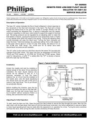
Oil Level Valves<br />
270A<br />
The 270A High Side Float Valve, opening on a rise in level, will<br />
transfer oil from a discharge line oil separa<strong>to</strong>r <strong>to</strong> the crankcase of<br />
the compressor or <strong>to</strong> an oil reservoir. This valve is used for oil in<br />
ammonia and halocarbon systems. The standard orifice supplied<br />
in the valve is 3/32” and will operate <strong>to</strong> a pressure drop of 250<br />
psi maximum. The capacity of the valve with oil, when fitted with<br />
the standard 3/32” orifice, is approximately 1-1/2 GPM at 100 psi<br />
pressure drop.<br />
OIL DRAIN VALVE<br />
Orifice Weight (lbs.)<br />
Valve<br />
Size Valve Valve with Cast<br />
Number<br />
(in.) Only Iron Chamber<br />
270A 3/32 8 22<br />
275AF<br />
The 275AF Low Side Float valve can be used <strong>to</strong> maintain the oil<br />
level in the crankcase of a compressor. For multiple compressor<br />
applications, a 275AF valve should be installed on each compressor.<br />
In this case, feed would be from an oil reservoir at an equal or<br />
greater pressure than the compressor crankcase. If the oil reservoir<br />
is at a pressure equal <strong>to</strong> the compressor crankcase, it must be<br />
elevated at least two feet above the desired compressor crankcase<br />
oil level so that gravity feed can take place. When the oil reservoir<br />
is at a greater pressure than the crankcase, it may be mounted low.<br />
<strong>Co</strong>nsult the table below for the maximum orifice size that can be<br />
used with various reservoir pressures.<br />
275AF OIL VALVE CAPACITIES<br />
GPM Oil<br />
Orifice<br />
Size<br />
(in.)<br />
Cv<br />
1 Ft.<br />
Head<br />
10 PSI<br />
Drop<br />
20 PSI<br />
Drop*<br />
Weight (lbs.)<br />
Valve<br />
Only<br />
Valve<br />
with Cast<br />
Iron<br />
Chamber<br />
1/16 0.095 0.06 0.3 0.42<br />
5/64 0.140 0.08 0.4 -<br />
3/32 0.170 0.10 - - 8 22<br />
1/8 0.380 0.22 - -<br />
3/16 0.700 0.40 - -<br />
*Do not use the 275AF valve for pressure drops greater than 20 PSI. When higher<br />
pressure drops are required, consult <strong>Phillips</strong> regarding the use of other low side valves.<br />
270A High Side Oil Drain Valve Application<br />
275AF Low Side Float Valve application <strong>to</strong> maintain oil level<br />
in compressor crank case, feeding from an oil reservoir.<br />
MOUNTING FLANGES<br />
FOR DIRECT MOUNTING ON TANK OR RESERVOIR<br />
Part<br />
Thickness Weld To<br />
Weight<br />
Type<br />
Number<br />
(in.) Pipe Length (in.) (lbs.)<br />
298A Socket Weld 0.50 2-1/2" S/40 2-1/2 2<br />
250WF4 Weld Neck 1.13 4" S/40 2-1/2 4<br />
CRN:0C10576.5C<br />
10
Accessories<br />
Level Eye Sight Glass<br />
Description and Function<br />
The <strong>Phillips</strong> Level Eye is a reliable, industrial-type sight glass.<br />
The Reflex lens indicates the true level of liquid present without<br />
requiring a second lens. The lens appears dark in the presence<br />
of liquid and clear when liquid is not present. Both Reflex and<br />
clear lenses are suitable for refrigerant vessels such as receivers,<br />
intercoolers, suction accumula<strong>to</strong>rs, oil separa<strong>to</strong>rs, surge drums, oil<br />
pots, columns, and liquid line indica<strong>to</strong>rs.<br />
The standard length frost shield allows clear vision with refrigerant<br />
temperatures down <strong>to</strong> -20°F/-29°C, and a 1” longer frost shield is<br />
available for refrigerant temperatures below -20°F/-29°C. The lowest<br />
temperature the Level Eye is suited for is -60°F/-51°C.<br />
The 1100 Series Level Eye is machined from SA36 material, as<br />
specified in Section VIII, Division I of the ASME Boiler & Pressure<br />
Vessel <strong>Co</strong>de. The housing may be welded directly in<strong>to</strong> ASME <strong>Co</strong>de<br />
vessels. The welding end is dimensioned <strong>to</strong> a nominal 1-1/2”<br />
IPS schedule 80 pipe. The weld neck or threaded neck is also<br />
dimensioned <strong>to</strong> a nominal 1-1/2” schedule 80 pipe. All retainers<br />
are annealed 416 stainless steel forgings. Type 304 stainless steel<br />
housings are also available.<br />
The 1101 clear lens and 1101R Reflex lens and are both made<br />
of borosilicate glass. Both are used with a Buna-N gasket on the<br />
inside and a fiber gasket on the outside (between the glass and<br />
the retainer). The maximum temperature differential for the glass<br />
is 477°F; the maximum temperature for the gaskets is 250°F. The<br />
maximum working pressure is 1000 psi.<br />
LEVEL EYE CONFIGURATIONS<br />
Housing<br />
Style/Mat'l<br />
Weld<br />
SA36<br />
Weld<br />
304SS<br />
Threaded<br />
SA36<br />
Thrd, Steel<br />
Forging<br />
Threaded<br />
304SS<br />
Type<br />
Housings<br />
Weld, SA36<br />
Housings<br />
Weld, 304SS<br />
Housings,<br />
Threaded, SA36<br />
Housing<br />
Threaded Steel<br />
Forging<br />
Housing<br />
Threaded,<br />
304SS<br />
Lenses<br />
Model<br />
Number<br />
Housing<br />
Length<br />
<strong>Co</strong>nnection<br />
Geometry<br />
Weight<br />
(lbs.)<br />
1100 2" Square End 1.5<br />
1100A 3" Square End 2.0<br />
1100C 2" Saddle Milled 1.5<br />
1100L 4" Square End 3.0<br />
1100LC 4" Saddle Milled 3.0<br />
1100S 2" Square End 1.5<br />
1100LS 4" Square End 3.0<br />
1100AT 3" 1-1/2" MPT 2.0<br />
1100T 4" 1-1/2" MPT 3.0<br />
1100V 1-1/2" 2" MPT 1.5<br />
1100SL 4" 1-1/2" MPT 3.0<br />
Part<br />
Number<br />
1100H<br />
1100AH<br />
1100CH<br />
1100LH<br />
1100LCH<br />
1100SH<br />
1100LSH<br />
1100ATH<br />
1100TH<br />
1100VH<br />
1100LSTH<br />
PARTS<br />
Description<br />
2" Long Housing, Square End<br />
3" Long Housing, Square End<br />
2" Long Housing, Saddle Milled<br />
4" Long Housing, Square End<br />
4" Long Housing, Saddle Milled<br />
2" Long Housing, Square End<br />
4" Long Housing, Square End<br />
3" Long Housing, 1-1/2" MPT<br />
4" Long Housing, 1-1/2" MPT<br />
1-1/2" Long Housing, 2" MPT<br />
4" Long Housing, 1-1/2" MPT<br />
1101 Clear Lens, Borosilicate Glass<br />
1101R Reflex Lens, Borosilicate Glass<br />
Retainer 1102SH Retainer, Forgerd 416SS Hex<br />
1103 Gasket, Buna-N<br />
Gaskets<br />
1103T<br />
Gasket, PTFE<br />
&<br />
1104 Gasket, Vulcanized Fiber<br />
O-Rings<br />
1106 O-Ring, Neoprene<br />
Frost Shields<br />
1105<br />
Frost Shield, Lucite,<br />
Standard Length (1-1/2")<br />
1105L<br />
Frost Shield, Lucite,<br />
Extended Length (2-1/2")<br />
For applications below -20°F/-29°C refer <strong>to</strong> figure UCS-66.01 of<br />
the ASME <strong>Co</strong>de. Rupture of the glass in tests occurred in excess<br />
of 14,000 PSI. The <strong>Phillips</strong> 1100A and 1100 Series Level Eye is in<br />
compliance with the intent of the ASME Boiler & Pressure Vessel<br />
<strong>Co</strong>de, Section VIII, Division I.<br />
CRN: OF0829.2C<br />
11
Accessories<br />
Flanges & Flanged Unions<br />
Style of<br />
Flange<br />
Oval<br />
2-Bolt<br />
Square<br />
4-Bolt<br />
FLANGE AND UNION PART NUMBERS<br />
Nominal<br />
Flange<br />
Union<br />
Replacement Parts<br />
Pipe<br />
Part Numbers (M=Male, F=Female)<br />
Part Numbers<br />
Size**<br />
Weld<br />
Gasket Nut Part Bolt Part Kit Part #<br />
Socket Threaded Weld Neck ODS Socket Threaded<br />
ODS<br />
(in.)<br />
Neck<br />
Part # # # ***<br />
1/2 4-MS, 4-FS 4-MT, 4-FT N/A 5-MS, 5-FS U-4S U-4T N/A U-5S<br />
728 58 72 KF075<br />
3/4 6-MS, 6-FS 6-MT, 6-FT N/A 7-MS, 7-FS U-6S U-6T N/A U-7S<br />
1 8-MSO, 8-FSO 8-MTO, 8-FTO N/A N/A U-8SO U-8TO N/A N/A 626 58 72 KFO100<br />
1 8-MS, 8-FS 8-MT, 8-FT N/A 9-MS, 9-FS U-8S U-8T N/A U-9S<br />
1-1/4 10-MS, 10-FS 10-MT, 10-FT 10-MW, 10-FW 11-MS, 11-FS U-10S U-10T U-10W U-11S<br />
63 57 721B KF125<br />
1-1/2 12-MS, 12-FS 12-MT, 12-FT 12-MW, 12-FW 13-MS, 13-FS U-12S U-12T U-12W U-13S 63W 57 721B KF150<br />
2 16-MS, 16-FS 16-MT, 16-FT 16-MW, 16-FW 17-MS, 17-FS U-16S U-16T U-16W U-17S 73 58 72 KF200<br />
2-1/2 20-MS, 20-FS N/A 20-MW, 20-FW 21-MS, 21-FS U-20S N/A U-20W U-21S 74 59 24A KF250<br />
3 24-MS, 24-FS N/A 24-MW, 24-FW 25-MS, 25-FS U-24S N/A U-24W U-25S 326Y 59 24A KF300<br />
4 32-MS, 32-FS N/A 32-MW, 32-FW 33-MS, 33-FS U-32S N/A U-32W U-33S 326YA 60 24D KF400<br />
Round<br />
8-Bolt<br />
5 40-MS, 40-FS N/A 40-MW, 40-FW N/A U-40S N/A U-40W N/A 5G 59 24A KF500<br />
5*‡ 40-MSY, 40-FSY N/A 40-MWY N/A U-40SY N/A N/A N/A 5GY 59 24A KF500Y<br />
6 48-MS, 48-FS N/A 48-MW, 48-FW N/A U-48S N/A U-48W N/A 6G 59 24A KF600<br />
6*‡ 48-MSY, 48-FSY N/A 48-MWY N/A U-48SY N/A N/A N/A 6GY 59 24A KF600Y<br />
8‡ 64-MS, 64-FS N/A 64-MW, 64-FW N/A U-64S N/A U-64W N/A 8G 60 24E KF800<br />
12-Bolt 10‡ 80-MS, 80-FS N/A 80-MW, 80-FW N/A U-80S N/A U-80W N/A 10G 60 24E KF1000<br />
* Machined <strong>to</strong> York flange dimensions.<br />
** Nominal pipe size for ODS flanges is 1/8" larger. <strong>Co</strong>ntact <strong>Phillips</strong> for information on mixing flange sizes and types in the unions.<br />
‡ Rated for 300 PSI, -45° <strong>to</strong> +400°F.<br />
*** Kit includes one gasket and the required number of nuts and bolts for that flange size<br />
Nominal A B C D E F G<br />
Flange Union<br />
Style of<br />
Pipe Flange Bolt Flange Tongue & Groove Depth of Bolt Size Weight Weight<br />
Flange<br />
Size Dimension Center Thickness I.D. O.D. Depth** Socket<br />
(lbs.) (lbs.)<br />
1/2 4-3/8 3 15/16 1-1/4 1-7/8 1/8 7/16 5/8 1 3<br />
Oval<br />
3/4 4-3/8 3 15/16 1-1/4 1-7/8 1/8 1/2 5/8 1 3<br />
2-Bolt<br />
1 4-3/8 3 15/16 1-3/8 1-7/8 1/8 1/2 5/8 1 3<br />
1 3-1/2 2-3/8 1-1/16 1-3/4 2-3/8 1/8 9/16 1/2 2 5<br />
1-1/4 3-1/2 2-3/8 1-1/16 1-3/4 2-3/8 1/8 9/16 1/2 1-3/4 4-1/2<br />
1-1/2 4 2-3/4 1-1/8 2 2-3/4 1/8 5/8 1/2 2-1/4 5-1/2<br />
Square<br />
2 4-1/2 3-1/16 1-1/8 2-1/2 3-1/4 1/8 5/8 5/8 2-1/2 7<br />
4-Bolt<br />
2-1/2 5-1/2 3-7/8 1-1/2 3 3-3/4 1/8 1 3/4 5 12-1/2<br />
3 6 4-1/8 1-9/16 3-5/8 4-3/8 1/8 1-1/16 3/4 6 15<br />
4 7 5 1-7/8 4-3/4 5-1/2 1/8 1-3/8 7/8 9 22<br />
5 10-1/4 8-1/2 1-3/4 6-1/8 7-1/4 1/8 1-1/4 3/4 20 47<br />
5* 10-1/4 8-1/2 1-3/4 5-3/4 6-1/2 1/8 1-1/4 3/4 20 47<br />
Round<br />
6 11-1/4 9-1/2 1-13/16 7-1/8 8-1/4 1/8 1-5/16 3/4 24 55<br />
8-Bolt<br />
6* 12-1/4 9-3/4 1-13/16 7 7-3/4 1/8 1-5/16 3/4 24 55<br />
8 14-1/4 12 2 9-3/8 10-1/2 3/16 1-1/2 7/8 40 90<br />
12-Bolt 10 16-1/2 14-3/8 2-1/4 11-3/8 12-5/8 3/16 1-3/4 7/8 60 135<br />
* Machined <strong>to</strong> York flange dimensions<br />
** Tongue dimension is 1/32" greater than groove dimension.<br />
SOCKET WELD FLANGE DIMENSIONS (in.)<br />
CRN: 0B11183.5C<br />
12
Accessories<br />
Filter/Strainer<br />
<strong>Phillips</strong> offers three styles of compact filters <strong>to</strong> protect a variety of<br />
refrigeration equipment from particulate matter. The 510 and 575 styles<br />
are angle-type, typically used with low-side float valves. These filters have<br />
FPT connections. The S701JRP is a flanged globe-style filter, typically used<br />
with small pis<strong>to</strong>n-type valves. All of these filters feature screen assemblies<br />
that are reinforced with perforated stainless steel sleeves.<br />
Model<br />
510<br />
575<br />
S701JRP<br />
Body<br />
Style<br />
Angle,<br />
Threaded<br />
Angle,<br />
Threaded<br />
Globe,<br />
Flanged<br />
<strong>Co</strong>nnection Size<br />
(in.)<br />
1/2 & 3/4 FPT<br />
3/4, 1 & 1-1/4 FPT<br />
1/2, 3/4 & 1 FPT<br />
1/2, 3/4 & 1 Socket Weld<br />
5/8, 7/8, 1-1/8 & 1-3/8 ODC<br />
Body Material Filter Area Mesh Size<br />
Zinc-Plated<br />
Cast Iron<br />
Zinc-Plated<br />
Cast Iron<br />
Painted<br />
Ductile Iron<br />
11 in 2<br />
(71 cm 2 )<br />
29 in 2<br />
(187 cm 2 )<br />
14 in 2<br />
(90 cm 2 )<br />
200<br />
(0.003" p<strong>article</strong>)<br />
50<br />
(0.012" p<strong>article</strong>)<br />
50<br />
(0.012" p<strong>article</strong>)<br />
Weight<br />
(lbs.)<br />
5<br />
20<br />
6<br />
13
Accessories<br />
Float Switch<br />
Description and Function<br />
The FSP Float Switch is designed <strong>to</strong> provide an electromechanical<br />
response <strong>to</strong> liquid refrigerant level changes. This mechanism can be<br />
applied <strong>to</strong> an operating temperature range of -50°F <strong>to</strong> +150°F (-45°C <strong>to</strong><br />
+65°C).<br />
The zinc plated float chamber has a design working pressure of 400 psig.<br />
The switch is a hermetically sealed 10-amp single-pole, double-throw<br />
switch that is magnetically actuated. It comes with a DIN connec<strong>to</strong>r with a<br />
15 foot cable. The piping connections are dual function ¾” FPT or 1” butt<br />
weld. Options include a switch housing heater, a <strong>Phillips</strong> Level Eye with a<br />
frost shield (Model FSPLE), and a metal cover for the switch housing. The<br />
housing is completely interchangeable with the RS LLSS float switch.<br />
Operation<br />
The float switch is applicable <strong>to</strong> control liquid refrigerant levels in flooded<br />
evapora<strong>to</strong>rs, transfer vessels, high pressure receivers, controlled pressure<br />
receivers, intercoolers, suction accumula<strong>to</strong>rs, thermosyphon receivers and<br />
liquid refrigerant recirculating accumula<strong>to</strong>rs, and other applications where<br />
level control is required.<br />
The purpose of the FSP float switch is <strong>to</strong> interact <strong>to</strong> energize or de-energize<br />
solenoid valves, magnetic starters, operating liquid refrigerant pumps and<br />
plant safety shutdown of compressors. It can also activate safety alarms or<br />
lights for precursory and conclusive high or low liquid levels.<br />
Installation<br />
The float switch should be mounted in a vertical position. Do not trap the<br />
lower balance line on ammonia applications. Service valves should always<br />
be utilized, with stems in the horizontal position. When multiple float<br />
switches are used on a control system, only <strong>to</strong>p and bot<strong>to</strong>m balance line<br />
and valves should be utilized.<br />
14
Accessories<br />
Recirculating Injec<strong>to</strong>rs<br />
The <strong>Phillips</strong> Recirculating Injec<strong>to</strong>r is a simple device that uses the energy of high-pressure refrigerant <strong>to</strong> get maximum heat transfer in<br />
an evapora<strong>to</strong>r.<br />
The usual application is the fixed charge type, that is, a single compressor with a single evapora<strong>to</strong>r. <strong>Phillips</strong> Recirculating Injec<strong>to</strong>rs find<br />
their greatest use with ice builders, milk coolers, Baudelot-type chillers, farm tanks, slush freezers, and many types of freezing plates.<br />
The “fixed charge” injec<strong>to</strong>r system operates with the entire charge of refrigerant in the evapora<strong>to</strong>r and the surge drum. The condenser or<br />
receiver is always empty except for the refrigerant being condensed and passing through the liquid line <strong>to</strong> the evapora<strong>to</strong>r.<br />
The <strong>Phillips</strong> Recirculating Injec<strong>to</strong>r uses the energy of the fluid as it expands through the nozzle and acts like a liquid pump, recirculating<br />
the extra liquid from the surge drum through the evapora<strong>to</strong>r and back <strong>to</strong> the surge drum with the gas evaporated in the tubes or plates.<br />
A liquid indica<strong>to</strong>r should always be installed in the liquid line and will usually show some gas bubbles moving with the liquid during<br />
normal operation. The gas in the liquid line indicates that the condenser is empty, as it should be, with the entire charge in the low<br />
side. A liquid seal in the liquid line, i.e., no gas and all liquid, indicates trouble such as a partially or completely plugged injec<strong>to</strong>r nozzle<br />
orifice, a nozzle orifice that is <strong>to</strong>o small for the refrigeration load, or an appreciable refrigerant overcharge.<br />
Bulk Tank Fitted with Injec<strong>to</strong>rs<br />
Selection<br />
Multiple Chiller Sections<br />
Fitted with Injec<strong>to</strong>rs<br />
Pressure Lift Oil/Halocarbon Bleed<br />
The recirculation rate is estimated at 2 times the evaporation rate for the selections shown in the tables. The effects of an oversized throat<br />
are an increase in the amount of liquid recirculation and a reduction in the injec<strong>to</strong>r discharge head. The reverse applies <strong>to</strong> an undersized<br />
throat.<br />
The effects of an undersized nozzle are an increase in the amount of liquid recirculation and a decrease in the injec<strong>to</strong>r discharge energy.<br />
Avoid under sizing the nozzle, as this reduces the system capacity, raises the head pressure, and causes less oil <strong>to</strong> be returned.<br />
Injec<strong>to</strong>r selection is a three-step process: (1) select the nozzle, (2) select the throat, and (3) select a body style. The following information is<br />
required: Refrigerant type, refrigeration load, suction and condensing temperatures, and degrees of sub-cooling.<br />
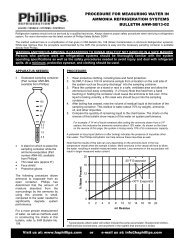
Step 1: Nozzle Sizing<br />
First correct the refrigeration capacity for the conditions in tables 1, 2 and 3 (if applicable). Divide the capacity by the fac<strong>to</strong>r in Table 1. Do<br />
the same for Tables 2 and 3. Select the nozzle from Table 4 that has a capacity equal <strong>to</strong> or greater than the adjusted capacity.<br />
15
Accessories<br />
Table 1a: R-717 Operating <strong>Co</strong>ndition <strong>Co</strong>rrection Fac<strong>to</strong>rs<br />
Suction<br />
<strong>Co</strong>ndensing Temperature<br />
Temperature 45°F 55°F 65°F 75°F 85°F 95°F 105°F<br />
40°F - 0.60 0.71 0.80 0.90 0.98 1.08<br />
-40°F <strong>to</strong><br />
+30°F<br />
0.61 0.69 0.77 0.85 0.93 1.00 1.09<br />
Table 1b: Halocarbon Operating <strong>Co</strong>ndition <strong>Co</strong>rrection Fac<strong>to</strong>rs<br />
Refrigerant<br />
Suction<br />
<strong>Co</strong>ndensing Temperature<br />
Temperature 70°F 80°F 90°F 95°F 100°F 110°F<br />
40°F 0.87 0.95 1.01 1.04 1.07 1.12<br />
20°F 0.86 0.92 0.98 1.00 1.03 1.07<br />
R-134a 5°F 0.83 0.89 0.94 0.96 0.98 1.02<br />
-10°F 0.80 0.85 0.90 0.91 0.93 0.97<br />
-40°F 0.72 0.77 0.81 0.82 - -<br />
40°F 0.93 0.98 1.02 1.04 1.04 1.05<br />
20°F 0.93 0.97 1.00 1.00 1.00 1.00<br />
R-404a 5°F 0.91 0.94 0.96 0.96 0.96 0.96<br />
-10°F 0.88 0.90 0.91 0.91 0.91 0.91<br />
-40°F 0.79 0.81 0.81 0.81 - -<br />
40°F 0.89 0.94 1.00 1.03 1.05 1.09<br />
20°F 0.87 0.93 0.97 1.00 1.02 1.04<br />
R-22 5°F 0.85 0.90 0.94 0.96 0.98 1.01<br />
-10°F 0.82 0.87 0.91 0.93 0.95 0.97<br />
-40°F 0.77 0.81 0.84 0.86 - -<br />
40°F 0.94 0.99 1.03 1.04 1.05 1.05<br />
20°F 0.93 0.97 1.00 1.00 1.00 1.00<br />
R-507a 5°F 0.92 0.95 0.96 0.96 0.96 0.96<br />
-10°F 0.88 0.90 0.91 0.91 0.91 0.91<br />
-40°F 0.79 0.80 0.80 0.80 - -<br />
Table 2: Subcooling <strong>Co</strong>rrection Fac<strong>to</strong>rs<br />
R-717 R-22 R-134a R-404a R-507a<br />
0ºF 1 1 1 1 1<br />
10ºF 1.33 1.23 1.31 1.21 1.21<br />
20ºF 1.56 1.41 1.53 1.38 1.38<br />
30ºF 1.74 1.55 1.7 1.51 1.51<br />
40ºF 1.87 1.66 1.83 1.62 1.61<br />
50ºF 1.98 1.75 1.94 1.7 1.7<br />
60ºF 2.06 1.82 2.02 1.77 1.77<br />
70ºF 2.13 1.87 2.09 1.83 1.82<br />
Table 3: Halocarbon Nozzles <strong>Co</strong>rrection Fac<strong>to</strong>rs<br />
R-134a R-22 R-507a R-404a<br />
Adjustment<br />
Fac<strong>to</strong>r<br />
0.82 1 0.82 0.74<br />
Example:<br />
R-507a, 10 TR, 100°F condensing, -10°F evaporating, sub-cooled <strong>to</strong> 70°F<br />
From Table 1b: <strong>Co</strong>nditions correcting fac<strong>to</strong>r = 0.91<br />
<strong>Co</strong>rrected <strong>to</strong>nnage = 10 TR/0.91 = 11 TR<br />
From Table 2: <strong>Co</strong>rrection fac<strong>to</strong>r for 30°F sub-cooling = 1.51<br />
<strong>Co</strong>rrected <strong>to</strong>nnage = 11 TR/1.51 = 7.3 TR<br />
From Table 3: Nozzle correction fac<strong>to</strong>r = 0.82<br />
<strong>Co</strong>rrected <strong>to</strong>nnage = 7.3 TR/0.82 = 8.9 TR<br />
From Table 4: Nozzle selection corresponding <strong>to</strong> 8.9 TR = #29<br />
Table 4: Nozzle Capacities (Tons)<br />
Nozzle # 59 56 54 52 50 48 44 40 36 31 29 23 16 7 1 1/4" 5/16"<br />
Orifice Dia .041” .047” .055” .064” .070” .076” .086” .098” .107” .120” .136” .154” .177” .201” .228” .250” .313”<br />
Approx. Cv 0.046 0.059 0.083 0.11 0.13 0.16 0.2 0.26 0.31 0.4 0.51 0.65 0.86 1.1 1.4 1.7 2.7<br />
Halocarbon 0.9 1.2 1.6 2.2 2.7 3.1 4 5.2 6.1 7.8 10 13 17 22 28 33 50<br />
Ammonia 3.9 5 7 9.3 11 13 17 22 26 33 43 55 72 93 120 140 220<br />
Step 2: Throat Selection<br />
For ammonia applications, select the throat with the adjusted capacity from Table 5. If it is a halocarbon application, adjust the capacity<br />
using Table 6 and select the throat from Table 7.<br />
Table 5: Ammonia Throat Capacities (Tons, 2:1 Circulating Rate)<br />
Suction<br />
Throat Size (in.)<br />
Temperature 3/16 1/4 5/16 3/8 1/2 5/8 3/4 1 1-1/4 1-1/2<br />
40ºF 4.8 12 20 28 50 78 110 200 310 449<br />
30 ºF 4.2 10 17 24 42 66 94 170 270 378<br />
20 ºF 3.4 8.8 14 20 35 54 79 140 220 315<br />
10 ºF 2.8 7 11 16 28 43 63 110 180 260<br />
0 ºF 2.2 5.6 9 13 23 35 51 90 140 210<br />
-10 ºF 1.8 4.6 7.4 11 19 29 42 75 120 170<br />
-20 ºF 1.4 3.6 5.4 8 14 22 32 57 90 130<br />
-30 ºF 1.1 2.6 4.2 6.2 11 17 24 43 69 100<br />
-40 ºF 0.8 2 3.4 4.6 8.2 13 19 33 53 80<br />
Table 7: Halocarbon Throat Capacities (Tons, 2:1 Circulating Rate)<br />
Suction<br />
Throat Size (in.)<br />
Temperature 3/16 1/4 5/16 3/8 1/2 5/8 3/4 1 1-1/4<br />
40ºF 2 3.6 5.7 8.2 15 23 33 57 -<br />
30 ºF 1.8 3.1 4.9 7.1 13 20 28 49 -<br />
20 ºF 1.5 2.6 4.1 5.9 11 16 24 42 -<br />
10 ºF 1.2 2.2 3.4 4.9 8.8 14 20 35 54<br />
0 ºF 1.1 1.9 3 4.3 7.7 12 17 30 45<br />
-10 ºF 0.9 1.6 2.5 3.6 6.4 10 14 25 37<br />
-20 ºF 0.8 1.3 2.1 3 5.4 8.4 12 21 32<br />
-30 ºF 0.6 1 1.6 2.3 4.2 6.5 9.4 17 26<br />
-40 ºF 0.5 0.8 1.3 1.8 3.2 5.1 7.4 13 20<br />
Table 6: Halocarbon Refrigerant Adjustment<br />
For Throats<br />
R-134a R-22 R-507a R-404a<br />
Adjustment<br />
Fac<strong>to</strong>r<br />
0.91 1 0.91 0.86<br />
Example (continued)<br />
From Table 6: Throat correction fac<strong>to</strong>r = 0.91<br />
<strong>Co</strong>rrected <strong>to</strong>nnage = 8.9 TR/0.91 = 9.8 TR<br />
From Table 7: Throat selection is 5/8”<br />
16
Accessories<br />
Step 3: Injec<strong>to</strong>r Body Style Selection<br />
Various combinations of nozzles and throats can be seen in Table 8. Injec<strong>to</strong>rs are available in four different families shown in Table 9.<br />
Using these two tables, the final injec<strong>to</strong>r selection can be made.<br />
Table 8: <strong>Co</strong>mmon Injec<strong>to</strong>r Nozzle & Throat Sizes*<br />
Nozzle Size<br />
59<br />
56<br />
54<br />
52<br />
50<br />
48<br />
44<br />
40<br />
36<br />
31<br />
29<br />
23<br />
16<br />
7<br />
1<br />
Throat Diameter (in.)<br />
3/16 1/4 5/16 3/8 1/2 5/8 3/4 1 1-1/4 1-1/2<br />
2020SL<br />
2075WCB<br />
2075WCB<br />
2020SL<br />
2075WCB<br />
2075WCB<br />
2020SL<br />
2100SL<br />
2075WCB<br />
2100SL<br />
2075WCB<br />
2020SL<br />
2100SL<br />
2075WCB<br />
2100WCB<br />
2100WCBA<br />
2100SL<br />
2075WCB<br />
2100 WCB<br />
2100WCBA<br />
2100SL<br />
2100WCB<br />
2100WCBA<br />
2100SL<br />
2100WCB<br />
2100WCBA<br />
2125WA<br />
2125WA<br />
2150WA<br />
2100SL<br />
2100WCB<br />
2100WCBA<br />
2100SL<br />
2100WCB<br />
2100WCBA<br />
2125WA<br />
2125WA<br />
2150WA<br />
1/4" 2150WA 2150WA 2150WA<br />
2150WA<br />
2200WA<br />
2200WA 2200WA<br />
5/16" 2200WA 2250WA 2250WA<br />
*This table lists only the most common nozzle and throat sizes. <strong>Co</strong>ntact <strong>Phillips</strong> if the size or combination of sizes you need is not listed.<br />
2100SL<br />
2100SL<br />
2125WA<br />
2100SL<br />
2125WA<br />
2150WA<br />
2125WA<br />
2150WA<br />
2150WA<br />
Table 9: Injec<strong>to</strong>r Families, Model Numbers and <strong>Co</strong>nnection Sizes<br />
High Pressure Low Pressure Mixed Liquid<br />
Family Model<br />
Liquid Inlet Liquid Inlet Outlet<br />
3/8" OD <strong>Co</strong>pper 3/4" OD <strong>Co</strong>pper 3/4"OD <strong>Co</strong>pper<br />
2020SL<br />
(1/4” Nominal) (5/8” Nominal) (5/8” Nominal)<br />
2000SL<br />
5/8" OD <strong>Co</strong>pper 1-3/8" OD <strong>Co</strong>pper 1-3/8"OD <strong>Co</strong>pper<br />
2100SL<br />
(1/2” Nominal) (1-1/4” Nominal) (1-1/4” Nominal)<br />
2075WCB 3/8" FPT 3/4” FPT 3/4” Butt Weld<br />
2100WCB 2100WCB 1/2” FPT<br />
1” FPT<br />
1” Butt Weld<br />
2100WCBA 5/8” OD <strong>Co</strong>pper 1” MPT<br />
2100WA<br />
2200WA<br />
1/2” FPT<br />
2125WA 1-1/4” Butt Weld 1-1/4” Butt Weld<br />
5/8” OD <strong>Co</strong>pper<br />
3/4” FPT<br />
2150WA 1” Butt Weld 1-1/2” Butt Weld 1-1/2” Butt Weld<br />
7/8” OD <strong>Co</strong>pper<br />
2200WA<br />
1/2” FPT<br />
3/4” FPT 2” Butt Weld 2” Butt Weld<br />
2250WA<br />
1-1/8” OD <strong>Co</strong>pper<br />
1” FPT<br />
1-3/8” OD <strong>Co</strong>pper<br />
2-1/2” Butt Weld 2-1/2” Butt Weld<br />
Example (continued)<br />
Injec<strong>to</strong>rs allowing #29 nozzle and 5/8” throat:<br />
• 2100SL<br />
• 2100WCB<br />
• 2100WCBA<br />
• 2125WA<br />
Refer <strong>to</strong> Table 9 and system piping <strong>to</strong> choose<br />
preferred body style.<br />
Plate and Frame Injec<strong>to</strong>r <strong>Co</strong>ntrol<br />
The <strong>Phillips</strong> injec<strong>to</strong>r may be applied <strong>to</strong> a “fixed” charge system or a “central” type system. Its application with a plate and frame unit allows<br />
for a smaller surge drum, thereby reducing operating cost, first cost, and maintenance cost. The cost savings in a “fixed” charge system are<br />
particularly advantageous because a liquid level control assembly is not required. The liquid level control assembly required for a “central<br />
system” installation may consist of either a <strong>Phillips</strong> float valve or a float switch with a solenoid valve. Multiple injec<strong>to</strong>rs may be employed<br />
<strong>to</strong> parallel plate and frame applications.<br />
The <strong>Phillips</strong> injec<strong>to</strong>r meters the liquid refrigerant from the system through the nozzle and is mixed with liquid refrigerant from the surge<br />
drum. This mix is introduced through the throat at a recirculated rate in<strong>to</strong> the plates for efficient operation. Sample selections for various<br />
plant sizes and operating conditions follow.<br />
17
Accessories<br />
Central Plant Application<br />
Fixed Charge Application<br />
Application<br />
Central<br />
Plant<br />
Capacity<br />
R-717<br />
(Tons)<br />
* Not required for fixed charge plants<br />
Injec<strong>to</strong>r<br />
Model<br />
Nominal<br />
Injec<strong>to</strong>r<br />
Size (in.)<br />
Level <strong>Co</strong>ntrol<br />
Model*<br />
(Central Plant)<br />
Vertical Surge Drum for<br />
Suction Temperatures (°F)<br />
Liquid<br />
Leg<br />
Suction Line size<br />
(in.) for Gas Return<br />
Diameter Temperatures (°F)<br />
+32 +10 -10 (in.) +32 +10 -10<br />
25 2075WCB 3/4 300H 10" X 42" 12" X 42" 12" X 42" 2-1/2 3 3 4<br />
50 2100WCB 1 301J 14" X 42" 16" X 42" 18" X 42" 3 4 4 5<br />
75 2125WA 1-1/4 301K 18" X 36" 20" X 40" 20" X 40" 3-1/2 5 5 6<br />
125 2150WA 1-1/2 300H, 701JRS 24" X 48" 24" X 48" 30" X 42" 4 5 6 6<br />
200 2200WA 2 300H, 701S 30" X 54" 30" X 54" 36" X 54" 5 6 8 8<br />
300 2250WA 2-1/2 300H, 701S 36" X 60" 36" X 60" 42" X 54" 6 8 8 10<br />
Note: This data represents typical application with warm high pressure liquid. <strong>Co</strong>nsult fac<strong>to</strong>ry for specific R-717 and halocarbon applications. Multiple injec<strong>to</strong>rs can be<br />
used for larger capacities.<br />
2020 and 2100 (Halocarbon Only) 2075, 2100, 2125, 2150, 2200, 2250<br />
(All Refrigerants)<br />
INJECTOR DIMENSIONS (in.)<br />
Dimensions (in.)<br />
Model<br />
Weight<br />
E<br />
F<br />
Number A B C D<br />
G H (lbs.)<br />
(IPS) (IPS) (ODC)<br />
2020SL 2.15 4.15 0.8<br />
1.31 2.00 3/4 0.69 3/8 - 0.50<br />
2020SLD * 5.78† 1.0<br />
2100SL 4.07 6.94 2.4<br />
1.94 2.88 1-3/8 1.00 5/8 - 0.75<br />
2100SLD * 9.09† 3.8<br />
2075WCB 2.13 3.63 6.38 0.99 3/4 (FPT) 3/8, 1/2 5/8 - - 2.15<br />
2100WCB 2.69 4.00 7.25 1.25 1 (FPT) 3/8, 1/2 5/8 - - 3.55<br />
2100WCBA 2.69 4.00 7.25 1.25 1 (MPT) 3/8, 1/2 5/8 - - 3.60<br />
2125WA 1.88 3.25 5.87 1.25 1-1/4 1/2 5/8 - - 4.15<br />
2150WA 2.25 3.94 7.38 1.44 1-1/2 3/4 7/8 - - 6.50<br />
2200WA 2.50 6.37 11.75 1.88 2 3/4 1-1/8 - - 11.38<br />
2250WA 3.00 6.31 12.50 2.31 2-1/2 1 1-3/8 - - 13.20<br />
* Variable-consult fac<strong>to</strong>ry<br />
†Maximum<br />
18
VB-12E-02<br />
www.haphillips.com<br />
770 Enterprise Avenue<br />
DeKalb, IL 60115<br />
P: 630-377-0050<br />
F: 630-377-2706