with LABCAR - HANSER automotive
with LABCAR - HANSER automotive
with LABCAR - HANSER automotive

You also want an ePaper? Increase the reach of your titles
YUMPU automatically turns print PDFs into web optimized ePapers that Google loves.
S PECIAL E DITION<br />
<strong>automotive</strong><br />
H A N S E R<br />
electronics systems<br />
© Carl Hanser Verlag, München www.hanser-<strong>automotive</strong>.de Nicht zur Verfügung im Intranet- und Internet-Angeboten sowie elektronischen Verteilern<br />
6<br />
FlexRay<br />
<strong>with</strong> <strong>LABCAR</strong><br />
FlexRay from first launch to a defacto standard · FlexRay Residual Bus Simulation<br />
on HiL Testing Systems· FlexRay Becomes Daily Routine · FlexRay Protocol Implementation<br />
Analysis – The Story · ECU Tests for FlexRay Applications · Easy access to FlexRay · Testing<br />
CAN and FlexRay Networks · FlexRay in AUTOSAR · Body and gateway microcontroller<br />
<strong>with</strong> embedded FlexRay · FlexRay Controller - Integrated or Discrete? · FlexRay Products
FLEXRAYl AUTOMOTIVE<br />
2007l3<br />
© Carl Hanser Verlag, München www.hanser-<strong>automotive</strong>.de Nicht zur Verfügung im Intranet- und Internet-Angeboten sowie elektronischen Verteilern<br />
FlexRay<br />
from first launch<br />
to a defacto<br />
standard<br />
The FlexRay consortium has<br />
already made two publicly<br />
released versions of the Flex-<br />
Ray specifications. Components are<br />
available, and parts designed for<br />
these applications are in use in a first<br />
application – the 2007 BMW X5<br />
variable damper suspension system.<br />
Several other applications are now<br />
under development by multiple<br />
OEMs.<br />
So the usage of FlexRay will heavily<br />
increase in the near future and there is<br />
absolutely no question that it has been<br />
a successful launch of a new communication<br />
standard and it’s on its way to<br />
becoming the defacto standard <strong>with</strong>in<br />
this domain.<br />
Peter Hansson, GM (Saab),<br />
is Consortium Speaker of the<br />
FlexRay Consortium<br />
One factor in the success of this launch has been the formal release of the<br />
conformance test suites for communication controllers and physical layer<br />
devices. Now semiconductor suppliers can design their silicon solutions to<br />
be confirmed and approved by the conformance test partners. This will<br />
enhance the interoperability and the overall system behavior of a FlexRay in<br />
vehicle architecture.<br />
Meanwhile the Consortium is maintaining both the protocol and the test specifications<br />
and is planning to introduce several enhancements. The main<br />
goals of the consortium and the driver of the development plan is to develop<br />
a new specification set by the end of the current consortium agreement.<br />
The consortiums work has been influenced by the input from other consortia<br />
such as Autosar and Jaspar and it has always been the ambition to strengthen<br />
these relationships. In 2007 the consortium has been working on forms<br />
and procedures to establish a closer cooperation and a first workshop meeting<br />
together <strong>with</strong> Jaspar delegates in conjunction <strong>with</strong> the FlexRay Product<br />
day. These activities are welcome initiatives to strengthen the standard and<br />
to limit the proliferation in this domain.<br />
The committance of OEMs, such as GM, to put FlexRay into series production<br />
guarantees for the success of FlexRay as a key building block <strong>with</strong>in the<br />
vehicle electrical architecture infrastructure.
4lA UTOMOTIVE 2004l<br />
CONTENT<br />
SPECIAL EDITION FLEXRAYl SPECIAL AUTOMOTIVE EDITION FLEXRAY<br />
2007<br />
© Carl Hanser Verlag, München www.hanser-<strong>automotive</strong>.de Nicht zur Verfügung im Intranet- und Internet-Angeboten sowie elektronischen Verteilern<br />
3 FlexRay from first launch to<br />
a defacto standard<br />
Preface by Peter Hansson, spokesperson for<br />
the FlexRay Consortium<br />
6 ETAS: FlexRay Residual Bus Simulation<br />
on HiL Testing Systems<br />
Vehicle dynamics ECUs <strong>with</strong> FlexRay communications are being<br />
tested on facilities equipped <strong>with</strong> <strong>LABCAR</strong> Hardware-in-the Loop<br />
systems<br />
10 Vector: FlexRay Becomes Daily Routine<br />
CANoe.FlexRay enables engineers to solve both routine and challenging<br />
FlexRay tasks<br />
13 Ertesis: FlexRay Protocol Implementation<br />
Analysis – The Story<br />
Finding implementation flaws was a really hard job until today.<br />
Now it will become common practice by stimulation <strong>with</strong> arbitrary<br />
FlexRay streams while simultaneously recording raw bus communication<br />
data.<br />
17 dSpace: ECU Tests for FlexRay Applications<br />
Test methods and restbus simulation<br />
21 TZM: Easy access to FlexRay<br />
Turn-key Platform for FlexRay rookies<br />
22 TTTech Automotive: Testing CAN and<br />
FlexRay Networks<br />
Portable Gateway Tool for Testing CAN and FlexRay Networks<br />
24 Fujitsu: FlexRay in AUTOSAR<br />
Solutions for both standard<br />
26 NEC: Body and gateway microcontroller<br />
<strong>with</strong> embedded FlexRay<br />
FlexRay evaluation board and AUTOSAR starter kit<br />
29 Infineon: FlexRay Controller -<br />
Integrated or Discrete?<br />
Engineers spoilt for choice<br />
32 Products<br />
42 masthead / index of advertisers<br />
29<br />
13<br />
Finding implementation flaws will<br />
become common practice by stimulation<br />
<strong>with</strong> arbitrary FlexRay streams while<br />
simultaneously recording raw bus<br />
communication data.<br />
At Robert Bosch Chassis Systems Control,<br />
vehicle dynamics ECUs <strong>with</strong> Flex-<br />
Ray communications are being tested<br />
on facilities equipped <strong>with</strong> <strong>LABCAR</strong><br />
Hardware-in-the Loop systems. While<br />
development engineers use the same<br />
systems for function and release<br />
testing, manufacturing deploys them<br />
for testing ECU warranty returns.<br />
What are the advantages for<br />
<strong>automotive</strong> system designers<br />
of using a discrete FlexRay<br />
communications controller<br />
and one integrated into its<br />
high end 32-bit microcontroller<br />
family.<br />
6
© Carl Hanser Verlag, München www.hanser-<strong>automotive</strong>.de Nicht zur Verfügung im Intranet- und Internet-Angeboten sowie elektronischen Verteilern
6lA UTOMOTIVE 2007l SPECIAL EDITION FLEXRAY<br />
© Carl Hanser Verlag, München www.hanser-<strong>automotive</strong>.de Nicht zur Verfügung im Intranet- und Internet-Angeboten sowie elektronischen Verteilern<br />
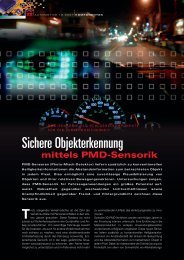
FlexRay Residual Bus Simulation<br />
on HiL Testing Systems<br />
At Robert Bosch Chassis Systems Control, vehicle dynamics ECUs<br />
<strong>with</strong> FlexRay communications are being tested on facilities equipped<br />
<strong>with</strong> <strong>LABCAR</strong> Hardware-in-the Loop systems. While development<br />
engineers use the same systems for function and release testing,<br />
manufacturing deploys them for testing ECU warranty returns.<br />
The HiL test bench simulates static and dynamic<br />
events occurring <strong>with</strong>in the DVE (driver, vehicle,<br />
environment) surroundings of the ECUs to be<br />
tested. This is accomplished by simulating the ECU environment<br />
through the use of electrical loads and a DVE<br />
model. HiL test benches provide a liberal degree of latitude<br />
for ECU testing that is both free of hazards and<br />
reproducible.<br />
Robert Bosch Chassis Systems Control deploys <strong>LABCAR</strong><br />
testing systems by ETAS, on which the DVE model runs in<br />
a real-time environment on a standard PC (<strong>LABCAR</strong>-RTPC).<br />
The I/O signals obtained from the ECU are exchanged <strong>with</strong><br />
the model in closed-loop fashion through dedicated interfaces<br />
in the <strong>LABCAR</strong> hardware. The attendant cycle times<br />
amount to a few milliseconds. With the aid of the <strong>LABCAR</strong>-<br />
OPERATOR software, the experiments can be controlled
SPECIAL EDITION FLEXRAYl AUTOMOTIVE<br />
2007l7<br />
© Carl Hanser Verlag, München www.hanser-<strong>automotive</strong>.de Nicht zur Verfügung im Intranet- und Internet-Angeboten sowie elektronischen Verteilern<br />
Figure 1:The virtual replication of bidirectional ECU communications and the linking<br />
to an implemented network subsystem is known as residual bus simulation.<br />
interactively by the user by means of a host computer.<br />
Another control option is the use of test automation.<br />
As a component of DVE simulation, residual bus simulation<br />
replaces non-existent physical ECUs <strong>with</strong> their simulated<br />
counterparts. Using an appropriate interface, the host computer<br />
running the simulation both transmits the signals of<br />
the virtual nodes via the data bus and receives messages<br />
from the ECU under test.<br />
The <strong>LABCAR</strong>-RTPC FlexRay interface<br />
Specifically for the purpose of FlexRay residual bus simulation<br />
on the <strong>LABCAR</strong>-RTPC, Electrobit (EB) formerly<br />
DECOMSYS has developed the EB5100 FlexRay-PCI Interface<br />
Board. Installed in the <strong>LABCAR</strong>-RTPC, this board converts<br />
the physical signals of the environment model to<br />
transport data types. The signals are packed in FlexRay frames,<br />
which are transmitted in accordance <strong>with</strong> predetermined<br />
timing information. The EB5100 module is also capable<br />
of receiving analog signals: Frame data is passed on to<br />
the model in the form of receiving FlexRay signals. In the<br />
subsequent calculation cycle, the model returns<br />
updated data to the FlexRay bus through the<br />
interface.<br />
To relieve the <strong>LABCAR</strong>-RTPC of the computation-intensive<br />
FlexRay communications<br />
task and, at the same time,<br />
decouple the model calculations<br />
from the FlexRay clock cycle, the<br />
EB5100 board employs a powerful<br />
MPC5200 PowerPC processor. This enables<br />
the board to handle all FlexRay communications,<br />
including scheduling tasks. In addition, the board handles<br />
system services, such as network management, or calculating<br />
the values of the Alive Counter and the Application<br />
CRC. To this end, the user can store calculation algorithms<br />
in mostly OEM-specific Target User Modules in a reserved<br />
area of the board’s firmware.<br />
The EB5100 board is equipped <strong>with</strong> two communications<br />
controllers. Using the E-Ray IP, these are programmed in an<br />
FPGA and are therefore easily<br />
up-dated. The data bus is connected<br />
by means of exchangeable<br />
driver modules (TJA1080<br />
by default).<br />
With the aid of the two communications<br />
controllers, Flex-<br />
Ray communications can be<br />
started and synchronized independently<br />
of the unit being<br />
tested. During a test, this also<br />
presents an easy way of switching<br />
back and forth between a<br />
virtual node being serviced by<br />
one of the controllers and a real<br />
system.<br />
By simulating the signals present<br />
onboard a vehicle, the<br />
© <strong>automotive</strong><br />
EB5100 board makes it possible<br />
to operate a FlexRay ECU<br />
on the testing system. In addition, it is possible to test ECU<br />
behavior during vehicle startup, while synchronizing bus<br />
communications, and in the event of a fault occur-rence.<br />
To this end, it is possible, on the one hand, to hide not only<br />
single frames but also entire bus nodes. On the other hand,<br />
the model’s full access to all of the signals, plus the target<br />
user modules, enables the generation of implausible<br />
values, e.g., those of sensors or checksums, and the subsequent<br />
observation of an ECU’s response to the same.<br />
The FlexRay module on the EB5100 board is manufactured<br />
to the PMC (PCI mezzanine card) standard. This makes it<br />
possible to adapt carrier boards for other backplane bus<br />
systems, such as compact PCI, PXI, or VME, to the module.<br />
As a result, Robert Bosch Chassis Systems Control can<br />
deploy the very same FlexRay residual bus simulation in<br />
other environments, such as endurance testing systems,<br />
for example.<br />
Figure 2:The EB5100 FlexRay interface board is<br />
a PMC-based module that is suitable for use<br />
<strong>with</strong> a variety of carrier boards.The<br />
EB5100 is equipped <strong>with</strong> two<br />
E-Ray communications<br />
controllers.
8lA UTOMOTIVE 2007l SPECIAL EDITION FLEXRAY<br />
© Carl Hanser Verlag, München www.hanser-<strong>automotive</strong>.de Nicht zur Verfügung im Intranet- und Internet-Angeboten sowie elektronischen Verteilern<br />
Configuring the<br />
FlexRay residual<br />
bus simulation<br />
The FlexRay residual bus simulation<br />
is configured in five steps.<br />
Step one requires the use of the<br />
EB Busmirror tool, which imports<br />
the communication matrix of the<br />
respective vehicle project in the<br />
FIBEX format. In addition to<br />
FIBEX version 2.0.1, the tool supports<br />
FIBEX+, providing AUTO-<br />
SAR-compliant processing of<br />
PDU signals. The Busmirror uses<br />
an extract from the FIBEX information<br />
to generate an XML file<br />
(FlexRay config-uration), which<br />
describes the avail-able FlexRay<br />
signals and application-specific<br />
data for the purpose of mapping<br />
the same to the model.<br />
Step two consists of mapping the<br />
Figure 3: <strong>LABCAR</strong> Hardware-in-the-Loop (HiL) test bench <strong>with</strong> FlexRay residual FlexRay signals to the signals of<br />
bus simulation.The intelligent FlexRay interface EB5100 is installed in the form of the <strong>LABCAR</strong> model. In step three,<br />
a PCI board in the real-time PC (<strong>LABCAR</strong>-RTPC) of the system performing the test. based on the mapping rule and<br />
The <strong>LABCAR</strong>-OPERATOR software running on the host computer comprises the the FlexRay configuration, a C<br />
user interface of the HiL system.The EB Busmirror tool configures both residual module containing the attendant<br />
bus simulation and EB5100 interface board.<br />
variables is generated. It renders<br />
© <strong>automotive</strong> FlexRay communications manipulable<br />
and integrates them <strong>with</strong><br />
the DVE model. At Robert<br />
Bosch Chassis Systems<br />
Control, the C modules<br />
are held in a central database;<br />
after a quality assurance<br />
procedure, they are<br />
available for use by all<br />
<strong>LABCAR</strong> test benches. In<br />
step four, the configuration<br />
for the target user<br />
modules of the EB5100<br />
board, such as Alive<br />
Counter, Application CRC,<br />
or Network Management,<br />
are generated on<br />
the basis of the FlexRay<br />
configuration in accordance<br />
<strong>with</strong> user specifications.<br />
To support steps<br />
one through four, Robert<br />
Figure 4: Decoupled timing between the model simulation on the <strong>LABCAR</strong>-RTPC and the Bosch Chassis Systems<br />
FlexRay communication cycle.The EB5100 FlexRay interface board runs in synch <strong>with</strong> the Control has developed<br />
FlexRay clock cycle. Independently of the same, the <strong>LABCAR</strong>-RTPC handles the calculations proprietary Perl tools. In<br />
of the environment model on the basis of the control cycle.The FlexRay signals are transferred<br />
through an intermediate memory. In the event that future applications re-quire the exeror<br />
uses the configuration<br />
step five, the EB Busmircution<br />
of the model in synch <strong>with</strong> the FlexRay cycle, the time base of the EB5100 board files for the Target User<br />
may be made available to the <strong>LABCAR</strong>-RTPC and passed on to the HiL computer.<br />
Modules in conjunction<br />
© <strong>automotive</strong> <strong>with</strong> the FIBEX data to<br />
generate the firmware for
© Carl Hanser Verlag, München www.hanser-<strong>automotive</strong>.de Nicht zur Verfügung im Intranet- und Internet-Angeboten sowie elektronischen Verteilern<br />
FLEXRAYl AUTOMOTIVE 2007l 9<br />
the EB5100 board. If required, this step can be preceded<br />
by the manual shifting of FlexRay frames between the two<br />
FlexRay controllers. It is also possible to correct any data in<br />
the FIBEX file that was found to be incomplete or faulty.<br />
Deployment in production<br />
FlexRay residual bus simulation is already successfully<br />
deployed on Robert Bosch Chassis Systems Control’s<br />
<strong>LABCAR</strong> test benches in several customer projects. The<br />
FlexRay integration fulfills Robert Bosch Chassis Systems<br />
Control’s expectations of a flexibly configurable HiL<br />
system: The FlexRay interface is fully integrated <strong>with</strong> the<br />
<strong>LABCAR</strong>-RTPC. It encapsulates the FlexRay communications<br />
and enables access to all FlexRay signals at runtime.<br />
The configuration for the residual bus simulation can be<br />
generated from the communication matrix by means of a<br />
consistent tool suite and made centrally available. If test<br />
automation is required, the parameterized model integration<br />
of FlexRay communications can be used to control the<br />
residual bus simulation.<br />
Deployment as a standard product<br />
ETAS – as the expert for HiL testing systems, and Elektrobit<br />
(EB) formerly DECOMSYS – as the pioneer of FlexRay technology,<br />
will jointly market the FlexRay residual bus simulation<br />
for <strong>LABCAR</strong> testing systems as a combined solution.<br />
The cooper-ation of both partners is based on the commitment<br />
to two key objectives that will characterize the jointly<br />
produced solution: the first being „best in class“ in terms of<br />
function-ality, and the second calling for extremely userfriendly<br />
operation. In this way, the user is relieved of the need<br />
to pay attention to the details of FlexRay communications<br />
and is able to fully focus on the testing task at hand.<br />
Dipl.-Ing. (FH) Alexander Bayerl<br />
Alexander Bayerl studied communications<br />
engineering at the University of Applied<br />
Sciences in Esslingen. He entered the Robert<br />
Bosch GmbH in 1999. Alexander Bayerl is<br />
designing engineer in the <strong>LABCAR</strong> team and<br />
responsible for the specification and integration<br />
of the FlexRay component.<br />
Dipl.-Ing. Florian Wandling<br />
Florian Wandling studied Electrical Engineering<br />
at the Vienna University of Technology. He<br />
gained international experience in Dubai, Jakarta,<br />
and Manila during his studies. Florian<br />
Wandling is Product Manager for measurement,<br />
analysis, and testing tools at Elektrobit<br />
(EB) formerly DECOMSYS.<br />
Dr. Ulrich Wolters<br />
Dr. Ulrich Wolters studied Physics at the University<br />
of Bochum. He earned his doctorate<br />
<strong>with</strong> a thesis about „Non linear wave phenomena<br />
in ECR mirror discharges“ (plasma<br />
physics). Dr. Wolters is Strategic Marketing<br />
Manager for Test and Validation at ETAS<br />
GmbH.<br />
Right away –<br />
<strong>with</strong> FlexRay!<br />
DTS and EDICflex –<br />
the perfect solution for diagnostics and<br />
flash programming of FlexRay ECUs<br />
No matter whether in development, validation<br />
or production – EDICflex hardware interfaces<br />
allow reliable ECU communication at any time.<br />
The Embedded Diagnostic Module guarantees<br />
robust realtime behaviour in diagnostic and<br />
flash programming applications.<br />
Benefit from DTS solutions also in your<br />
applications – flexible user interfaces and<br />
automation APIs are ready for you.<br />
Contact us now!<br />
Tel.: +49 (89) 456 56 420, www.softing.com
10lA UTOMOTIVE 2007l SPECIAL EDITION FLEXRAY<br />
© Carl Hanser Verlag, München www.hanser-<strong>automotive</strong>.de Nicht zur Verfügung im Intranet- und Internet-Angeboten sowie elektronischen Verteilern<br />
FlexRay<br />
Becomes Daily Routine<br />
More and more engineers are nowadays confronted in their daily<br />
job <strong>with</strong> new challenges and tools required by the introduction of<br />
FlexRay as a new bus system for <strong>automotive</strong> applications. This article<br />
shows how engineers successfully meet the challenges of analyzing,<br />
simulating, and testing FlexRay ECUs and networks using<br />
CANoe.FlexRay from Vector.<br />
During the development of FlexRay ECUs and<br />
systems, engineers commonly encounter challenging<br />
tasks such as startup simulation, ECU<br />
tests and network simulation. This article describes how<br />
CANoe.FlexRay is already enabling FlexRay engineers<br />
to efficiently perform these tasks in a routine way.<br />
Startup Simulation<br />
A synchronized bus is a major requirement for a FlexRay<br />
communication. Before the application can communicate,<br />
the bus must be started. During this startup phase the bus<br />
is in an asynchronous mode until at least two ECUs have<br />
synchronized their FlexRay clocks and provide sync frames<br />
CANOE.FLEXRAY ENABLES ENGINEERS<br />
TO SOLVE BOTH ROUTINE AND<br />
CHALLENGING FLEXRAY TASKS<br />
so that other ECUs can integrate into the TDMA (Time Division<br />
Multiple Access) schedule. If the FlexRay communication<br />
of a single non-startup/sync ECU is being tested,<br />
then the analysis tool needs to be able to simulate a Flex-<br />
Ray bus that has already started. CANoe.FlexRay can generate<br />
two startup/sync frames in order to provide this type<br />
of startup of a FlexRay bus. The startup phase of a cluster<br />
can be observed using the asynchronous mode of Vector’s<br />
FlexRay interfaces VN3300 (PCI), VN3600 (USB) or VN7600<br />
(USB <strong>with</strong> CAN interfaces). It is possible for example to<br />
receive wakeup pattern, symbols, startup and normal frames<br />
before the cluster is in synchronous mode. The bus<br />
can also be analyzed in this mode <strong>with</strong>out using a FIBEX
SPECIAL EDITION FLEXRAYl AUTOMOTIVE<br />
2007l11<br />
© Carl Hanser Verlag, München www.hanser-<strong>automotive</strong>.de Nicht zur Verfügung im Intranet- und Internet-Angeboten sowie elektronischen Verteilern<br />
database. Only the baud rate is required in<br />
order to initialize the bus interface. To startup<br />
a sleeping cluster, wakeup pattern and<br />
symbols can be sent. The synchronous<br />
mode is the default mode, in which frames<br />
can be sent. The asynchronous and synchronous<br />
modes can also be combined so<br />
that the interface changes its mode automatically<br />
according to the clock synchronization<br />
state giving FlexRay engineers full<br />
analysis and simulation features at all<br />
times.<br />
ECU Test by Stimulation<br />
The easiest way of testing an ECU is to<br />
send frames interactively using CANoe’s FlexRay Frame<br />
Panel. Using this integrated panel a FlexRay frame’s payload<br />
(i.e. its signals) can be interactively modified during runtime.<br />
Signals for all bus systems can be modified via userdefined<br />
Control Panels. Using Signal Generators it is also<br />
possible to change a signal’s value according to predefined<br />
functions. For more advanced signal generation (e.g. arbitrary<br />
signal sequences or reactions to previous responses)<br />
the programming language CAPL should be used. Using<br />
the Test Feature Set of CANoe automated ECU tests can<br />
be defined, executed, and reported.<br />
ECU Test by Observation<br />
During the development of any real ECU it is crucial to guarantee<br />
that the ECU communicates in conformance <strong>with</strong><br />
FlexRay’s schedule table. Especially for frames in the static<br />
segment a periodically time-triggered transmission is<br />
assumed. CANoe can directly test and visualize whether<br />
all expected frames (according to their Cycle Multiplexing)<br />
of a specific ECU (sender) are on the bus. This feature is<br />
implemented in CANoe.FlexRay as the FlexRay Cluster<br />
Monitor. It helps engineers to identify the following:<br />
■ Which nodes are online and sending?<br />
■ Are all specified frames sent by a specific node?<br />
■ Are the frames sent in all scheduled cycles?<br />
Figure 2:The Cluster Monitor for displaying the send conformity<br />
of FlexRay nodes and their messages<br />
© <strong>automotive</strong><br />
Figure 1:The FlexRay Frame Panel makes it easy to interactively send<br />
FlexRay frames<br />
© <strong>automotive</strong><br />
The Cluster Monitor can also be used in offline mode to<br />
analyze log files. More extensive tests can be implemented<br />
in the programming language CAPL (also for the offline<br />
analysis).<br />
ECU Test by Simulation<br />
In order to test the functional behavior of any real ECU, its<br />
environment must be simulated. The system or device<br />
under test is usually embedded into a (Hardware-in-the-<br />
Loop) simulation. A minimal remaining bus simulation<br />
generates input frames and reacts to output frames from<br />
the ECU under test. Optionally an environment model can<br />
be simulated, which generates sensor inputs and reacts to<br />
actuator outputs. A simple example would be a model of a<br />
discrete and interactive user panel. In more complex cases<br />
a quasi-continuous control algorithm (e.g. defined by Matlab/Simulink)<br />
may be executed under the control of CANoe.<br />
Due to the time-triggered communication according to a<br />
global FlexRay time, the algorithms for the simulated controllers<br />
and ECUs must be synchronized <strong>with</strong> the FlexRay<br />
schedule. The execution platform must therefore provide<br />
synchronization points, guarantee small latencies as well<br />
as constant and minimal jitters. This guarantees to provide<br />
timely correct data updates on the bus. For the environment<br />
or remaining bus simulation the execution platform<br />
must be deterministic. CANoe RT, along <strong>with</strong> its hardware<br />
extensions RT Box and RT Rack, provides such a high performance<br />
and deterministic platform.<br />
CANoe and CANoe RT and their hardware<br />
extensions can be seamlessly scaled to<br />
meet the desired performance as well as<br />
the number of required bus and I/O interfaces.<br />
For both CANoe and CANoe RT the<br />
same (simulation) models can be used.<br />
Cluster Simulation<br />
In the early design phases of a FlexRay<br />
system it is important to test whether the<br />
timings are correct and/or the performance<br />
of an ECU matches the communication<br />
schedule. In other words, to check whether<br />
all frames can be received and transmitted<br />
in the reserved time. The FlexRay<br />
engineer therefore typically creates a (par-
12lA UTOMOTIVE 2007l SPECIAL EDITION FLEXRAY<br />
© Carl Hanser Verlag, München www.hanser-<strong>automotive</strong>.de Nicht zur Verfügung im Intranet- und Internet-Angeboten sowie elektronischen Verteilern<br />
Figure 3: CANoe RT is a real-time capable and deterministic execution platform<br />
tial) remaining bus simulation by adding a FIBEX database<br />
to CANoe.FlexRay and by defining the nodes required for<br />
the system under test. The CANoe.FlexRay’s features<br />
allow the full bus load, which is generated by all ECUs of a<br />
cluster, to be simulated. The communication matrix and the<br />
FlexRay schedule in the FIBEX database are used to configure<br />
the simulation of all required ECUs. All frames are<br />
automatically sent on the bus <strong>with</strong> default values. With Vector’s<br />
interfaces the theoretical maximum frame throughput<br />
can be sent <strong>with</strong>out running into resource problems (e.g.<br />
lack of send buffers). In this way all FlexRay ECUs can be<br />
simulated using only one tool and one bus interface.<br />
FlexRay offers direct support of network management and<br />
sleep/wakeup functionality. The bus transceivers of the<br />
Vector hardware interfaces can be switched to sleep mode<br />
in order to simulate a power off node. In this case only a<br />
wakeup pattern is received. Wakeup patterns can be sent<br />
in order to wake up a sleeping cluster. Using a special<br />
extension to CANoe.FlexRay, any simulated node can participate<br />
at the network management layer according to the<br />
AUTOSAR-NM protocol.<br />
© <strong>automotive</strong><br />
Gateway Simulation<br />
Gateways are used to transfer messages/frames/signals<br />
between two or more buses. CAN/FlexRay-gateways are<br />
typically unavoidable when FlexRay is implemented for<br />
automobiles based on CAN. As a multi-bus tool for CAN,<br />
LIN, MOST, and FlexRay, CANoe is capable of both simulating<br />
and analyzing gateway applications.<br />
A virtual gateway can also be used to simulate errors in the<br />
communication between ECUs. The device under test is<br />
isolated from the real bus by a FlexRay-FlexRay-gateway<br />
that is simulated by CANoe. Errors can be integrated by<br />
manipulating signals that are sent by the real ECUs. Optionally<br />
the two FlexRay clusters can be synchronized. Synchronously<br />
running clusters guarantee minimal delays between<br />
the signal occurrences on both buses.<br />
Summary<br />
All these application scenarios occur during the routine<br />
work of engineers developing FlexRay products.<br />
CANoe.FlexRay is a powerful tool to help engineers in their<br />
everyday work when handling the new technical challenges<br />
of FlexRay buses. CANoe is the flagship of Vector’s<br />
comprehensive portfolio of tools and embedded software<br />
components which are ready for both current and future<br />
FlexRay applications.<br />
Gavin C. Rogers B.Eng. M.Sc. is Team<br />
Manager in the “Tools for Networks and<br />
Distributed Systems” product line.<br />
Dr. rer. nat. Carsten Böke is Senior Software<br />
Development Engineer for the<br />
“Tools for Networks and Distributed<br />
Systems” product line.
SPECIAL EDITION FLEXRAYl AUTOMOTIVE<br />
2007l13<br />
© Carl Hanser Verlag, München www.hanser-<strong>automotive</strong>.de Nicht zur Verfügung im Intranet- und Internet-Angeboten sowie elektronischen Verteilern<br />
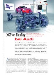
FlexRay Protocol<br />
Implementation<br />
Analysis –<br />
The Story<br />
Finding implementation flaws was a<br />
really hard job until today. Now it<br />
will become common practice by stimulation<br />
<strong>with</strong> arbitrary FlexRay<br />
streams while simultaneously recording<br />
raw bus communication data.<br />
Background story<br />
FlexRay is becoming a new standard in <strong>automotive</strong> bus<br />
communication, most notably because of the early commitment<br />
from leading car manufacturers. Lots of manyears<br />
of electronic engineering was spent to develop all the<br />
specifications and to bring FlexRay on the road. FlexRay<br />
nevertheless is still a young and not yet a fully mature protocol<br />
<strong>with</strong> some ten years of experience.<br />
During our consulting and engineering <strong>with</strong> FlexRay some<br />
time ago, we observed sporadic frame errors in a communication<br />
setup <strong>with</strong> a beta version microcontroller <strong>with</strong> an<br />
integrated FlexRay controller. But what was the reason for<br />
these errors? According to our understanding, we ourselves<br />
probably had transmitted a misplaced frame at some<br />
special point in time, what this beta type controller inside<br />
the other node must have disliked a lot. Could it maybe<br />
even be a poor implementation of the FlexRay specification<br />
which has led to this behaviour? But how should we<br />
find this problem, if it’s really present? A lot of questions<br />
still to answer...<br />
Prerequisites<br />
First, we had to check the requirements for an analysing<br />
system to discover this kind of problem. We agreed that<br />
we must be able not only to receive but also to send frames<br />
simultaneously and synchronously <strong>with</strong> the FlexRay<br />
communication. Furthermore it must be possible to completely<br />
control the bus start-up behaviour as the problem<br />
seemed to be related <strong>with</strong> it. It would also be advantageous,<br />
if the system could be able to receive and store all the<br />
bus data, which means in our application the whole Flex-<br />
Ray raw bit stream for detailed debugging purposes later<br />
on. Most of today’s analyzer systems do rely on standard<br />
FlexRay communication controllers, where the protocol<br />
engine let pass only payload data and filters header information<br />
or symbols.<br />
Ertesis already had developed a basic FlexRay analyzing<br />
system, which we could extend and adapt to the actual<br />
needs. The analyzer was based on an FPGA development<br />
board. This embedded system was connected to a PC by<br />
Ethernet, where a simple control and display software in<br />
Java was running. The system already could sample Flex-<br />
Ray data, transfer it to the PC and show it in a table style<br />
window. Sending a simple FlexRay frame in an asynchronous<br />
way was possible, too. We decided to use this setup<br />
as the base for our further development (Figure 1).<br />
Improving the design<br />
Now as we had reviewed our existing hardware and software<br />
and identified all the requirements for the enhanced<br />
FlexRay test system, we started the upgrading. The heart<br />
of our system is an own FlexRay controller core IP, which
14lA UTOMOTIVE 2007l SPECIAL EDITION FLEXRAY<br />
© Carl Hanser Verlag, München www.hanser-<strong>automotive</strong>.de Nicht zur Verfügung im Intranet- und Internet-Angeboten sowie elektronischen Verteilern<br />
Figure 1: System setup for testing the faulty node<br />
© <strong>automotive</strong><br />
we extensively upgraded to fulfil all the requirements mentioned<br />
before. A main issue was the start-up control. We<br />
wanted to completely manage the way the bus communication<br />
starts. All three start-up modes of the specification<br />
were implemented: coldstart node, following coldstart<br />
node and non-coldstart node. Beyond these modes, two<br />
arbitrary start-up modes have been integrated: force leading<br />
coldstart node and two-nodes coldstart, where the<br />
FlexRay controller core is able to start-up the bus communication<br />
on its own <strong>with</strong>out any further coldstart nodes.<br />
Therefore we did not need to use any additional FlexRay<br />
controller like a MFR4300 for start-up.<br />
The implementation of offset and rate correction algorithms<br />
is essential for synchronously sending true FlexRay<br />
frames on the bus. They have been adapted and accelerated<br />
to be able to send frames already during the coldstart<br />
collision resolution phase, just where we assumed to locate<br />
the error. Correct sending has been<br />
verified <strong>with</strong> different low level parameter<br />
sets.<br />
The FlexRay controller not only samples<br />
all bus data like frames, glitches and even<br />
symbols, but also transfers this data stream<br />
to the PC to immediately display it<br />
and to store it on hard disk for later offline<br />
analysis. Simultaneously, the controller<br />
is recording high precision timestamps<br />
straight at the signal input of the<br />
Rx and RxEN pins. A main timestamp<br />
<strong>with</strong> 48-bit is stored for each frame or<br />
event. Due to the resolution of 12.5 ns<br />
this would result in a wrap around time<br />
span of about forty days. Incidentally,<br />
these high resolution recordings allow for<br />
measurement of the dynamic characteristics<br />
of FlexRay transceivers, for example<br />
idle detection times. Figure 2 shows an Rx delay between<br />
163 and 175 ns witch is in the proper range from 100 to 250<br />
ns as specified in the transceiver datasheet. Further important<br />
information of every frame, like main timestamp, TSS<br />
length in ns, frame length in bits, cycle number and frame<br />
ID is displayed.<br />
Finding the flaws<br />
Finally we finished our analyzer and synthesizer system for<br />
the planned debugging attempt. We connected the suspicious<br />
FlexRay node to our hardware and recorded its standalone<br />
communication first. As supposed, the node performed<br />
its coldstart attempts in slot 1 correctly. After the<br />
system was programmed as a following coldstart node,<br />
communication again started <strong>with</strong>out any problems. Even<br />
<strong>with</strong> the system node being set up in two-nodes startup,<br />
the other node has integrated itself seamlessly. We knew<br />
that the problem probably must be located somewhere in<br />
the start-up phase, so we tried to disturb the coldstart of<br />
the node. Amongst different frames, we sent a synthesized<br />
frame in slot 3 in cycle 3, one cycle to early during the<br />
coldstart collision resolution phase of the node.<br />
We got it! The following frame coming from the system<br />
node, which was indeed completely correct, has been<br />
destroyed by the node (Figure 2). The disruption was caused<br />
by a CAS signal being sent during the frame transmission<br />
of the system node in slot 3, followed by a startup<br />
frame shortly later. This has drawn the bus level to a low<br />
signal.<br />
But why has it happened? We dug through the SDL charts<br />
of the FlexRay specification to find an answer for this faulty<br />
behaviour. We finally found a suspicious timer tStartup,<br />
which could be the culprit (Figure 3). If, for some reason,<br />
this timer is not correctly reset to its default value by<br />
reset(tStartup) after its expiration in the COLDSTART_<br />
LISTEN state, it could be possible, that by the second entry<br />
into the COLDSTART_LISTEN state due to entering the<br />
ABORT_STARTUP state before, no waiting is performed,<br />
but immediately a new cold start attempt headed by a CAS<br />
symbol would be executed.<br />
Figure 2:Table view of the Java control application showing coldstart<br />
symbols and destroyed frame in cycle 3<br />
© <strong>automotive</strong>
SPECIAL EDITION FLEXRAYl AUTOMOTIVE<br />
2007l15<br />
© Carl Hanser Verlag, München www.hanser-<strong>automotive</strong>.de Nicht zur Verfügung im Intranet- und Internet-Angeboten sowie elektronischen Verteilern<br />
Next task was to proof this theory. If the reason really<br />
is an incorrect or missing reset of the timer tStartup,<br />
there should be other paths and states leading to<br />
the same immediate second coldstart attempt. One<br />
of such other state is the COLDSTART_CONSISTEN-<br />
CY_CHECK state. If no other or an invalid startup<br />
frame is detected, the COLDSTART_ GAP is entered.<br />
If a valid header would be received during this gap,<br />
the ABORT_STARTUP state is entered. The following<br />
entry of the COLDSTART_ LISTEN state <strong>with</strong> already<br />
expired and not reset timer should then lead to an<br />
immediate coldstart attempt as well. We checked this<br />
by setting up a following coldstart transmission scheme,<br />
including a cycle 4 <strong>with</strong> a bit-flip to make it invalid<br />
followed by a correct cycle 5.<br />
Bingo! Node 2 destroyed our cycle 5 again <strong>with</strong> a CAS<br />
and a startup frame (Figure 4). With the FlexRay analyzer<br />
and synthesizer system, we could successfully<br />
prove that the timer tStartup is not correctly reset to<br />
its default value after expiration which effectively<br />
means an implementation flaw. qed.<br />
Figure 3: Entering COLDSTART_LISTEN state <strong>with</strong> expired timer<br />
tStartup leads to faulty behaviour<br />
Accomplishing further<br />
enhancements<br />
The development of Ertesis’ FlexRay system is still ongoing<br />
an recently, the company improved some very helpful<br />
features. One of them is an external signal output to trigger<br />
oscilloscopes on cycle starts, frame starts and other<br />
typical FlexRay events. With the new hardware trigger output,<br />
it is now possible to use existing oscilloscopes, rather<br />
then to buy a new and expensive one, only because of<br />
© <strong>automotive</strong>
16lA UTOMOTIVE 2007l SPECIAL EDITION FLEXRAY<br />
© Carl Hanser Verlag, München www.hanser-<strong>automotive</strong>.de Nicht zur Verfügung im Intranet- und Internet-Angeboten sowie elektronischen Verteilern<br />
Figure 4: Faulty node sending his CAS and frame in slot 3 of system node, destroying<br />
bus communication<br />
being engaged in a FlexRay project. The second very helpful<br />
feature is the shift frame functionality. It is easily possible<br />
to shift a frame post or past its original action point in<br />
micro tick resolution, completely controlled by the use of<br />
the GUI. The action point could of course be shifted over<br />
the slot boundaries.<br />
Gearing up to new horizons<br />
All this functionality and features tends us to the decision<br />
to redesign the FlexRay Analyzer and Synthesizer system<br />
to be more powerful and that it could also be used as an<br />
Automotive Development Platform<br />
(Figure 5). It is based on the latest<br />
Cyclone FPGA family, surrounded<br />
by peripheral devices and physical<br />
interfaces. Special attention was<br />
given to the cost / performance<br />
ratio. A soft core CPU serves as<br />
main processor. Additional hardware<br />
e.g. an <strong>automotive</strong> optical<br />
Ethernet module can be connected<br />
through two Santa Cruz compliant<br />
expansion ports. The in-system<br />
reconfigurability of the platform is<br />
the key to easy and quick updates<br />
and even upgrades.<br />
© <strong>automotive</strong> Together <strong>with</strong> FlexRay modules<br />
based on the Freescale S12XF<br />
microcontroller, Ertesis is capable<br />
of providing a complete portfolio of hardware and software<br />
tools for easy and successful FlexRay deployment.<br />
Dr.-Ing. Gregor Burmberger<br />
has been involved <strong>with</strong> FlexRay for many<br />
years. His team and he are developing engineering<br />
tools for <strong>automotive</strong> electronics<br />
besides consulting the <strong>automotive</strong> industry.<br />
He is the founder of ERTESIS, Germany.<br />
Figure 5: Block diagram of the FlexRay Analyzer and Synthesizer and the Automotive<br />
© <strong>automotive</strong>
SPECIAL EDITION FLEXRAYl AUTOMOTIVE<br />
2007l17<br />
© Carl Hanser Verlag, München www.hanser-<strong>automotive</strong>.de Nicht zur Verfügung im Intranet- und Internet-Angeboten sowie elektronischen Verteilern<br />
ECU Tests for<br />
FlexRay Applications<br />
The projects planned for introducing FlexRay in future vehicle series require<br />
powerful test systems. These will allow the functional and electrical behavior<br />
of the FlexRay systems to be tested comprehensively at an early<br />
stage. One important testing method is restbus simulation, in which one or<br />
more electronic control units (ECUs) are validated in conjunction <strong>with</strong> complex<br />
simulation models. dSPACE offers a comprehensive range of solutions<br />
for this - solutions that are proven in practice and also undergoing constant<br />
further development.<br />
Test Methods for FlexRay Applications<br />
Restbus simulation is a proven method for testing a system<br />
consisting of networked ECUs. The available real ECUs are<br />
connected to a simulator via the FlexRay bus. The simulator<br />
uses substitute models for virtual representation of the<br />
missing bus nodes. Plant models, e.g., for vehicle dynamics<br />
or specific vehicle assemblies, and recorded measurement<br />
data can be simulated and used in conjunction <strong>with</strong><br />
the substitute models in real time. The simulator sends the<br />
values output by the models to the real nodes, where they<br />
are available as input values. There are two forms of restbus<br />
simulation, static and dynamic:<br />
- Static restbus simulation involves a simple test structure<br />
in which the simulator generates synthetic messages as<br />
stimulus data and sends them to the real ECUs. These<br />
messages are independent of any simulated environment.<br />
- Dynamic restbus simulation gives the messages current<br />
values from detailed substitute and plant models. This generally<br />
requires powerful simulator hardware.<br />
A restbus simulation is derived from an existing communication<br />
matrix in FIBEX file format. Optimally, this step<br />
should be supported by development tools so that varying<br />
combinations of the ECUs under test can be put into operation<br />
flexibly. Partial automation of the restbus simulation
18lA UTOMOTIVE 2007l SPECIAL EDITION FLEXRAY<br />
© Carl Hanser Verlag, München www.hanser-<strong>automotive</strong>.de Nicht zur Verfügung im Intranet- und Internet-Angeboten sowie elektronischen Verteilern<br />
helps to reduce the configuration<br />
work associated <strong>with</strong> FlexRay, particularly<br />
for different integration stages<br />
of the ECU network. Finally, it is<br />
useful to express the substitute models<br />
in MATLAB/Simulink, i.e.,<br />
using the same modeling language<br />
as is most widely used for plant and<br />
function models.<br />
The basic structure of the test systems<br />
used should be proven in<br />
practice. The systems must be scalable<br />
and extendable and also have<br />
sufficiently high processing power<br />
even for large restbus and hardware-in-the-loop<br />
(HIL) simulation.<br />
This necessitates tight time coupling<br />
between the simulator and the<br />
FlexRay bus, plus real-time-capable<br />
message generation and processing,<br />
including the manipulation of<br />
messages to simulate error cases.<br />
In addition, the simulators should<br />
have an identical operating concept<br />
for each extension phase, from function testing to component<br />
and subsystem testing, right through to final network<br />
testing of overall system integration.<br />
ECU Tests <strong>with</strong> the<br />
dSPACE Solution for FlexRay<br />
Test systems from dSPACE meet the above requirements.<br />
Over the past few years, these have been systematically<br />
prepared as a FlexRay solution and are now successfully in<br />
use under real-world conditions.<br />
Figure 2: User interface of the dSPACE FlexRay Configuration Tool<br />
Figure 1: Workflow <strong>with</strong> dSPACE’s FlexRay solution.<br />
© <strong>automotive</strong><br />
Hardware Platforms for the Simulations<br />
All systems offered by dSPACE can be used as hardware<br />
platforms:<br />
- MicroAutoBox as the compact platform for function and<br />
component testing at a developer workstation. The Micro-<br />
AutoBox can be used <strong>with</strong> two FlexRay controllers, which<br />
enables it to start a FlexRay network. There is driver support<br />
for the Bosch E-Ray and also for the Freescale MFR<br />
4310 FlexRay Controller; the latter is available as a dSPACE<br />
DS4340 FlexRay Interface Module.<br />
- Numerous dSPACE Simulators Mid-Size<br />
have been shipped as component and<br />
subsystem testing stations. An interface<br />
board <strong>with</strong> slots for up to four FlexRay<br />
controllers can be installed in these simulators.<br />
This allows very flexible use scenarios<br />
<strong>with</strong>in restbus simulation.<br />
- Networked dSPACE Simulators Full-Size<br />
are frequently used to set up network<br />
tests for overall system integration. The<br />
same interface concept is used for Flex-<br />
Ray here, in the form of a carrier board for<br />
pluggable FlexRay controller modules.<br />
© <strong>automotive</strong><br />
Workflow for Configuring a<br />
Test System<br />
The workflow for configuring a test system<br />
is shown in Fig.1. In the dSPACE<br />
FlexRay Configuration Tool, the user selects<br />
from the data in a FIBEX file the communication<br />
elements that need to be available<br />
on the simulator (see Fig. 2). For<br />
example, these could be all frames that<br />
are sent by a virtual ECU represented on<br />
the simulator. Selecting these cases ge-
SPECIAL EDITION FLEXRAYl AUTOMOTIVE<br />
2007l19<br />
© Carl Hanser Verlag, München www.hanser-<strong>automotive</strong>.de Nicht zur Verfügung im Intranet- und Internet-Angeboten sowie elektronischen Verteilern<br />
nerally requires only a few worksteps. As a result of the tool’s<br />
simple, direct user guidance, very little work is required<br />
to make modifications for new versions of the FIBEX file<br />
contents. The tool uses the selected configuration to generate<br />
code sections for communication routines and the<br />
parameters for the FlexRay controllers (called CHI code).<br />
These are then available for integration on the dSPACE<br />
hardware.<br />
In addition, communication data is extracted on the basis of<br />
the configuration and transferred to MATLAB?/Simulink,<br />
where they are used as parameters for FlexRay communication<br />
blocks from the RTI FlexRay Configuration Blockset<br />
(see Fig. 3). This procedure automatically creates a signalor<br />
frame-based block interface<br />
to which the test developer<br />
can add model-based<br />
test routines. These are then<br />
executed in a simulation on<br />
dSPACE hardware. The hardware<br />
is connected via the<br />
FlexRay interface to the<br />
FlexRay bus, and from there<br />
to the FlexRay ECUs, i.e.,<br />
the units under test.<br />
Supplementary<br />
Tool Support<br />
The model’s interfaces to<br />
the FlexRay bus are configured<br />
for a dSPACE Simulator<br />
via the dSPACE FlexRay<br />
solution. A comprehensive<br />
range of tools for completely<br />
setting up and performing<br />
restbus simulation is also<br />
available from dSPACE. The<br />
following products are<br />
examples:<br />
- The environment and vehicle<br />
assembly models can be<br />
built <strong>with</strong> the Automotive Simulation<br />
Models (ASMs)<br />
and used together <strong>with</strong> the<br />
substitute models.<br />
- Interfaces to further bus<br />
systems such as CAN or LIN<br />
can be used in combination<br />
<strong>with</strong> FlexRay in the same<br />
model. Appropriate Real-<br />
Time Interface (RTI) blocks<br />
are available under MAT-<br />
LAB/Simulink for this.<br />
- The simulation results can<br />
be visualized via Control-<br />
Desk.<br />
- Test sequences can be<br />
automated <strong>with</strong> the AutomationDesk<br />
tool.<br />
Special Features<br />
The dSPACE solution for FlexRay was introduced as the second<br />
generation of FlexRay support tools in mid-2006.<br />
Since then it has been developed further in rapid product<br />
cycles, and Version 1.8 of the FlexRay Configuration Package<br />
will be available at the end of 2007. The major product<br />
features are summarized below.<br />
- Restbus simulation is configured according to ASAM<br />
MCD-2 FIBEX 2.0.1. As a supplementary feature, modeling<br />
communication data in the form of PDUs instead of Flex-<br />
Ray frames is also supported. This form of modeling is the<br />
answer to the AUTOSAR requirements for configuring a<br />
FlexRay communication stack. The contents of a FIBEX file
20lA UTOMOTIVE 2007l SPECIAL EDITION FLEXRAY<br />
© Carl Hanser Verlag, München www.hanser-<strong>automotive</strong>.de Nicht zur Verfügung im Intranet- und Internet-Angeboten sowie elektronischen Verteilern<br />
Failure and restart of a FlexRay controller<br />
Switching all event-based dynamic FlexRay frames on and off<br />
Switching all cyclic FlexRay frames on and off (old value or null frame is sent)<br />
Switching the sending of static frames on and off<br />
Switching the sending of a cyclic dynamic FlexRay frame on and off<br />
Manipulating bits in a frame via raw data access<br />
Switching over CRC algorithms during run time<br />
Sending and receiving invalid signals<br />
Simulating the failure of the synchronization service<br />
Simulating the failure of time-driven task execution <strong>with</strong><br />
optional restart including correct synchronization<br />
Table 1: Error simulation procedures in the dSPACE FlexRay solution<br />
can be displayed in the FlexRay Configuration<br />
Tool. There are various sort and filter options.<br />
- The workflow for using the FlexRay Configuration<br />
Package aims at fast configuration of restbus<br />
simulation, right through to easy switching<br />
between the real and the simulated ECUs.<br />
- Static frames, cyclic and event-based dynamic<br />
frames, and dynamic frames <strong>with</strong> subframes<br />
are available in the simulation.<br />
- Communication tasks that pack physical signals<br />
into frames and place these in the FlexRay<br />
communication buffer (and also remove them<br />
from the buffer and unpack the signals) are created<br />
automatically. Further tasks in which the<br />
models are calculated can be created manually.<br />
Task execution is time-synchronous to the bus.<br />
- The communication buffer is optimally utilized.<br />
Start-up and synchronization behavior can be<br />
configured flexibly.<br />
- To supplement signal-based interfaces, the raw<br />
data of the FlexRay frames can also be accessed<br />
under MATLAB/Simulink. CRC calculations<br />
are easy to integrate.<br />
Recent versions of the FlexRay Configuration<br />
Package have introduced numerous extensions<br />
for error simulation. These relate to logical manipulation<br />
in FlexRay communication and are<br />
shown in Table 1.<br />
Summary and Outlook<br />
The previous sections showed the capabilities<br />
of dSPACE simulators in testing FlexRay ECUs.<br />
The basic prerequisite for this is proven simulation<br />
hardware and a powerful simulation environment<br />
based on MATLAB/Simulink. The documented<br />
features of the tools are already in<br />
use, helping to handle test tasks in FlexRay projects.<br />
Experience gained from practical use is<br />
reinvested in further development of the dSPA-<br />
CE solution<br />
Dipl.-Inform. Joachim Stroop<br />
is Senior Product Manager<br />
"System and Function Design<br />
Tools" at dSPACE GmbH.<br />
Dr.-Ing. Ralf Stolpe<br />
is Technical Project Manager<br />
"Distributed Systems /<br />
FlexRay" at dSPACE GmbH.<br />
Figure 3: Generated blocks of the RTI FlexRay Configuration Blockset<br />
© <strong>automotive</strong>
SPECIAL EDITION FLEXRAYl AUTOMOTIVE<br />
2007l21<br />
© Carl Hanser Verlag, München www.hanser-<strong>automotive</strong>.de Nicht zur Verfügung im Intranet- und Internet-Angeboten sowie elektronischen Verteilern<br />
Easy access to FlexRay<br />
FlexRay is getting more and more attention from the <strong>automotive</strong> industry.<br />
The number of persons who should or want to work <strong>with</strong> the relatively new<br />
bus technology is increasing quickly. Due to the high complexity of FlexRay<br />
it is even more important for rookies that the access to this subject is made<br />
as easy as possible.<br />
Amongst other factors the time that has to be<br />
invested in order to gain knowledge and experience<br />
in an unkown bus technology also<br />
depends on the developing platform to be used. Particularly<br />
<strong>with</strong> FlexRay a clearly structured starter concept<br />
is helpful for the acquisition of this technology and its<br />
different components.<br />
During the introduction into the FlexRay network technology<br />
and after a first theoretic approach the developing<br />
engineer soon wants to build up a sample network and<br />
thus test a first simple communication network. The determination<br />
of the network configuration requires an extensive<br />
planning period in which a detailed set of parameters<br />
has to be defined. For this, several software solutions are<br />
available in the market. However, they have not been developed<br />
particularly for beginners. This makes them difficult<br />
to operate and in addition to that they are also relatively<br />
expensive. Furthermore, the rookie needs hardware platforms<br />
which serve as FlexRay nodes. Although there are<br />
some microcontroller platforms <strong>with</strong> a FlexRay Controller<br />
available in the market, their handling is not really optimised<br />
for the requirements of beginners.<br />
This is why TZM has developed a special package called<br />
FlexDevel Kit which has been tailor-made for the particular<br />
needs of FlexRay rookies. The key element of this kit are<br />
two Microcontroller Eval Boards that work <strong>with</strong> a Freescale<br />
Power PC <strong>with</strong> integrated FlexRay Controller (MPC<br />
5567). The boards have the following interfaces:<br />
In addition to that there are different digital and analogue<br />
inputs and outputs (e.g. PWM). For the rookie it is important<br />
to implement his applications as comfortable and as fast as<br />
possible. Therefore, TZM provides extensive software:<br />
• GNU C-Compiler<br />
• Eclipse IDE<br />
• Nexus Debugger<br />
• Extensive<br />
programming<br />
library<br />
This turn-key kit gives the Flex-<br />
Ray rookie the possibility to<br />
find a quick way into the bus<br />
system FlexRay and to realize<br />
his industrial applications very<br />
soon.<br />
Apart from the FlexDevel Kit<br />
TZM also offers the FlexDevel<br />
Starter package which - in addition<br />
to the above mentioned<br />
components - also includes the<br />
Freeware analysing software<br />
FlexAlyzer basic and the Flex-<br />
Ray/PC-Interface FlexCard. A 2-<br />
day FlexRay training completes<br />
this comprehensive package<br />
• 2 FlexRay channels<br />
• 2 CAN high-speed bus<br />
connectors<br />
• 1 LIN<br />
• Sample programs for all<br />
available interfaces (even as<br />
source code which can be<br />
quickly modified by the user)<br />
• configuration software<br />
FlexConfig Demo<br />
Dipl.-Ing. (FH) Thorsten Kopp<br />
and Dipl.-Ing. (FH) Steffen<br />
Gugenhan are working as a<br />
Development Engineers in the<br />
division FlexRay & <strong>automotive</strong><br />
Bussystems <strong>with</strong>in TZ<br />
Mikroelektronik, Göppingen.<br />
• 1 RS 232<br />
• 2 SPI interfaces<br />
• 1 Ethernet<br />
interface
22lA UTOMOTIVE 2007l SPECIAL EDITION FLEXRAY<br />
© Carl Hanser Verlag, München www.hanser-<strong>automotive</strong>.de Nicht zur Verfügung im Intranet- und Internet-Angeboten sowie elektronischen Verteilern<br />
Testing CAN and<br />
FlexRay Networks<br />
Portable Gateway<br />
Tool for Testing CAN and<br />
FlexRay Networks<br />
Figure1:TTXConnexion test setup<br />
© <strong>automotive</strong><br />
A user needs a number<br />
of powerful devices to<br />
effectively develop,<br />
integrate and test CAN<br />
and FlexRay networks.<br />
A dedicated tool from<br />
TTTech Automotive<br />
meets these requirements<br />
by providing a<br />
portable universal<br />
gateway tool for fast<br />
analysis.<br />
Since many years TTTech<br />
Automotive has acted as<br />
partner for FlexRay systems<br />
in the <strong>automotive</strong> industry.<br />
The company’s product range<br />
comprises standard software and<br />
hardware for system development,<br />
implementation, validation<br />
and testing as well as project and<br />
engineering support. The experiences<br />
in these fields led to the<br />
development of TTX-Connexion, a<br />
small, portable and autonomous<br />
test rig, which combines features<br />
for data manipulation, on-line viewing<br />
and logging for FlexRay and<br />
CAN networks in a single compact<br />
unit.<br />
Data manipulation for<br />
testing and validating<br />
systems<br />
To test FlexRay or CAN applications,<br />
it is necessary to modify messages<br />
on the bus. TTX-Connexion allows<br />
applying various data manipulation<br />
scenarios to simulate a variety of
SPECIAL EDITION FLEXRAYl AUTOMOTIVE<br />
2007l23<br />
© Carl Hanser Verlag, München www.hanser-<strong>automotive</strong>.de Nicht zur Verfügung im Intranet- und Internet-Angeboten sowie elektronischen Verteilern<br />
environments <strong>with</strong>out changing the software application<br />
itself. For configuring the FlexRay network parameters, signals<br />
and PDUs the user can employ network descriptions<br />
in FIBEX format. The CANdb description is supported for<br />
CAN-based networks.<br />
Gateway functionality as mediator<br />
between development phases<br />
TTX-Connexion is able to translate FIBEX communications<br />
schemes of various development stages. This gateway<br />
functionality translates signals in four different directions:<br />
FlexRay-to-FlexRay, FlexRay-to-CAN, CAN-to-FlexRay, and<br />
CAN-to-CAN. As a consequence, a newly developed ECU<br />
can be added to a network<br />
to handle additional features,<br />
even <strong>with</strong>out modifying<br />
an existing control unit.<br />
Problems that might occur<br />
during the integration process<br />
comprise the connection<br />
of FlexRay control units<br />
from other projects or different<br />
states of readiness of<br />
the ECUs.<br />
TTX-Connexion supports<br />
such integration efforts by<br />
creating different sub-networks<br />
<strong>with</strong> their own Flex-<br />
Ray schedules. The device<br />
links networks and translates<br />
the messages of one<br />
FlexRay network into another<br />
FlexRay network. As a<br />
result, control units from different<br />
integration phases<br />
are formed into a single network.<br />
Data logging<br />
and on-line data<br />
viewing in real<br />
time<br />
TTX-Connexion allows the<br />
operator to filter and log all<br />
measured test data on a<br />
compact flash card. This<br />
device supports intelligent<br />
logging, which ensures that<br />
data are recorded only if<br />
needed for later analysis.<br />
The selective filtering of<br />
information reduces memory<br />
and time utilization.<br />
An enclosed viewing tool<br />
enables the monitoring of<br />
manipulations and their<br />
effects as well as analysis of<br />
the bus communication in<br />
real time.<br />
TTTech Automotive´s TTX-Connexion represents an ideal<br />
solution for analysis and system integration. It can be used<br />
to test applications running on FlexRay and CAN networks<br />
through all work stages, from early prototyping to start of<br />
production. The company’s wide range of products and<br />
solutions in the field of FlexRay are for example deployed<br />
in the optimization process of the data communication in<br />
the next generation of the Audi A8.
24lA UTOMOTIVE 2007l SPECIAL EDITION FLEXRAY<br />
© Carl Hanser Verlag, München www.hanser-<strong>automotive</strong>.de Nicht zur Verfügung im Intranet- und Internet-Angeboten sowie elektronischen Verteilern<br />
FlexRay in AUTOSAR<br />
FlexRay and AUTOSAR are the major challenges in <strong>automotive</strong> electronics<br />
over recent years. Both standards have reached a certain maturity and are<br />
now facing their introduction in mass produced vehicles. Fujitsu Microelectronics<br />
Europe GmbH, as a member of both consortiums, offers solutions<br />
for both these standards.<br />
Since the end of 2005 a stand-alone FlexRay Communication<br />
Controller (CC) (MB88121) has been<br />
available while a 32-bit MCU (MB91F465X) <strong>with</strong><br />
an embedded FlexRay interface followed in early 2007.<br />
Additionally, AUTOSAR packages are available for the 32<br />
bit MB91460 family, which have already been shipped to<br />
leading customers.<br />
FlexRay will become an ‘established’ network in the <strong>automotive</strong><br />
area, as several car manufactures are using the bus<br />
system in their new series. AUTOSAR version 2.1 was released<br />
in the first half of 2007 and next releases are planned;<br />
V3.0 before the end of 2007 and V4.0 towards the end of<br />
2009. This underlines its importance and long-term scope<br />
for upcoming designs for future vehicle platforms. At this<br />
time many developers are raising questions such as: ‘How<br />
does the AUTOSAR concept work when designing for mass<br />
production?’, or, ‘How mature is the AUTOSAR toolset and<br />
will it satisfy designers’ requirements?’, which this article<br />
attempts to answer.<br />
The AUTOSAR concept provides a standardised software<br />
platform. The design method of AUTOSAR systems follows<br />
a top-down concept. The complete system is specified by<br />
connecting Application Software Components (SW-C) to a<br />
virtual bus. The next step is to break down to ECU level. The<br />
SW-C are distributed to the different ECUs and the virtual<br />
bus is replaced by the Run-Time Environment (RTE). At ECU<br />
level the AUTOSAR software needs to be configured to the<br />
local ECU’s requirements. For this purpose all SW C (Application<br />
tasks) are connected to the RTE via their SW-C interfaces<br />
and all Basic Software modules (BSW) are added to<br />
the design. Both type of modules need to be configured by<br />
a configuration tool like tresos from Elektrobit. For example,<br />
hardware (HW) drivers need to be set up; the number of I/O<br />
ports specified and direction of ADC channels defined, as<br />
well as configuring communication channels like LIN, CAN,<br />
FlexRay and others. Additionally, RTE, which is the interface<br />
between the Application Layer and all BSW, needs configuring.<br />
It is a static configuration that requires a new configuration<br />
of both ECUs when moving a SW-C from one<br />
ECU to another. However <strong>with</strong> the right tool support this<br />
task happens automatically.<br />
The AUTOSAR software is structured in a layer concept.<br />
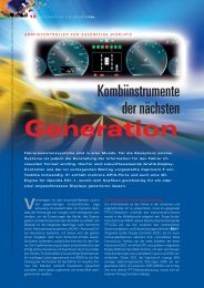
Figure 1 illustrates the AUTOSAR architecture and its layers<br />
as: Application layer, Run-time Environment (RTE), Service
SPECIAL EDITION FLEXRAYl AUTOMOTIVE<br />
2007l25<br />
© Carl Hanser Verlag, München www.hanser-<strong>automotive</strong>.de Nicht zur Verfügung im Intranet- und Internet-Angeboten sowie elektronischen Verteilern<br />
layer, ECU abstraction layer and MCU abstraction layer. The<br />
Application Layer comprises all functionality of the Application<br />
Software and consists of several Software Components<br />
(SW-C). The AUTOSAR Run-time Environment (RTE)<br />
is the Application Abstraction Layer, which acts as an interface<br />
between the application and the AUTOSAR Basic Software.<br />
The Basic Software is categorised into three groups;<br />
Service layer, ECU layer and Microcontroller Abstraction<br />
layer. The task of the service layer is to provide the basic<br />
function to the application and basic modules. Operating<br />
system, memory, and communication services belong to<br />
this category. The ECU abstraction layer interfaces <strong>with</strong> the<br />
drivers of the Microcontroller Abstraction Layer, while the<br />
Microcontroller Application Layer comprises the driver and<br />
software modules, which have direct access to the MCU’s<br />
internal resources. These two layers ensure<br />
that the application remains independent of<br />
ECU and MCU.<br />
The connection to the FlexRay bus system is<br />
the function of the FlexRay Communication<br />
Stack (yellow highlighted in figure 1). Parts of<br />
this communication service are located in a<br />
common module. These common parts are<br />
modules such as AUTOSAR COM, Diagnostic<br />
Com Manager (DCM), Generic NM, PDU (Protocol<br />
Data Unit) Router and IPDU Multiplexer.<br />
Each of these modules needs to be configured<br />
to the ECU demands. Looking at the pure Flex-<br />
Ray element, there is a FlexRay Transport Protocol<br />
Module, FlexRay Network management<br />
(NM) and XCP Transport protocol on FlexRay at<br />
the Communication service layer. The FlexRay<br />
NM takes care of the FlexRay-specific network<br />
management issues that are not available in the generic NM<br />
modules or where adaptation of generic NM signals becomes<br />
necessary. At the ECU Abstraction layer the FlexRayspecific<br />
element is the FlexRay interface module and external<br />
FlexRay device drivers (e.g. for FlexRay transceiver or<br />
external/internal FlexRay CC). This FlexRay Interface module<br />
routes the signals from the PDU Router to the dedicated<br />
driver, e.g. FlexRay driver or FlexRay transceiver driver. The<br />
FlexRay driver for an integrated FlexRay CC is part of the<br />
MCU abstraction layer. This driver module accesses the<br />
internal registers of the FlexRay CC, and again all these<br />
modules need configuration. All other HW modules such as<br />
CAN, memory driver, etc., also need to be configured,<br />
which leads to a large number of configuration settings.<br />
Nowadays the FIBEX format is used to keep track for the<br />
FlexRay Bus settings. The majority of them refer to the initialisation<br />
of the FlexRay driver. But tresos by Elektrobit provides<br />
configuration parameters for the other layers too. For<br />
example, the assignment of all signals throughout all layers<br />
can be defined <strong>with</strong> that tool, which has been fully adapted<br />
to the MB19460 series from Fujitsu. The software development<br />
can be performed in parallel to the basic software configuration<br />
because by definition, the application layer is<br />
independent from the basic software. When all basic software<br />
configurations are completed, a FlexRay signal flow<br />
throughout the modules should operate as follows:<br />
Figure 1: AUTOSAR architecture<br />
The example assumes that one SW-C wishes to transfer a<br />
signal to another SW-C. The transmitting SW-C does not<br />
know if its transfer is to a local module or to a module on<br />
another ECU. Therefore an initial request for a signal transmission<br />
is passed to RTE via the SW-C port. During configuration<br />
of RTE this SW-C port was assigned to AUTOSAR<br />
COM, so the RTE passes this signal to the AUTOSAR COM.<br />
Here the signal is submitted to the Protocol Data Unit Router<br />
(PDU) and new signal definitions are applied to meet low<br />
level hardware requirements. The PDU router passes the<br />
signal to the dedicated communication interface, according<br />
to the signal definition in the PDU Router. In this case the<br />
signal is mapped to the FlexRay communication driver, so<br />
the signal is passed to the FlexRay interface, which passes<br />
it again to the FlexRay driver according to the signal ID definition.<br />
The FlexRay driver itself will now write the signal data<br />
to the FlexRay CC message buffer and set Tx request. The<br />
signal data is transmitted via the FlexRay bus and received<br />
by the corresponding EC. At the receiver side, any SW-C<br />
can issue a signal read request to RTE. This request is passed<br />
through all modules – RTE, COM, PDU, and FlexRay<br />
interface – from where the signal data is retrieved. The Flex-<br />
Ray driver will read the message buffer and pass the value<br />
back to the upper layer.<br />
All these functions can be used on<br />
Fujitsu’s 32-bit MCU series<br />
MB91460. Together <strong>with</strong> a state-ofthe-art<br />
AUTOSAR configuration tool,<br />
tresos, the system designer has a<br />
powerful solution at its side. Today<br />
Fujitsu offers an off-the-shelf AUTO-<br />
SAR package for the MB91460<br />
series based on revision 2.0. Future<br />
upgrades to 2.1 and beyond are<br />
planned. Complemented by Fujitsu-<br />
’s starter kits, e.g MB91465X<br />
100PMC featuring a 100-pin Flex-<br />
Ray-MCU, anyone can discover all of<br />
the AUTOSAR-based FlexRay software<br />
capabilities of Fujitsu’s 32-bit<br />
platforms<br />
© <strong>automotive</strong><br />
Dipl. Ing. Matthias Steeg<br />
is application engineer at<br />
Fujitsu Microelectronics<br />
Europe, in the Automotive<br />
Business Unit. Since 2004<br />
he concentrates on Flex-<br />
Ray and became an expert<br />
for customer support in<br />
this application field."
26lA UTOMOTIVE 2007l SPECIAL EDITION FLEXRAY<br />
© Carl Hanser Verlag, München www.hanser-<strong>automotive</strong>.de Nicht zur Verfügung im Intranet- und Internet-Angeboten sowie elektronischen Verteilern<br />
Body and gateway microcontroller<br />
<strong>with</strong> embedded FlexRay<br />
FlexRay has become a standard interface for NEC Electronics. Since we joined<br />
the FlexRay consortium in 2003, we have launched two microcontrollers<br />
(V850E/CAG4-M, V850E/PHO3) <strong>with</strong> embedded FlexRay on the market<br />
and we have performed many application and simulation tests. From 2008<br />
onwards, our FlexRay MCUs will be found in OEM series FlexRay networks.<br />
The V850E/CAG4-M is a new member of NEC’s<br />
powerful 32-bit V850 RISC microcontroller family<br />
<strong>with</strong> embedded FlexRay communication<br />
controller based on the Bosch E-<br />
Ray IP Module R1.0. With 8 Kbytes<br />
of FlexRay message RAM, the<br />
V805E/CAG4-M is ready for applications<br />
<strong>with</strong> huge amounts of TX<br />
and RX data.<br />
Offering high performance, large memory<br />
and fully-fledged communication<br />
interfaces, it is optimized for<br />
<strong>automotive</strong> body applications like<br />
gateways, providing control of up to<br />
6 CAN as standard interfaces. Easy Fig. 1: V850E/<br />
access to the MOST world is provi-<br />
PHO3 package<br />
ded by the V850E/CAG4-M <strong>with</strong> its embedded MediaLB<br />
interface for very high data throughput, especially for<br />
asynchronous data transfer. The new multi-<br />
LIN master macro can connect up to<br />
6 LIN channels very efficiently<br />
and reduce the CPU load to a minimum.<br />
The V850E/CAG4-M also<br />
has a 16-bit parallel external bus<br />
interface for connecting to external<br />
components like flash or RAM.<br />
The timer structure is suitable for<br />
body applications offering multiple<br />
input capture and PWM output channels as<br />
well as a dedicated motor control. With realtime<br />
clock and power-saving mode support, the<br />
device is right for many car body applications.
SPECIAL EDITION FLEXRAYl AUTOMOTIVE<br />
2007l27<br />
© Carl Hanser Verlag, München www.hanser-<strong>automotive</strong>.de crescomedia.de Nicht zur Verfügung im Intranet- und Internet-Angeboten sowie elektronischen Verteilern<br />
The device’s internal window watchdog,<br />
parity on RAM, ECC on flash<br />
(single error correction, double error<br />
detection), CRC unit and FPU all support<br />
safety-relevant applications.<br />
Chassis MCU:<br />
V850E/PHO3<br />
The V850E/PHO3 is NEC Electronics’<br />
first MCU <strong>with</strong> embedded FlexRay. It<br />
is optimized for inverter control applications<br />
requiring control of up to two<br />
3-phase brushless DC motors simultaneously,<br />
for example in electronic<br />
power steering, braking or damping.<br />
Equipped <strong>with</strong> an embedded FlexRay<br />
communication interface and 2 CAN<br />
interfaces, the V850E/PHO3 is designed<br />
for advanced network architectures<br />
and future x-by-wire applications.<br />
Its on-chip safety features, such as CRC, ECC on<br />
flash and RAM, meet the highest safety requirements and<br />
support applications targeting IEC61508 SIL3 certification.<br />
Other V850 microcontrollers <strong>with</strong> embedded FlexRay are<br />
on our product roadmap and will be available soon to cover<br />
<strong>automotive</strong> applications like chassis, safety, body, gateway<br />
and audio.<br />
Fig. 2: AUTOSAR software architecture<br />
FlexRay solutions.<br />
© <strong>automotive</strong><br />
All our FlexRay microcontrollers offer fastest access to the<br />
FlexRay communication controller via a 32-bit non-multiplexed<br />
synchronous interface <strong>with</strong> minimal CPU interaction.<br />
Each MCU also includes a dedicated PLL that supplies the<br />
FlexRay controller <strong>with</strong> a separate clock and guarantees highest<br />
FlexRay timing accuracy.<br />
Nice to meet you:<br />
FlexRay Product Day<br />
November 29th, 2007<br />
Fellbach nearby Stuttgart<br />
Booth No. 24<br />
Control the FlexRay bus <strong>with</strong> reliable<br />
tools.<br />
Modular software and hardware design<br />
permit the user rapid access to FlexRay and<br />
other bus systems. FlexRay communication<br />
is easily built up <strong>with</strong> two integrated startup<br />
nodes and import of FIBEX data. The new<br />
high performance vehicle communication<br />
interface HSX <strong>with</strong> PowerPC-Core allows for<br />
high data throughput and time critical<br />
execution of FlexRay and other multi instance<br />
bus protocols. Its usage as diagnostic tester<br />
or for active and passive rest bus simulation<br />
or as gateway between CAN and FlexRay<br />
offers excellent flexibility to the developer.<br />
samtec is a supplier of cutting-edge software<br />
and hardware in the field of vehicle<br />
communication technology, <strong>with</strong> more than<br />
20 years of experience. We are<br />
glad to inform you personally<br />
under +49 711 45 80 90 or<br />
simply log onto www.samtec.de.<br />
Smart. Sensitive. Supporting.
28lA UTOMOTIVE 2007l SPECIAL EDITION FLEXRAY<br />
© Carl Hanser Verlag, München www.hanser-<strong>automotive</strong>.de Nicht zur Verfügung im Intranet- und Internet-Angeboten sowie elektronischen Verteilern<br />
FEATURES:<br />
V850E/CAG4-M<br />
V850E/PHO3<br />
· V850E @ 80 MHz <strong>with</strong> FPU @ 128 MHz <strong>with</strong> FPU<br />
· 512 Kbytes<br />
· 1 Mbytes flash/60<br />
flash/60 Kbytes RAM Kbytes RAM<br />
· FlexRay (2-channel,<br />
· FlexRay (2-channel,<br />
v2.1, 8 Kbytes RAM)<br />
v2.1, 6 Kbytes RAM)<br />
· 2 x CAN<br />
· 3-wire MediaLB interface<br />
(32 + 32 message buffer)<br />
· 6 x CAN (6 x 48 message<br />
· 2 x CSI, 2 x buffered CSI,<br />
buffer; mirror mode)<br />
3 x LIN UART<br />
· 4 x CSI, 6 x LIN-UART · 2 x ADC (10+10-channel),<br />
(+MLM), I2C<br />
10-bit, 2 µs<br />
· ADC: 10-channel, 10-bit, 2 µs · 2 x real-time pulse unit<br />
·144 QFP package<br />
for motor control<br />
· 357 PBGA package<br />
Fig. 3: V850E/PHO3<br />
FlexRay conformance test<br />
Because FlexRay is a complex protocol, it’s essential that<br />
each controller behaves as described in the FlexRay specification.<br />
This prompted the FlexRay consortium to specify<br />
a conformance test that was then implemented by TUEV<br />
Nord. Based on 275 test cases, the test checks the correct<br />
functional behaviour of the embedded FlexRay communication<br />
controller as described in the current FlexRay v2.1<br />
specification. The FlexRay conformance test is a prerequisite<br />
for interoperability and faultless communication between<br />
FlexRay communication controllers.<br />
As the world’s first microcontroller <strong>with</strong> embedded FlexRay,<br />
the V850E/PHO3 passed the FlexRay CT at TUEV NORD b/o<br />
2007. This is documented by a conformance test certificate<br />
that is obligatory for every microcontroller implemented in<br />
a FlexRay cluster for use in series production cars.<br />
In addition to the conformance test, NEC Electronics has<br />
conducted an extensive in-house evaluation of the FlexRay<br />
communication controller, using both simulation runs and<br />
actual applications.<br />
NEC Electronics is also an active member of the JasPar<br />
consortium that conducts several stress and interoperability<br />
tests capable of proving<br />
that our V850<br />
MCU also runs correctly<br />
in an inhomogeneous<br />
FlexRay network.<br />
FlexRay evaluation<br />
board and AUTOSAR<br />
starter kit<br />
NEC Electronics joined the AUTOSAR partnership<br />
as a premium member in March 2004. The main<br />
focus <strong>with</strong>in the AUTOSAR partnership is on software modules<br />
that are either very close to, or interact directly, <strong>with</strong><br />
MCU hardware. NEC Electronics’ microcontroller abstraction<br />
layer (MCAL) software contains all AUTOSAR device<br />
driver and interface modules. To match the exceptional quality<br />
standards of the hardware, the MCAL software was developed<br />
using best-in-class software processes certified to<br />
CMMI Level 5 and SPICE Level 3. Several software companies,<br />
like Vector Informatics and Elektrobit, already offer<br />
a complete AUTOSAR stack (from operating system<br />
through memory management to communication) for the<br />
V850E/PHO3 based on our MCAL.<br />
To facilitate the introduction of AUTOSAR on the market,<br />
NEC Electronics developed an AUTOSAR starter kit that includes<br />
both hardware and software. The hardware is an evaluation<br />
board <strong>with</strong> a V850E/PHO3 MCU and several interfaces.<br />
The software contains the complete AUTOSAR<br />
MCAL including the FlexRay driver/interface software and<br />
a configuration tool.<br />
The AUTOSAR starter kit is ideal for software engineers<br />
who would like to start working <strong>with</strong> AUTOSAR, and is the<br />
perfect way to create first FlexRay applications. It includes:<br />
Hardware:<br />
■ PCB <strong>with</strong> V850E/PHO3<br />
■ Interfaces for FlexRay, CAN, CSI, UART<br />
■ Interface for an external FPGA<br />
■ Motor control interface<br />
■ Display and LEDs for signaling test results<br />
Software:<br />
■ AUTOSAR MCAL software<br />
■ AUTOSAR configuration tool<br />
■ Demo application<br />
■ Documentatio<br />
starter kit board<br />
Dipl-Ing Holger Schmerling studied<br />
electrical engineering at the Cologne<br />
University of Applied Sciences specializing<br />
in communication systems. For<br />
the past 5 years he has worked as an<br />
application engineer on FlexRay,<br />
TTCAN and AUTOSAR in the NEC Electronics<br />
Automotive Business Unit in<br />
Düsseldorf.
SPECIAL EDITION FLEXRAYl AUTOMOTIVE<br />
2007l29<br />
© Carl Hanser Verlag, München www.hanser-<strong>automotive</strong>.de Nicht zur Verfügung im Intranet- und Internet-Angeboten sowie elektronischen Verteilern<br />
FlexRay Controller -<br />
Integrated or Discrete?<br />
What are the advantages for<br />
<strong>automotive</strong> system designers<br />
of using a discrete FlexRay<br />
communications controller and<br />
one integrated into its high end<br />
32-bit microcontroller family<br />
Automotive system designers require a<br />
combination of performance, flexibility,<br />
cost effectiveness, scalability and safety<br />
that is sometimes hard to reach. A fully integrated<br />
solution can be cost effective but requires<br />
a whole new system design.<br />
While designs have more pressure on space,<br />
using a discrete solution can take more space but<br />
provides the potential to upgrade the system easily.<br />
This also allows developer to use a range of different<br />
processors, both <strong>with</strong>in a family of devices,<br />
re-using the same software, but also across different<br />
families for different applications, from cars to<br />
high end motor cycles.<br />
A key example of this comes from using the Flex-<br />
Ray communications protocol. Version 2.1 of the<br />
specification has been available for several years<br />
now, but the devices that support the new standard<br />
have taken time to come to the market. One<br />
of the first was the CIC310 stand alone FlexRay<br />
communication controller, which has been qualified<br />
in many designs, but now this same design<br />
has been integrated into the TC1797 TriCore 32-bit<br />
controller (Figure 1). This allows system integrators<br />
to build fully FlexRay v2.1 compliant in-vehicle<br />
networks for powertrain, chassis and body applications.<br />
The FlexRay controller core is based on the widely<br />
used E-RAY design from system supplier Bosch<br />
and is integrated into the TC1797, part of the AUDO<br />
FUTURE microcontroller family. This family uses<br />
the high performance 32-bit TriCore processor core that<br />
combines microcontroller functions <strong>with</strong> digital signal processing<br />
and the industry’s highest density flash memory.<br />
The family includes a wide range of peripherals such as a<br />
fast ADC, DMA memory engine and several serial interfaces<br />
and external bus Interfaces. Most of the family also has<br />
an additional 32-bit Peripheral Control Processor (PCP) on<br />
board that offloads the main CPU by running the low-level<br />
drivers for the integrated peripherals.<br />
The previous TC1796 recently achieved a score of 100 Automark<br />
in the certified EEMBC Benchmark (http://<br />
www.eembc.org/) – the highest score for an <strong>automotive</strong><br />
qualified microcontroller in this frequency range. The<br />
TC1797 adds another 30% system performance <strong>with</strong> its Tri-<br />
Core operating at 180 MHz.<br />
This level of performance and integration is aimed at high<br />
end engine control units (ECUs) to handle the complex<br />
algorithms for emission control and FlexRay is mandatory<br />
in current and future designs of these systems (Figure 2).<br />
Discrete: The flexible way<br />
At the same time there can be advantages from using a<br />
discrete controller. The CIC310 is a standalone FlexRay<br />
V2.1 Protocol Controller based on the same Bosch IP and
30lA UTOMOTIVE 2007l SPECIAL EDITION FLEXRAY<br />
© Carl Hanser Verlag, München www.hanser-<strong>automotive</strong>.de Nicht zur Verfügung im Intranet- und Internet-Angeboten sowie elektronischen Verteilern<br />
Figure 1:The TC1797 uses a new high performance 32-<br />
bit TriCore CPU that combines microcontroller functions<br />
<strong>with</strong> digital signal processing and the industry’s highest<br />
density flash memory.<br />
© <strong>automotive</strong><br />
has already passed the mandatory FlexRay Conformance<br />
Test. It is partnered <strong>with</strong> a microcontroller or microprocessor<br />
via a standard interface and allows designers to provide<br />
FlexRay as an optional feature that can be easily integrated<br />
into an existing hardware and software design. In<br />
this case, the footprint for the CIC310 and the according<br />
FlexRay transceiver will be available on printed circuit board<br />
but the devices will be only mounted if needed, and this<br />
also provides an upgrade path for existing systems.<br />
Figure 2:The TC1797 microcontroller is optimized for engine management<br />
systems and transmission. In engine management, the TriCore provides lower fuel<br />
consumption and improved emissions.With a number off build-in safety features<br />
like a Memory Protection Unit (MPU) the TriCore is also a fit for safety critical<br />
application in chassis control area like high-end sensor clusters and suspension.<br />
The controller supports both FlexRay communication channels<br />
<strong>with</strong> a maximum bandwidth of 10 Mbit/s each and provides<br />
8.25 KBytes of configurable message RAM for storing<br />
up to 128 messages. The redundancy of the two independent<br />
communication channels, along <strong>with</strong> the FlexRay<br />
time-triggered communication schemes and high bandwidth<br />
are key for safety critical <strong>automotive</strong> applications.<br />
Low power is also a key feature of the CIC310. Manufactured<br />
in a 130 nm process technology, the core consumes<br />
30 mA to 50 mA.<br />
To support designers, a number of hardware features are<br />
implemented. Eight independent DMA channels offer an<br />
efficient transfer mode <strong>with</strong>out using the host CPU. Several<br />
interrupt lines give full control of the CIC Channel Host<br />
Interface (CHI) and the E-RAY communication controller,<br />
and this provides three different interfaces (Figure 3):<br />
A low pin count SPI (Serial Peripheral Interface) interface<br />
supporting up to 20 MBaud Bandwidth<br />
A configurable 8/16-bit wide bus parallel interface including<br />
a 13 Bit address bus (<strong>with</strong> address extension mechanism<br />
to 32-bit) supporting up to 10 MByte/sec bandwidth<br />
A high speed serial MLI (Micro Link Interface) supporting<br />
up to 40 MBaud<br />
This flexible channel host interface means the CIC310 can<br />
be used <strong>with</strong> almost any microcontroller or microprocessor<br />
architecture available in the market.<br />
The new TC1767 and TC1736 TriCore controllers do not have<br />
integrated FlexRay and provide a path for more cost optimised<br />
designs from the TC1797 using the same software. Both<br />
integrate the same microcontroller core as TC1797, the same<br />
built-in safety features like a Memory Protection<br />
Unit (MPU) and a software-compatible<br />
peripheral set. In addition to powertrain applications,<br />
the TC1767 and TC1736 can also be<br />
used in safety critical application in chassis<br />
control area like high-end sensor clusters and<br />
suspension.<br />
To connect the TriCore to the CIC310, all three<br />
interface options available can be used. The<br />
most efficient interface is using the Micro<br />
Link Interface (MLI) as this provides synchronous<br />
high-speed serial connection for automatic<br />
data transfer/request transaction between<br />
a local and a remote controller. It also<br />
supports transparent read/write access <strong>with</strong><br />
a low pin count.<br />
For the connection between the processor<br />
and the Companion IC only eight pins are<br />
necessary - four each for transmit and receive.<br />
Further pins are available for additional<br />
interrupt lines to monitor both the ERAY Controller<br />
and the CIC310.<br />
As the TriCore internal bus structure supports<br />
the DMA capability of the CIC310 via MLI<br />
interface, the FlexRay communication is supported<br />
<strong>with</strong> minimum performance requirement<br />
from the main TriCore CPU. Other internal<br />
DMA operations can also be offloaded to<br />
the on-chip 32-bit peripheral controller.<br />
© <strong>automotive</strong>
SPECIAL EDITION FLEXRAYl AUTOMOTIVE<br />
2007l31<br />
© Carl Hanser Verlag, München www.hanser-<strong>automotive</strong>.de Nicht zur Verfügung im Intranet- und Internet-Angeboten sowie elektronischen Verteilern<br />
Figure 3: Infineon’s Channel Host Interface (CHI) Concept for the<br />
CIC310 supports 3 different options: a standard parallel interface,<br />
a Serial Peripheral Interface (SPI) and a High Speed Serial Micro<br />
Link Interface (MLI)<br />
© <strong>automotive</strong><br />
Well supported<br />
The discrete controller is not just applicable to the TriCore<br />
family. The latest XC2200, XC2300 and XC2700 families of<br />
controllers are based on the Infineon’s C166S V2 microcontroller<br />
architecture and can all make use of the discrete<br />
FlexRay controller.<br />
The XC2200 is designed for body applications like Body<br />
Central Module, Central Gateway and air-conditioning <strong>with</strong><br />
power consumption in standby down to 50 uA as well as<br />
extended communication capabilities. The XC2300 family<br />
covers applications in the safety critical area like airbag and<br />
Electronic Power Steering (EPS) by adding Error Correction<br />
Code (ECC) on all memories, memory protection, a CRC<br />
(Cyclic Redundancy Check) and redundant analog-digital<br />
converters, and supports systems to be certified in<br />
IEC61508 level SIL3. The XC2700 32-bit microcontrollers<br />
are optimised for Engine Management and allow system<br />
makers to build cost-effective electronic engine control in<br />
motorcycles around the world to meet upcoming emission<br />
standards.<br />
Interfacing the XC2200, XC2300 and XC2700 to the CIC310<br />
can be either through the standard 8- /16-bit parallel bus<br />
interface or through one of the incorporated USIC’s (Universal<br />
Serial Interfaces). These support the fast SPI standard,<br />
running a bandwidth of up to 20 Mbit per second between<br />
the CIC310 and the microcontroller. In applications<br />
<strong>with</strong> critical latency requirements, the parallel interface is<br />
the recommended solution as it supports a speed of up to<br />
10 MByte per second <strong>with</strong> very low latency impact.<br />
But implementation is also an important issue for designers,<br />
so AUTOSAR software drivers for the CIC310 are<br />
available and have already been proven by the AUTOSAR<br />
Validator project. At the same time, the TriCore family as<br />
well as the XC2200, XC2300 and XC2700 families are supported<br />
by a full suite of development tools including evaluation<br />
boards, debuggers, compilers and documentation.<br />
Automotive equipment makers are already using FlexRay<br />
Kai Konrad (l.) is Product Marketing Manager<br />
for Microcontrollers Automotive at Infineon<br />
Technologies, and Holger Huber (r.) is Product<br />
Marketing Manager for Microcontrollers<br />
Automotive at Infineon Technologies<br />
in series production, and broad introduction is planned<br />
already in 2009. This means a wide range of<br />
different solutions will be required by the equipment<br />
makers, all based around FlexRay as the<br />
communications controller.<br />
Having both integrated, tightly coupled implementations<br />
such as the TC1797 and the discrete<br />
CIC310 allows the system design to select the right processor<br />
core for the application and still easily provide Flex-<br />
Ray communications. The discrete approach also provides<br />
a simple upgrade path for today’s designs to become Flex-<br />
Ray-enabled.<br />
FlexPower<br />
for your solutions<br />
FlexConfig Developer<br />
Import and Export of FIBEX 1.2 and FIBEX 2.0<br />
State-of-the-art graphical editors and user assistance<br />
<br />
<br />
<br />
1-year free support and updates<br />
Robert-Bosch-Str. 6<br />
Fon: +49 7161 5023-0<br />
www.tzm.de<br />
intuitive and<br />
<br />
TZ Mikroelektronik<br />
<br />
tool for FlexRay <strong>with</strong><br />
FIBEX-support.<br />
New<br />
<br />
<br />
D-73037 Göppingen<br />
Fax: +49 7161 5023-444<br />
sales@tzm.de<br />
A company of Steinbeis GmbH & Co. KG für Technologietransfer
32lA UTOMOTIVE 2007l SPECIAL EDITION FLEXRAY<br />
© Carl Hanser Verlag, München www.hanser-<strong>automotive</strong>.de Nicht zur Verfügung im Intranet- und Internet-Angeboten sowie elektronischen Verteilern<br />
C&S: Tested<br />
Products online<br />
To support engineers developing<br />
new network components, the C&S<br />
group provides a list of tested products<br />
on the internet. The list is still<br />
not complete, but C&S is working on<br />
it! The listed CAN and LIN devices<br />
have been tested at C&S - like many<br />
others, which they are not allowed<br />
to publish.. FlexRay is in the pipeline.<br />
■ http://www.cs-group.de<br />
Kyocera:<br />
Crystal Unit for<br />
Engine Control<br />
Circuits<br />
For <strong>automotive</strong> applications Kyocera<br />
introduces the surface mount type<br />
crystal unit CX3225SA. With an operating<br />
temperature range of ?40 to<br />
+150 °C, a good rust prevention performance<br />
and the small and low profile<br />
(3.2?2.5?0.8 mm) it is dedicated<br />
to engine control applications. The<br />
usage of a ceramic package is resulting<br />
in high reliability. The frequency<br />
range is from 12 MHz to 54 MHz<br />
<strong>with</strong> a frequency tolerance of ±50<br />
x10-6 at 25 °C. The devices are<br />
reflow compatible <strong>with</strong> improved<br />
solderability.<br />
■ http://global.kyocera.com/<br />
application/<strong>automotive</strong>/product/<br />
compo/crystal.html<br />
PRODUCTS<br />
Ixxat: FlexRay/<br />
CAN platform<br />
The FlexRay CCM from Ixxat Automation<br />
is a FlexRay/CAN platform<br />
for both PC-based and stand-alone<br />
applications. As an open PC interface,<br />
it is measuring hardware for<br />
comprehensive analysis and simulation<br />
tasks for FlexRay and CAN<br />
networks. An exact local time enables<br />
synchronous logging of Flex-<br />
Ray and CAN messages. The Flex-<br />
Ray analysis is carried<br />
out both via<br />
the FlexRay protocol<br />
module and via<br />
an asynchronous bit<br />
stream analysis, so<br />
that both the start-up<br />
behavior and specific<br />
errors on the FlexRay<br />
bus can be detected.<br />
The micro-controller<br />
system (MPC 866,<br />
130 MHz) allows realtime-critical<br />
tasks to<br />
be performed directly on the hardware<br />
in the form of add-on software<br />
modules. In this way, realtime<br />
rest bus simulations, protocol<br />
implementations or emulation<br />
functions can be implemented. The<br />
interface is connected to FlexRay<br />
via the current version of the Flex-<br />
Ray chip (freescale MFR 4300).<br />
Upgrading to new chip generations<br />
is carried out <strong>with</strong> plug-in modules.<br />
With the new dual chip extension,<br />
two FlexRay cold starters can be<br />
implemented <strong>with</strong> one hardware<br />
platform. Thus the device can also<br />
start FlexRay networks containing<br />
only integration nodes. The Flex-<br />
Ray CCM can be used as an autonomous<br />
device, which enables use<br />
as a FlexRay/CAN gateway, for<br />
example. The interface communicates<br />
via Fast Ethernet TCP/IP<br />
(10/100Mbit/s) and is designed for<br />
processing of 100 % bus load on all<br />
bus systems.<br />
In addition to two 10 Mbit/s Flex-<br />
Ray interfaces, the interface has<br />
two CAN interfaces (ISO/IS 11898-<br />
2 high-speed CAN und ISO/IS<br />
11898-3 low-speed CAN).<br />
To control external hardware components,<br />
the interface has four trigger<br />
outputs, which can be controlled<br />
via FlexRay messages or by the<br />
FlexRay cycle. In addition, two trigger<br />
inputs are available.<br />
■ http://www.ixxat.com
SPECIAL EDITION FLEXRAY · PRODUCTSl AUTOMOTIVE<br />
2007l33<br />
© Carl Hanser Verlag, München www.hanser-<strong>automotive</strong>.de Nicht zur Verfügung im Intranet- und Internet-Angeboten sowie elektronischen Verteilern<br />
Agilent:<br />
Vehicle Protocol Tester<br />
For vehicle topologies consisting of CAN and LIN networks,<br />
Agilent’s Vehicle Protocol Tester VPT501 is a<br />
debugging and analysis tool for complex communication<br />
relations. The VPT501 has a robust housing that is designed<br />
for the usage in vehicles, <strong>with</strong> CAN (2x) and LIN<br />
(2x) and the digital input/output interfaces. The following<br />
key features are packed into the box:<br />
• various and extensive data analysis of network communication<br />
• innovative and automated timing analysis capabilities<br />
• simple configurable rest-bus emulation <strong>with</strong>out programming<br />
expenditure<br />
• an integrated data logger for stand-alone mode<br />
The timing analysis capabilities make it possible to identify<br />
and analyze communication problems in the network<br />
faster, simpler and more effectively. During the recording<br />
of the communication, the timing checker determines<br />
the minimum, maximum and average follow-up time for<br />
all frames in connected CAN and LIN networks automated<br />
and in real time.<br />
We work hand<br />
in glove <strong>with</strong> you<br />
Infotainment<br />
The VPT501 supervises time borders that can be configured<br />
by the user and indicates each violation online.<br />
This enables fastest identification of the source of error<br />
and analysis of the time performance in case of an error.<br />
The signal chain analysis allows a simple, automated<br />
timing analysis of data flow beyond interfaces and networks.<br />
Thereby for example gateway latencies, response<br />
time, physical -to-protocol conversion, protocol-tophysical<br />
conversion or synchronized event timing can be<br />
determined in a very simple way.<br />
■ http://www.home.agilent.com<br />
Testing<br />
Technical innovation guarantees successful business<br />
We keep you on the move. As a comprehensive provider of customized IT<br />
services, we are a reliable and competent partner for the entire <strong>automotive</strong><br />
and transport industry. Based on profound industry knowledge and a strong<br />
sense for trends, we develop innovative solutions for today and tomorrow.<br />
Get more information: www.tietoenator.de<br />
Safety<br />
AUTOSAR
© Carl Hanser Verlag, München www.hanser-<strong>automotive</strong>.de Nicht zur Verfügung im Intranet- und Internet-Angeboten sowie elektronischen Verteilern<br />
34lA UTOMOTIVE 2007<br />
Elmos will deliver<br />
FlexRay chips to BMW<br />
Elmos Semiconductor AG<br />
announced to be a supplier of<br />
integrated circuits of the new<br />
high-speed bus standard Flex-<br />
Ray at BMW. Delivery is expected<br />
to start mid-2008 and will<br />
include a star coupler for Flex-<br />
Ray systems to begin <strong>with</strong>. The<br />
newly developed integrated circuit<br />
replaces four conventional<br />
single transceivers.<br />
The FlexRay IC E910.56 is a<br />
fourfold star coupler, which can<br />
be roused via network and has<br />
its own SPI diagnoses interface<br />
at its disposal. Thus the IC enables<br />
a comprehensive functionality<br />
for diagnoses coupled<br />
<strong>with</strong> appropriate error detection<br />
and treatment. The E910.56<br />
allows for a low-priced and<br />
space-saving intelligent FlexRay<br />
network management. Due to<br />
optimized EMC behaviour the<br />
star coupler handles high data<br />
streams of up to 10 Mbit/s and<br />
offers real-time networking.<br />
■ http://www.elmos.de<br />
Samtec: Vehicle<br />
Communication Interface<br />
Samtec’s HSX is a modular built VCI (Vehicle Communication<br />
Interface) <strong>with</strong> a 32 Bit PowerPC-Core (350 MHz). Due<br />
to its multibus design diagnostic tasks can be simultaneously<br />
executed on several bus systems like LIN, SAE J1850<br />
and SAE J1708. Up to 6 Full CAN interfaces and 4 K-Line<br />
interfaces (<strong>with</strong> up to 500 kBaud in K-Line/RS485 mode)<br />
are available. Very high data throughput and precise time<br />
synchronization enable the analysis of control unit<br />
networks <strong>with</strong> high speed buses like FlexRay. The<br />
FlexRay interface is capable of 2x 10 MBit/s.<br />
Further implementation areas include rest<br />
bus simulation, remote vehicle diagnostics<br />
via wLAN or usage as gateway. Furthermore<br />
the HSX interface can be integrated<br />
in tool chains that are based on the new<br />
MVCI standards as per the ISO 22900 norms.<br />
Hence the interface can be used not only <strong>with</strong><br />
samtec software but also <strong>with</strong> other diagnostic applications<br />
that conform to the norms.<br />
PRODUCTS<br />
Xilinx<br />
LogiCORE<br />
Xilinx LogiCORE FlexRay controller<br />
implements the FlexRay communication<br />
protocol as defined in the FlexRay<br />
Protocol Specification v2.1 Rev A. The<br />
FlexRay controller implementation<br />
supports a single communication<br />
channel <strong>with</strong> configurable Buffer storage<br />
supporting up to 128 messages.<br />
The Payload that can be supported by<br />
the controller during synchronous or<br />
aysnchronous transmission is userconfigurable.<br />
The number of transmit<br />
buffers in the FlexRay controller can<br />
be configured as well as the Receive<br />
buffers from a minimum of two to a<br />
maximum of 128 in powers of two.<br />
The block RAM resource utilization<br />
varies, based on the number of Transmit<br />
and Receive buffers and the configurable<br />
payload length. The depth of<br />
the Receive FIFO in the FlexRay controller<br />
can be user-configured from a<br />
minimum of two to a maximum of 128<br />
in powers of two. The core can be<br />
used in standalone mode or connected<br />
to Xilinx MicroBlaze or PowerPC<br />
processors.<br />
■ http://www.xilinx.com<br />
It is compatible <strong>with</strong> the diagnostic suite samDia, the sam-<br />
DiaX control element (ActiveX) and the samMCD3 Server<br />
(Standardized Runtime System for Vehicle Diagnosis).<br />
■ http://www.samtec.de
SPECIAL EDITION SPECIAL FLEXRAY EDITION · PRODUCTSl FLEXRAYl AUTOMOTIVE<br />
2007l35<br />
© Carl Hanser Verlag, München www.hanser-<strong>automotive</strong>.de Nicht zur Verfügung im Intranet- und Internet-Angeboten sowie elektronischen Verteilern<br />
Esterel Technologies:<br />
Scade 6.0 now available<br />
From Esterel Technologies Scade 6.0 is now available. SCADE 6.0<br />
provides a unified modeling, verification and certified code generation<br />
capability called the ‘Unified Modeling Style’ that enables<br />
embedded systems and software developers to freely combine<br />
and nest arrayed data flow elements and state machines in a single,<br />
fully integrated environment. Developers of demanding safety-critical<br />
mixed data flow and state machines applications will<br />
benefit from this unprecedented modeling freedom enabled by<br />
SCADE 6.0 in terms of design and verification time decrease,<br />
enhanced generated code size and<br />
speed as well as greater design<br />
flexibility and reusability. Existing<br />
modeling solutions rely on the collaboration<br />
between two independent<br />
modeling editors; however,<br />
SCADE 6.0 simplifies the work of<br />
the application developer. Now,<br />
the developer can focus on the<br />
productivity of the modeling activity,<br />
in the knowledge that all the<br />
certification and verification optimization<br />
benefits of the previous<br />
SCADE releases are maintained.<br />
The process-centric SCADE 6.0<br />
“Certified Software Factory“ features<br />
eight fully integrated modules<br />
that support the process of creating<br />
safety-critical application<br />
software:<br />
• the design of the software<br />
models <strong>with</strong>in the Unified Modeling<br />
Style, their integration <strong>with</strong><br />
configuration management tools<br />
and the automatic generation of<br />
documentation, <strong>with</strong> SCADE 6.0<br />
Advanced Modeler<br />
• the traceability of the software<br />
models versus system requirements,<br />
<strong>with</strong> SCADE 6.0 Requirements<br />
Management Gateway<br />
(integrating TNI Software’s Reqtify<br />
technology)<br />
• the validation of the models<br />
through model test coverage<br />
(SCADE 6.0 Model Test Coverage)<br />
and formal verification of safety<br />
properties (SCADE 6.0 Design Verifier,<br />
powered by Prover Technologies<br />
A.B. Prover Plug-in for<br />
SCADE)<br />
• the automatic and certified code<br />
generation, <strong>with</strong> SCADE 6.0 KCG<br />
Qualified Code Generator, and its<br />
integration of the target platform<br />
• the verification of the correct compilation of the generated<br />
code and execution on the target platform <strong>with</strong> SCADE<br />
6.0 Compiler Verification Kit<br />
Several import/export capabilities are also enabled by<br />
SCADE 6.0, such as the import of system and software<br />
architecture, <strong>with</strong> SCADE 6.0 SysML/UML Gateway for<br />
Rhapsody and the import of algorithm designs.<br />
■ www.esterel-technologies.co
© Carl Hanser Verlag, München www.hanser-<strong>automotive</strong>.de Nicht zur Verfügung im Intranet- und Internet-Angeboten sowie elektronischen Verteilern<br />
36lA UTOMOTIVE 2007<br />
austriamicrosystems:<br />
High performance <strong>automotive</strong> ICs<br />
PRODUCTS<br />
LeCroy: Expanding Automotive Tests<br />
<strong>with</strong> Integrated FlexRay Trigger and Decode Capabilities<br />
With the AS8221, austriamicrosystems has developed<br />
a standard product for automobile data bus applications.<br />
The FlexRay transceiver IP is also licenced to Infineon,<br />
one of the world’s largest manufacturer of semiconductors<br />
for <strong>automotive</strong> applications.<br />
But the company offers a lot more for <strong>automotive</strong> application,<br />
e.g. micro-power A/D converter and a analog/mixed-signal<br />
foundry offering RF CMOS, High-Voltage<br />
CMOS, BiCMOS and SiGe-BiCMOS processes.<br />
austriamicrosystems’ business unit Full Service Foundry<br />
recently announced a further improvement of its<br />
design environment “HIT-Kit” for its advanced 0.35µm<br />
High-Voltage CMOS process H35. It is ideally suited for<br />
high voltage product design like power management<br />
products, display drivers, sensors and sensor interfaces<br />
and any kind of <strong>automotive</strong> applications just to<br />
name a few. The HIT-Kit 3.72 based on Cadence version<br />
5.1.41 includes updated periphery cell libraries up<br />
to 50V as well as the recently announced set of 20V<br />
LeCroy announces a FlexRay solution that provides complete<br />
trigger and decode capabilities for the WaveRunner<br />
Xi series of oscilloscopes. LeCroy’s solution correlates physical<br />
layer signals <strong>with</strong> protocol layer data in one display,<br />
and the FlexRay trigger<br />
hardware is completely<br />
integrated inside the oscilloscope.<br />
The internal FlexRay trigger<br />
can isolate static and<br />
dynamic slot IDs, cycle<br />
count number, frame qualifiers<br />
and symbols while<br />
the decoder shows a color<br />
coded overlay directly on<br />
top of the physical layer<br />
waveform. Since the trigger<br />
is not a node on the<br />
FlexRay network, no network<br />
re-programming is<br />
required, simply connect a differential probe to the bus and<br />
capture data. The user interface is easy to navigate, and the<br />
touch screen display provides easy access to all protocol<br />
triggers. Supported FlexRay protocol triggers include static<br />
and dynamic IDs, Frame Cycle Count, Frame Qualifiers<br />
(NFI, SyFI, StFI) and TSS Symbol. As <strong>with</strong> other serial data<br />
solutions, LeCroy features conditional triggering to set a<br />
trigger condition of in range, out of range, less than or greater<br />
than. This is ideal for triggering on a range of slot IDs<br />
or cycle numbers.<br />
LeCroy deconstruct physical layer serial data signals and<br />
display decoded data <strong>with</strong> visually intuitive color coded<br />
overlays. These overlays<br />
clearly identify different<br />
parts of the data being captured<br />
and allow the user to<br />
quickly identify the data of<br />
interest; speeding up the<br />
debugging process also for<br />
I2C, SPI, UART, RS-232,<br />
LIN. The solution offers the<br />
ability to decode 4 signals<br />
simultaneously. These 4<br />
signals can all be FlexRay<br />
or any combination of the<br />
protocols supported. Along<br />
<strong>with</strong> displaying decoded<br />
data overlaid on the waveform,<br />
an interactive table is provided. Entries in this table<br />
can be selected and automatically zoomed to preventing<br />
the need to scroll through long records. To further simplify<br />
how data is located a search function is built in to the zoom<br />
trace to quickly locate a specific slot ID or cycle number.<br />
This advanced set of tools works on live data as well as<br />
math functions and waveforms stored in memory<br />
■ http://www.lecroy.com<br />
devices optimized for power management products<br />
and display drivers in battery powered applications. In<br />
addition the HIT-Kit offers unique design utilities like<br />
Safe Operating Area Check (SOAC) tool, automatic layout<br />
generators for high-voltage device and guard-ring<br />
generation and special layout verification utilities like<br />
leakage check.<br />
The new Cadence HIT-Kit v3.72 contains a complete<br />
set of fully silicon-qualified standard cells, periphery<br />
cells and general purpose analog cells such as comparators,<br />
operational amplifiers, low power A/D and D/A<br />
converters. Custom analog devices, physical verification<br />
rule sets for Assura DRC/LVS/EXT, as well as excellent<br />
characterized circuit simulation models enable<br />
rapid design starts of complex high performance<br />
mixed-signal ICs.<br />
■ http://asic.austriamicrosystems.com/<br />
hitkit/index.html
© Carl Hanser Verlag, München www.hanser-<strong>automotive</strong>.de Nicht zur Verfügung im Intranet- und Internet-Angeboten sowie elektronischen Verteilern<br />
FLEXRAY · PRODUCTSl AUTOMOTIVE<br />
ESG: Space for<br />
Innovation and Growth<br />
With the removal of around 650 employees<br />
to Fürstenfeldbruck, ESG Elektroniksystem-<br />
und Logistik-GmbH has put its<br />
new company headquarters into operation.<br />
The new building replaces the previous<br />
headquarters, the ESG tower in<br />
Munich. At its new location, the company<br />
receives a modern building that has been<br />
tailored to the requirements of a high tech<br />
company.<br />
Recently the company has developed a<br />
simulation and demonstration platform for<br />
car driver assistance systems. The system<br />
<strong>with</strong> the name MoPAC, „Modular Platform<br />
for Automotive Applications“, enables ESG<br />
to simulate and assess any present and<br />
future assistance functions in a compact<br />
construction. Because of the system’s<br />
diversity of interfaces and ist open architecture,<br />
a multitude of connection possibilities<br />
for enhanced sensor systems and<br />
actuating elements is available.<br />
This system uses a central nodal point,<br />
based on an MPC5554 (microcontroller),<br />
to link various sub-functions to one another<br />
and to realise the overall function. A<br />
PC <strong>with</strong> a webcam<br />
is connected over an Ethernet interface.<br />
Furthermore, the platform communicates<br />
<strong>with</strong> other sensor systems and actuating<br />
elements via FlexRay, LIN, CAN and Zig-<br />
Bee (wireless). A specially adapted conveyor<br />
belt is used to simulate the driving<br />
surface. Enhanced control features are<br />
implemented on the central PowerPC<br />
2007l37<br />
platform and are strictly separated from<br />
the communication drivers both spatially<br />
and temporally by a virtualisation concept,<br />
so that high safety requirements can be<br />
adhered to.<br />
The system is also used to realise camerabased<br />
assistance systems, such as automatic<br />
distance control and avoidance<br />
manoeuvres. In doing so, efficient object<br />
recognition algorithms are used to locate<br />
vehicles in the setting. The PC takes on<br />
image processing and object recognition<br />
and supplies the positions of the located<br />
objects to the PowerPC via Ethernet. This<br />
information forms the basis for the integrated<br />
control algorithm, which is used to<br />
position a vehicle stably on the conveyor<br />
belt and to trigger responses to recognised<br />
foreign objects. The stabilised behaviour<br />
of the vehicle on the conveyor belt<br />
forms the basis on which the system<br />
intervenes into the driving process.<br />
The concept’s modularity means that it is<br />
possible to straightforwardly connect<br />
various bus systems, integrate enhanced<br />
sensor systems and control several vehicles.<br />
The concept also facilitates the realisation<br />
of assistance functions for which<br />
communicating vehicles are a prerequisite.<br />
ESG is providing an insight into the<br />
possibilities of car assistance systems<br />
and for this reason possesses a suitable<br />
integration and simulation environment<br />
for such systems.<br />
■ http://www.esg.eu<br />
FlexRay<br />
Analysis & Residual<br />
Bus Simulation<br />
FlexRay CCM<br />
Universal PC interface<br />
for FlexRay and CAN<br />
Open application<br />
interface<br />
Real-time residual bus<br />
simulation<br />
Multibus Analyser<br />
Transmission, reception<br />
and interpretation<br />
of FlexRay and CAN<br />
messages<br />
Open programming<br />
interface and scripting<br />
host<br />
Services<br />
Hardware and software<br />
development<br />
Consulting and training<br />
Leibnizstr. 15 . D-88250 Weingarten<br />
Tel.: +49-(0)751/5 6146 -0<br />
Fax: +49-(0)751/5 6146-29<br />
Internet: www.ixxat.de
© Carl Hanser Verlag, München www.hanser-<strong>automotive</strong>.de Nicht zur Verfügung im Intranet- und Internet-Angeboten sowie elektronischen Verteilern<br />
Vector:<br />
Advanced FlexRay<br />
river Library<br />
38lA UTOMOTIVE 2007<br />
The XL-Driver-Library for FlexRay from Vector<br />
Informatik is based on proven concepts of the XL-<br />
Driver-Library for CAN. FlexRay communication<br />
parameters are manually copied from the FIBEX<br />
database description to the application program.<br />
The standard functions of the XL-Driver-Library<br />
for FlexRay are supplied <strong>with</strong> the VN3300/<br />
VN3600/VN7600 FlexRay interfaces for PCI and<br />
USB and also the XL-Interface-Family for PXI and<br />
PCMCIA.<br />
The XL-Driver-Library provides engineers <strong>with</strong><br />
general and bus-specific methods that make it<br />
easy to operate the CAN, LIN, FlexRay and MOST<br />
interfaces. Channels and ports are managed <strong>with</strong><br />
the general methods. Busspecific methods are<br />
used to configure network nodes and to send or<br />
receive messages. It is easy to assign logical<br />
application channels to physical device channels<br />
via the XL-Driver-Library or <strong>with</strong> the user-friendly<br />
Vector hardware configuration program.<br />
■ http://www.xxxxxxxxx.com<br />
CRST: One Day<br />
Seminar on FIBEX<br />
Software-Specialist CRST GmbH<br />
offers a one-day seminar about<br />
FIBEX in January 2008. After a<br />
brief introduction of XML the<br />
participants will learn in detail<br />
about the structure and theory<br />
of FIBEX. Practical exercises<br />
<strong>with</strong> FIBEX-Tools and an outlook<br />
on the future development of<br />
the FIBEX Standard will complement<br />
the theoretical part of<br />
the seminar. Mr. Ing. B. Sc. Thomas<br />
Bachmann, project manager<br />
software development at<br />
CRST GmbH and member of the<br />
ASAM-FIBEX group, will lead the seminar.<br />
The target group seminar are ECUs developers,<br />
vehicle network planers, firmware<br />
developers and decision makers <strong>with</strong> an<br />
emphasis FlexRay, MOST, CAN and LIN. At<br />
the end of the seminar, all participants will be<br />
able to understand or to plan content, features<br />
and the use of FIBEX. Each participant<br />
receives a certificate.<br />
■ http://www.crst.de<br />
PRODUCTS<br />
National Instruments:<br />
Easy programming<br />
<strong>with</strong> FlexRay Library<br />
National Instruments supports the development of FlexRay <strong>with</strong><br />
a FlexRay Library for LabVIEW, a free, downloadable set of VIs<br />
(Virtual Instruments) for quickly and easily programming the<br />
necessary functions in a FlexRay communication network. The NI<br />
FlexRay Library contains 28 VIs (functions) for LabVIEW that make<br />
it easy for engineers and scientists to create initialization, read,<br />
and termination functions for FlexRay networks using the TZM<br />
FlexNode card (FlexRay PCMCIA interface).<br />
■ http://www.ni.com<br />
Book Presentation<br />
FlexRay -<br />
Fundamentals,<br />
Functionality,<br />
Applications<br />
The book contains all information about infrastructure and<br />
deployment of FlexRay Systems, protocol, access<br />
methods, synchronization, coding, frame size and configuration.<br />
Included is a CD-ROM <strong>with</strong> examples of code.<br />
The author Dr.-Ing. Mathias Rausch is working at Freescale<br />
since 1998. Since ist beginning he is involved in the<br />
development of the FlexRay protocol <strong>with</strong>in the FlexRay<br />
consortium. This book is available in german language.<br />
Mathias Rausch<br />
FlexRay - Grundlagen,<br />
Funktionsweise, Anwendungen<br />
369 pages. Hardback.<br />
With CD-ROM<br />
€ 49,90 Euro<br />
ISBN 978-3-446-41249-1
SPECIAL EDITION FLEXRAY · PRODUCTSl AUTOMOTIVE<br />
2007l39<br />
© Carl Hanser Verlag, München www.hanser-<strong>automotive</strong>.de Nicht zur Verfügung im Intranet- und Internet-Angeboten sowie elektronischen Verteilern<br />
Symtavision: SymTA/S 1.3 released<br />
Symtavision introduces the Version 1.3 of SymTA/S, its timing<br />
analysis and optimization tool for ECUs, busses and networked<br />
E/E-Architectures. It is available now <strong>with</strong> significant<br />
improvements over previous versions.<br />
The new end-to-end timing analysis allows under- and oversampling<br />
on synchronous and asynchronous systems, maximum-age<br />
and first-through semantics and end-to-end diagrams.<br />
A generalized import interface is customizable using PYTHON<br />
scripts <strong>with</strong> predefined imports for<br />
FIBEX, CAN and OSEK. The new scenario<br />
manager has a configurable parameter<br />
matrix and offers indvidual analysis<br />
per scenario. For OSEK libraries<br />
Symtavision added signal support for<br />
OSEK tasks and task chaining support.<br />
The comfortable COM layer gives visual<br />
feedback on input activation (e.g.<br />
transmission mode, transfer property).<br />
The FlexRay library will extend Sym<br />
TA/S to enable scheduling analysis and<br />
FlexRay Transceiver Experts<br />
for next generation vehicle networks<br />
Building the future<br />
in <strong>automotive</strong> solutions<br />
for over 25 years<br />
www.austriamicrosystems.com<br />
optimization for FlexRay buses. Key features will include:<br />
• Verification of message and signal transmission times<br />
• Calculation of signal jitter.<br />
• Considering COM-layer offset; Periodic, event-triggered<br />
and mixed frames; Multiple time-tables and different scenarios.<br />
• Seamless integration <strong>with</strong> FlexRay tools for modelling and<br />
configuration, e.g. EB, or customer-specific communication<br />
databases.<br />
• Exploration and optimization of<br />
FlexRay configuration, signal-tomessage<br />
and message-to-slot<br />
mapping, COM-task offsets, buffering<br />
(strategy, size)<br />
It will be possible to combine the<br />
FlexRay library <strong>with</strong> other libraries<br />
into system-level analysis and optimization.<br />
■ http://www.symtavision.com
© Carl Hanser Verlag, München www.hanser-<strong>automotive</strong>.de Nicht zur Verfügung im Intranet- und Internet-Angeboten sowie elektronischen Verteilern<br />
40lA UTOMOTIVE 2007<br />
PRODUCTS<br />
Freescale and Continental collaborate on<br />
multi-core 32-bit microcontroller for electronic braking systems<br />
Expertise in FlexRay<br />
The trend towards having more electronics in our<br />
vehicles has a significant role to play in tomorrow’s<br />
mobility. As an engineering service provider for<br />
complete vehicle development, the Bertrandt company<br />
is your professional partner for technologies<br />
orientated towards the future, and for challenging<br />
FlexRay projects.<br />
elektronik@bertrandt.com<br />
Bertrandt AG, Birkensee 1, D-71139 Ehningen<br />
To enable the next generation of EBS and chassis control<br />
systems, Freescale Semiconductor and Continental Automotive<br />
Systems’ EBS business unit in Frankfurt have joined<br />
forces to design a high-performance, multi-core microcontroller<br />
(MCU) optimized for EBS applications. the two<br />
companies are collaborating on a custom MCU called<br />
SPACE that is designed to provide the processing intelligence<br />
for Continental’s next-generation EBS products. The<br />
SPACE device integrates three e200 cores based on Power<br />
Architecture technology, making it the industry’s first triplecore<br />
<strong>automotive</strong> MCU. Designed to double the performance<br />
of existing MCUs, the highly integrated SPACE<br />
device contains 3 MB of flash (one of the largest MCUbased<br />
flash arrays), 96 KB of SRAM, advanced FlexRay<br />
technology and Continental’s unique fail-safe technology,<br />
which fulfills all requirements for Safety Integrity Level 3<br />
(SIL3) applications. he joint design program to create the<br />
SPACE device has entailed a major investment in software<br />
and hardware tools, including low-level drivers (LLDs),<br />
development tools, evaluation boards and cycle-accurate<br />
simulation software for virtual prototyping at the systemlevel.<br />
The LLDs to be used <strong>with</strong> SPACE are planned to be<br />
compliant <strong>with</strong> the AUTOSAR standard.<br />
The multi-core SPACE device, currently available in 130-<br />
nanometer process technology, is the first member of a<br />
comprehensive MCU family, <strong>with</strong> a roadmap to higher performance<br />
planned on 90-nanometer process technology.<br />
■ www.freescale.com/files/pr/<strong>automotive</strong>.html<br />
Softing:<br />
Hardware platform<br />
for diagnostics and<br />
flash programming<br />
The EDICflex interface is a hardware platform which<br />
was designed to suit the requirements of FlexRay.<br />
EDICflex communicates <strong>with</strong> the PC via Fast-Ethernet<br />
TCP/IP and can process large amounts of data<br />
<strong>with</strong>out any problems due to its powerful microcontroller.<br />
The interface is linked to the FlexRay bus<br />
via the FlexRay chip Freescale MFR4300. An upgrade<br />
to new chip generations is realized <strong>with</strong> plug-in<br />
IP modules. In addition to two FlexRay channels (10<br />
MBit/s), the interface has two CAN channels (ISO<br />
11898-2 HighSpeed and ISO 11898-3 LowSpeed).<br />
The FlexRay and CAN messages can thus be acquired<br />
on the same time basis. Four trigger outputs and<br />
two trigger inputs are available for combination <strong>with</strong><br />
external hardware components.<br />
The flexible software architecture of EDICflex allows<br />
a seamless integration of the optional „Embedded<br />
diagnostic module“, which contains a protocol stack<br />
<strong>with</strong> FlexRay transport layer and UDS diagnostic<br />
service processor. For custom specific applications<br />
the diagnostic module can be combined <strong>with</strong> an<br />
optional PDUAPI software interface. Custom specific<br />
applications and adaptions can be implemented<br />
on request as well. The robust housing allows flexible<br />
use in the lab, test benches, test vehicles and in<br />
production environments<br />
■ http://www.softing.com
SPECIAL EDITION FLEXRAY · PRODUCTSl AUTOMOTIVE<br />
2007l41<br />
© Carl Hanser Verlag, München www.hanser-<strong>automotive</strong>.de Nicht zur Verfügung im Intranet- und Internet-Angeboten sowie elektronischen Verteilern<br />
Model-based Test Automation<br />
for MiL, SiL and HiL<br />
K2L: MoCCa Vario II<br />
The K2L MOST/CAN/Flexray/TCP/IP-Gateway MoCCa Vario<br />
II is an out of the box solution to create <strong>automotive</strong> gateways<br />
between multiple physical buses and different logical<br />
protocols like ISO-Transportation Protocol. It allows you to<br />
create, modify and run your own advanced gateway tables<br />
for transferring messages and signals between different<br />
buses and protocols or to create repeaters on a single bus.<br />
Based on a table driven approach, the definition and exchange<br />
of the Conversion Rules (gateway table) is easily possible<br />
<strong>with</strong>out any re-compilation of the MoCCa Vario II firmware.<br />
The MoCCa Vario II gateway tables are configured<br />
<strong>with</strong> the configuration tool UGW Composer. It assists<br />
developers in defining their own Message Conversion<br />
Rules and generates Gateway Configuration Tables in<br />
human readable- and in several binary formats. UGW Composer<br />
allows direct editing of CAN- and MOST- Messages<br />
as well as the import of Message Databases from various<br />
3rd party formats.<br />
■ http://www.k2l.de<br />
MESSINA is the software platform from for model-based<br />
ECU testing from specification to HiL test stand. Hardware<br />
independent test sequences can be used seamlessly in<br />
the model test (MiL), software test (SiL) and hardware test<br />
(HiL). Therefore, the test strategy can be extended across<br />
processes between OEM and supplier.<br />
The outstanding feature of MESSINA is the possibility to<br />
reuse MATLAB/Simulink models, ASCET models and<br />
AUTOSAR software components from the ECU development<br />
in a test scenario. These models can be dynamically<br />
integrated at runtime and executed in parallel.<br />
The tests are either described in Java or UML notation. The<br />
modular Eclipse based design of MESSINA simplifies the<br />
integration of further editors for test case description.<br />
Thus, MESSINA can be perfectly integrated into different<br />
customer environments. MESSINA reaches a better test<br />
coverage for distributed ECU development providing easy<br />
portability of test sequences to different test systems.<br />
The test cases in MESSINA are described text-based or<br />
graphically through additional editors (e.g. using the UML<br />
Testing Profile). All necessary control structures for the<br />
description of complex test sequences are available.<br />
Recurrent test steps can be defined as templates in a test<br />
library and pasted into the test sequence through drag and<br />
drop. Test variants can easily be created by parametrizing<br />
generalized test cases and thus bringing a considerable<br />
increase in test coverage.<br />
During the test creation process, the symbolic signals of<br />
all models and I/Os used in the test environment are provided<br />
through a global signal pool. The creation system<br />
allows the comfortable remote debugging of test cases<br />
directly on the target system.<br />
■ http://www.berner-mattner.com<br />
Turning System Expertise into Value<br />
ESG is your expert for <strong>automotive</strong> electronics <strong>with</strong> services<br />
throughout the life cycle:<br />
Electronic system development and integration<br />
Customer oriented consulting<br />
Custom tailored technical and non-technical training<br />
Logistic service offerings<br />
After-sales solutions<br />
ESG Elektroniksystem und Logistik-GmbH www.esg.eu<br />
Frankfurter Ring 211 D-80807 Munich Tel. +49 89 9216-1831
42lA UTOMOTIVE 2007l SPECIAL EDITION FLEXRAY<br />
© Carl Hanser Verlag, München www.hanser-<strong>automotive</strong>.de Nicht zur Verfügung im Intranet- und Internet-Angeboten sowie elektronischen Verteilern<br />
GiN: FlexRay<br />
Probe<br />
To access FlexRay networks GiN offers a new Flex-<br />
Ray Probe as extension to MultiLog, GiNs high-end<br />
data logger, for the recording of FlexRay events.<br />
Compared to a controller-based standard solution<br />
also events from an unsynchronized bus (eg. Communication<br />
StartUp) can be recorded. It allows logging<br />
<strong>with</strong>out knowledge of the bus parameters.<br />
The features of the Probe leveraging a Philips<br />
TJA1080 as FlexRay-Transceiver are: an offboard<br />
interface together <strong>with</strong> 2.5 m cable capable of 10<br />
Mbit/s, recording of frames and symbols, support<br />
for up to 2 FlexRay interfaces including wake-up.<br />
The temperature range is- 40° to + 70 °C, <strong>with</strong> an<br />
internal supply voltage of + 3 V, +5 V and Vin from<br />
the MultiLog (5 V ... 30 V). The interface has dimensions<br />
of 60 x 67 x 37 mm, its weigth is 100 g.<br />
■ http://www.gin.de<br />
ADVERTISERS<br />
Austriamicrosystems AG,<br />
A-Unterpremstätten.....................39<br />
Bertrandt AG,<br />
Ehningen .....................................40<br />
Bosch GmbH,<br />
Stuttgart.......................................43<br />
dSpace GmbH,<br />
Paderborn ....................................23<br />
Elektrobit Austria GmbH,<br />
A-Wien ..........................................2<br />
ELMOS Semiconductor AG,<br />
Dortmund ......................................3<br />
ESG GmbH, Fürstenfeldbruck......41<br />
ETAS GmbH, Stuttgart...................1<br />
IXXAT Automation GmbH,<br />
Weingarten..................................37<br />
LeCroy Europe GmbH,<br />
Heidelberg ...................................19<br />
Mentor Graphics (Deutschland)<br />
GmbH, München ........................15<br />
NEC Electronics (Europe) GmbH,<br />
Düsseldorf...................................35<br />
samtec <strong>automotive</strong><br />
software & electronics gmbH,<br />
Filderstadt ...................................27<br />
Softing AG, Haar ............................9<br />
TietoEnator Deutschland GmbH,<br />
Stuttgart.......................................33<br />
TTTech Computertechnik AG,<br />
A-Wien ..........................................5<br />
TZ Mikroelektronik,<br />
Göppingen...................................31<br />
Vector Informatik GmbH,<br />
Stuttgart.......................................44<br />
Editors<br />
Dipl.-Ing. (FH) Klaus Oertel (editor in chief),<br />
Phone +49/89/99830-425, oertel@hanser.de<br />
Dipl.-Ing. (FH) Wolfgang Lachermeier,<br />
lachermeier@ hanser.de<br />
Stefanie Kraus (Assistent)<br />
Phone +49/89/99830-652, skraus@hanser.de<br />
Kolbergerstr. 22, 81679 Munich,<br />
E-Mail: <strong>automotive</strong>@hanser.de<br />
Advertising department<br />
Lutz Benecke (Manager), Phone +49/89/<br />
99830-207, benecke@hanser.de<br />
Renate Hofbauer (Assistant), Phone +49/89/<br />
99830-649, hofbauer@hanser.de<br />
Fax: +49/89/99830-623<br />
Publisher<br />
Carl Hanser Verlag GmbH & Co. KG,<br />
Kolbergerstr. 22, D-81679 Munich or<br />
P.O. Box 86 04 20, D-81631 München,<br />
Phone +49/89/99830-0, Fax +49/89/984809,<br />
www.hanser.de<br />
Managing Directors<br />
Wolfgang Beisler, Stephan D. Joss,<br />
Michael Krüger<br />
Publishing Director<br />
Michael Himmelstoss<br />
Sales Department<br />
Susanne Wolf (Head of Department),<br />
Phone +49/89/ 99830-105, wolf@hanser.de,<br />
Nina Reiser (Abo-Service),<br />
Phone +49/89/99830-111,<br />
E-Mail: abo-service@hanser.de<br />
Production Manager<br />
Hadrian Zett (responsible),<br />
Phone +49/89/9930-420<br />
Member Listing<br />
You will find a list of the current members of the<br />
FlexRay Consortium on the Consortiums Website:<br />
www.flexray.com. Follow the link<br />
[about FlexRay] [current members]<br />
Layout<br />
Design Concept Krön, Gutenbergstr. 9,<br />
D-82178 Puchheim<br />
Print:<br />
Sellier Druck GmbH, Angerstr. 54,<br />
D-85354 Freising<br />
Printed in Germany<br />
Copyright and Publishing Rights<br />
The publication and all individual articles and<br />
illustrations contained herein are protected by<br />
copyright.<br />
Upon an article being accepted for publication,<br />
the right of publication, as well as right of translation,<br />
of granting reproduction licences, of storage<br />
in electronic retrieval systems,<br />
of producing special impressions, photocopies<br />
and microcopies are transferred to the<br />
publisher.<br />
Any utilization thereof outside the limits of the<br />
copyright act is forbidden <strong>with</strong>out the written<br />
permission of the publisher.<br />
© Copyright by Carl Hanser Verlag,<br />
Munich 2007<br />
Descriptive Names<br />
The use of general descriptive names, proprietary<br />
names, trade names, commercial designations<br />
or the like in this publication in noway<br />
implies that such names may be used freely:<br />
these are often legally protected, registered<br />
trademarks, even if not designated as such.<br />
While the advice and informations in this journal<br />
are believed to betrue and accurate at the date<br />
of its going to press, neither the authors, the<br />
editors, nor the publisher can accept any legal<br />
responsibility for any errors or omissions that<br />
may be made. The publisher makes nor warranty,<br />
express or implied, <strong>with</strong> respect to the material<br />
contained herein.