Download - HANSER automotive
Download - HANSER automotive
Download - HANSER automotive

Create successful ePaper yourself
Turn your PDF publications into a flip-book with our unique Google optimized e-Paper software.
© Carl Hanser Verlag, München www.hanser-<strong>automotive</strong>.de Nicht zur Verfügung im Intranet- und Internet-Angeboten sowie elektronischen Verteilern<br />
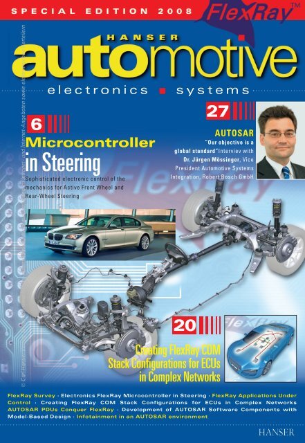
6<br />
electronics<br />
Microcontroller<br />
in Steering<br />
Sophisticated electronic control of the<br />
mechanics for Active Front Wheel and<br />
Rear-Wheel Steering<br />
systems<br />
27<br />
AUTOSAR<br />
“Our objective is a<br />
global standard”Interviev with<br />
Dr. Jürgen Mössinger, Vice<br />
President Automotive Systems<br />
Integration, Robert Bosch GmbH<br />
20<br />
Creating FlexRay COM<br />
Stack Configurations for ECUs<br />
in Complex Networks<br />
FlexRay Survey · Electronics FlexRay Microcontroller in Steering · FlexRay Applications Under<br />
Control · Creating FlexRay COM Stack Configurations for ECUs in Complex Networks<br />
AUTOSAR PDUs Conquer FlexRay · Development of AUTOSAR Software Components with<br />
Model-Based Design · Infotainment in an AUTOSAR environment
© Carl Hanser Verlag, München www.hanser-<strong>automotive</strong>.de Nicht zur Verfügung im Intranet- und Internet-Angeboten sowie elektronischen Verteilern
© Carl Hanser Verlag, München www.hanser-<strong>automotive</strong>.de Nicht zur Verfügung im Intranet- und Internet-Angeboten sowie elektronischen Verteilern<br />
Measuring in Rough Environments –<br />
Sensor Close, Synchronous, and<br />
Accurate<br />
ES400 Measurement Modules<br />
Compact and rugged for sensor<br />
close installation, IP67 protection,<br />
extended temperature range<br />
-40...120 °C<br />
Powerful time-synchronous data<br />
acquisiton for accurate measurements<br />
of signals from different<br />
sources<br />
Integrated with all established development<br />
and measuring systems:<br />
INCA, CANape, PROVEtech:VA,<br />
MM6, DEWESoft<br />
ES400 modules cover all relevant<br />
applications:<br />
– ES410 – A/D Module<br />
– ES411 – A/D Module with<br />
Sensor Power Supply<br />
– ES420 – Thermo Module<br />
– ES430 – Lambda Module<br />
– ES441 – Counter and Frequency<br />
Module with Sensor<br />
Power Supply<br />
ETAS Group<br />
Whether you’re looking to<br />
shorten your development<br />
times or reduce your warranty<br />
costs – the ETAS Group<br />
has an answer.<br />
We supply a comprehensive<br />
portfolio of standardized<br />
development and diagnostic<br />
tools that cover the entire life<br />
cycle of electronic control<br />
units, from development to<br />
operational use and service.<br />
ETAS GmbH<br />
Borsigstraße 14<br />
70469 Stuttgart, Germany<br />
Phone +49 711 89661- 0<br />
Fax +49 711 89661-106<br />
sales.de@etas.com<br />
www.etas.com
© Carl Hanser Verlag, München www.hanser-<strong>automotive</strong>.de Nicht zur Verfügung im Intranet- und Internet-Angeboten sowie elektronischen Verteilern<br />
ECU<br />
Calibration<br />
Experience with series projects.<br />
Choose proven FlexRay solutions.<br />
Take advantage of our extensive experience with FlexRay series<br />
projects. Use Vector’s comprehensive product portfolio for your<br />
FlexRay networking:<br />
> Simulate and test ECUs and networks with the sophisticated<br />
development environment CANoe and the FlexRay interfaces.<br />
> Profit from standardized ECU software. Vector software<br />
modules can be flexibly configured and easily integrated.<br />
> Ensure advantages in both quality and time: Rely on professional<br />
support during development and training.<br />
Get FlexRay on the road - with series-proven tools, scalable<br />
modules and 20 years of Vector networking know-how.<br />
Get on board: www.flexray-solutions.com<br />
Get the FlexRay Reference<br />
Chart now!<br />
www.flexray-solutions.com<br />
Vector Informatik GmbH<br />
Ingersheimer Str. 24<br />
70499 Stuttgart, Germany<br />
Tel. +49 (0) 7 11/80670-0<br />
www.vector-informatik.com
© Carl Hanser Verlag, München www.hanser-<strong>automotive</strong>.de Nicht zur Verfügung im Intranet- und Internet-Angeboten sowie elektronischen Verteilern<br />
FLEXRAYl AUTOMOTIVE 2008l3<br />
FlexRay<br />
for passenger<br />
cars only?<br />
The next car to feature the fully equipped FlexRay<br />
network in series is on its way – the second time<br />
this technology has gone into series production in<br />
the <strong>automotive</strong> sector. Its capability is proven. This news,<br />
of course, also spreads to other industries: interest in<br />
FlexRay is growing.<br />
Dietmar Millinger<br />
Elektrobit Austria GmbH,<br />
A-1060 Wien<br />
The FlexRay consortium has invested a<br />
great deal in the technology for the <strong>automotive</strong><br />
industry and has therefore done<br />
its bit. Every company in the consortium<br />
is entitled to do its own bit by equipping<br />
their own vehicles. But how shall the consortium<br />
benefit when third parties wish to<br />
use FlexRay? At the very least, it profits<br />
when FlexRay products and solutions are<br />
more widespread so they mature and<br />
improve. At the moment, using FlexRay is<br />
contractually defined for <strong>automotive</strong> applications<br />
only. Many interested parties from<br />
other industries, it is not clear what this<br />
precisely means.<br />
So, I will take a look on the Internet to<br />
find a definition for “<strong>automotive</strong>”.<br />
But, wait, SAE (http://www.sae.org/about/general/history/)<br />
already has a definition for “<strong>automotive</strong>”, maybe this provides<br />
some help . . .<br />
5 Minutes<br />
Should FlexRay be open to other<br />
industries? In our online survey we<br />
want to know, how you think about it.<br />
Join in for the questionnaire on<br />
www.hanser-<strong>automotive</strong>.de.<br />
The survey is completely anonymous<br />
and takes about five minutes.
© Carl Hanser Verlag, München A Uwww.hanser-<strong>automotive</strong>.de T O S A R Nicht zur Verfügung im Intranet- und Internet-Angeboten F L sowie E Xelektronischen R A Y Verteilern<br />
CONTENT<br />
4l SPECIAL EDITION FLEXRAYl AUTOMOTIVE 2008<br />
3 FlexRay, for passenger cars only?<br />
Preface from Dr. Dietmar Millinger, EB<br />
6 NEC Electronics FlexRay Microcontroller in<br />
Steering<br />
Dipl-Ing. Holger Schmerling, Dr. Costas Rente, Dipl-Ing. Sascha Galati<br />
Active (front wheel) Steering and Rear-Wheel Steering demands a<br />
very sophisticated control of torque and rotation of the actuator<br />
motors. Therefore the electronic Control of the Steering Mechanics<br />
with an Active Steering ECU and the Rear-Wheel Steering ECU<br />
10 dSpace: FlexRay Applications Under Control<br />
Dr. Ralf Stolpe, Dipl.-Ing. (FH) Björn Müller, Dipl. Inform. Joachim<br />
Stroop, Dipl.-Ing. André Rolfsmeier, Dipl.-Ing. (FH) Thorsten Hufnagel<br />
Combining FlexRay simulations with XCP on FlexRay<br />
16 Fujitsu: A Distributed Navigation Application<br />
enabled by FlexRay<br />
Fujitsu Microelectronics Europe and University of Applied Sciences<br />
Aschaffenburg (Prof. Dr.-Ing. J. Abke, Christian Eyrich,Matthias<br />
Steeg, Wolfgang Wiewesiek) Is FlexRay suitable for use in a navigation<br />
system? Can FlexRay be used to transfer moving image data<br />
between applications? A feasibility study has been undertaken to<br />
answer these questions in relation to a navigation application.<br />
20 TTTech Computertechnik AG: Creating FlexRay<br />
COM Stack Configurations for ECUs in Complex<br />
Networks<br />
Dipl.-Ing.Georg Stöger The allocation challenge of the FlexRay buffer<br />
memory.<br />
24 Vector Informatik and Audi AG: AUTOSAR PDUs<br />
Conquer FlexRay<br />
Dipl.-Ing. (FH) Wolfgang Brandstätter, Dr. rer. nat. Carsten Böke<br />
FlexRay Tools successfully support developments with PDU-based<br />
communications<br />
27 AUTOSAR: “Our objective is a global standard”<br />
Interview with Dr. Jürgen Mössinger, Vice President Automotive<br />
Systems Integration Robert Bosch GmbH, spokesperson of<br />
AUTOSAR until September 2008.<br />
29 The Mathworks: Development of AUTOSAR Software<br />
Components with Model-Based Design<br />
Guido Sandmann, Joachim Schlosser Top Down and Bottom up:<br />
From an architecture model to an AUTOSAR software component<br />
and reusing legacy models to generate AUTOSAR-compliant code<br />
31 OpenSynergy GmbH: Infotainment in an AUTO-<br />
SAR environment<br />
Dipl.-Ing. Frank-Peter Böhm, Dipl.-Ing. Rolf Morich, Dr. Stefaan Sonck<br />
Thiebaut AUTOSAR can be applied to typical vehicle functions, but it<br />
excludes precisely those areas which are most driven by the entertainment<br />
and telecommunications industries and in which customers<br />
experience innovations most directly and immediately.<br />
6<br />
Two ECUs directly affect the steering characteristics<br />
of the new BMW 7. A very<br />
sophisticated control of torque and rotation<br />
of the actuator motors requires a high<br />
precision closed loop control of the electrical<br />
BLDC motor. This is realized by a<br />
microcontroller that is able at the same<br />
time to frequently update information on<br />
motor currents and position, calculate and<br />
generate the corresponding PWM pattern<br />
required to drive the motor.<br />
This article describes the approach<br />
taken by a tool-based solution to compute<br />
and generate a buffer configuration<br />
and FlexRay Interface (FRIF) layer<br />
schedule that takes into account the<br />
limited resources of communication<br />
buffers and CPU time.<br />
29<br />
20<br />
Companies usually have an<br />
extensive library of mature and<br />
extensively tested models. It is<br />
important that these models<br />
can be reused to target different<br />
platforms such as AUTO-<br />
SAR without any changes to the<br />
models’ blocks.
© Carl Hanser Verlag, München www.hanser-<strong>automotive</strong>.de Nicht zur Verfügung im Intranet- und Internet-Angeboten sowie elektronischen Verteilern
© Carl Hanser Verlag, München www.hanser-<strong>automotive</strong>.de Nicht zur Verfügung im Intranet- und Internet-Angeboten sowie elektronischen Verteilern<br />
6lA UTOMOTIVE 2008l SPECIAL EDITION FLEXRAY<br />
NEC FlexRay Microcontroller<br />
in Steering<br />
NEC Electronics anticipated the demand for high performance<br />
microcontrollers with embedded FlexRay for chassis applications<br />
and started the development of the V850E/PHO3 in<br />
2004. Consequently, the PHO3 was the world-wide first<br />
microcontroller with embedded FlexRay to successfully pass<br />
the FlexRay Conformance Test at TÜV Nord.<br />
One major highlight of the new BMW 7 Series car<br />
model is its innovative chassis combining comfort,<br />
driving pleasure and active safety. The so-called<br />
Integral Active Steering concept is a symbiosis of electro-hydraulic<br />
power steering controlling the steering force,<br />
Active Steering (AS) controlling the steering angle via an<br />
overriding drive and the optional Rear-Wheel Steering,<br />
Clearly a good coordination of these systems is needed to<br />
ensure an optimum steering behavior in all driving situations.<br />
This is done by the integrated chassis management<br />
(ICM) module and means the ICM needs to have close<br />
communication links to the actor systems.<br />
Actio - reactio: The dynamics of a chassis with its mechanically<br />
coupled components is determined by physics’<br />
laws. Physics occur in real-time and do not care about bottlenecks<br />
such as bus protocols with limited bandwidth, high<br />
bus loads and unpredictable latencies. Therefore the need<br />
to control such a dynamic system via a network requires a<br />
high level of performance communication protocol. It is<br />
vital that it is able to keep pace with real-time requirements<br />
and cope with the amount of sensor data and actuator<br />
instructions.
© Carl Hanser Verlag, München www.hanser-<strong>automotive</strong>.de Nicht zur Verfügung im Intranet- und Internet-Angeboten sowie elektronischen Verteilern<br />
The introduction of FlexRay as the<br />
new high performance <strong>automotive</strong><br />
network protocol has paved the<br />
way for such an integrated chassis<br />
management system to efficiently<br />
control the interaction of distributed<br />
chassis functions (Fig. 1).<br />
Active Steering (AS)<br />
For the Active Steering a special<br />
gear is inserted into the column between<br />
the steering wheel and associated<br />
mechanics. Depending on the<br />
driving situation the impact of the<br />
steering wheel motion on the effective<br />
steering angle of the wheels can<br />
be changed by the AS. At slow city<br />
traffic (e.g at parking) the number of<br />
required steering wheel motions is<br />
reduced in order to make handling<br />
far more efficient. At higher speeds<br />
the steering behavior becomes<br />
more indirect, therefore the driver<br />
does not risk losing control of the<br />
vehicle as a result of unexpected<br />
and sudden steering wheel<br />
motions.<br />
Rear-Wheel Steering<br />
This is managed by means of a concentrically<br />
arranged brushless DC<br />
motor, which is positioned on the<br />
rear axle and moves the track rod<br />
through a spindle drive. The angle of<br />
the rear wheel can be controlled in<br />
a range of 3° maximum in both<br />
directions.<br />
For vehicle speeds of below 60<br />
km/h the rear wheels turn in the<br />
opposite direction of the front<br />
wheels thus enhancing the agility<br />
of the car. When driving at higher<br />
speeds the rear wheels steer in the<br />
same direction as the front wheels thus achieving a better<br />
balance of the side forces between front- and rear-wheels.<br />
This way the stability of the car improves e.g. for an evasive<br />
maneuver whilst driving on the motorway.<br />
Electronic Control of the Mechanics<br />
Both the Active Steering ECU and the Rear-Wheel Steering<br />
ECU directly affect the steering characteristics of the car.<br />
This demands a very sophisticated control of torque and<br />
rotation of the actuator motors. To achieve this a high precision<br />
closed loop control of the electrical BLDC motor is<br />
required. In order to facilitate this a microcontroller is<br />
necessary. This microcontroller is able at the same time to<br />
frequently update information on motor currents and position,<br />
calculate and generate the corresponding PWM pattern<br />
required to drive the motor.<br />
SPECIAL EDITION FLEXRAYl AUTOMOTIVE 2008l7<br />
Fig. 1: Integral Active Steering FlexRay network<br />
Fig. 2: Integral Active Steering ECU<br />
© <strong>automotive</strong><br />
© <strong>automotive</strong><br />
Typically the key components of such an ECU are as follows:<br />
- Main Microcontroller: For AS and Rear-Wheel Steering<br />
this is the NEC Electronics V850E/PHO3, responsible for<br />
the BLDC motor control, sensor evaluation, FlexRay communication<br />
and diagnosis.<br />
- Monitoring microcontroller: required for application monitoring.<br />
- Power MOSFETs to convert the logical PWM output signals<br />
into high currents are required to drive a powerful<br />
BLDC motor.<br />
- Sensor electronics for reading the position of the motor<br />
anchor and the individual phase currents.<br />
- FlexRay bus interface.<br />
- Power supplies.
© Carl Hanser Verlag, München www.hanser-<strong>automotive</strong>.de Nicht zur Verfügung im Intranet- und Internet-Angeboten sowie elektronischen Verteilern<br />
All this had to be realized in a<br />
compact ECU (Fig. 2) that can<br />
operate within harsh environmental<br />
conditions. Some of the<br />
challenging factors are: limited<br />
mounting space, high ambient<br />
temperatures due to the power<br />
dissipation of the MOSFETS and<br />
strict EMC requirements.<br />
Also the software becomes a lot<br />
more complex than before and<br />
requires more memory and<br />
more calculation performance(e.g.<br />
for the Flexray protocol<br />
stack).<br />
8lA UTOMOTIVE 2008l SPECIAL EDITION FLEXRAY<br />
The microcontroller - V850E/PHO3<br />
A microcontroller that is able to satisfy all the above mentioned<br />
requirements is a rare thing. Taking into consideration<br />
NEC’s very well known high level of quality and long<br />
expertise in the chassis field (e.g. several million microcontrollers<br />
sold for electrical power steering) it was decided<br />
to use NEC’s V850E/PHO3 for the Active Steering and<br />
Rear-Wheel Steering projects (Fig. 3).<br />
In a “nutshell” the PHO3 features a high level of calculation<br />
power, a huge memory (1 MB), the capability to control<br />
BLDC motor actuators, an interface to the FlexRay network,<br />
is able to support the extended <strong>automotive</strong> temperature<br />
range (A2 grade) plus excellent EMC performance.<br />
In addition an integrated floating point unit has been implemented<br />
as this is required to support today’s approach of<br />
model based algorithm development.<br />
Many chassis applications have similar requirements to<br />
those above , but require more or less performance, resp.<br />
more or less memory. To cover this, NEC have created a<br />
dedicated product line, named “P” Series. The “P” series<br />
offers strong solutions for low, mid and high-end chassis<br />
applications.<br />
Key parameters of the FlexRay Network<br />
The FlexRay network is the key component which facilitates<br />
the fast exchange of data. This makes it possible for the<br />
actuators to behave in a coordinated way and demonstrate<br />
optimized quick reactions to compliment the physics of<br />
driving.<br />
As the FlexRay protocol was designed to allow a high flexibility<br />
a huge amount of parameters have to be chosen.<br />
One key parameter is the cycle time. As the FlexRay configuration<br />
should be unchanged for all cars within the 7<br />
Series platform and also future car series, it was a very difficult<br />
task to find the optimum balance required between<br />
network throughput and network load.<br />
Initially it was felt beneficial to have a high frequency of<br />
messages. But this would mean that seldomly sent messages<br />
would waste the network capacity. Finally it was<br />
decided to use a 10 Mbit transfer rate and 5 ms cycle time<br />
within the static and dynamic segments over a single channel.<br />
Although a network based purely on a passive bus<br />
would be preferable from cost<br />
point of view, it was finally decided<br />
to use a combination between the<br />
passive bus and star coupler. This<br />
was chosen because too many<br />
FlexRay nodes connected to one<br />
cable would detoriate the signal<br />
quality and hence limit the achievable<br />
bandwidth and quality of the<br />
signal transmission.<br />
V850E/PHO3 with Flex-<br />
Ray is running - What is<br />
next?<br />
Fig. 3: NEC V850E/PHO3 microcontroller<br />
As a result of the successful introduction<br />
of FlexRay into the first<br />
series project, other OEMs are now following and will present<br />
cars with FlexRay over the next couple of years. This<br />
means that FlexRay has been established as the <strong>automotive</strong><br />
high performance communication protocol and will<br />
become a standard interfaces within the <strong>automotive</strong> mass<br />
market. In order to support FlexRay for broader application<br />
areas the topology of the FlexRay network has to become<br />
much simpler. Also more flexible concepts are required<br />
e.g. synchronization. This is already on the way with the<br />
FlexRay protocol specification 3.0.<br />
The next big challenge for future chassis ECU’s will be cost<br />
reduction. High optimization potential still can be found in<br />
simplification of the functional safety concepts, by applying<br />
microcontrollers with enhanced functional safety support.<br />
This could help eliminating or at least simplifying components<br />
such as additional monitoring microcontrollers or<br />
supervision ASICs. But it could also dramatically reduce<br />
the efforts on the SW engineering side.<br />
Why not focus on the actual application SW and have the<br />
HW perform all of the diagnostics still being done in SW<br />
like memory tests, core self tests and plausibility check of<br />
safety-relevant calculation results? And why not reduce the<br />
efforts for functional safety validation and the assessment<br />
process in the same way?<br />
Wouldn’t it be a relief to present an “out-of-the-box” selfsafe<br />
microcontroller with proven safety integrity level rather<br />
than generating a new FMEA for each ECU variant,<br />
even though the same microcontroller is used?<br />
All this could be addressed by a generic functional safety<br />
concept for the microcontroller saving tremendous efforts to<br />
set up and validate a new functional safety concept for each<br />
and every product line. NEC Electronics has already started<br />
designing a new chassis microcontroller family, the Px4<br />
Series to meet these demands. It will be optimized for <strong>automotive</strong><br />
applications targeting IEC 61508 SIL3 certification<br />
and will use a single microcontroller to cover the span between<br />
a high level of functional safety at minimal costs. NEC<br />
has established a close cooperation with TÜV SÜD to monitor<br />
and assess the development of Px4 from the early conceptual<br />
phase to the final implementation in silicon.<br />
V850E/Px4 will feature an integral safety concept based on<br />
two redundant CPU subsystems checking simultaneous<br />
each others’ operation.
© Carl Hanser Verlag, München www.hanser-<strong>automotive</strong>.de Nicht zur Verfügung im Intranet- und Internet-Angeboten sowie elektronischen Verteilern<br />
It will be accomplished by additional hardware diagnostics<br />
addressing those failure modes that need to be addressed<br />
in diagnostic SW or even external hardware today.<br />
From a performance point of view V850E/Px4 will expand<br />
the existing “P” Series roadmap and will feature greater<br />
calculation power due to the new superscalar E2 CPU core,<br />
plus an enhanced peripheral set which is tailored to meet<br />
future chassis application requirements. A full feature list<br />
can be downloaded from Internet:www.eu.necel.com/<br />
applications/<strong>automotive</strong>/040_flexray<br />
Though planned to be manufactured in a state-of-the-art<br />
90nm process, the V850E/Px4 will also use a proven-in-thefield<br />
predecessor device as starting point for the new<br />
design - V850E/PHO3. The realization of this first NEC<br />
microcontroller with embedded FlexRay interface would<br />
not have been possible without the extremely close collaboration<br />
of BMW and the excellent strong team spirit that<br />
prevailed between both parties.<br />
Finally NEC would like to take this opportunity to thank all<br />
of the involved people, particularly the project teams at the<br />
BMW Group – both for a successful introduction of this<br />
device to the market and also for the drive and inspiration<br />
to tackle challenging new <strong>automotive</strong> market requirements.<br />
SPECIAL EDITION FLEXRAYl AUTOMOTIVE 2008l9<br />
Dipl-Ing. Holger Schmerling studied electrical<br />
engineering at the Cologne University of<br />
Applied Sciences specializing in communication<br />
systems. For the past 6 years he has<br />
worked as an application engineer on Flex-<br />
Ray, TTCAN and AUTOSAR in the NEC Electronics<br />
Automotive Business Unit in Düsseldorf.<br />
Dipl-Ing. Sascha Galati studied electrical engineering<br />
at the University of Wuppertal with focus<br />
on automation technology. He gained 4 years<br />
experience as application engineer for <strong>automotive</strong><br />
microcontrollers before joining the NEC Automotive<br />
Business Unit in 2003. Now he is technical<br />
product responsible for <strong>automotive</strong> chassis<br />
microcontroller products.<br />
Dr. Costas Rente studied Physics at the<br />
RWTH Aachen University. In his promotion<br />
thesis he developed semiconductor detectors<br />
for high energy physics. Since 2000 he is<br />
with NEC Electronics and now active in the<br />
project management of chassis products for<br />
the <strong>automotive</strong> market.
© Carl Hanser Verlag, München www.hanser-<strong>automotive</strong>.de Nicht zur Verfügung im Intranet- und Internet-Angeboten sowie elektronischen Verteilern<br />
10lA UTOMOTIVE 2008l SPECIAL EDITION FLEXRAY<br />
COMBINING FLEXRAY SIMULATIONS WITH XCP ON FLEXRAY<br />
FlexRay Applications<br />
Under Control<br />
Following the first successful use of FlexRay in a production application,<br />
numerous further projects are presently approaching production level. The<br />
test functions necessary for verifying these systems are made available by<br />
test systems that have been successfully applied in many projects. Other<br />
FlexRay functions in addition to ones for network verification also came<br />
into operation. Along with FlexRay, the Universal Measurement and Calibration<br />
Protocol, XCP, is also gaining in importance. This paper describes<br />
the methods being used for FlexRay simulations and provides an XCP on<br />
FlexRay application example.<br />
Setting up a FlexRay Simulation<br />
In-vehicle networks are in a state of constant further<br />
development, particularly since the announcement of<br />
FlexRay in the year 2000. dSPACE GmbH was one of the<br />
companies that got involved in developing tools for Flex-<br />
Ray at an early stage, in response to the need for comprehensive<br />
means of testing the new bus system. Vehicles<br />
have now been going into series production with<br />
FlexRay for over a year, and further vehicles and applications<br />
are just one step away from being launched on<br />
the market. It is clear that FlexRay will continue to<br />
advance rapidly.<br />
As the number of applications grows, so do the requirements<br />
on the necessary test tools and infrastructures. Building<br />
on the experience gained from previous applications,<br />
these tools must be given further test execution functions.<br />
The dSPACE solution for testing FlexRay is based on<br />
various hardware platforms and the FlexRay Configuration<br />
Package. It already includes comprehensive test functions<br />
that were also used in the first production project.<br />
The dSPACE tool chain, with its real-time-capable simulation<br />
platforms and with MATLAB/Simulink modeling facilities,<br />
consists of several parts. The resulting workflow for<br />
configuring a test system is shown in Fig. 1.<br />
The dSPACE FlexRay Configuration Package is used to configure<br />
a dSPACE system as simulation or monitoring nodes<br />
in a FlexRay network. The nodes selected by the user are<br />
configured with the dSPACE FlexRay Configuration Tool<br />
according to a FIBEX communication matrix containing<br />
scheduling information for signals and frames. Various<br />
views help in managing the FlexRay configuration. The tool<br />
uses the configuration to generate communication code<br />
and parameters for the FlexRay controllers (called CHI<br />
code). The communication information is extracted and
© Carl Hanser Verlag, München www.hanser-<strong>automotive</strong>.de Nicht zur Verfügung im Intranet- und Internet-Angeboten sowie elektronischen Verteilern
© Carl Hanser Verlag, München www.hanser-<strong>automotive</strong>.de Nicht zur Verfügung im Intranet- und Internet-Angeboten sowie elektronischen Verteilern<br />
12lA UTOMOTIVE 2008l SPECIAL EDITION FLEXRAY<br />
transferred to MATLAB/Simulink, where the data is used<br />
as parameters for FlexRay communication blocks from the<br />
RTI FlexRay Configuration Blockset. Application-specific<br />
Simulink models can be created using the RTI FlexRay Configuration<br />
Blockset as a basis, with data provided by the<br />
configuration tool. The block attributes are filled with data<br />
generated by the dSPACE FlexRay Configuration Tool. The<br />
blockset contains additional blocks that can be used for<br />
task execution control, interrupt and error handling, status<br />
information, and controller reset. The hardware is connected<br />
via the FlexRay interface to the FlexRay bus, and from<br />
there to the FlexRay ECUs which are the units under test.<br />
The FlexRay Configuration Package is not<br />
only concerned with simple restbus<br />
simulation for mimicking the network<br />
behavior, but also allows target-oriented<br />
failure simulation by checking potential<br />
failure cases. For example, the package<br />
can be used to insert logical corruptions<br />
in FlexRay communication to allow a<br />
cyclic FlexRay frame to be switched in or<br />
out, CRC algorithms to be switched<br />
during run time, etc.<br />
In addition, it is also possible to have a failure<br />
insertion on the physical level by<br />
simulating broken wires, short circuits,<br />
etc., or to vary the termination resistance.<br />
This can be done with suitable failure<br />
insertion hardware for differential<br />
busses.<br />
The dSPACE FlexRay Configuration Tool<br />
can create several kinds of time-triggered<br />
tasks for the various scenarios. In addition<br />
to these test functions for FlexRay<br />
networks, the tool can also be used in<br />
connection with the RTI Bypass Blockset<br />
and the Universal Measurement and<br />
Calibration Protocol (XCP). XCP is the successor to the<br />
much-used CAN Calibration Protocol (CCP). The advantage<br />
of XCP is that it provides strict separation between the protocol<br />
and the transport level, and is therefore open for the<br />
implementation of FlexRay or even future bus systems.<br />
XCP on FlexRay is part of the XCP family standardized by<br />
ASAM. The XCP concept is based on the master/slave principle,<br />
with the electronic control unit (ECU) as the slave.<br />
XCP on FlexRay is already being used in numerous projects,<br />
especially where the CAN bus has been replaced by<br />
FlexRay.<br />
Task-Synchronous Bypassing via XCP<br />
on FlexRay<br />
Due to the complexity of modern electronic control units<br />
(ECUs) and the limited time available for the development<br />
of new ECU generations, the entire ECU software is developed<br />
from scratch in only very few cases. Instead the existing<br />
ECU code is adapted or extended. The external<br />
bypass method is an efficient approach in this context, allowing<br />
new algorithms to be developed on a rapid prototyping<br />
system while the original ECU executes all the functions<br />
that remain unchanged. The input and output variables<br />
of the bypass model are exchanged, and task execution<br />
on the ECU and the prototyping system is synchronized<br />
via existing ECU interfaces such as XCP on FlexRay.<br />
The external bypass approach gives the greatest flexibility<br />
possible during the design phase, since there are almost<br />
no resource constraints such as RAM, ROM, processor<br />
performance, or I/O channels. Real-time behavior is guaranteed<br />
even for complex bypass functions. In addition, the<br />
autoboot options of the prototyping systems allow the<br />
behavior of new functions to be validated in realistic scenarios,<br />
for example during test drives.<br />
Fig. 1: Workflow with dSPACE’s FlexRay solution.<br />
© <strong>automotive</strong><br />
In this configuration example, the dSPACE MicroAutoBox<br />
is used as a real-time prototyping system. The bypass function<br />
is calculated synchronously to an ECU task. As soon<br />
as all the input data of the bypass model is available, an<br />
interrupt is triggered and the bypass task on the MicroAutoBox<br />
is executed. Alternatively, task execution on the two<br />
systems can be synchronized by means of the FlexRay<br />
message schedule. Execution of the bypass task is then<br />
purely time-driven (Fig. 2).<br />
Real-Time ECU Access via XCP on Flex-<br />
Ray<br />
For developing ECU functions by means of the external<br />
bypass approach, it is usually necessary to configure the<br />
bypass interface in the modeling environment and to change<br />
the input and output signals of the bypass model<br />
without ECU code modifications. The RTI Bypass Blockset<br />
provides a generic user interface for this purpose, with the<br />
same look and feel no matter what ECU interface is actually<br />
used for bypassing.<br />
The XCP on FlexRay option of the RTI Bypass Blockset is<br />
based on the dSPACE FlexRay Configuration Package. The
Can you buy electronics system<br />
know-how to save time and money?<br />
© Carl Hanser Verlag, München www.hanser-<strong>automotive</strong>.de Nicht zur Verfügung im Intranet- und Internet-Angeboten sowie elektronischen Verteilern<br />
Yes<br />
With semiconductors, sensors and<br />
Intellectual Property, developed by Bosch<br />
Innovation from Bosch: Share the benefits of 40 years Bosch experience in development<br />
and manufacture of innovative electronic components for the <strong>automotive</strong> market.<br />
Our semiconductors, power semiconductors and sensors cover a wide range of<br />
<strong>automotive</strong> applications. Our IP modules make the integration of communication and<br />
general functions fast and easy. For additional information, please visit our website:<br />
www.bosch-semiconductors.com<br />
Visit our booth at:<br />
Convergence, Detroit: October 20-22, Booth #233<br />
electronica, Munich: November 11-14, Hall A6, Booth #340
© Carl Hanser Verlag, München www.hanser-<strong>automotive</strong>.de Nicht zur Verfügung im Intranet- und Internet-Angeboten sowie elektronischen Verteilern<br />
14lA UTOMOTIVE 2007l 2008l SPECIAL EDITION FLEXRAY<br />
Fig. 2:Task synchronization for bypass scenarios via XCP on FlexRay.<br />
Fig. 3: Workflow for function bypassing via XCP on FlexRay<br />
configuration tool in the package allows users to assign the<br />
XCP master node and to select and configure the XCP slots<br />
of the FlexRay cycle necessary for bypassing, using the<br />
information in the ASAM MCD2 FBX (FIBEX) file. A Simulink<br />
library is generated according to the FlexRay configuration.<br />
After that, the bypass model can be implemented.<br />
The appropriate blocks from the RTI Bypass Blockset are<br />
used for selecting a suitable XCP slot and associating it<br />
with variables to be read from and written to the ECU. The<br />
set of variables available for selection is provided by the<br />
ECU description (ASAP2) file. In addition, the RTI Bypass<br />
Blockset provides configuration dialogs for creating further<br />
ECU variables that were not described in the ASAP2 file<br />
and that can be used for read and write access (Fig. 3).<br />
The synchronization of the ECU and the rapid prototyping<br />
system can be implemented with the help of the FlexRay<br />
Message Schedule or the RTI bypass interrupt mechanism.<br />
© <strong>automotive</strong><br />
If the interrupt mechanism is used, the<br />
calculation of the bypass model is triggered<br />
as soon as all the input values are<br />
available as specified in the model. If<br />
the FlexRay Message Schedule is used,<br />
the calculation of the bypass model is<br />
time-driven regardless of the input<br />
values that were received up to that<br />
point. The RTI Bypass Blockset offers<br />
various mechanisms to ensure data<br />
consistency<br />
Apart from function development<br />
making use of the external bypass<br />
approach, also various hardware-in-theloop<br />
(HIL) test scenarios require realtime<br />
access to ECUs. In these cases,<br />
the RTI Bypass Blockset can also be<br />
used on the HIL platforms: for example,<br />
for real-time tests or to capture the ECU<br />
data for real-time plausibility tests.<br />
© <strong>automotive</strong><br />
Measurement and Calibration via XCP<br />
on FlexRay<br />
Adapting the ECU software to engine and vehicle variants<br />
and validating the vehicle behavior are important milestones<br />
during the ECU development process. These specific<br />
applications are supported by CalDesk, the universal measurement,<br />
calibration and diagnostic tool from dSPACE. For<br />
communication with ECUs via XCP on FlexRay, CalDesk<br />
provides an XCP master implementation that allows users<br />
to measure ECU-internal variables and to adjust calibration<br />
parameters in the ECU software via FlexRay. CalDesk also<br />
lets users record and analyze measurement data from the<br />
vehicle bus, external measurement modules, further ECUs<br />
and dSPACE real-time systems. It is also possible to simultaneously<br />
adjust parameters on different platforms. In addition,<br />
typical diagnostic tasks such as reading and resetting<br />
the ECU’s fault memory via dedicated instruments are sup-
© Carl Hanser Verlag, München www.hanser-<strong>automotive</strong>.de Nicht zur Verfügung im Intranet- und Internet-Angeboten sowie elektronischen Verteilern<br />
FLEXRAYl AUTOMOTIVE 2008l 15<br />
ported. Measurement, calibration and diagnostic tasks can<br />
be remote-controlled via an ASAM MCD3-compliant<br />
COM/DCOM interface: for example, via MATLAB or AutomationDesk<br />
for ECU tests.<br />
Summary<br />
The examples in the previous sections show some basic<br />
concepts for the efficient simulation of FlexRay networks<br />
for ECU tests. The described methods are already being<br />
used in many customer projects and are based on dSPA-<br />
CE’s proven hardware and software simulation solutions.<br />
The capabilities and possibilities of dSPACE’s comprehensive<br />
tool portfolio were explained using an example of<br />
bypassing via XCP on FlexRay. In addition, the paper described<br />
the interaction of the FlexRay configuration tool with<br />
the RTI blocks, as well as with the experiment environments<br />
and tools for test automation.<br />
This high level of performance in customer projects is already<br />
assisting developers as they handle their test, measurement<br />
and calibration tasks in FlexRay projects.<br />
Dr. Ralf Stolpe has been working at dSPACE<br />
GmbH since 2000, and is responsible for projects<br />
pertaining to the development of Flex-<br />
Ray tools.<br />
Dipl.-Ing. (FH) Björn Müller has been a product<br />
engineer in the Hardware-in-the-Loop<br />
Simulator Team since 2006, where he is<br />
responsible for the bus system products of<br />
dSPACE GmbH.<br />
Dipl. Inform. Joachim Stroop is the Lead<br />
Product Manager for System and Function<br />
Design Tools at dSPACE GmbH.<br />
Dipl.-Ing. André Rolfsmeier is Senior Product<br />
Manager for ECU Calibration and Bypassing<br />
at dSPACE GmbH and, as such, is<br />
responsible for measurement and calibration<br />
interfaces in the dSPACE tool portfolio.<br />
Dipl.-Ing. (FH) Thorsten Hufnagel is Project<br />
Leader for ECU Interface and Bypassing<br />
systems at dSPACE GmbH.<br />
Right away –<br />
with FlexRay!<br />
DTS and EDICflex –<br />
the perfect solution for diagnostics and<br />
flash programming of FlexRay ECUs<br />
No matter whether in development, validation<br />
or production – EDICflex hardware interfaces<br />
allow reliable ECU communication at any time.<br />
The Embedded Diagnostic Module guarantees<br />
robust realtime behaviour in diagnostic and<br />
flash programming applications.<br />
Benefit from DTS solutions also in your<br />
applications – flexible user interfaces and<br />
automation APIs are ready for you.<br />
Contact us now!<br />
Tel.: +49 (89) 456 56 420, www.softing.com
© Carl Hanser Verlag, München www.hanser-<strong>automotive</strong>.de Nicht zur Verfügung im Intranet- und Internet-Angeboten sowie elektronischen Verteilern<br />
20lA UTOMOTIVE 2008l SPECIAL EDITION FLEXRAY<br />
Creating FlexRay COM Stack<br />
Configurations<br />
A FlexRay controller typically offers, or addresses via DMA access, several<br />
kilobytes of buffer memory. AUTOSAR defines a comprehensive set of layers<br />
to manage FlexRay communication in an ECU, from high-level signal<br />
management in the COM and handling of large data packets in the Transport<br />
Protocol layer down to the FlexRay Interface Layer for management of<br />
real-time interfaces and the hardware abstraction in the FlexRay Driver<br />
layer. But how can we efficiently allocate the FlexRay buffer memory of an<br />
ECU to the communication frames transmitted and received by an ECU?<br />
How does this affect the CPU load of this ECU, considering that each access<br />
to a communication buffer creates some work for the CPU?<br />
The Allocation Challenge<br />
The challenge itself is illustrated by an example: Assume<br />
a “telephone service” shop where 10 telephone<br />
booths are available for customer use and we are<br />
responsible for assigning customers to phones. Customers<br />
can “transmit” by making phone calls there, or<br />
“receive” by taking incoming calls there. How can we<br />
ensure that the use of the booths is optimized?<br />
Since we know our customers, we try to plan ahead: We<br />
have to exclusively reserve a booth for each of our “very<br />
important” customers. Whenever they require a phone,<br />
for ECUs in Complex<br />
Networks<br />
we need to have a phone booth available for them. Some<br />
customers are known for their short phone calls, usually no<br />
more than a few minutes. With regard to this additional<br />
information or “constraints”, we are able to develop efficient<br />
strategies for allocating phones to the customers.<br />
This illustrates the challenge that needs to be solved for<br />
complex real-time networks: We have a limited number of<br />
buffers (phone booths) and a large number of communication<br />
frames (customers), transmitted or received by the<br />
FlexRay communication controller (the shop) of our ECU.<br />
The buffers have to be allocated to the frames in a way so
© Carl Hanser Verlag, München www.hanser-<strong>automotive</strong>.de Nicht zur Verfügung im Intranet- und Internet-Angeboten sowie elektronischen Verteilern<br />
that no information is lost (this happens if no buffer is free<br />
upon reception) or unduly delayed (this happens if no buffer<br />
is available when a transmission has to be made).<br />
Optimization Goal of AUTOSAR<br />
An additional constraint is related to how AUTOSAR handles<br />
the FlexRay communication: The interface handling the<br />
access to the FlexRay buffers, called the FlexRay Interface<br />
Layer (FrIf), is a software layer executed at certain pre-defined<br />
times and with certain pre-defined actions (“jobs”)<br />
such as packing and unpacking data. It is like the manager<br />
at the phone booth shop: he has some<br />
overhead getting up to assign a customer<br />
to a booth. If there are many booths<br />
and many customers, it would be more<br />
efficient to do several assignments in<br />
one step. These actions correspond to<br />
task activation in an ECU. If the FrIf has<br />
to be activated for each job (e.g. transmission<br />
or reception of a PDU), a lot of<br />
CPU time will be spent just on FrIf activations.<br />
It reduces the overhead significantly<br />
if we can group these jobs.<br />
A FlexRay communication controller<br />
offers dozens or hundreds of buffers,<br />
depending on the hardware and, in some<br />
cases, on the length of the messages.<br />
But several dozens or several hundred<br />
FlexRay frames may have to be transmitted<br />
and received on this node. This is not<br />
a fictional scenario: Some ECUs such as gateways need to<br />
send or receive many of the frames on a network, and a nontrivial<br />
FlexRay system will usually contain hundreds of different<br />
frames. For many of these frames (“static frames”), the<br />
frequency, phase and order are exactly known from the Flex-<br />
Ray communication schedule, while for others (“dynamic<br />
frames”), this is not necessarily so.<br />
Even with a copious amount of communication buffers, the<br />
authors found that it is not a trivial task to find proper allocations<br />
for the buffers when implementing AUTOSAR configurations<br />
for ECUs sending and receiving significant<br />
SPECIAL EDITION FLEXRAYl AUTOMOTIVE 2008l21<br />
amounts of data in large FlexRay networks. As explained<br />
above, the challenge is to define the buffer allocation in a<br />
way that buffers are efficiently used, all frames can be<br />
received and transmitted in time, and the CPU load generated<br />
by the FlexRay Interface layer activations is kept to a<br />
reasonable minimum.<br />
Fig.1:The validity span of the buffers, shown for a period of the green and<br />
the blue PDU. When using 2 buffers for the frames in slot 2, there are just 4<br />
FRIF interrupts necessary.<br />
© <strong>automotive</strong><br />
Several Possibilities for Allocation<br />
The purpose of the buffer allocation is to assign message<br />
buffers to slots and channels, select the buffer direction<br />
(“transmit” or “receive”), and define cycle counter filtering:<br />
Like for CAN, a FlexRay communication buffer can be<br />
programmed to receive only frames with defined identifiers<br />
or identifier ranges, e.g. “receive frame ID 3” or<br />
“receive frame IDs in the range 0x10..0x1F”. FlexRay communication<br />
is organized in (strictly) 64 communication<br />
cycles, and the filtering can refer to these cycles too, e.g.<br />
“receive frame 3 in any communication cycle” or, alternatively,<br />
“receive frame 3 only in communication cycle 20”.<br />
To find a buffer for every frame sent or received by a node<br />
can be a rather simple task when support for the FlexRay<br />
Interface layer is not considered: In this case, one buffer<br />
Mobile drives Automotive.<br />
Today‘s consumers are digital natives who live their life connected<br />
via blogs, communities, and online games. They expect anything,<br />
anywhere, anytime, on any device.<br />
Get mobile in your car. www.tietoenator.com<br />
TietoEnator is a professional service company providing IT, R&D<br />
and consulting services.
© Carl Hanser Verlag, München www.hanser-<strong>automotive</strong>.de Nicht zur Verfügung im Intranet- und Internet-Angeboten sowie elektronischen Verteilern<br />
22lA UTOMOTIVE 2008l SPECIAL EDITION FLEXRAY<br />
Fig. 2: A valid whitelist has to be within the validity span of a buffer.<br />
can be assigned to each slot, independent of the frame<br />
received in that slot. The buffer then needs to be read in<br />
each communication cycle, and the number of buffers is an<br />
upper limit for the number of nodes in a communication<br />
cluster, because a buffer is not allowed to be assigned to<br />
more than one slot. This relaxes constraints quite a bit: we<br />
may have hundreds of frames, but only dozens of slots and<br />
the number of buffers typically is sufficient for this strategy.<br />
But is it always possible?<br />
Validity Spans and Grouping of FrIf Jobs<br />
The following example illustrates how the buffer allocation<br />
can support the optimal FlexRay Interface layer configuration<br />
with respect to CPU load. For demonstration we choose<br />
a single-channel FlexRay network schedule with 8<br />
cycles (instead of the full 64) and 8 static slots (instead of<br />
the several dozens that large FlexRay schedules have). As<br />
shown in the figure 1, there are 2 PDUs sent in this slot –<br />
the first one (green) is sent every odd cycle and the other<br />
one (blue) is sent every even cycle. Initially, all frames of<br />
one static slot for transmission (or reception) could share<br />
one buffer. The disadvantage with this approach is that one<br />
FlexRay Interface interrupt has to be raised in every communication<br />
cycle to copy the PDUs from the system<br />
memory into the controller buffers for transmission (or the<br />
other way round, for reception).<br />
If the real-time constraints for the PDUs allow, one FlexRay<br />
Interface interrupt per two cycles would be sufficient. For<br />
this, two buffers have to be used, and FlexRay controller<br />
configuration specifies when (i.e. in which slot and cycle)<br />
which buffer is to be sent. Such a “cycle filtering” configuration<br />
is specified by a “base cycle” parameter (the first<br />
transmission will occur in cycle N of the 64 cycles) and a<br />
“cycle repetition” parameter (the transmission will reoccur<br />
every N cycles throughout the 64 cycles) for each<br />
buffer. One FlexRay Interface job can now be executed in<br />
the beginning of every odd cycle, copying both PDUs to the<br />
corresponding buffers.<br />
In this example configuration, the “validity span” of each<br />
of these two buffers is “two cycles”: Each buffer can be<br />
updated in a time interval lasting two cycles, before the<br />
transmission is performed by the FlexRay controller, and<br />
new data needs to be provided. It is easier to compute a<br />
schedule for the jobs of a FrIf to operate on buffers with<br />
large validity spans, just as it is easier for humans to enter<br />
a slow-moving merry-go-round than a fast-moving one. And<br />
larger validity spans usually mean that more FrIf jobs can<br />
be grouped together, resulting in lower CPU usage for FrIf<br />
activations/context switches.<br />
Application Constraints and Automatic<br />
Scheduling<br />
A more sophisticated buffer allocation algorithm is required<br />
when the application has additional timing constraints<br />
about “when does the communication have to take place”.<br />
We assume a communication schedule where several relevant<br />
PDUs are transmitted in a single slot (X). As shown in<br />
figure 2,<br />
<br />
<br />
<br />
© <strong>automotive</strong><br />
PDU_A is transmitted with base cycle 0 and cycle<br />
repetition 4,<br />
PDU_B is transmitted with base cycle 0 and cycle<br />
repetition 1,<br />
PDU_C is transmitted with base cycle 1 and repetition<br />
2.<br />
Therefore, each frame in slot X contains 2 PDUs (in one<br />
case, one PDU is missing; this is “currently unused” frame<br />
space that can be used for later extensions to the schedule).<br />
In cycle 0 (with repetition 4), the frame contains PDUs<br />
A and B, in cycle 1 (with repetition 2!) the frame contains<br />
PDUs B and C, and in cycle 2 (with repetition 4), the frame<br />
contains just PDU B. Assuming an application is concerned<br />
with data in PDU_A and PDU_C, FlexRay data for this application<br />
will be received in 3 out of every 4 cycles. However,<br />
let’s say the application requires – here is the additional<br />
constraint (in complex systems there will be several of<br />
these) – that the AUTOSAR COM functions are only executed<br />
at the end of every second communication cycle.<br />
(Such a constraint is typically defined to ensure that legacy<br />
applications are not interrupted by basic software activations).<br />
Allocating one buffer for slot X is now forbidden,<br />
because we get new data in three out of four cycles, but<br />
we are not allowed to schedule one FlexRay Interface activation<br />
per cycle. Hence a smart buffer allocation algorithm<br />
is necessary to maximize the validity span of buffers: two
© Carl Hanser Verlag, München www.hanser-<strong>automotive</strong>.de Nicht zur Verfügung im Intranet- und Internet-Angeboten sowie elektronischen Verteilern<br />
buffers are used for slot X! BUFFER_A holds the frame with<br />
PDUs A and B (validity span: 4 cycles), and BUFFER_B<br />
holds the frame with PDUs B and C (validity span: 2 cycles).<br />
Now the FlexRay Interface activations can be successfully<br />
placed in an interval labeled “whitelist” in figure 2. Whitelists<br />
are used-definable intervals of time in the cycle, specifying<br />
when a PDU may be handled by the FrIf. Whitelists<br />
are often used to formulate application constraints for FrIf<br />
activities, in this case “process the PDUs only every<br />
second cycle”.<br />
In this example, no cycle filter mask can be defined which<br />
contains PDU_A and PDU_C and still meets the application<br />
constraint. Using several buffers for one slot, and configuring<br />
each of these buffers with appropriate cycle filtering,<br />
may be required to meet all constraints encountered in a<br />
typical AUTOSAR FlexRay ECU.<br />
Available Tool Support<br />
The combination of<br />
hardware constraints – how many buffers (and sometimes:<br />
which with restrictions regarding filtering) are<br />
available?<br />
network schedule constraints – when is which PDU<br />
available for reception/when does it have to be provided<br />
for transmission?<br />
application constraints – when, for whatever reason,<br />
shall the FrIf perform its FlexRay handling jobs for specific<br />
PDUs (whitelists) and when is it forbidden to execute<br />
any such jobs (blacklists)? Are there any buffers<br />
that must not be used because they are reserved for<br />
something else (e.g. a FIFO)?<br />
the goal for optimization – group FrIf activities as<br />
much as possible to reduce the CPU load from activations/context<br />
switches<br />
is managed by a scheduling algorithm that automatically<br />
computes at which times during each cycle which FrIf jobs<br />
have to be executed to fulfill all of these constraints. The<br />
tool performing this scheduling algorithm is called TTX-<br />
Build. In order to generate a FrIf schedule for an ECU, the<br />
TTX-Build FrIf scheduler gets as input<br />
<br />
<br />
<br />
<br />
the (often hundreds of) PDUs and frames on the Flex-<br />
Ray network (FIBEX file),<br />
the hardware definition of the FlexRay controller of<br />
the node (ECU definition),<br />
the specification which of the PDUs are to be sent or<br />
received by this ECU (node configuration), e.g. for<br />
AUTOSAR COM (signal based communication interface),<br />
NM (network management) or TP (transport<br />
protocol),<br />
application constraints in the form of time intervals for<br />
“do” and “don’t” execute FrIf actions (blacklists and<br />
whitelists).<br />
The resulting FrIf schedule contains as few as possible (to<br />
minimize the CPU overhead) but as many as necessary FrIf<br />
“tasks”, i.e. definitions of which activities the FrIf has to execute<br />
at certain points in time (referring to the FlexRay network<br />
time).<br />
FLEXRAYl AUTOMOTIVE 2008l 23<br />
A tool for generating and checking specific parts of ECU<br />
software and configuration data needs to support integration<br />
in a development tool chain, where it can be used either<br />
for manual (GUI) or automatic (batch mode) operation.<br />
In the FlexRay ecosystem, this means compatibility to welldefined<br />
input and output file formats to support the workflow<br />
and development processes suggested by AUTOSAR<br />
and established <strong>automotive</strong> electronics development processes.<br />
In case of TTXBuild, it reads the FlexRay cluster<br />
description and network schedule from a FIBEX (Field Bus<br />
Exchange Format) file, takes node configuration data from<br />
a GUI or a user-supplied database (including scripting support<br />
for automatic generation of such a database) and generates<br />
the configuration XML files as described in AUTO-<br />
SAR.<br />
Dipl.-Ing.Georg Stöger studied Realtime<br />
systems at TU Wien. Since 1998 he is working<br />
for TTTech Computertechnik AG, Vienna,<br />
Austria. Today, he is leading the Core Technology<br />
Unit.<br />
FlexConfig - design and<br />
configuration software<br />
for FlexRay.<br />
By Eberspächer Electronics.<br />
Comfortable graphical editors and wizards<br />
Lossless import, export and editing of FIBEX<br />
(1.2.0a, 2.0.0d, 2.0.1 and 3.0.0)<br />
Converter for FIBEX+ to FIBEX 3.0.0,<br />
FIBEX 2.0.1 to FIBEX 3.0.0, CANdb to<br />
FIBEX 2.0.1/3.0.0<br />
Support of PDUs<br />
CHI-exports for all major<br />
communication chips<br />
www.eberspaecher.com
© Carl Hanser Verlag, München www.hanser-<strong>automotive</strong>.de Nicht zur Verfügung im Intranet- und Internet-Angeboten sowie elektronischen Verteilern<br />
24lA UTOMOTIVE 2008l SPECIAL EDITION FLEXRAY<br />
FLEXRAY TOOLS<br />
SUCCESSFULLY SUPPORT<br />
DEVELOPMENTS WITH PDU-<br />
BASED COMMUNICATIONS<br />
AUTOSAR PDUs<br />
Conquer FlexRay<br />
Audi is using FlexRay in their newest vehicles. The developed Flex-<br />
Ray network communication uses PDUs (Protocol Data Units) that<br />
are fully AUTOSAR compatible. PDUs are logical data containers<br />
for exchanging signals between applications and allowing greater<br />
decoupling from the underlying communication system. Audi benefited<br />
immediately from Vector’s CANoe as a bus analysis and simulation<br />
tool which can natively handle PDUs.<br />
With the release of the frame-oriented FIBEX<br />
2.x database format, a new description semantic<br />
was needed to define PDU communications<br />
between network nodes. To overcome this gap,<br />
Audi successfully developed the FIBEX+ description<br />
semantic. Vector was able to immediately support<br />
FIBEX+ in its tools. Profiting from their experiences with<br />
FIBEX+, Audi introduced PDUs into the new FIBEX 3.0<br />
standard from ASAM (Association for Standardisation of<br />
Automation and Measuring Systems [1]).<br />
Continuous feedback from Audi enabled Vector engineers to<br />
integrate important PDU features during the early phases of<br />
tool development. Service Packs were delivered regularly to<br />
Audi, thus, allowing early testing of ECUs with PDU communication<br />
stacks. Audi delivered their latest FIBEX+ database<br />
versions to Vector in order to ensure CANoe’s continuous<br />
compatibility. Close collaboration between Audi and Vector<br />
accelerated the tool development and led to a professional<br />
analysis and development platform for FIBEX+ and the<br />
new FIBEX 3.0 based FlexRay networks.<br />
This article illustrates the impact PDUs have on the internal<br />
structure and features of a FlexRay development tool<br />
CANoe.FlexRay and how Audi engineers benefit from<br />
appropriate tool support.
© Carl Hanser Verlag, München www.hanser-<strong>automotive</strong>.de Nicht zur Verfügung im Intranet- und Internet-Angeboten sowie elektronischen Verteilern<br />
PDU Layer for Network<br />
Analysis<br />
PDUs are managed by tools for analysis,<br />
simulation, and test as high-level communication<br />
data containers (e.g. messages)<br />
containing signals. A FlexRay frame can<br />
contain several PDUs. Since the layout of<br />
a frame can also change from cycle to<br />
cycle, the same PDU can be mapped to<br />
multiple frames. PDUs are uniquely identifiable<br />
by their position in a FlexRay frame<br />
in a specific slot during a specific cycle.<br />
Vector identifies PDUs in CANoe via the<br />
PDU Layer (Figure 1). The PDU Layer<br />
introduces PDU objects and is located<br />
between the bus and the user interfaces,<br />
respectively. The layer is enabled or disabled<br />
according to the assignment of an<br />
appropriate database (FIBEX+ or FIBEX<br />
3.0) to CANoe. If the layer is enabled, then<br />
the complete symbolic database interpretation<br />
(PDU names, signals, timings, etc.)<br />
of the network communication is performed<br />
at PDU level.<br />
The PDU’s main property, which is defined<br />
by the Update Bit, is decoupled from<br />
the frame’s occurrence on the network.<br />
Thus, frames on the network may contain<br />
updated and non-updated PDUs at the<br />
same time. Update Bit values can be visualized<br />
as pre-defined signals or can be<br />
evaluated (e.g. in the graphics window,<br />
see Figure 2). As a default for simple analysis<br />
or simulation received PDUs, which<br />
have not been updated, are ignored. For a<br />
detailed analysis, however, non-updated<br />
PDUs can optionally be displayed and passed<br />
on to the simulated nodes. In addition,<br />
FlexRay frames including their payload<br />
can be displayed and received as socalled<br />
Raw Frames. Such PDU-based analysis<br />
features were heavily used by Audi<br />
during their integration tests.<br />
PDU Layer for Network<br />
Simulation<br />
Although the FlexRay protocol defines frames to be transmitted<br />
cyclically (even without any update), native PDUs do<br />
not have this property. If a PDU is not updated, the receiver<br />
will normally not recognize the PDU. In order to trigger<br />
the receiver cyclically, PDUs must be updated periodically.<br />
If the automatic transmission of PDUs with the Update Bit<br />
set (i.e. without any explicit data update) is required, then<br />
the network designer can define these PDUs to have cyclic<br />
timings. For this reason an Interaction Layer (see Figure 3)<br />
on top of the PDU Layer was developed to handle those<br />
constraints. As an extension to the FlexRay protocol, PDUs<br />
may also be sent cyclically with (nearly) arbitrary periods<br />
with set Update Bit (without being updated).<br />
SPECIAL EDITION FLEXRAYl AUTOMOTIVE 2008l25<br />
Figure 1: CANoe’s Architecture with Abstraction Layers for Signal and PDU Handling<br />
and Sending Behaviour (IL).<br />
© <strong>automotive</strong><br />
Figure 2: CANoe’s visualization of PDU’s Update Bits in Graphics and Trace.<br />
© <strong>automotive</strong><br />
Message counters and check sums were defined by Audi<br />
as additional but optional validity attributes of a PDU. In<br />
fact, the Update Bits, message counters, and check sums<br />
of a PDU are set independently from the application in<br />
CANoe by the Interaction Layer in order to simplify the<br />
remaining bus simulation. Thus, the engineer can concentrate<br />
on setting appropriate signal values. A further use<br />
case is the insertion of explicit failures into the remaining<br />
bus simulation in order to test an ECU’s reaction. Therefore<br />
every automatic feature in CANoe can be disabled and<br />
the Interaction Layer can be used for fault injection.<br />
A simulation of communications with an ECU depends on<br />
the occurrence of specific events (event-based simulation).
© Carl Hanser Verlag, München www.hanser-<strong>automotive</strong>.de Nicht zur Verfügung im Intranet- und Internet-Angeboten sowie elektronischen Verteilern<br />
26lA UTOMOTIVE 2008l SPECIAL EDITION FLEXRAY<br />
Figure 3:The Interaction Layer (IL) of CANoe controls the sending behaviour of PDUs with set Update Bit inclusively<br />
their extended validity attributes (message counter, user CRC).<br />
One of the most important events is the reception of messages<br />
or changes in signal values from the bus. As such,<br />
notification handlers for PDU reception and signal changes<br />
are triggered by the PDU Layer.<br />
Performance Aspects<br />
The additional (but mandatory) PDU Layer does create<br />
some overhead. When receiving FlexRay frames, PDUs<br />
have to be extracted from the frame and then forwarded<br />
to their notification handlers in the application. The same<br />
PDU can be contained in different frames. Thus, a sort of<br />
de-multiplexing of PDUs from frames is implemented by<br />
the PDU Layer. These procedures are highly optimized.<br />
On transmitting PDUs, they must be stored in the appropriate<br />
frame. The PDU can be located in different frames<br />
according to the current (cycle) time or a different set of<br />
PDUs may be contained in the frame. This results in a highly<br />
time-dependent multiplexed mapping of PDUs to Flex-<br />
Ray frames. If this is not fast enough, then frame slot misses<br />
should be expected. For maximum performance, Vector<br />
has implemented those functions to run on the hardware<br />
for the FlexRay bus interfaces of the VN series.<br />
Testing PDU-based Networks<br />
Audi and its Tier1 suppliers also benefited from CANoe’s<br />
AUTOSAR features. This includes a check for communication<br />
conformance in order to test the AUTOSAR communication<br />
stacks (especially the PDU Router) of the ECUs.<br />
Here it is of great importance to be able to compare the<br />
real bus entities (Raw Frames) with the symbolic interpretation<br />
(PDU abstraction level).<br />
Drehzahl erfassen und<br />
zuverlässig überwachen<br />
Vom Geber bis zu jeder Auswertung:<br />
Lösungen aus einer Hand!<br />
BRAUN GMBH<br />
DREHZAHL UND FREQUENZ<br />
D-71301 Waiblingen · Tel: 07151 / 9562- 30<br />
Fax: 07151 / 9562-50 · info@braun-tacho.de<br />
www.braun-tacho.de<br />
This helped the Audi engineers<br />
to identify in early phases<br />
an incorrect PDU or Update<br />
Bit position in the raw Flex-<br />
Ray frames.<br />
Tests can be split into two<br />
categories: First the application’s<br />
transmission behaviour<br />
can be checked with respect<br />
to updated PDUs and secondly,<br />
a signal’s integrity can be<br />
verified according to the application. Audi‘s engineers have<br />
successfully detected incorrect PDU update timings in<br />
early development phases. These tests are fully supported<br />
in CANoe’s Test Feature Set for PDUs. Additionally, for stimulus<br />
and response observations, PDUs can be sent interactively<br />
(PDU Panel) by implicitly manipulating signals<br />
(Input Panels), higher level protocols (transport, diagnostics),<br />
or by a remaining bus simulation (CAPL, MATLAB<br />
models, etc.).<br />
Conclusion<br />
PDU-based communications will not only be used in migration<br />
scenarios, e.g. when porting applications from CAN to<br />
FlexRay networks, but also for new FlexRay developments.<br />
Audi has strongly influenced the development of<br />
FIBEX 3.0 based on lessons learned with FIBEX+. Vector’s<br />
experience with FIBEX+ allowed the quick support of the<br />
new FIBEX 3.0 standard with CANoe. As communications<br />
become more complex and extensive, appropriate modelling<br />
standards (i.e. FIBEX 3.0 and/or AUTOSAR), as well as<br />
their professional tool support, are essential requirements<br />
for an efficient FlexRay development.<br />
Literature:<br />
[1] www.asam.org<br />
© <strong>automotive</strong><br />
Dipl.-Ing. (FH) Wolfgang Brandstätter<br />
is Hardware and Protocol Engineer for<br />
FlexRay;<br />
AUDI AG, 85045 Ingolstadt, Germany<br />
Dr. rer. nat. Carsten Böke is Senior Software<br />
Development Engineer for the “Tools for Networks<br />
and Distributed Systems” product line;<br />
Vector Informatik GmbH, 70499 Stuttgart,<br />
Germany
© Carl Hanser Verlag, München www.hanser-<strong>automotive</strong>.de Nicht zur Verfügung im Intranet- und Internet-Angeboten sowie elektronischen Verteilern<br />
LOOKING BACK ON NINE MONTHS OF<br />
FORGING THE INITIATIVES GOALS,<br />
DR. MÖSSINGER TALKS ABOUT<br />
ACHIEVMENTS AND CHALLENGES.<br />
“Our objective is a<br />
global standard”<br />
Since the beginning of this year, Dr. Jürgen<br />
Mössinger was spokesperson of the AUTO-<br />
SAR development partnership. The objective<br />
of this initiative is to manage the complexity<br />
of software development by standardization<br />
of basic system functions, scalability and<br />
transferability of functions with consideration<br />
of safety requirements. This results in a<br />
better maintainability, exchangeability and<br />
reuse of software components, easier software<br />
updates and provides a basis for the<br />
use of „Commercail off the shelf“ hardware.<br />
Dr. Mössinger, how has AUTOSAR developed during<br />
the last year?<br />
AUTOSAR began Phase 2 in early 2007. In launching<br />
release 3.0, which was released in late 2007 and published<br />
in February 2008, the consortium has created a stable<br />
basis for the <strong>automotive</strong> industry. This includes the complete<br />
system software, along with the methodology and,<br />
for the first time, also Application Interfaces. On this basis,<br />
vehicles will go into series production on a wide scale. In<br />
August 2008, we concluded the specifications for on-board<br />
diagnostics. OBD is prescribed by law in many countries<br />
and the support for this standard consequently represents<br />
a significant step toward the internationalization of AUTO-<br />
SAR. A subject particularly dear to my own heart.<br />
When can we expect to see products on the road?<br />
Very soon. By 2010, all nine core partners will have<br />
launched AUTOSAR-compliant control units onto the<br />
market.<br />
Have you also received inquiries from other industries?<br />
People are generally interested and, we have naturally also<br />
received inquiries, as has been the case for FlexRay. The<br />
focus at the moment, however, is exclusively on the <strong>automotive</strong><br />
industry.<br />
SPECIAL EDITION AUTOSARl AUTOMOTIVE 2008l27<br />
Dr. Jürgen Mössinger, Vice President Automotive<br />
Systems Integration Robert Bosch<br />
GmbH. He was spokesperson of AUTOSAR<br />
until end of September 2008.<br />
The process of internationalization you are forging<br />
ahead with makes AUTOSAR itself more complex. Isn’t<br />
it more of a hindrance, to have to take requests from<br />
other companies into account?<br />
Experience teaches us that local standards are not the<br />
route to success and would only lead to a further fragmentation<br />
of the subject. We have adopted a global standard<br />
as our objective. In this respect, the consortium offers<br />
various levels of membership. Thanks to internationalization,<br />
the number of members is rising and thus also the<br />
number of companies working with us on the further development<br />
of the standard.<br />
Japan showed interest in AUTOSAR and FlexRay at an<br />
early stage. Have things gotten any closer there?<br />
Japan has a strong <strong>automotive</strong> industry. There are two barriers,<br />
however, that impede the flow of information: on the<br />
one hand, the distance, and on the other, the complex<br />
Japanese language.<br />
By increasing the AUTOSAR presence at conferences and<br />
conventions, we have now succeeded in integrating Asia<br />
and in particular Japan to a greater extent. By way of illustration,<br />
the connection to Jaspar has now also been defined.<br />
JASPAR incorporates the “AUTOSAR/Flexray Standardization”<br />
working group, which performs a bridge function
© Carl Hanser Verlag, München www.hanser-<strong>automotive</strong>.de Nicht zur Verfügung im Intranet- und Internet-Angeboten sowie elektronischen Verteilern<br />
28lA UTOMOTIVE 2008l SPECIAL EDITION AUTOSAR<br />
between AUTOSAR and JASPAR. This working group is led<br />
by Bosch/Japan. AUTOSAR and JASPAR both aspire to one<br />
global standard.<br />
How do things look in the other direction – North America?<br />
The activities in the U.S., and the efforts on the part of the<br />
member firms there, are increasing. October saw us organize<br />
a local AUTOSAR conference for the first time, which<br />
directly followed up the Convergence conference in Detroit<br />
and attracted a great deal of interest.<br />
By nature, people in the U.S. are skeptical about European<br />
developments. How do you rate AUTOSAR’s<br />
chances?<br />
Basically speaking, AUTOSAR chances are good. The standard<br />
is merely being introduced with a slight time lag, adapted<br />
to the introduction of corresponding new platforms.<br />
Here, too, safety issues, the CO2 debate and stricter<br />
exhaust emission regulations are also the driving forces<br />
behind electronics and for increasing levels of software. At<br />
convergence 2008 the Big Three GM, Ford und Chrysler confirmed,<br />
that they introduce AUTOSAR into their vehicles.<br />
Some companies are complaining that, in spite of the<br />
standard, significant adaptations have to be made for<br />
particular automakers.<br />
AUTOSAR is the central standard for <strong>automotive</strong> software<br />
and has created a sound basis. It is not being introduced<br />
overnight, however. This leads to migration scenarios,<br />
since the new systems have to be compatible with older<br />
systems. This naturally involves a certain effort. This will<br />
diminish dramatically, however, the more AUTOSAR-compliant<br />
components are on board.<br />
Including plug-and-play?<br />
The pithy expression “plug-and-play” should be done away<br />
with. A certain amount of integration will always be required.<br />
AUTOSAR has created a standard with the methodology<br />
and system software. This topic is a question of the<br />
user software. The user software interfaces are defined<br />
precisely for this. In the medium term, the level of input<br />
required will diminish. It is about mastering complexity.<br />
Current models in the compact class have up to 50 control<br />
units – this is precisely where AUTOSAR will help to master<br />
the increasing level of complexity in future.<br />
What will AUTOSAR be working on next?<br />
Release 4.0 is due to be launched in late 2009. This will be<br />
a major step, as it will affect three key areas, one of which<br />
is the functional safety, which has been developed with the<br />
ISO standard 26262 in mind. Needless to say, we can only<br />
deal with the parts we know to date, since the standard<br />
won’t be officially available until 2011.<br />
We will also be focusing on the topic of multicore. Fields<br />
of application for multi-processor systems such as these<br />
can already be seen today in infotainment.<br />
And, last but not least, the topic of conformance testing.<br />
Creating a standard only is the first step. It is then a<br />
question of ensuring that the products conform to the standard.<br />
Test institutes already exist today that offer such conformance<br />
tests.<br />
For AUTOSAR, no general conformance tests exist to date,<br />
but merely in-house solutions. These are based on the specification.<br />
To assure the quality of the products and their<br />
interaction, it is important to define standard tests which<br />
every product must pass.<br />
4.0 is not due before late 2009.This is a relatively long<br />
time...<br />
The topics of functional safety and multicore constitute a<br />
major step. In addition, the manufacturers require a stable<br />
standard before they can start series production. We have<br />
put out a relatively high number of releases in the last few<br />
years, which is also quite normal for an entirely new topic.<br />
In the meantime, the standard however has reached a<br />
maturity level that revision will only be necessary at prolonged<br />
intervals.<br />
I assume that all companies are currently investing<br />
more in AUTOSAR than they earn from it. Is a breakeven<br />
point getting closer?<br />
In our opinion, it doesn’t make sense to take this approach,<br />
since it’s not a question of “AUTOSAR – yes or no?” AUTO-<br />
SAR is always only introduced with a change of platform,<br />
due to the long development cycles and the input required<br />
for its introduction. As a result, even if control units featuring<br />
AUTOSAR software were to be serially produced by<br />
every core member by 2010, the absolute number of units<br />
will initially be low. However, this will progressively increase,<br />
at which point we will also see the desired cost advantages<br />
begin to emerge.<br />
From what point in time will it be possible to earn<br />
money with AUTOSAR?<br />
Standardization has the objective of improving quality and<br />
reducing the time to market and costs. It will be possible<br />
to earn money when AUTOSAR has attained a high degree<br />
of market penetration.<br />
Dr. Mössinger, thank you for this interview.<br />
AUTOSAR´S NEW SPOKESPERSON<br />
The AUTOSAR development partnership<br />
has appointed Gerulf Kinkelin<br />
as its new spokesperson. He<br />
is Innovation Area Manager for<br />
Electricity, Electronics & Telematics<br />
at PSA Peugeot Citroën.<br />
Dr. Stefan Bunzel, Manager Software<br />
Platforms, Systems & Technology<br />
at Continental takes over<br />
as new deputy spokesperson.<br />
Gerulf Kinkelin
© Carl Hanser Verlag, München www.hanser-<strong>automotive</strong>.de Nicht zur Verfügung im Intranet- und Internet-Angeboten sowie elektronischen Verteilern<br />
SPECIAL EDITION AUTOSARl AUTOMOTIVE 2008l29<br />
Development of AUTOSAR Software Components<br />
with Model-Based Design<br />
To address the challenges of increasing complexity while developing<br />
and maintaining electronic applications within the <strong>automotive</strong><br />
domain, the companies involved decided to define a standardized<br />
architecture for electronic control units (ECU). Therefore,<br />
in 2002 leading OEMs and suppliers established the partnership<br />
of AUTOSAR (Automotive Open System Architecture)<br />
The defined architecture with the different software<br />
layers is divided into three major areas. The<br />
Application Layer contains the functional applications<br />
of an ECU network. In the terminology of the standard,<br />
they are referred to as AUTOSAR Software Components.<br />
The AUTOSAR Run-Time Environment (RTE)<br />
layer was introduced to decouple the application software<br />
from the concrete infrastructure software. Finally,<br />
the AUTOSAR Basic Software layer between micro-controller<br />
and the RTE defines the infrastructure software<br />
both as hardware-dependent and hardware-independent<br />
non-functional services.<br />
As mentioned above, the decoupling of functional application<br />
software and the target hardware is one of the main<br />
goals of AUTOSAR. To reach this goal, the Virtual Functional<br />
Bus was introduced. AUTOSAR software components<br />
implement the Application Layer and encapsulate the functionality<br />
of a single ECU or an ECU network. These software<br />
components have well-defined and standardized<br />
interfaces. Each AUTOSAR software component is dedicated<br />
to one specific ECU, while one ECU could consist of<br />
multiple software components. The Virtual Functional Bus<br />
implements the communication between the different<br />
AUTOSAR software components regardless of where they<br />
are located within the vehicle’s ECU network. This concept<br />
in principle allows integration or transfer of AUTOSAR software<br />
components anywhere on the network. In the implementation<br />
phase, the generated runtime environment is a<br />
specific instance of the Virtual Functional Bus.<br />
Development of AUTOSAR software<br />
components<br />
The concept and benefits of Model-Based Design are even<br />
more valuable within the context of AUTOSAR, and should<br />
be applied to even more uses. Once a company has made<br />
the decision to develop their ECUs following an AUTO-<br />
SARcompliant process, the design or software engineer<br />
should not be forced to change his or her workflow in order<br />
to generate AUTOSAR-compliant software. The Math-<br />
Works approach based upon MATLAB, Simulink, and Real-<br />
Time Workshop Embedded Coder for generating AUTO-<br />
SAR-compliant code follows a transparent and intuitive pro-
© Carl Hanser Verlag, München www.hanser-<strong>automotive</strong>.de Nicht zur Verfügung im Intranet- und Internet-Angeboten sowie elektronischen Verteilern<br />
30lA UTOMOTIVE 2008l SPECIAL EDITION AUTOSAR<br />
Figure 1. DaVinci Architecture export and import into<br />
MATLAB and Simulink.<br />
© <strong>automotive</strong><br />
cess, and it supports two different workflows: top-down<br />
and bottom-up.<br />
Top-down: From an architecture model<br />
to an AUTOSAR software component<br />
In the top-down workflow, system engineers use an architecture<br />
design tool (known as Authoring Tool in AUTOSAR<br />
terminology) such as the DaVinci Tool Suite from Vector<br />
Informatik to design the architecture of a vehicle’s ECU network.<br />
Of course this does not restrict the possibility to use<br />
other authoring tools. The engineers then export an XMLdescription<br />
of the corresponding components: the AUTO-<br />
SAR Software Component Description. This file contains all<br />
necessary information about the components such as runnables,<br />
interface descriptions, data types, and so on. With<br />
the AUTOSAR solution from The MathWorks, engineers<br />
can import this XML-file and automatically generate a skeleton<br />
Simulink model that contains the interface blocks<br />
(inports and outports) and the AUTOSAR-related settings<br />
for these objects as defined in the software component’s<br />
description file. MATLAB API functions allow importing the<br />
AUTOSAR Software Component Description files and the<br />
generation of the skeleton model according to the AUTO-<br />
SAR settings by using the MATLAB command line. Starting<br />
from this skeleton model, design engineers can develop<br />
the controller model with Simulink, Stateflow and companion<br />
blocksets.<br />
The block structure of the model can remain, and if the port<br />
structure is the same, engineers do not need to make<br />
extensive changes. The verification and validation features<br />
especially can be applied as usual and described in the section<br />
on Model-Based Design. Typically, the design engineer<br />
makes enhancements to the model relevant to AUTOSAR,<br />
for example by introducing additional runnables or interface<br />
objects. In this particular case he or she has to make<br />
corresponding settings to ensure that the generated code<br />
is compliant to the standard and fits into the additional software<br />
environment containing the run-time environment<br />
and hardware-related components from the basic software<br />
layer. These settings can be made via appropriate configuration<br />
parameter dialogs. For the code generation, the corresponding<br />
AUTOSAR System Target in Real-Time Workshop<br />
Embedded Coder needs to be selected.<br />
Bottom-up: Reusing legacy models to<br />
generate AUTOSAR-compliant code<br />
Because Model-Based Design is a well established process<br />
in the <strong>automotive</strong> industry, companies usually have<br />
an extensive library of mature and extensively tested<br />
models. It is important that these models can be reused to<br />
target different platforms such as AUTOSAR without any<br />
changes to the models’ blocks.<br />
The bottom-up workflow requires the same AUTOSAR configurations<br />
as described in the top-down workflow. In particular,<br />
the interface objects need to be configured to ensure<br />
that the generated software component can be integrated<br />
properly. In addition to the code files, an updated AUTO-<br />
SAR software component description file in XML format<br />
will also be generated automatically.<br />
Guido Sandmann, Automotive Marketing<br />
Manager, EMEA – The MathWorks<br />
Joachim Schlosser, Senior Team Leader<br />
Application Engineering – The MathWorks
© Carl Hanser Verlag, München www.hanser-<strong>automotive</strong>.de Nicht zur Verfügung im Intranet- und Internet-Angeboten sowie elektronischen Verteilern<br />
SPECIAL EDITION AUTOSARl AUTOMOTIVE 2008l31<br />
Infotainment in an<br />
AUTOSAR environment<br />
Since the 1990s, automobiles have been increasingly dominated by electronics<br />
and associated software. Now, <strong>automotive</strong> innovations without<br />
modern electronics are barely conceivable. The breakneck development of<br />
software-based systems in nearly all areas of life continues to drive this<br />
trend, presenting the automobile industry with a difficult dilemma. On the<br />
one hand, customers expect new, innovative and directly accessible functions<br />
as well as safe and environment-friendly vehicles. On the other<br />
hand, every additional component increases development, production and<br />
warranty costs. In this environment, the ability to implement innovations<br />
cheaply and quickly can represent a decisive competitive advantage.<br />
Technical background<br />
Introducing and networking electronic components<br />
presented the automobile industry with new challenges.<br />
System complexity increased with the number of<br />
devices. The development process became more complicated,<br />
installation space became increasingly restricted<br />
and the wiring harness grew into one of the heaviest<br />
and most difficult components. Not least, the entire<br />
system became increasingly difficult to manage and<br />
after-sales service had to deal with problems arising<br />
from the electronics and the software. Another problem<br />
during this phase arose from the way automobile manufacturers<br />
organised development and development processes,<br />
where every new function also meant a new<br />
control device that then had to be developed by one of<br />
the manufacturer’s component suppliers. This process<br />
created a wide range of manufacturer-specific and vehicle-specific<br />
solutions and almost all the development<br />
expertise stayed in the component supply industry. The<br />
AUTOSAR (AUTomotive Open Software ARchitecture)<br />
development partnership was founded in order to change<br />
this situation. It has dealt with the standardisation of<br />
the automobile software platform and the associated<br />
processes and tools since 2002 and now specifies the<br />
standard for next-generation vehicles. Despite AUTO-<br />
SAR’s successes, a few important problems remain<br />
unresolved. The standards can be applied to typical vehicle<br />
functions, but in the areas of infotainment and connectivity<br />
they exclude precisely those areas which are<br />
most driven by the entertainment and telecommunications<br />
industries and in which customers experience<br />
innovations most directly and immediately. The data
© Carl Hanser Verlag, München www.hanser-<strong>automotive</strong>.de Nicht zur Verfügung im Intranet- und Internet-Angeboten sowie elektronischen Verteilern<br />
32lA UTOMOTIVE 2008l SPECIAL EDITION AUTOSAR<br />
Figure 1::The COQOS platform´s unique architecture:<br />
connectivity of these domains could also be extremely<br />
useful in many different ways when applied to vehicle<br />
functions, whether in after-sales service for diagnostics<br />
or software updates or in driver assistance systems that<br />
could function more effectively with data from the navigation<br />
system or even from the Internet.<br />
OpenSynergy’s vision is to bring these two worlds together<br />
safely and reliably.<br />
The COQOS operating system<br />
COQOS was designed as a universal <strong>automotive</strong> operating<br />
system with the following premises:<br />
100% AUTOSAR compliance both in its architecture<br />
and in its processes<br />
Compliance with the relevant <strong>automotive</strong> standards<br />
Open system interfaces in the area of infotainment and<br />
connectivity<br />
A platform approach that drastically shortens the software<br />
development cycle, especially in the areas of infotainment<br />
and connectivity<br />
Reduction in the number of control devices, despite<br />
the growing number of functions<br />
Greatest possible openness and future-proofing<br />
Maximum reusability and scalability<br />
Flexibility due to modular approach<br />
© <strong>automotive</strong><br />
Implementation of this concept (i.e. joining<br />
these two worlds) required intensive<br />
expertise both in AUTOSAR and in telecommunications.<br />
The most important<br />
basis for COQOS is virtualisation - a technology<br />
that also developed into a trend<br />
last year in the world of home and office<br />
computing. The objective of virtualisation<br />
is to combine or distribute the different<br />
resources on a computer. The objective in<br />
COQOS is to distribute the resources on<br />
a control device based on a cost-efficient<br />
system-on-chip between infotainment<br />
and connectivity on the one hand, and<br />
AUTOSAR applications on the other hand.<br />
At the same time, it is important to ensure<br />
that there is no interference between the two software<br />
worlds in order to meet the automobile industry’s specific<br />
requirements for safety, start-up behaviour etc. and the<br />
functioning of vehicles in all conditions. In addition to these<br />
self-defined requirements, COQOS must, of course, also<br />
meet familiar requirements such as on/off behaviour, diagnostic<br />
capability, etc. Another clear goal during development<br />
was to ensure that virtualisation would create the<br />
minimum possible additional strain on system resources.<br />
To meet all these requirements, the AUTOSAR modules<br />
that are required for the individual case at hand are combined<br />
with a Micro Operating System that also provides a virtualisation<br />
layer. This Micro Operating System already provides<br />
basic mechanisms for the secure construction of the<br />
overall system (such as memory protection and timing protection),<br />
meeting aspects of functional safety and security<br />
from external attacks. While the <strong>automotive</strong> world is defined<br />
extensively with AUTOSAR, the infotainment world<br />
remains relatively undefined in the different systems to<br />
date. QNX is widespread in current systems, but there are<br />
also already approaches based on Embedded Linux or Windows<br />
Automotive. As a typical embedded operating<br />
system, QNX comes from the industrial milieu and the<br />
inclusion of functions from consumer electronics is a development<br />
intensive process. Windows and Linux both come<br />
from the area of entertainment electronics and therefore<br />
bring with them all the interfaces and technologies (such<br />
as WiFi or 3D graphics). Integrating them with the vehicle<br />
infrastructure, however, is development intensive and will<br />
provide every function developer in the <strong>automotive</strong> environment<br />
with problems. COQOS will combine infotainment<br />
operating systems with standard-compliant AUTO-<br />
SAR basis software. Functional distribution of the components<br />
retains the advantages of the existing systems:<br />
<br />
The AUTOSAR modules meet specifications, and can<br />
therefore be used for all <strong>automotive</strong> applications and<br />
Figure 2: COQOS enables structured development processes<br />
© <strong>automotive</strong>
© Carl Hanser Verlag, München www.hanser-<strong>automotive</strong>.de Nicht zur Verfügung im Intranet- und Internet-Angeboten sowie elektronischen Verteilern<br />
<br />
<br />
provide a tool-based configurable<br />
RTE as a functional interface.<br />
In the infotainment area it is possible<br />
to use operating systems available<br />
on the market. There is no need<br />
for specific changes to the automobile<br />
environment. Functions can be<br />
implemented in the existing application<br />
interfaces.<br />
As an additional module, COQOS<br />
contains a Micro Operating System<br />
that provides the virtualisation layer<br />
for the infotainment system and<br />
enabling secure and independent<br />
parallel operation on a shared hardware<br />
platform.<br />
The first COQOS implementation will be<br />
Linux-based in order to enable access to<br />
the widest possible spectrum of function<br />
providers from the areas of mobile<br />
communications and entertainment<br />
electronics. Linux also offers many<br />
benefits for development, such as open<br />
access to the source code, multipleaccess<br />
development environments, etc.<br />
In later implementations, it will also be<br />
possible to apply other infotainment<br />
operating systems where required by<br />
customers.<br />
Solution examples for current<br />
and future systems<br />
COQOS was designed as a software<br />
construction kit and is based on multiple<br />
modules that can be used to design the<br />
relevant solution. The following list provides<br />
an idea of the wide range of different<br />
solutions:<br />
1. AUTOSAR basic software<br />
The construction kit can, of course, also<br />
be implemented without infotainment<br />
components. Unlike other systems,<br />
COQOS is AUTOSAR basic software<br />
and therefore includes the different<br />
listed safety mechanisms from AUTO-<br />
SAR 3.1 onwards.<br />
AUTOSARl AUTOMOTIVE 2008l 33<br />
2. Connection of existing, complex,<br />
non-AUTOSAR-compliant functions<br />
with AUTOSAR<br />
During the development of AUTOSAR,<br />
many automobile manufacturers developed<br />
functions that can be easily adapted<br />
to the standard. Other functions<br />
have already been developed according<br />
to the standard and can use an RTE as a<br />
system interface. If you want to combine<br />
both functions without starting new<br />
developments, you would have to install<br />
two control devices and connect them<br />
via an appropriate bus (usually CAN).<br />
COQOS allows their combination on<br />
shared hardware as non-AUTOSAR<br />
functions can be included on the virtualisation<br />
layer.<br />
3. Infotainment with an AUTOSAR environment<br />
This configuration provided the basic idea<br />
for COQOS and has already been described<br />
in detail. COQOS combines two software<br />
systems with different, non-functional<br />
requirements, separates them<br />
securely and enables targeted and managed<br />
communication. The performance of<br />
modern embedded processors can be<br />
fully employed, intelligent functional<br />
assignment makes it possible to save on<br />
control devices throughout the overall<br />
system.<br />
These are probably the three most important<br />
COQOS-based solution approaches.<br />
Others are still being developed. The<br />
design of the development process, partitioning<br />
of the software architecture and<br />
high quality standards ensure that the<br />
system is strongly oriented towards reusability.<br />
Stable, standard-based application<br />
interfaces make it possible to continuously<br />
integrate new functions in ever<br />
shorter development times. COQOS<br />
ensures a stable system basis for very<br />
different vehicles, making it possible to<br />
concentrate on the important goals of<br />
developing new, exciting and affordable<br />
functions for next-generation vehicles.<br />
The COQOS development<br />
tool<br />
The development environment is an<br />
important, albeit often neglected, component<br />
of complex software systems. It<br />
plays an important role in managing<br />
complexity in the development process<br />
and also in providing targeted and accurate<br />
design for the latest vehicle software.<br />
The COQOS development environment<br />
had to meet similar requirements<br />
to COQOS itself. The tools needed<br />
to be modular, multi-purpose,<br />
expandable and they needed a basis<br />
that was already widely available on the<br />
market. As well as easy configurability,<br />
support for required development<br />
methods was also given high priority.<br />
Java and Eclipse were therefore used to<br />
Universelle<br />
Automotive<br />
Plattform<br />
Entwicklungs -<br />
plattform für alle<br />
gängigen <strong>automotive</strong>n<br />
Bussysteme<br />
Board-Support-<br />
Package für die einfache<br />
Entwicklung<br />
kundenspezifischer<br />
Anwendungen<br />
Verschiedene Transport-<br />
und Diagnoseprotokolle<br />
verfügbar<br />
PC-basierte<br />
Entwicklungsum -<br />
gebung<br />
Leibnizstr. 15 · D-88250 Weingarten<br />
Tel.: +49-(0)7 51 / 5 61 46-0<br />
Fax: +49-(0)7 51 / 5 61 46-29<br />
Internet: www.ixxat.de
© Carl Hanser Verlag, München www.hanser-<strong>automotive</strong>.de Nicht zur Verfügung im Intranet- und Internet-Angeboten sowie elektronischen Verteilern<br />
34lA UTOMOTIVE 2008l SPECIAL EDITION AUTOSAR<br />
reflect in the tool chain the methodology defined by AUTO-<br />
SAR for developing the basic software. Because the<br />
COQOS development environment is used to develop both<br />
AUTOSAR software and an infotainment platform, theoretical<br />
AUTOSAR approaches were developed further in this<br />
area. Assignment to the different areas is performed in the<br />
development environment, as is assignment of the required<br />
sub-functions. As the first module of a customer-ready<br />
solution from the COQOS development environment,<br />
QONFORMAT is a tool that can be used to demonstrate<br />
AUTOSAR-compliance of basic software modules.<br />
Benefits for consumers<br />
The overriding objective when developing COQOS was to<br />
achieve a high level of benefit for consumers (i.e. buyers of<br />
modern automobiles). COQOS was designed to enable the<br />
integration of new, exciting functions without simultaneously<br />
increasing costs throughout the overall system. This<br />
can only be achieved if it is possible in the long term to reduce<br />
the hardware in the vehicle and drastically shorten the<br />
development cycle for software-based functions. Standardisation,<br />
reusability and separation of hardware and software<br />
are the keys to achieving our goal. COQOS enables<br />
these things. This will make it possible to implement new<br />
functions in mass production that were previously possible<br />
only in the luxury sector. Consistent compliance with the<br />
relevant software development standard will also make it<br />
ADVERTISERS<br />
Bosch GmbH, Stuttgart . . . . . . .13<br />
Braun GmbH, Waiblingen . . . . .26<br />
dSpace GmbH, Paderborn . . . . . .2<br />
Eberspächer Electronics<br />
GmbH & Co. KG, Göppingen . . .23<br />
ELEKTROBIT Automotive GmbH,<br />
Erlangen . . . . . . . . . . . . . . . . . . .11<br />
ELMOS Semiconductor AG,<br />
Dortmund . . . . . . . . . . . . . . . . . .3<br />
ETAS GmbH, Stuttgart . . . . . . . .35<br />
IXXAT Automation GmbH,<br />
Weingarten . . . . . . . . . . . . . . . .33<br />
Mentor Graphics (Deutschland)<br />
GmbH, München . . . . . . . . . . . .9<br />
Softing AG, Haar . . . . . . . . . . . .15<br />
TietoEnator Deutschland GmbH,<br />
Stuttgart . . . . . . . . . . . . . . . . . . .21<br />
TTTech Computertechnik AG,<br />
A-Wien . . . . . . . . . . . . . . . . . . . .5<br />
Vector Informatik GmbH,<br />
Stuttgart . . . . . . . . . . . . . . . . . . .36<br />
YOKOGAWA GmbH,<br />
Herrsching . . . . . . . . . . . . . . . . .19<br />
Editors<br />
Dipl.-Ing. (FH) Klaus Oertel (editor in chief),<br />
Phone +49/89/99830-425, oertel@hanser.de<br />
Dipl.-Ing. (FH) Wolfgang Lachermeier,<br />
lachermeier@ hanser.de<br />
Stefanie Kraus (Assistent)<br />
Phone +49/89/99830-652, skraus@hanser.de<br />
Kolbergerstr. 22, 81679 Munich,<br />
E-Mail: <strong>automotive</strong>@hanser.de<br />
Advertising department<br />
Lutz Benecke (Manager), Phone +49/89/<br />
99830-207, benecke@hanser.de<br />
Renate Hofbauer (Assistant), Phone +49/89/<br />
99830-649, hofbauer@hanser.de<br />
Fax: +49/89/99830-623<br />
Publisher<br />
Carl Hanser Verlag GmbH & Co. KG,<br />
Kolbergerstr. 22, D-81679 Munich or<br />
P.O. Box 86 04 20, D-81631 München,<br />
Phone +49/89/99830-0, Fax +49/89/984809,<br />
www.hanser.de<br />
Managing Directors<br />
Wolfgang Beisler, Stephan D. Joss,<br />
Michael Krüger<br />
Publishing Director<br />
Michael Himmelstoss<br />
Sales Department<br />
Susanne Wolf (Head of Department),<br />
Phone +49/89/ 99830-105, wolf@hanser.de,<br />
Nina Reiser (Abo-Service),<br />
Phone +49/89/99830-111,<br />
E-Mail: abo-service@hanser.de<br />
Production Manager<br />
Hadrian Zett (responsible),<br />
Phone +49/89/9930-420<br />
possible to implement safety concepts and driver assistance<br />
functions in smaller vehicles, making them safer in<br />
traffic.<br />
Frank-Peter Böhm is General Manager and<br />
CEO of OpenSynergy GmbH, Berlin.<br />
Rolf Morich is General Manager and COO of<br />
OpenSynergy GmbH, Berlin.<br />
Dr. Stefaan Sonck Thiebaut is General<br />
Manager and CTO of OpenSynergy GmbH,<br />
Berlin.<br />
Layout<br />
Design Concept Krön, Gutenbergstr. 9,<br />
D-82178 Puchheim<br />
Print:<br />
Sellier Druck GmbH, Angerstr. 54,<br />
D-85354 Freising<br />
Printed in Germany<br />
Copyright and Publishing Rights<br />
The publication and all individual articles and<br />
illustrations contained herein are protected by<br />
copyright.<br />
Upon an article being accepted for publication,<br />
the right of publication, as well as right of translation,<br />
of granting reproduction licences, of storage<br />
in electronic retrieval systems,<br />
of producing special impressions, photocopies<br />
and microcopies are transferred to the<br />
publisher.<br />
Any utilization thereof outside the limits of the<br />
copyright act is forbidden without the written<br />
permission of the publisher.<br />
© Copyright by Carl Hanser Verlag,<br />
Munich 2008<br />
Descriptive Names<br />
The use of general descriptive names, proprietary<br />
names, trade names, commercial designations<br />
or the like in this publication in noway<br />
implies that such names may be used freely:<br />
these are often legally protected, registered<br />
trademarks, even if not designated as such.<br />
While the advice and informations in this journal<br />
are believed to betrue and accurate at the date<br />
of its going to press, neither the authors, the<br />
editors, nor the publisher can accept any legal<br />
responsibility for any errors or omissions that<br />
may be made. The publisher makes nor warranty,<br />
express or implied, with respect to the material<br />
contained herein.
© Carl Hanser Verlag, München www.hanser-<strong>automotive</strong>.de Nicht zur Verfügung im Intranet- und Internet-Angeboten sowie elektronischen Verteilern<br />
16lA UTOMOTIVE 2008l SPECIAL EDITION FLEXRAY<br />
A Distributed Navigation Application<br />
enabled by FlexRay<br />
FlexRay has already been introduced in BMW’s X5 and X6 series,<br />
where it is used for dynamic suspension control. The upcoming BMW<br />
7-series will incorporate FlexRay, with further cars from other OEMs<br />
expected to follow. FlexRay’s new communication features enable<br />
a wide range of functions, which are no longer bound to a single control<br />
unit. These developments raised the questions: Is FlexRay suitable<br />
for use in a navigation system? Can FlexRay be used to transfer<br />
moving image data between applications? This feasibility study<br />
has been undertaken to answer these questions in relation to a navigation<br />
application.<br />
FlexRay Capabilities<br />
FlexRay provides a two channel communication, with each<br />
channel having up to 10 Mbit/s bandwidth, which is used<br />
for either redundant transmission for safety-relevant data<br />
communication or to double the bandwidth to 20 Mbit/s. A<br />
fixed time division multiple access (TDMA) scheme ensures<br />
fixed communication latency. Each node sends data at<br />
a specific point in time, which is scheduled prior to system<br />
run-time. This is called time-triggered communication. The<br />
static segment of a communication cycle uses TDMA.<br />
The flexible time division multiple access (FTDMA) scheme<br />
enables sporadic message transfer comparable with<br />
today’s CAN systems, where a message competes with<br />
other messages during system run-time to get communication<br />
link access. The dynamic segment of a FlexRay communication<br />
cycle makes use of FTDMA.<br />
Navigation data<br />
transfer via Flex-<br />
Ray<br />
FlexRay supports many different topologies ranging from<br />
pure linear bus structure over active or passive star to<br />
mixed bus-star configurations of the cluster nodes.<br />
Future In-Car Network Topologies with<br />
FlexRay<br />
Due to its high bandwidth, the time-trigged communication<br />
feature and its support of different topologies, FlexRay<br />
enables the development of new communication architectures.<br />
Figure 2a shows the classical domain driven topology<br />
containing a central gateway. Here, FlexRay is used<br />
for chassis and powertrain control applications. Figure 2b<br />
depicts a different network architecture. It contains<br />
domain-specific gateways with FlexRay as the central data<br />
backbone, connecting all domains. Both concepts have<br />
advantages, however, the domain-specific gateway con-
© Carl Hanser Verlag, München www.hanser-<strong>automotive</strong>.de Nicht zur Verfügung im Intranet- und Internet-Angeboten sowie elektronischen Verteilern<br />
cept provides a better scalability<br />
over functions and car models. For<br />
the distributed navigation application<br />
this architecture concept was<br />
abstracted to two single network<br />
nodes, one for route calculation<br />
including map storage and one for<br />
display purposes.<br />
Prototype System<br />
Overview<br />
Hardware<br />
Fujitsu starter kits have been selected<br />
for the prototype system. One<br />
SK 91F467 FlexRay is used to transmit<br />
the graphic data to the second<br />
node. This second node consists of<br />
an SK 91F467 FlexRay and the<br />
Cremson-Lime starter kit, used for<br />
the display of the received data.<br />
The SK 91F467 FlexRay supports<br />
the 32 bit MB91F467D MCU and<br />
the MB88121 FlexRay communication<br />
controller (CC). In addition, a 4<br />
MB SRAM and a 16 MB Flash have<br />
been specially hooked for the prototype<br />
system and can be addressed<br />
as external memory. The Flex-<br />
Ray transmission uses the AS8221<br />
transceiver from AMS. The graphic<br />
portion of the system is supported<br />
by the Cremson-Lime starter kit,<br />
which comes with an MB86276, a video input processor<br />
(VIP) and 64 MB SD-RAM. Using common plug connections<br />
such as DVI and LVDS, it is easy possible to connect<br />
standard displays. The dataflow is controlled by the<br />
MB91F467D series as the host MCU, which provides three<br />
CAN interfaces, 6 LIN USART and a parallel bus interface.<br />
This interface connects the MB88121 FlexRay CC to the<br />
host MCU. Based on the E-RAY core, licensed from Robert<br />
Bosch [2], the MB88121 CC supports 2-channel operations,<br />
and with more than 8 kB of message buffer memory,<br />
up to 128 different identifiers can be supported. The<br />
device meets the latest protocol specification, as defined<br />
by the FlexRay consortium: 2.1. As the graphic data is received,<br />
it is passed to the MB88276 VIP, which is also connected<br />
to the host MCU via a bus interface.<br />
Software<br />
The prototype system (Figure 3) developed within the feasibility<br />
study contains two FlexRay nodes. The control node<br />
is responsible for accessing the mass data storage device<br />
with the map data and the processing of GPS data for the<br />
route calculation. Due to their complexity, the GPS and<br />
route calculation modules had to be simulated in an easier<br />
way, but this does not really influence the conclusions gained<br />
by this prototype. The simulation is based on a pre-defined<br />
list of points along the route. These points correspond<br />
to a fixed X/Y-position in the whole map source and need<br />
an interpolation algorithm.<br />
SPECIAL EDITION FLEXRAYl AUTOMOTIVE 2008l17<br />
Figure 2a: A central gateway architecture with FlexRay<br />
Figure 2b: FlexRay communication backbone architecture<br />
© <strong>automotive</strong><br />
© <strong>automotive</strong><br />
The second node has been called the display node. It processes<br />
the received commands and map data and changes<br />
the information on the connected display accordingly.<br />
When the navigation starts, the map of the current position<br />
is completely transferred only once. As the position of<br />
the vehicle changes in the simulation, new sections of the<br />
map must be displayed. In order to reduce the required<br />
bandwidth for the graphic data transmission the whole<br />
map is not transferred at every change. Instead, only the<br />
new pixel rows and/or columns are transmitted. The display<br />
node receives a command to scroll down the appropriate<br />
number of pixels on the displayed map in the appropriate<br />
direction and fills the gaps in this new map section with the<br />
received row or column of graphic data. Such a command<br />
could look like ‘move map in +X direction for the distance<br />
of two pixels’. The old data that is no longer used in the<br />
display is not retained to reduce the memory requirements<br />
of this node. If, during this process, an error occurs, a complete<br />
part of the map will be sent to the display node so<br />
that an error-free display is realised.<br />
As well as the graphic information, command and control<br />
data is also transferred. For example when the information<br />
to turn in another direction is sent, the display node will show<br />
a pop-up window in the display with an arrow indicating the<br />
new direction. This command and control data of the control<br />
node and the responses of the display node are all transferred<br />
in the static segment. The graphic data uses the dyna-
© Carl Hanser Verlag, München www.hanser-<strong>automotive</strong>.de Nicht zur Verfügung im Intranet- und Internet-Angeboten sowie elektronischen Verteilern<br />
18lA UTOMOTIVE 2008l SPECIAL EDITION FLEXRAY<br />
Figure 3: System set-up for distributed navigation application<br />
with FlexRay<br />
© <strong>automotive</strong><br />
Figure 4: Actual bandwidth over time<br />
© <strong>automotive</strong><br />
mic segment because it must only be transferred sporadically,<br />
as the position of the vehicle changes.<br />
Results and Outlook<br />
This prototype was intended for the examination of bandwidth<br />
requirements for an <strong>automotive</strong> navigation application<br />
using distributed embedded systems connected via<br />
FlexRay. For this purpose a PC with appropriate diagnostic<br />
software monitored the FlexRay bus and calculated the<br />
required bandwidth averaged over a certain amount of<br />
time. Figure 4 is a diagram of the graphic data in the dynamic<br />
segment and the average net bandwidth utilisation.<br />
The prototype needs:<br />
- 32-kbit/s in the static segment (fixed) and<br />
- 90-kbit/s in the dynamic segment (averaged)<br />
The bandwidth for the graphic data transfer depends on<br />
various factors. If a map view with a higher zoom level is<br />
used, the map must be scrolled faster. This consumes<br />
more graphic data per time. The (averaged) peak bandwidth<br />
for the graphic data transfer could also be lowered down<br />
to a certain limit. The whole transfer process will last longer<br />
if the maximum amount of data is not sent in each Flex-<br />
Ray cycle. The decision for a peak bandwidth reduction will<br />
also depend on the type of other communications transferred<br />
on the FlexRay network in the dynamic segment.<br />
Finally, all the graphic data is uncompressed in this implementation,<br />
which of course can be enhanced. There are a<br />
lot of equally coloured areas in typical navigation maps.<br />
Therefore the achievable compression factor would lead to<br />
an even lower bandwidth requirement. Thus the value of<br />
90-kbit/s for the bandwidth derived from this prototype can<br />
only be treated as one possibility.<br />
Apart from the compression of graphic data, the implementation<br />
of a data buffer in the display node would also<br />
result in better overall system performance. This data buffer<br />
may contain predicted graphic data that was sent at low<br />
priority to improve bus utilisation. The control node can<br />
send graphic data beforehand, because it ‘knows’ which<br />
data will be needed next, unless the driver does not follow<br />
the directions, in which case the data is discarded.<br />
Acknowledgements<br />
The authors would like to thank Vector Informatik and<br />
Eberspächer Electronics for their support of the feasibility<br />
study by providing their latest software tools for FlexRay<br />
measurement and FlexRay configuration.<br />
References<br />
[1] C. Eyrich, Prototypische Untersuchung zur Übertragung von<br />
Grafikdaten über FlexRay (in German), Diploma Thesis, University<br />
of Applied Sciences Aschaffenburg, 2008<br />
[2] Robert Bosch GmbH, E-Ray FlexRay IP-Module, User’s<br />
Manual, Revision 1.2.6, 2007<br />
Prof. Dr.-Ing. J. Abke, Professor of Computer<br />
Sciences and Electrical Engineering Basics<br />
at the University of Applied Sciences Aschaffenburg,<br />
Head of the Laboratory for Embedded<br />
Systems<br />
Christian Eyrich<br />
Junior Application Engineer<br />
Automotive Business Unit<br />
Fujitsu Microelectronics Europe GmbH<br />
Matthias Steeg<br />
Application Engineer<br />
Automotive Business Unit<br />
Fujitsu Microelectronics Europe GmbH<br />
Wolfgang Wiewesiek<br />
Manager Automotive Networks<br />
Automotive Business Unit<br />
Fujitsu Microelectronics Europe GmbH
© Carl Hanser Verlag, München www.hanser-<strong>automotive</strong>.de Nicht zur Verfügung im Intranet- und Internet-Angeboten sowie elektronischen Verteilern