

Packaged TXA5-RCb 1.5 Watt 70cm ATV Transmitter - PC Electronics
Packaged TXA5-RCb 1.5 Watt 70cm ATV Transmitter - PC Electronics
Packaged TXA5-RCb 1.5 Watt 70cm ATV Transmitter - PC Electronics

Create successful ePaper yourself
Turn your PDF publications into a flip-book with our unique Google optimized e-Paper software.
P. C. <strong>Electronics</strong> 2522 Paxson Lane Arcadia CA 91007-8537 USA ©2013<br />
Tel: 1-626-447-4565 m-th 8am-5:30pm pst (UTC - 8) Tom (W6ORG) & Mary Ann (WB6YSS)<br />
Web site: http://www.hamtv.com<br />
Email: <strong>ATV</strong>info @ hamtv.com<br />
<strong>Packaged</strong> <strong>TXA5</strong>-<strong>RCb</strong> <strong>1.5</strong> <strong>Watt</strong> <strong>70cm</strong> <strong>ATV</strong> <strong>Transmitter</strong><br />
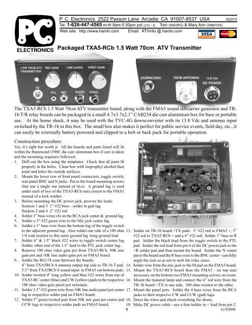
The <strong>TXA5</strong>-<strong>RCb</strong> <strong>1.5</strong> <strong>Watt</strong> <strong>70cm</strong> <strong>ATV</strong> transmitter board, along with the FMA5 sound subcarrier generator and TR-<br />
1b T/R relay boards can be packaged in a small 4.7x3.7x2.1” CAB234 die cast aluminium box for base or portable<br />
use. At the home shack, it may be used with the TVC-4G downconverter with its 13.8 Vdc and antenna input<br />
switched by the TR-1b in this box. The small box also makes it perfect for public service events, field day, etc., it<br />
can easily be externally battery powered and clipped to a belt or back pack for portable operation.<br />
Construction procedure:<br />
Yes, it’s tight but worth it. All the boards and parts listed will fit<br />
within the Hammond 1590C die cast aluminum box if care is taken<br />
and the mounting sequence followed.<br />
1. Drill out the box using the templates. Check that all parts fit<br />
properly in the holes. Clean box with isoprophyl alcohol then<br />
paint and letter the outside surfaces.<br />
2. Mount the lower row of front panel connectors, toggle switch,<br />
rear panel BNC and N jacks. Put in the board mounting screws<br />
(but use a single nut instead of two). A ground lug is used<br />
under each of two of the <strong>TXA5</strong>-<strong>RCb</strong> nuts closest to the FMA5<br />
instead of a lock washer.<br />
3. Before mounting the DC power jack, prewire the leads:<br />
Sockets 1 and 3 1” #22 buss - solder to gnd lug<br />
Sockets 2 and 4 2” #22 red<br />
4. Solder 1” buss wires (4) on the RCA jack center & ground lug.<br />
5. Solder a 3” #22 green wire to the Mic jack center lug<br />
6. Solder a 1” buss wire from the bottom lug of the toggle switch<br />
to the adjacent ground lug. Also solder one side of a 100 ohm 13. Solder on TR-1b board +TX pads: 3” #22 red to FMA5 +, 5”<br />
1/4 watt resistor to this same ground lug -long ground lead #22 red to <strong>TXA5</strong>-<strong>RCb</strong> + and a 4” #22 red. Solder 1” buss to R<br />
7. Solder 6” & <strong>1.5</strong>” black #22 wires to toggle switch center lug<br />
Solder, other end of the <strong>1.5</strong>” lead to the PTL jack center lug..<br />
pad. Solder the black lead from the toggle switch to the PTL<br />
pad. Solder the red lead from pin 4 of the DC power jack to the<br />
8. Remove 100 ohm video gain pot from <strong>TXA5</strong>-<strong>RCb</strong>, 50K mic<br />
gain pot and 10K line audio gain pot on FMA5 board.<br />
+R solder pad and then mount the board. Solder the N center<br />
pin to the board and the R buss wire to the BNC center - carefully<br />
9. Solder the RG174 coax between the boards:<br />
4” from <strong>TXA5</strong><strong>RCb</strong> A antenna output top side to TR-1b T pad.<br />
angle the iron so as not to melt the relay cases.<br />
14. Solder wire from the mic jack to the M pad on the FMA5 board.<br />
5.5” from <strong>TXA5</strong><strong>RCb</strong> S sound input to FMA5 out bottom pads. 15. Mount the <strong>TXA5</strong>-<strong>RCb</strong> board then the FMA5 - no top nuts<br />
10. Solder twisted 4” long yellow and blue #22 wires from top of necessary on the bottom two FMA5 mounting screws, no room.<br />
<strong>TXA5</strong>-RC center (blue) and CW (yellow) pads to the respective 16. Mount the transmit lamp and connect the 4” red wire from the<br />
100 ohm video gain panel pot terminals.<br />
TR-1b board +TX to one side, 100 ohm resistor to the other.<br />
11. Solder 3.5” #22 green wire from 10K line audio panel pot center 17. Mount the panel pots. Solder the 4 buss wires from the RCA<br />
lug to respective solder pad on FMA5 board.<br />
jacks to their respecive CW and CCW (gnd) lugs.<br />
12. Solder 3” green twisted pair from 50K mic gain pot center and 18. Dress the wires and check everything for shorts.<br />
CCW lugs to respective solder pads on FMA5 board. 19. Make DC power cable - use a fuse holder in + lead from pin 2.<br />
1<br />
(c) 5/2005
P. C. <strong>Electronics</strong> 2522 Paxson Lane Arcadia CA 91007-8537 USA ©2013<br />
Tel: 1-626-447-4565 m-th 8am-5:30pm pst (UTC - 8) Tom (W6ORG) & Mary Ann (WB6YSS)<br />
Web site: http://www.hamtv.com Email: <strong>ATV</strong>info @ hamtv.com<br />
Chassis Layout<br />
Cut out the drill templates here and on<br />
the next page, and place over the<br />
respective Hammond 1590C<br />
aluminum box sides. Align with the<br />
edges and hold in place with tape or a<br />
rubber cement. Center punch through<br />
the paper, or poke a hole through the<br />
paper, then place on the box and mark<br />
with a pencil. Measure the distances<br />
to the alignment reference holes and<br />
correct if necessary before drilling.<br />
Drill all holes with a .140 dia drill first,<br />
check alignment again, then finish with<br />
the larger drills. Debur all holes.<br />
Check all parts for fit, then clean the<br />
box with isopropyl alcohol prior to<br />
painting. Spray paint the outside<br />
surfaces of the box and cover. After<br />
drying, rub on letters can be applied<br />
and then a coat of clear paint. Again,<br />
after complete drying, assemble all the<br />
parts and wire per the sequential<br />
procedure on the previous page.<br />
<strong>Packaged</strong> <strong>TXA5</strong>-<strong>RCb</strong> <strong>1.5</strong> <strong>Watt</strong> <strong>70cm</strong> <strong>ATV</strong> <strong>Transmitter</strong> cont.<br />
Left<br />
.60<br />
.281 dia for<br />
transmit<br />
lamp<br />
.250 dia<br />
for<br />
transmit<br />
switch<br />
Front view from outside, top cover removed<br />
.312 dia for<br />
Mic gain pot<br />
.156 dia<br />
for<br />
PTL<br />
jack<br />
.312 dia for<br />
Line gain pot<br />
.234 dia<br />
for<br />
mic<br />
jack<br />
.250 dia<br />
for<br />
line audio<br />
jack<br />
Bottom view from outside<br />
Front<br />
Four .140 dia for <strong>TXA5</strong>-<strong>RCb</strong><br />
4-40x1/2 mounting screws<br />
Use a solder lug under<br />
these two nuts instead of a<br />
lock washer.<br />
.375 dia for<br />
Video gain pot<br />
.250 dia<br />
for<br />
video<br />
jack<br />
1.70<br />
Rear<br />
Rear view from outside, top cover removed<br />
.375 dia for<br />
BNC jack<br />
.625 dia for UG58 N<br />
antenna jack and four 4-<br />
40x1/2 mounting screws <strong>1.5</strong>0<br />
.625 dia for<br />
power jack<br />
2
P. C. <strong>Electronics</strong> 2522 Paxson Lane Arcadia CA 91007-8537 USA ©2013<br />
Tel: 1-626-447-4565 m-th 8am-5:30pm pst (UTC - 8) Tom (W6ORG) & Mary Ann (WB6YSS)<br />
Web site: http://www.hamtv.com<br />
Email: <strong>ATV</strong>info @ hamtv.com<br />
<strong>Packaged</strong> <strong>TXA5</strong>-<strong>RCb</strong> <strong>1.5</strong> <strong>Watt</strong> <strong>70cm</strong> <strong>ATV</strong> <strong>Transmitter</strong> cont.<br />
Parts list for packaging the <strong>ATV</strong> transmitter:<br />
RS part numbers = Radio shack, the alternates after are from<br />
Mouser - call: 1-800-346-6873<br />
Left Side view from outside, top cover removed<br />
.250<br />
1 <strong>TXA5</strong>-<strong>RCb</strong> <strong>ATV</strong> transmitter board, P. C. <strong>Electronics</strong><br />
1 FMA5 sound subcarrier board, P. C. <strong>Electronics</strong><br />
1 TR-1b T/R relay board, P. C. <strong>Electronics</strong><br />
1 UG-58 N chassis jack, P. C. <strong>Electronics</strong><br />
1 100 Ohm carbon pot, P. C. <strong>Electronics</strong><br />
1 Hammond 1590C die cast aluminum box, 546-1590C<br />
1 10K line audio pot, RS 271-1715, 31VA401<br />
1 50K mic gain pot, RS 271-1716, 31VA405<br />
1 UG1094 BNC chassis jack, RS 278-105<br />
1 4 pin chassis power jack, RS 274-002<br />
1 4 pin power plug, RS 274-001<br />
1 Inline fuse holder, RS 270-1217<br />
1 1 Amp 3AG fuse, RS 270-1005, 504-AGC-1<br />
2 RCA phone jack, 161-1052<br />
1 Mini mic jack, 16PJ012<br />
1 Sub-mini PTL jack, 16PJ100<br />
3 Knob, builders choice, ME 450-6015 - shown in pix<br />
1 Toggle switch, RS 275-612, ME 108-MS550K<br />
1 Lamp, RS 272-331<br />
1 100 Ohm 1/4 watt resistor, RS 271-1311, 29SJ250-100<br />
12 4-40x1/2” pan head screws, RS 64-3011, 5721-440-1/2<br />
22 4-40 nuts, RS 64-3018, 5721-440<br />
20 #4 internal tooth lock washers<br />
2 #4 solder lug, 534-7311<br />
4 Rubber bumpers, RS 64-2346, 517-SJ-5007BK<br />
Misc #22 hookup and buss wire, #18 for DC power leads<br />
Rear<br />
Board Mounting Detail<br />
Drill<br />
.140 dia<br />
hole<br />
4-40 Nut<br />
#4 Lock Washer<br />
<strong>PC</strong> Board<br />
4-40 Nut<br />
#4 Lock Washer<br />
Chassis<br />
4-40x1/2<br />
Screw<br />
Four .140 dia holes for<br />
FMA5 4-40x1/2<br />
mounting screws<br />
Chassis<br />
Four 4-40x.5"<br />
screws<br />
UG58<br />
N Conn.<br />
5/ 8" ho le<br />
Front<br />
Board<br />
TR-1b<br />
Eight 4-40<br />
nuts & lock<br />
washers<br />
Place screw through hole in chassis, drop on lock washer or solder<br />
lug, then finger tighten the nut. Then place the <strong>PC</strong> board on the nuts<br />
and check for fit. Push down on the board near the mounting hole<br />
while tightening with a screwdriver to lock in the alignment. Then<br />
put on the final lock washer and nut.<br />
5.5” RG174 coax<br />
O<br />
+<br />
FMA5<br />
Sound<br />
Subcarrier<br />
board<br />
1<br />
2<br />
3<br />
4<br />
+13.8 Vdc input,<br />
Ext line fused<br />
+13.8 Vdc to<br />
DC downconverter<br />
Power<br />
PTL<br />
+<br />
+TX<br />
+R<br />
TR-1b T/R<br />
relay board<br />
<strong>70cm</strong><br />
Antenna<br />
N jack<br />
R<br />
T<br />
BNC to<br />
Downconverter<br />
4” RG174 coax<br />
12V TX<br />
lamp<br />
10K Line<br />
Audio gain<br />
pot<br />
M<br />
50K Mic<br />
Audio gain pot<br />
100 Ohm<br />
1/4 watt<br />
TX<br />
RX<br />
Video Input<br />
+<br />
V<br />
cw<br />
<strong>TXA5</strong>-<strong>RCb</strong> <strong>ATV</strong><br />
<strong>Transmitter</strong> board<br />
w<br />
S<br />
A<br />
Line Audio<br />
Input<br />
Mic Input<br />
Push To Look<br />
3<br />
100 Ohm carbon<br />
video gain pot<br />
(c) 5/2005
1 <strong>Watt</strong> <strong>ATV</strong> <strong>Transmitter</strong> drill drawing using a Hammond 1590D die cast aluminum box.<br />
P.C. <strong>Electronics</strong> <strong>TXA5</strong>-<strong>RCb</strong>, FMA5-G and TR-1b boards. (c)2013<br />
Rear<br />
Bottom view is from the outside.<br />
Drill nine .140 dia holes<br />
4-40x5/16 screw<br />
Fuse Holder<br />
<strong>TXA5</strong>-<strong>RCb</strong> <strong>Transmitter</strong> board<br />
FMA5-G Sound board<br />
Cut out at outer edge of box lines. Place over and tape to the outside surfaces with the cover<br />
off. Center punch all holes. Pilot drill all holes with a .125 diameter drill. Check alignment<br />
then drill to final sizes. Debur by hand with a larger drill.<br />
Front<br />
Parts list is the same as with the smaller Hammond box on the previous page.<br />
.281 .281<br />
Power On & TX On<br />
12V lamps RS 272-331<br />
Top<br />
.328 LED .328 ..375<br />
50K Mic Gain<br />
.125<br />
10K Line<br />
Audio Gain<br />
100 Ohm<br />
Video Gain<br />
.250 .250<br />
On/Off switch T/R switch PTT<br />
submini jack<br />
.156 .234<br />
Mic<br />
mini jack<br />
.250 .250<br />
RCA jack<br />
Line Audio<br />
RCA jack<br />
Video In<br />
.250<br />
RCA video<br />
monitor jack<br />
UG58 type N<br />
Antenna jack<br />
Four .140 holes<br />
Top<br />
.250<br />
UG1094 BNC to<br />
downconverter<br />
jack<br />
.625<br />
DC power jack .625<br />
1. ground<br />
2. 13.8Vdc In<br />
3. ground<br />
4. + to downconverter


