

LOW COST GUNNPLEXER ATV - PC Electronics
LOW COST GUNNPLEXER ATV - PC Electronics
LOW COST GUNNPLEXER ATV - PC Electronics

Create successful ePaper yourself
Turn your PDF publications into a flip-book with our unique Google optimized e-Paper software.
P. C. <strong>Electronics</strong> 2522 Paxson Lane Arcadia CA 91007-8537 USA ©2013<br />
Tel: 1-626-447-4565 m-th 8am-5:30pm pst (UTC - 8) Tom (W6ORG) & Mary Ann (WB6YSS)<br />
Email: <strong>ATV</strong>info @ hamtv.com Web site: www.hamtv.com<br />
<strong>ATV</strong><br />
GET THE <strong>ATV</strong> BUG!<br />
<strong>LOW</strong> <strong>COST</strong> <strong>GUNNPLEXER</strong> <strong>ATV</strong><br />
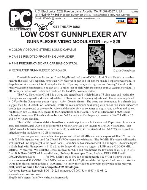
<strong>GUNNPLEXER</strong> VIDEO MODULATOR - ONLY $29<br />
❋ COLOR VIDEO AND STEREO SOUND CAPABLE<br />
❋ CAN BE REMOTED FROM THE <strong>GUNNPLEXER</strong><br />
❋ FINE FREQUENCY DC VARICAP BIAS CONTROL<br />
❋ REGULATED <strong>GUNNPLEXER</strong> DC POWER GVM-1 10 gHz Gunnplexer<br />
Dust off those Gunnplexers on 10 and 24 gHz and make an <strong>ATV</strong> link. Link Space Shuttle or weather<br />
radar to the local <strong>ATV</strong> repeater, remote an <strong>ATV</strong> receiver or pan and tilt camera on a hill top or repeater site, or<br />
do public service events - lots of uses plus the fun of putting the system together and “seeing” it work with<br />
readily available components. You can get 1-2 miles line of sight with the simple 10 mW Gunnplexers and 17<br />
dB horns, or farther with dishes and modified Ku band TV downconverters.<br />
The P. C. <strong>Electronics</strong> GVM-1 is a wired and tested board which drives a 75 ohm coax and load at the<br />
Gunnplexer varicap with video and adjustable DC bias for fine frequency adjustment. It also has a regulated<br />
+10 Vdc for the Gunnplexer power - up to 1A for 100 mW Gunns. The board can be mounted in a chassis (we<br />
suggest the LMB CAB247 or Hammond 1590D die cast aluminum box) along with one or two sound subcarrier<br />
boards (go stereo sound or use one for voice and the other for control tones or digital) and the bias and power<br />
run through two 75 ohm RG6 coaxes to the Gunnplexer on the tower. The P. C. <strong>Electronics</strong> FMA5 sound<br />
subcarrier boards are $39 each and can be specified for any specific frequency between 4.5 to 7.5 MHz - 6.2<br />
and 6.8 MHz are standard.<br />
The GVM-1 video modulator board has a deviation pot to enable the standard 1Vp-p video from cameras,<br />
camcorders, and VCR’s to be set for the 4 MHz NBFM <strong>ATV</strong> or 11MHz WBFM <strong>ATV</strong> standards. The<br />
FMA5 sound subcarrier boards also have variable deviation (50 kHz is standard for FM <strong>ATV</strong>) pot as well as<br />
injection to the modulator (-10 dB is standard).<br />
To receive you can use another Gunnplexer and off set 70 MHz and use a surplus satellite TV receiver<br />
with 70 MHz input as was used for C band TVRO systems for wideband. The 70 MHz IF systems will need a<br />
well shielded line amp to get to the noise floor - Radio Shack has some low cost in-line types. The noise figure<br />
is fairly high with Gunnplexers - 8-10 dB, so for longer distances we suggest a LNB into a 920-1600 MHz<br />
satellite TV receiver. We stock the Bensat receiver for $130 and recommend the low noise
P. C. <strong>Electronics</strong> 2522 Paxson Lane Arcadia CA 91007-8537 USA ©2013<br />
Tel: (626) 447-4565 m-th 8am-5:30pm pst (UTC - 8) Tom (W6ORG) & Mary Ann (WB6YSS)<br />
Email: <strong>ATV</strong>info @ hamtv.com Web site: www.hamtv.com<br />
GVM-1 Gunnplexer Video Modulator<br />
This board is designed to video modulate 5 to 100 mw Gunnplexers that have a separate varicap input. It will also supply the regulated<br />
+10 Vdc basic power up to 1 amp. Mount the board in an aluminum enclosure for both shielding and heat-sinking the regulator. The<br />
FMA5 sound subcarrier board can be mounted with the GVM-1 to add sound. The CAB247 makes a nice control box for the boards<br />
with panel room for mic and line audio gain pots, jacks, transmit switch, and the deviation and varicap bias pots - see layout page.<br />
The pots on the boards can be removed and wires run to the same value<br />
Video In<br />
panel type pots. For runs less than 6 inches, twisted wires can be run to the Sound<br />
boards but if longer, shielded cable is suggested. Use an F connector for Subcarrier<br />
the varicap output (VC). At the Gunnplexer end, remove any other inputs from<br />
components at the varicap input and connect the 75 ohm 1W terminating 1 or 2 FMA5<br />
resistor to that terminal and ground; run leads to another F chassis connector. set inj. pot<br />
Verify the 75 ohms with an ohm meter before applying voltage - any short for .5Vp-p<br />
S<br />
will blow the 2N2219A. The +10 Vdc can be another coax line with<br />
4.5 MHz<br />
connectors or a #18 red and black wire pair. Use a .1 and a 10 mF or larger NBFM,<br />
cap at the Gunnplexer to filter any + lead noise. If the suggested Gunnplexer<br />
S<br />
6.2 and<br />
*<br />
power is less than 10V drop the voltage at the Gunnplexer with series 6.8 MHz<br />
1N4001 diodes (.7V each).<br />
WBFM<br />
The board is designed for the standard video input of 1 volt peak to peak<br />
into 75 ohms and has a CCIR 405-1 pre-emphasis network. The 500 ohm Initially, set<br />
deviation pot can be set for either the 4 MHz or 11 MHz standards. 3 to bias for 4<br />
4Vdc varicap bias generally gives the best modulation linearity. Set the 4 Vdc, then<br />
BIAS<br />
V bias first, then adjust the Gunnplexer mechanical frequency after 2 minutes<br />
mechanical<br />
warm-up. The bias pot can then be used for fine frequency adjust-<br />
frequency<br />
ment (1 to 8.5 Vdc range- 5 to 8 MHz/V) until video limiting. SHF offers<br />
a heater kit for frequency stability in temperature varying environments.<br />
To receive, you can use another Gunnplexer and 70 MHz satellite TV receiver but a<br />
modified low noise Ku band or DSS LNB to a 950-1450 MHz satellite receiver TV<br />
works much better. There is almost a 10 dB difference in noise figure. You can get a<br />
modified LNB with a 9 gHz LO to tune the 10.0 to 10.5 gHz ham band for about $95<br />
delivered in the USA from Bob Platts G8OZP 43 Ironwalls Lane,Tutbury, England DE13<br />
9NH Email: bob_platts@hotmail.com Satellite TV receivers are advertised from $150<br />
up in various magazines. We stock the Bensat receiver - $130. 10.40 gHz video carrier<br />
with 6.8 MHz primary sound is standard in the USA for <strong>ATV</strong> and 6.2 for stereo or other<br />
function such as control, packet, ID, etc.<br />
10 and 24 GHz Gunnplexer sources:<br />
Advanced Receiver Research, POB 1242, Burlington, CT 06013 tel (860) 485-0310<br />
www.advancedreceiver.com<br />
10 GHz Web pages: http://www.tiac.net/users/wade<br />
Video<br />
input<br />
1V p-p<br />
20<br />
+12 to 14 Vdc<br />
7810<br />
16Vz<br />
+ reg +<br />
1N4745<br />
1 10<br />
.0033<br />
270<br />
75 75<br />
CCIR 405-1<br />
18uH<br />
premphasis<br />
network<br />
Sound #1<br />
Subcarrier<br />
input set for<br />
.5 v p-p =<br />
-10 dB video<br />
+<br />
82<br />
100<br />
1K<br />
5.6K<br />
270<br />
270<br />
#2<br />
Deviaton<br />
500<br />
5.5v<br />
2N2222<br />
+<br />
100<br />
.85v<br />
100<br />
5.6K<br />
2N2222<br />
1K<br />
100<br />
.1<br />
120<br />
1K<br />
RG-6<br />
75<br />
Ohm<br />
1W<br />
470<br />
270<br />
Varicap<br />
6.0v bias and 9.3v<br />
100<br />
Fine 2N2219<br />
+ Freq.<br />
5K<br />
adjust<br />
75 ohms<br />
at varicap<br />
.85v<br />
GVM-1 Gunnplexer Video Modulator<br />
P. C. <strong>Electronics</strong> (c) 2007<br />
1.4v<br />
>10 mF<br />
&.1 mF<br />
+<br />
Varicap<br />
Gunnplexer<br />
Gnd<br />
Board Mounting Detail<br />
Drill<br />
.140 dia<br />
hole<br />
4-40 Nut<br />
+12<br />
to 14<br />
Vdc<br />
Use a<br />
fuse<br />
*Set deviation for 1V p-p video out of a FM<br />
TV receiver.<br />
70 MHz satellite TV receivers require 20 dB<br />
more gain to reach the noise floor. Use 75<br />
Ohm TV inline amp or build MMIC amp and<br />
connect to Gunnplexer detector output..<br />
+10 Volts<br />
To Gunn<br />
diode<br />
1 to 8.5 Vdc<br />
output range -<br />
best linearity<br />
at 3 to 4 Vdc<br />
Mount in a shielded box.<br />
#4 Lock Washer<br />
<strong>PC</strong> Board<br />
Two 4-40 Nuts<br />
#4 Lock Washer<br />
Chassis<br />
4-40x1/2<br />
Screw<br />
rev 3/2007
P. C. <strong>Electronics</strong> 2522 Paxson Lane Arcadia CA 91007-8537 USA ©2013<br />
Tel: 1-626-447-4565 m-th 8am-5:30pm pst (UTC - 8) Tom (W6ORG) & Mary Ann (WB6YSS)<br />
Email: <strong>ATV</strong>info @ hamtv.com<br />
Web site: www.hamtv.com<br />
<strong>GUNNPLEXER</strong> CONTROL BOX<br />
The GVM-1 Gunnplexer modulator board needs to be put in a shielded box along with the 1 or 2 sound subcarrier<br />
boards. Some of the board trim pots can be replaced with panel equivalents and wires run to them from the boards. Shown is an example where the<br />
video gain/deviation, frequency/varicap bias, mike and line audio pots are placed on the front panel for easy operational adjustment. Below them are<br />
jacks for video, mike and line audio inputs. On the rear panel are two F61 F connectors for running the +10 Vdc Gunnplexer diode power and the<br />
varicap modulated bias. Mark the cables so that they do not get accidently switched.<br />
Purchase all the parts and the box before using the drill layout. The parts list and drill diameters are for the Radio Shack and Mouser part numbers<br />
but you may want to subsitute other parts and sources. It is easier if you interconnect and solder all the wires between the boards and the panel pots<br />
and jacks that mount from the inside before mounting in the box. Then mount the outside mounted jacks and attach their wires. Mount, wire and<br />
solder the fuse holder, 1N4744 15 Volt protection zener, power jack and on/off switch. Mount the boards and attach and solder the leads from the<br />
jacks, then mount the pots.<br />
Check for shorts with an ohmeter. On turn on, verify the +10 volts gunnplexer power and variable varicap bias on the F jacks. If you have an<br />
oscilloscope, turn on the sound subcarrier boards (10K line audio gain switch) one at a time and set the injection pot for 1/2 volt p-p at the bias<br />
output. Turn off sound subcarrier, plug in video and set deviation for 2 Vp-p to start and fine adjust for 1Vp-p out of a receiver. (c)3/2007<br />
Parts list<br />
Qty Description Source<br />
1 GVM-1 board P. C. <strong>Electronics</strong><br />
1 3AG fuse holder RS 270-739<br />
2 FMA5 board P. C. <strong>Electronics</strong><br />
1 1 Amp 3AG fuse RS 270-1005<br />
1 Hammond 1590D Box Mouser <strong>Electronics</strong><br />
1 1N4744 15V 1W zener RS 276-564<br />
1 4 pin power jack RS 274-002<br />
6 Knob builders choice<br />
1 4 pin power plug RS 274-001<br />
4 Rubber feet RS 64-2346 or 517-SJ5012<br />
2 F61 coax jack RS 278-212 or 16SF061<br />
1 4-40x5/16 pan head screw<br />
1 SPST Toggle switch RS 275-612 or ME108-MS550K 12 4-40x1/2 pan head screw<br />
2 Mini mic jack RS 274-292 or 16PJ012<br />
35 #4 nut<br />
3 RCA phono jack RS 274-346 or 161-1052<br />
22 #4 internal tooth lock washer<br />
1 500 ohm panel pot 31VA205<br />
2 #4 solder lug<br />
1 5K panel pot RS 271-1714 or 31VA305 62” #22 wire hookup wire<br />
2 10K panel pot w/switch RS 271-215 or 31XP401<br />
2 50K panel pot RS 271-1716 or 31VJ405<br />
RS=Radio Shack, Mouser 1-800-346-6873<br />
Wire list<br />
length From To<br />
1” Power jack pin 1 Ground lug under FMA5 #2 rear side mounting nut<br />
1.5” Power jack pin 2 Fuse holder<br />
1” On/off switch bottom lug Fuse holder - Zener to ground lug under FMA5 #2 front side mounting nut.<br />
4.5” On/off switch middle lug line audio #2 10K pot switch hot side lug<br />
4” line audio #2 10K pot switch hot side lug line audio #1 10K pot switch hot side lug<br />
1” Line audio #1 jack line audio #1 10K pot CW lug<br />
+13.8 1A<br />
1” line audio #1 jack ground lug line audio #1 10K pot CCW lug<br />
pin 2<br />
1” Line audio #2 jack line audio #2 10K pot CW lug<br />
pin 1<br />
15 Vz<br />
1” line audio #2 jack ground lug line audio #2 10K pot CCW lug<br />
1N4744<br />
GVM-1<br />
2” FMA5 #2 M pad Mic jack #2<br />
2” Twisted pair FMA5 #2 mic pot pads 50K mic #2 pot center and CCW lugs<br />
2” FMA5 #2 line audio center pot pad 10K line audio #2 center lug<br />
6” FMA5 #2 output pad GVM-1 S solder pad #2<br />
3.5” FMA5 #2 + input pad 10K line audio #2 switched side lug<br />
2” FMA5 #1 M pad Mic jack #1<br />
2” Twisted pair FMA5 #1 mic pot pads 50K mic #1 pot center and CCW lugs<br />
3” FMA5 #1 line audio center pot pad 10K line audio #1 center lug<br />
4” FMA5 #1 output pad GVM-1 S solder pad #1<br />
4” FMA5 #1 + input pad 10K line audio #1 switched side lug<br />
2” GVM-1 +10 pad +10V Gunnplexer power F jack<br />
2” GVM-1 VC pad Varicap bias F jack<br />
4” GVM-1 + input pad line audio #1 10K pot switch hot side lug<br />
2” GVM-1 V video in pad Camera video input jack<br />
8” 3 wires 500 ohm deviation pot GVM-1 500 ohm deviation pot pads<br />
3” 3 wires 5K video deviation pot GVM-1 5K deviation pot pads - put 22 ohm resistor in series with center lead.<br />
FMA5 #1<br />
FMA5 #2
Gunnplexer Control Box Layout and Drill Template (c) P. C. <strong>Electronics</strong> 2013<br />
Use Hammond 1590D die cast aluminum box. Cut out template on the inside edges of each panel. Align to the top edge<br />
on the front and rear outsides. Center the bottom template taking care to align with the noted front/rear sides. Center<br />
punch thru the template into the box. Drill all holes .140 and check for alignment, then drill the larger holes.<br />
open cover side<br />
.328 dia.<br />
5K fine freq<br />
control pot<br />
.328 dia.<br />
50K mic<br />
audio pot<br />
.328 dia.<br />
10K line<br />
audio pot<br />
.328 dia.<br />
50K mic<br />
audio pot<br />
.328 dia.<br />
10K line<br />
audio pot<br />
.328 dia.<br />
500 Ohm<br />
deviation pot<br />
.250 dia.<br />
Power on/off<br />
switch<br />
.234 dia.<br />
mic mini<br />
jack<br />
.250 dia.<br />
Line audio<br />
phono jack<br />
Front panel<br />
.234 dia.<br />
mic mini<br />
jack<br />
.250 dia.<br />
Line audio<br />
phono jack<br />
.250 dia.<br />
Video input<br />
phono jack<br />
bottom side<br />
Views are from outside<br />
Front side<br />
Bottom panel<br />
RS 270-739<br />
Fuse holder<br />
use 4-40x5/16<br />
screw<br />
FMA5 sound<br />
subcarrier #2<br />
6.2 MHz<br />
(optional)<br />
FMA5 sound<br />
subcarrier #1<br />
6.8 MHz<br />
GVM-1<br />
Gunplexer<br />
video modulator<br />
board<br />
7810<br />
Rear side<br />
All holes .140 dia for<br />
4-40 x 1/2 screws.<br />
open cover side<br />
.375 dia.<br />
Gunnplexer<br />
modulated<br />
bias F-61 jack<br />
.375 dia.<br />
Gunnplexer<br />
10 Vdc power<br />
F-61 jack<br />
Pin 1 Ground<br />
Pin 2 +13.8Vdc<br />
@1 amp<br />
.625 dia.<br />
13.8 Vdc<br />
RS274-002<br />
power input<br />
jack<br />
Color code or mark the two RG6 75 ohm coax cables so<br />
they do not get mixed up upon plugging in to the<br />
Gunnplexer and control box. Plug in Gunnplexer side first.<br />
bottom side
P. C. <strong>Electronics</strong> 2522 Paxson Lane Arcadia CA 91007-8537 USA ©2013<br />
Tel: 1-626-447-4565 m-th 8am-5:30pm pst (UTC - 8) Tom (W6ORG) & Mary Ann (WB6YSS)<br />
Email: <strong>ATV</strong>info @ hamtv.com Web site: www.hamtv.com<br />
<strong>GUNNPLEXER</strong> PACKAGING<br />
A big problem using a 10 to 24 gHz Gunnplexer for a fixed link or alternate <strong>ATV</strong> repeater transmitter, is how to weather proffit in some<br />
kind of enclosure that will keep the moisture out of the unit and horn antenna, and not attenutate the signal. While cruising a 99 cent<br />
stores plastic wares area I got the idea that the whole assembly can fit inside a plastic resealable and Microwave friendly food container.<br />
The aluminum mounting bracket shown is fine for <strong>ATV</strong> where an SHF propotional heater board is not necessary.<br />
If the plastic container can be used in a Microwave oven, it should be transparent<br />
to RF which I verified. These inexpensive containers are made to be air tight to<br />
keep food fresh in the refrigerator, so they should be fine on the tower. When you<br />
shop for yours, take the gunnplexer and horn wiht you to make sure they fit inside<br />
and the box says it is “microwaveable”. The 2 quart size is about right.<br />
The example shown here uses a Rubbermaid “Servin’ Saver” model 3911 1.9 qt.<br />
size which I paid $4 for, but there are plenty of less expensive ones at discount<br />
stores. The mounting brackets are made from 1.5” aluminum angle stock available<br />
at hardware stores and will fit any of the gunnplexer units, but check the rough fit<br />
before drilling any holes. The sketches shown are full sized and can be used<br />
directly to center punch mark the holes, but verify the dimensions before drilling.<br />
Mount the bracket to the<br />
gunnplexer and place inside<br />
the box. Mark the two 6-32<br />
screw mounting holes and<br />
two F jack drill locations with<br />
a felt marker through the<br />
bracket. Since the plastic is<br />
transparent, you can see<br />
where to drill the box through<br />
from the outside. Use a block<br />
of wood under the box to keep<br />
from cracking the plastic.<br />
The holes for the two F jacks<br />
are 5/8” dia and do not<br />
physically touch the jacks<br />
after mounting. Drill a .156<br />
drain and breathing hole<br />
anywhere on the bottom.<br />
Two F61 jacks are bolted on<br />
to the gunnplexer bracket for<br />
the modulated varicap bias<br />
and +10Vdc. Run jumper<br />
wires from the jacks to the<br />
Identify the two jacks with a felt marker on the<br />
outside bottom of the box in the same manner<br />
as the control box and RG6 cables.<br />
.625<br />
.25<br />
.75<br />
.50<br />
.875 1.25<br />
.156 dia holes for mounting<br />
to waveguide flange<br />
Gunnplexer mounting bracket<br />
Made from 1.5" aluminum angle stock<br />
.375 dia holes<br />
For F61 jacks<br />
.156 dia holes<br />
to mount to box<br />
3.00<br />
1.00<br />
.375<br />
1.00<br />
.375<br />
.375 3.125<br />
2.125<br />
Horn end<br />
.25<br />
.156 dia for 6-32 x .5 screw<br />
thru box and one end of<br />
gunnplexer bracket<br />
depending on box selected<br />
respective gunnplexer<br />
terminals and verify the .156 dia to mount to box<br />
This hole location may vary .156 dia<br />
operation before mounting in Box to mast clamp mounting bracket horizontally depending on actual<br />
the box. The gunnplexer<br />
Made from 1.5" aluminum angle stock<br />
horn length and box width. Verify<br />
bracket is held to the box with<br />
before drilling, mast should just clear<br />
two 6-32 x.5 pan head screws.<br />
mounts on the box outside bottom edge. the top edge of the box and cover.<br />
Use a flat #6 washer under the<br />
screw head on the outside to<br />
give more bearing surface on<br />
2.125 1.75<br />
6.00<br />
the plastic. Use a #6 lock<br />
washer under the nut.<br />
The mast clamp bracket is<br />
.250 dia holes<br />
also made from 1.5”<br />
for mast clamp<br />
aluminum angle and held to<br />
the box with 3 screws.<br />
Depending on placement in<br />
your box, one of the screws<br />
may also be one of the<br />
.75<br />
gunnplexer bracket screws. W6ORG 3/2007
P. C. <strong>Electronics</strong> 2522 Paxson Lane Arcadia CA 91007-8537 USA ©2013<br />
Tel: 1-626-447-4565 m-th 8am-5:30pm pst (UTC - 8) Tom (W6ORG) & Mary Ann (WB6YSS)<br />
Email: <strong>ATV</strong>info @ hamtv.com<br />
Web site: www.hamtv.com<br />
GVM-1 Board Applications<br />
This board has many other uses, with only slight modification, besides<br />
video modulating a Gunnplexer.<br />
FM <strong>ATV</strong> Receive Video Amp - Boost the low video output to 1V peak to<br />
peak from an analog satellite TV receiver by clipping out the input preemphasis<br />
20 Ohm resistor (marked with an X) and replacing the 270<br />
Ohm with a jumper on this board. Analog satellite TV runs 11 MHz<br />
deviation and <strong>ATV</strong> uses 4 MHz deviation on the 900 and 1200 MHz ham<br />
bands. So a gain of almost 3 is required to properly drive a video monitor<br />
for <strong>ATV</strong>. Some receivers have a video gain pot inside but still dont quite<br />
make it. This board has an adjustable gain of up to 5.<br />
FMA5<br />
inputs<br />
In<br />
*<br />
Video Amp<br />
Video Distribution Amp - You can drive a 2nd monitor, VCR, transmitter,<br />
etc., by tapping into a video line without loading it down with this board.<br />
Clip out the input pre-emphasis 20 Ohm resistor, * 82 Ohm input<br />
termination resistor, 270 Ohm resistor and add the jumper. In fact, you<br />
can add 2 or 3 modified GVM-1 boards in the DA configuration.<br />
75<br />
1 W<br />
Video<br />
Out<br />
+12<br />
to<br />
14V<br />
Add Sound Subcarrier - There are two inputs that can mix FM sound<br />
subcarriers to any video line going to an <strong>ATV</strong> transmitter that does not<br />
have sound. The FMA5-G sound subcarrier board(s) output can be<br />
connected to the solder pads on the GVM-1 board to be mixed in with the<br />
video.<br />
Pre-emphasis and De-emphasis - FM satellite receivers have deemphasis<br />
built in to the video output. However, most all FM video receivers<br />
made for wireless security camera systems do not. Pre-emphasis in the<br />
transmitter and corresponding de-emphasis in the receiver running 4 MHz<br />
deviation can gain twice the distance by lowering the noise floor. The<br />
stock GVM-1 can be used as is with the transmitter and another GVM-1<br />
with the 5 pre-emphasis parts replaced with the de-emphasis parts and<br />
one removed as shown at the top side of the board on the right.<br />
FMA5<br />
inputs<br />
In<br />
De-Emphasis<br />
When not used to also bias a Gunnplexer diode, the 5K varicap bias pot<br />
should first be set to give 2.0 Vdc at the VC video output when connected<br />
to a 75 Ohm resistive load. Also, to limit the current if accidently grounded,<br />
the 75 Ohm 1 Watt resistor is run from the VC solder pad to the video out<br />
jack or video out cable. The 5K Deviation pot becomes the video gain<br />
pot for setting the output to 1 Vp-p into the resistive 75 Ohm termination<br />
in your monitor, VCR or transmitter.<br />
75<br />
1 W<br />
Video<br />
Out<br />
+12<br />
to<br />
14V<br />
The GVM-1 board is available from P. C. <strong>Electronics</strong> for $29 each or $25 each in quantity.<br />
W6ORG©3/2007


