Create successful ePaper yourself
Turn your PDF publications into a flip-book with our unique Google optimized e-Paper software.
Ele<strong>ct</strong>ricity Meters IEC<br />
INDUSTRIAL+COMMERCIAL<br />
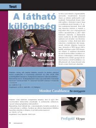
Landis+Gyr Dialog<br />
ZMD400AT/CT - ZFD400AT/CT<br />
TECHNICAL DATA<br />
Current<br />
Nominal Current In<br />
1 A, 2 A, 5 A, 5||1 A<br />
Maximal Current Imax<br />
metrological 1 A, 2 A, 5A<br />
metrological 5||1 A<br />
thermal 1 A<br />
thermal 2 A, 5A, 5||1 A<br />
200 % In<br />
6 A<br />
2.4 A<br />
12 A<br />
Short Circuit Current<br />
0.5 s with 20 x Imax<br />
Mesurement Accuracy<br />
Accuracy ZxD405xT<br />
a<strong>ct</strong>ive energy to IEC 62053-22 class 0.5 S<br />
rea<strong>ct</strong>ive energy to IEC 62053-23 class 1<br />
Accuracy ZxD410xT<br />
a<strong>ct</strong>ive energy to IEC 62053-21 class 1<br />
rea<strong>ct</strong>ive energy to IEC 62053-23 class 1<br />
Measurement Behaviour<br />
Voltage<br />
Nominal Voltage Un ZMD400xT<br />
3 x 58/100…69/120 V<br />
3 x 110/190…133/230 V<br />
3 x 220/380…240/415 V<br />
wide voltage range 3 x 58/100…240/415 V<br />
Nominal Voltage Un ZFD400xT<br />
wide voltage range<br />
3 x 100…120 V<br />
3 x 220…240 V<br />
3 x 100…415 V<br />
Starting Current ZxD405xT<br />
according to IEC<br />
0.1 % In<br />
typical<br />
0.07 % In<br />
5||1 A as 1 A meter<br />
Starting Current ZxD410xT<br />
according to IEC<br />
0.2 % In<br />
typical<br />
0.14 % In<br />
5||1 A as 1 A meter<br />
The startup of the meter is controlled by the<br />
starting power and not by the starting current.<br />
Starting Power in M-Circuit<br />
nominal power x starting current<br />
single phase<br />
Voltage Range<br />
80 % – 115 % Un<br />
Frequency<br />
Nominal Frequency fn<br />
50 or 60 Hz<br />
tolerance ± 2 %<br />
Starting Power in F-Circuit<br />
all phases<br />
nominal voltage / √3 x starting current x 3<br />
H 71 0200 0062 k en - ZMD400AT/CT - ZFD400AT/CT - Technical Data<br />
Landis+Gyr<br />
1 / 4
Operating Behaviour<br />
Voltage Interruption (Power Down)<br />
bridging time according to IEC<br />
0.5 s<br />
<strong>data</strong> storage<br />
after another 0.2 s<br />
switch off<br />
after approx. 2.5 s<br />
Voltage Restoration (Power Up)<br />
fun<strong>ct</strong>ion standby 3 phases<br />
fun<strong>ct</strong>ion standby 1 phase<br />
dete<strong>ct</strong>ion of<br />
energy dire<strong>ct</strong>ion + phase voltage<br />
after 2 s<br />
after 5 s<br />
after 2 to 3 s<br />
Power Consumption<br />
Power Consumption per Phase in the Voltage Circuit<br />
phase voltage 58 V 110 V 240 V<br />
a<strong>ct</strong>ive power (typical) 0.65 W 0.7 W 0.8 W<br />
apparent power (typical) 1.3 VA 1.7 VA 3.6 VA<br />
Power Consumption per Phase in the Current Circuit<br />
phase current 1 A 5 A 10 A<br />
a<strong>ct</strong>ive power (typical) 5 mW 0.125 W 0.5 W<br />
apparent power (typical) 5 mVA 0.125 VA 0.5 VA<br />
Environmental Influences<br />
Temperatur Range to IEC 62052-11<br />
operation -25 °C – +70 °C<br />
storage -40 °C – +85 °C<br />
Temperature Coefficent<br />
range von -25 °C – +70 °C<br />
average value (typical)<br />
± 0.012 % per K<br />
at cosϕ=1 (from 0.05 Ib to Imax) ± 0.02 % per K<br />
at cosϕ=0.5 (from 0.1 Ib to Imax) ± 0.03 % per K<br />
Impermeability according to IEC 60529<br />
IP51<br />
Ele<strong>ct</strong>romagnetic Compatibility<br />
Ele<strong>ct</strong>rostatic Discharges to IEC 61000-4-2<br />
conta<strong>ct</strong> discharge<br />
15 kV<br />
Ele<strong>ct</strong>romagnetic RF Fields to IEC 61000-4-3<br />
80 MHz – 2 GHz 10 and 30 V/m<br />
Radio Interference Suppression<br />
according to IEC/CISPR 22<br />
class B<br />
Fast Transient Burst Test to IEC 61000-4-4<br />
current and voltage circuits not under load 4 kV<br />
current and voltage circuits under load<br />
according to IEC 62053-21/22/23<br />
2 kV<br />
auxiliary circuits > 40 V<br />
1 kV<br />
Fast Transient Surge Test to IEC 61000-4-5<br />
current and voltage circuits<br />
4 kV<br />
auxiliary circuits > 40 V<br />
1 kV<br />
Insulation Strenght<br />
Insulation Strenght 4 kV @ 50 Hz during 1 min<br />
Impulse Voltage 1.2/50µs to IEC 62053-11<br />
current and voltage circuits<br />
8 kV<br />
auxiliary circuits<br />
6 kV<br />
Prote<strong>ct</strong>ion Class according to IEC 60050-131 2<br />
Calendar Clock<br />
Accuracy<br />
Backup Time (Power Reserve)<br />
with supercap<br />
loading time for max backup time<br />
with battery (optional)<br />
battery type<br />
< 5 ppm<br />
> 20 days<br />
300 h<br />
10 years<br />
CR-P2<br />
Display<br />
Chara<strong>ct</strong>eristics<br />
type<br />
LCD liquid crystal display<br />
digit size in value field<br />
8 mm<br />
number of positions in value field up to 8<br />
digit size in index field<br />
6 mm<br />
number of positions in index field up to 8<br />
Inputs and Outputs<br />
Control Inputs<br />
control voltage Us<br />
100…240 V AC<br />
input current<br />
< 2 mA ohmic at 230 V AC<br />
Output Conta<strong>ct</strong>s<br />
type<br />
voltage<br />
max current<br />
max switching frequency<br />
solid state relay<br />
12…240 V AC/DC<br />
100 mA<br />
50 Hz<br />
Optical Test Output A<strong>ct</strong>ive and Rea<strong>ct</strong>ive Energy<br />
type<br />
red LED<br />
number 2<br />
meter constant<br />
sele<strong>ct</strong>able<br />
Communication Interfaces<br />
Optical Interface according to IEC 62056-21<br />
type<br />
serial, bidire<strong>ct</strong>ional, half duplex<br />
max bit rate<br />
9600 bps<br />
protocols<br />
IEC 62056-21 and dlms<br />
Landis+Gyr<br />
2 / 4<br />
H 71 0200 0062 k en - ZMD400AT/CT - ZFD400AT/CT - Technical Data
Communication Units<br />
Exchangeable communciation units for various<br />
applications.<br />
Additional Power Supply (optional)<br />
on extension board 025x<br />
nominal voltage range<br />
tolerance<br />
frequency<br />
max power consumption<br />
100…160 V DC<br />
100…240 V AC<br />
80 – 115 % Un<br />
50 or 60 Hz<br />
2.2 W<br />
Ripple Control Receiver (optional)<br />
on extension board 043x or 003x (ZMD400 only)<br />
nominal voltage<br />
58 or 230 V<br />
frequency<br />
50 or 60 Hz<br />
fun<strong>ct</strong>ional voltage Uf<br />
0.3 – 2.5 % Un<br />
control frequency fs<br />
110 – 2000 Hz<br />
bandwidth<br />
0.6 – 6 % fs<br />
Other Conne<strong>ct</strong>ions<br />
type<br />
screwless spring-type terminal<br />
max current of voltage outputs<br />
1 A<br />
max voltage of inputs<br />
250 V<br />
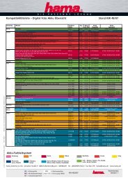
Meter Dimensions (Standard Terminal Cover)<br />
6.2 75<br />
190<br />
206<br />
26<br />
40<br />
281.5<br />
Weight and Dimensions<br />
Weight<br />
approx. 1.5 kg<br />
150<br />
177<br />
75<br />
External Dimensions<br />
width<br />
height (with short terminal cover)<br />
height (with standard terminal cover)<br />
depth<br />
Suspension Triangle<br />
height (suspension eyelet open)<br />
height (suspension eyelet covered)<br />
widht<br />
177 mm<br />
244 mm<br />
281.5 mm<br />
75 mm<br />
206 mm<br />
190 mm<br />
150 mm<br />
Terminal Layout<br />
Inputs and/or<br />
output conta<strong>ct</strong>s of<br />
extension board<br />
U1<br />
U2 U3<br />
U1 U2 U3 N<br />
I1 I1 I2 I2 I3 I3<br />
Communication conne<strong>ct</strong>ions<br />
according to documentation CU-xx<br />
N<br />
Voltage conne<strong>ct</strong>ions<br />
Current conne<strong>ct</strong>ions<br />
Control inputs and<br />
output conta<strong>ct</strong>s<br />
Voltage outputs<br />
Terminal Cover<br />
short<br />
standard<br />
long<br />
GSM<br />
ZxB-type 80 mm<br />
ZxB-type 110 mm<br />
Metcom3 adapter<br />
FTT4/5 adapter<br />
no free space<br />
40 mm free space<br />
60 mm free space<br />
60 mm free space<br />
80 mm free space<br />
110 mm free space<br />
Conne<strong>ct</strong>ions<br />
Phase Conne<strong>ct</strong>ions<br />
type<br />
screw type terminals<br />
diameter<br />
5.2 mm<br />
recommended condu<strong>ct</strong>or cross se<strong>ct</strong>ion 4 – 6 mm 2<br />
screw head Pozidrive Kombi No. 1<br />
screw dimensions M4 x 8<br />
screw head diameter<br />
≤ 5.8 mm<br />
tightening torque<br />
< 1.7 Nm<br />
H 71 0200 0062 k en - ZMD400AT/CT - ZFD400AT/CT - Technical Data<br />
Terminal Dimensions<br />
16 10 10 10 10 10 10 10 10 10<br />
150<br />
168<br />
Material<br />
Housing<br />
The meter housing is made of polycarbonate which<br />
is partly glass-fibre reinforced.<br />
5.2<br />
12.5<br />
Landis+Gyr<br />
3 / 4
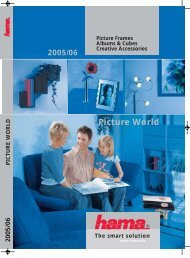
Type Designation<br />
ZMD 4 10 C R 44 4207 . c1<br />
Network Type<br />
ZFD<br />
ZMD<br />
Accuracy Class<br />
3-phase 3 wire network (F-circuit)<br />
3-phase 4 wire network (M-circuit)<br />
Conne<strong>ct</strong>ion Type<br />
3: Dire<strong>ct</strong> conne<strong>ct</strong>ion<br />
4: Transformer operated<br />
10: A<strong>ct</strong>ive energy class 1 according to IEC<br />
05: A<strong>ct</strong>ive energy class 0.5 S according to IEC<br />
Measured Quantities<br />
C: A<strong>ct</strong>ive and rea<strong>ct</strong>ive energy<br />
A: A<strong>ct</strong>ive energy<br />
Constru<strong>ct</strong>ion<br />
R: With integrated interface<br />
T: With exchangeable communication units<br />
Tariffication<br />
21: Energy rates, external rate control via control inputs<br />
24: Energy rates, internal rate control via time switch<br />
(additionally possible via control inputs)<br />
41: Energy and demand rates, external rate control via control inputs<br />
44: Energy and demand rates, internal rate control via time switch<br />
(additionally possible via control inputs)<br />
Additional Fun<strong>ct</strong>ions<br />
All versions with 3 control inputs and 2 output conta<strong>ct</strong>s<br />
0000: no additional fun<strong>ct</strong>ions 0007: + load profile<br />
0600: 6 outputs 0607: + load profile<br />
2400: 2 control inputs, 4 outputs 2407: + load profile<br />
4200: 4 control inputs, 2 outputs 4207: + load profile<br />
0030: integrated ripple control receiver 0037: + load profile<br />
0430: 4 outputs, integrated ripple control receiver 0437: + load profile<br />
0250: 2 outputs, additional power supply 0257: + load profile<br />
Integrated Interface (R-Types only)<br />
c1: RS232 interface<br />
c2: RS485 interface<br />
c3: CS interface<br />
Landis+Gyr Ltd.<br />
Feldstrasse 1<br />
CH – 6301 Zug<br />
Switzerland<br />
Phone: +41 41 724 41 41<br />
www.landisgyr.com<br />
Landis+Gyr<br />
4 / 4<br />
H 71 0200 0062 k en - ZMD400AT/CT - ZFD400AT/CT - Technical Data