SuperFill™ Surge Reduction Equipment - Halliburton
SuperFill™ Surge Reduction Equipment - Halliburton
SuperFill™ Surge Reduction Equipment - Halliburton

Create successful ePaper yourself
Turn your PDF publications into a flip-book with our unique Google optimized e-Paper software.
11-1 Casing Attachments
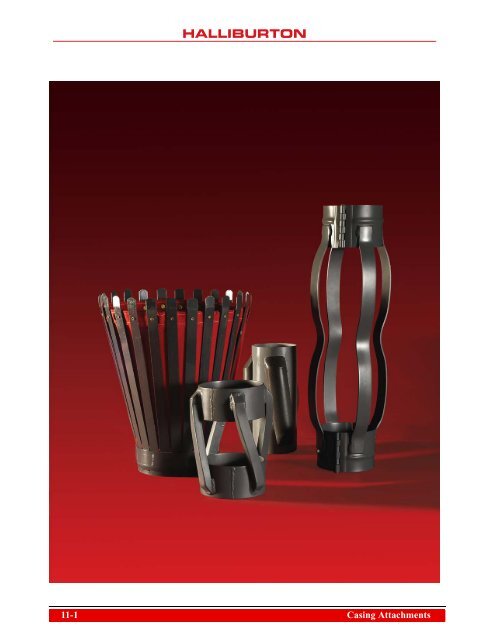
Casing Attachments<br />
Casing attachments are items attached to the casing OD as<br />
the casing is run in the wellbore. These items are designed to<br />
contribute to a successful primary cementing job. Over time,<br />
numerous casing attachments have been developed for use in<br />
primary cementing operations. These attachments can help<br />
the operator successfully place the casing string in the well<br />
and enhance mud removal from the wellbore. The type of<br />
primary cementing equipment used depends on individual<br />
well requirements and can vary widely within geographical<br />
areas and from field to field. Secondary cementing has<br />
become very expensive and casing attachments can provide<br />
inexpensive insurance for a perfect bond. The primary<br />
cementing equipment should be closely monitored to achieve<br />
a good primary cement job and eliminate the need for a<br />
secondary cementing operation. Effective proper placement<br />
is as important as the correct product selection. The main<br />
objective for using this equipment is:<br />
• A need to get tubulars to target depth (TD) of a<br />
well design.<br />
• Help achieve optimum circulation and zonal isolation.<br />
• Help reduce chances of differential sticking.<br />
<strong>Halliburton</strong> has supplier agreements with several top rated<br />
casing attachment manufacturers. To offer customers a wide<br />
selection of centralizer options and designs, <strong>Halliburton</strong> is<br />
also a distributor and supplier of the following<br />
manufacturer's product lines:<br />
• Centek<br />
• Antelope<br />
• Casewell<br />
• Ray Oil Tool<br />
• Downhole Products<br />
Products offered through <strong>Halliburton</strong> from these<br />
manufacturers provide options for all types of well designs<br />
from shallow land wells to the deepest offshore extendedreach<br />
horizontal wells. Size combinations are available on<br />
request and custom built; special-order items can be quoted<br />
as needed. Contact a local <strong>Halliburton</strong> sales representative<br />
for additional information.<br />
Casing Attachments<br />
This section contains information about the following casing<br />
attachments:<br />
• Centralizers:<br />
– Provide uniform annular clearance and reduce drag<br />
when running casing.<br />
• Stop collars:<br />
– Secures placement and limits travel on attachments to<br />
casing string.<br />
• Scratchers and wipers:<br />
– Remove mudcake on the wellbore.<br />
• Cement baskets:<br />
– Helps support cement in the annulus.<br />
© 2013 <strong>Halliburton</strong>. All Rights Reserved.<br />
Casing Attachments 11-2
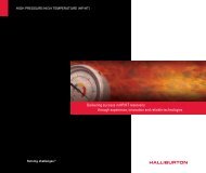
<strong>Halliburton</strong> Protech CRB ® and Protech DRB ® Composite Systems<br />
<strong>Halliburton</strong> Protech CRB® and Protech DRB® composite<br />
systems consisting of a ceramic composite compound and a<br />
unique bonding process, licensed to <strong>Halliburton</strong> from Eni<br />
S.p.A.*, is a new innovative technology that can help<br />
significantly enhance well design versatility while<br />
potentially decreasing associated risks and overall project<br />
cost. <strong>Halliburton</strong> Protech products are currently provided<br />
through three facilities located in Ravenna, Italy; Aberdeen,<br />
Scotland; and Houston, Texas.<br />
<strong>Halliburton</strong> Protech CRB (Casing Resin Blend) and<br />
Protech DRB (Drillpipe Resin Blend) materials can be used<br />
for many applications:<br />
• Casing centralization including slim hole and deviated<br />
wellbore applications.<br />
• Drillpipe wear protection<br />
• Stop collars<br />
• Wear bands<br />
• Deflection wedges<br />
• Cutting bed cleaners<br />
• Screen protection devices<br />
• General friction reduction applications<br />
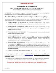
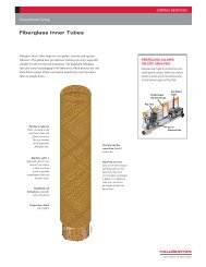
<strong>Halliburton</strong> Protech CRB ® Centralizers<br />
The <strong>Halliburton</strong><br />
Protech CRB<br />
centralizer is solidtype<br />
centralizer<br />
mechanically<br />
formed and<br />
chemically bonded<br />
directly to the<br />
customer’s tubular<br />
Protech CRB® Centralizer<br />
pipe surface. The<br />
proprietary bonding process uses a composite resin<br />
composite material. The customer has the option to choose<br />
any size, shape, or location of the composite blades or<br />
products to their casing or drillpipe.<br />
HAL24955<br />
*Eni S.p.A. (“Eni”) is the owner of Patent Applications and Patents<br />
regarding the technologies of the process of centralization of CTG<br />
utilizing composite ceramic centralizers. <strong>Halliburton</strong> is the exclusive<br />
licensee world wide regarding the technologies of the<br />
aforementioned process.<br />
Features<br />
• Non-API rated<br />
• Ceramic composite material molded onto<br />
customer's casing.<br />
• Designed to fit specific well applications.<br />
• Can be installed on any grade of pipe, including<br />
CRA alloys.<br />
• Unique bonding process helps ensure a strong mechanical<br />
bond.<br />
• Provides centralization option for close tolerance<br />
wellbores.<br />
• Provides smooth, uninterrupted flow during circulation<br />
attributed to the absence of any banded product placed<br />
around the casing.<br />
• Composite material exhibits extreme abrasion and impact<br />
resistance.<br />
• Ideal for deviated sections of borehole as material<br />
provides a low coefficient of friction.<br />
• Field proven technology.<br />
• Material is CO 2 and H 2 S resistant.<br />
• A high thermal degradation temperature and excellent<br />
impact resistance at -25°F.<br />
• Composite centralizers successfully used in both<br />
conventional and slim profile wells.<br />
• Helps enable homogeneous cement slurry distribution.<br />
• Product applications are usually performed in a pipe yard<br />
where customer's pipe is stored. Field location<br />
installations are available.<br />
Process<br />
Protech CRB and Protech DRB centralizers are<br />
recommended to be applied in one of <strong>Halliburton</strong>’s<br />
environmentally controlled mass installation facilities, but<br />
can also be installed in customer's pipe yard, or on location<br />
if prearranged.<br />
11-3 Casing Attachments
Step 1—to prepare the pipe, special high-tech sand-blasting<br />
techniques are performed to the blade area.<br />
Step 6—the blade material is prepared using a precision<br />
blending and mixing unit.<br />
Step 2—sandblasting is performed to achieve a near-white<br />
metal finish to ensure a rough profile to allow the carbon<br />
fiber ceramic blend to bond to the micro peaks and valleys in<br />
the pipe's surface.<br />
Step 7—the blade material is injected into molds using a<br />
controlled process for a solid fill of the blade mold cavity.<br />
Step 3—the roughness is checked with pressure applied<br />
roughness test strips.<br />
Step 8—after installation, the blades are allowed to cure and<br />
final inspection for material quality control is performed.<br />
Step 4—the test paper is then measured for proper pipe and/<br />
or profile and is correct per specification.<br />
Step 9—final check of OD measurements are performed<br />
before being ready for shipment.<br />
Step 5—injection molds are produced according to the<br />
computer-designed centralizer profile and installed with<br />
special double-sided, pressure-sensitive tape during<br />
application.<br />
Step 10—the final process of protective packaging devices are<br />
installed to prepare pipe for delivery to customers.<br />
Casing Attachments 11-4
Centek Centralizers<br />
Centralizers are manufactured in the UK (England) and in<br />
the USA (Oklahoma) by Centek Ltd and Centek Inc.,<br />
respectively. <strong>Halliburton</strong>, as a non-exclusive distributor by<br />
agreement, yet holds exclusivity in numerous regions, sells,<br />
and markets, as is required. This integral one-piece bow<br />
spring centralizer is a high-end centralization product. The<br />
centralizers are built to gauge to offer easier, RIH,<br />
maximize standoff, and maximize the cement job. The<br />
UROS range of centralizers are built mostly for passing<br />
through close tolerance situations and then opening back<br />
up into under reamed holed sections, or washed out<br />
sections, while still providing quality stand-off<br />
performance. Bow spring sections are based on a straight<br />
bladed principle, but are curved in both axial and<br />
tangential directions. This cross curvature conforms to the<br />
borehole wall, while the axial curvature changes<br />
proportionally as it encounters different loads. As the loads<br />
increase, the surface contact area also increases, reducing<br />
the load per square unit of area. This helps avoid<br />
compression and shear failure of the formation surface.<br />
Centek S2 Slip-on Centralizer<br />
Features<br />
• Rating—API Specification 10D and NQA 9001-2008.<br />
• Design features<br />
– Smooth bow profile overall<br />
– Non-welded<br />
– Made to gauge<br />
– Integral bow design for increased strength and<br />
performance.<br />
– Zero weak points, such as hinges, welds, or<br />
mechanical interlocks.<br />
– Flexible to absorb both axial and radial loading.<br />
– Powder coated red finish<br />
• Performance<br />
– Zero start and running force with exceptional<br />
restoring force.<br />
– Improved flow by area and improved pipe rotation.<br />
– Low torque and low drag units.<br />
– Improved zonal isolation<br />
• Applications<br />
– Used in most well applications and geometries for<br />
vertical, horizontal ERD, close tolerance, or under<br />
reamed well conditions.<br />
– The UROS units are recommended where tight<br />
restrictions through previous set casing are<br />
encountered; also recommended when increased<br />
structural integrity is required.<br />
– Specialized in centralization for under reamed hole<br />
sections.<br />
• Recommended to be run between limit clamps<br />
• Sizes available—2 7/8 to 20 in.; custom sizes available.<br />
• Minimum hole size—2 7/8 in. (4 in.) hole.<br />
• Maximum hole size—20 in. (26 in.) hole.<br />
Centek Model S2<br />
Centralizer<br />
HAL24954<br />
Centek S2 Centralizers<br />
Installed between Two Centek<br />
Limit Clamps<br />
11-5 Casing Attachments
Centek UROS (Under Reamed Offset Bows) Centralizer<br />
The Centek UROS centralizer is designed for drag reduction<br />
on initial insertion and reduced accumulative loads on<br />
restarting and running forces during running in hole (RIH).<br />
The unit is designed primarily for under reamed wells. This<br />
design is also suitable for washed out sections where good<br />
centralization is still a critical requirement. The UROS<br />
centralizer shows significant reduction on initial insertion<br />
forces as well as reduced running forces through the previous<br />
set casing. Once through this compressed stage, the unit will<br />
revert to gauge, maximizing standoff with zero drag.<br />
• Casing sizes available—7 to 16 in.<br />
• Minimum hole size—9 1/2 to 20 in.<br />
Features<br />
• Rating—There is no current API standard for any under<br />
reamed application; however, testing of such units are to<br />
API Specification 10D and NQA 9001-2008.<br />
• Description—typical design is of a slip-on, semi-rigid, 6-<br />
bow centralizer, with two offset placements of three<br />
alternating opposite end offset bows, whereas only three<br />
larger nominal OD end bows enter the restriction at one<br />
time. Then, as the centralizer continues to enter into the<br />
restriction at midpoint, the other three opposing offset<br />
bows now enter the restriction.<br />
• Performance—smooth bow profile overall, non-weld<br />
integral bow design for increased strength and<br />
performance. A robust, ultra-high-strength, one-piece<br />
construction centralizer with no weak points, such as<br />
hinges or mechanical interlocks. Flexible to absorb both<br />
axial and radial loading.<br />
– Designed to easily pass through previously set casings.<br />
– Engineered for tight clearance/close tolerance<br />
applications.<br />
– Ideal for under reamed holes sections.<br />
– Offers lower starting forces when entering restrictions.<br />
– Gives adequate restoring force to support the casing.<br />
– Helps with well cleanout and circulation.<br />
– Reduces risk of differential sticking.<br />
Centek UROS Centralizer<br />
Casing Attachments 11-6
Centek Stop Collars<br />
A key element of the Centek stop collar is its high axial load<br />
capability. All Centek stop collars are heat treated to<br />
improve tensile strength, especially in the critical internal<br />
thread area. This is combined with high tensile set screws<br />
of a specific thread pitch to match the low profile<br />
characteristics of the product. Thus, when tightened to 35<br />
lb/ft, the Centek stop collars provide a vastly superior axial<br />
holding force when compared to other stop collars. With<br />
these properties and the correct make-up, the stripping of<br />
threads has been eliminated.<br />
Centek stop collar<br />
Applications<br />
• Used in all types of well designs.<br />
• Sizes available—2 7/8 to 20 in. (custom sizes available).<br />
Benefits<br />
• High axial load capability<br />
• Special use high-tensile holding force set screws.<br />
• Large contact surface area<br />
• Heat treated, eliminates internal thread stripping.<br />
Options<br />
• Available with stainless steel set screws.<br />
• Available in heavy-duty style with extended length and<br />
two rows of set screws.<br />
Centek heavy-duty stop collar<br />
(Top) Centek Stop Collar; (Bottom) Centek Heavy-duty Stop Collar<br />
Features<br />
• Rating—tested in accordance to API<br />
recommendations.<br />
• Design appearance—one-piece slip-on type with set<br />
screws. Non-welded design. Manufactured from highgrade,<br />
heat-treated steel. Centek stop collars have a<br />
high quality powder coated finish.<br />
• Performance—offers extremely high holding<br />
performance to Centek Centralizers.<br />
11-7 Casing Attachments
Antelope Oil Tools<br />
Antelope, with headquarters in Mineral Wells, Texas,<br />
currently manufactures more than 800 different material<br />
numbers, including products that are available to meet API<br />
Specification 10D. Antelope holds certification in ISO<br />
9001:2008 for quality management in the design and<br />
manufacture of casing centralizers and related accessories for<br />
the energy industry. Antelope is licensed by the American<br />
Petroleum Institute and has a “certificate of authority to use<br />
the official API monogram” on their API-certified products.<br />
Antelope Oil Tools Production Facility<br />
Antelope Oil Tools Production Center Aisle<br />
© 2013 Antelope. Photographs are the property of Antelope Oil Tools and<br />
used with permission by <strong>Halliburton</strong>.<br />
Bow Type Centralizer Classifications and<br />
Embodiments<br />
• API centralizers:<br />
– Meet or exceed API Specification 10D.<br />
– Are tested and monogrammed.<br />
– Meet starting-running-restoring force criteria as per<br />
API requirements.<br />
– Offer optimum performance.<br />
• Non-API centralizers:<br />
– Developed for customer preference and economics<br />
(less expensive).<br />
– Used when API specs are not required (not as rigid<br />
as API).<br />
– When hole conditions do not allow API specification<br />
centralizers to be run because of non-flexibility issues.<br />
– Wider range of size combinations.<br />
– Built to aid within tight restrictions of a casing string<br />
design.<br />
– Manufactured with the same structural materials and<br />
machinery as API centralizers.<br />
– Testing records are not required to be maintained.<br />
• Hinged centralizers:<br />
– Allow for easy installation around casing coupling or<br />
stop collar.<br />
– More adaptable to casing strings with upsets.<br />
– Have a rugged interlocking collar design.<br />
– Can take up less space on location or the rig floor.<br />
• Non-hinged centralizers (slip on):<br />
– Are stronger and have enhanced mechanical integrity.<br />
– Used in close tolerance applications.<br />
– Cannot be run over casing collars or pipe upsets—must<br />
use limit clamps or set screws.<br />
– Better suited for pipe rotation.<br />
– Shipping cost are higher because of nesting package<br />
limitations.<br />
• Set screws:<br />
– Used for securing and limiting travel of centralizers and<br />
attachments to casing.<br />
– Used when centralizers cannot be installed around a<br />
casing collar.<br />
Casing Attachments 11-8
– Used when casing is flush joint or non-collared.<br />
– Can be installed on most centralizers as an option.<br />
– Should only be installed on leading collar (bottom) of<br />
centralizer.<br />
– Centralizers with set screws limit the ability of the<br />
centralizer to be “pulled” in both directions.<br />
– Eliminate the use of limit clamps.<br />
• Turbo fins:<br />
– Help create added turbulence in an annulus section.<br />
– Can be added to most bow type centralizers.<br />
– Aid cement distribution around the casing.<br />
– Can help achieve an annular cement seal around the<br />
centralizer point of installation.<br />
Canvass Basket Assembly<br />
Bow Spring Centralizers<br />
Bow spring centralizers help center the casing in the<br />
wellbore during cementing operations, allowing the cement<br />
to be evenly distributed around the casing string. The<br />
degree to which the casing is centered (standoff) depends<br />
on the performance of the centralizer and the spacing<br />
between the centralizers installed on the casing OD.<br />
Hinged Welded Standard Bow Spring<br />
Centralizers<br />
AOT Series 500<br />
AOT Series 507 (with Turbo Fins)<br />
Features<br />
• Rating—non-API<br />
• Design appearance—hinged design with smooth<br />
continuous bow profile.<br />
• Performance—usually less restoring force than API<br />
and minimum starting force.<br />
• Applications—used in most types of well designs and<br />
wells with less stringent well design requirements.<br />
• Sizes available—2 3/8 to 30 in.<br />
• Minimum hole size—6 1/4 in.<br />
• Maximum hole size—36 in.<br />
Bow Type Centralizers<br />
© 2013 Antelope. Photographs are the property of Antelope Oil Tools<br />
and used with permission by <strong>Halliburton</strong>.<br />
11-9 Casing Attachments
Slip-On Welded Standard Bow Spring<br />
Centralizers<br />
AOT Series 510<br />
AOT Series 511 (with set screws)<br />
Features<br />
• Rating—non-API<br />
• Design appearance—smooth continuous bow profile and<br />
lack of hinged collar.<br />
• Performance—usually less restoring force than API and<br />
minimum starting force.<br />
• Applications<br />
– Used in most types of well designs and wells with less<br />
stringent well design requirements.<br />
– When increased structural integrity is required.<br />
– Used in close tolerance well designs.<br />
• Sizes available—2 3/8 to 30 in.<br />
• Minimum hole size—6 1/4 in.<br />
• Maximum hole size—36 in.<br />
Series 500<br />
Series 507<br />
Series 510<br />
Casing Attachments 11-10
Hinged Gravel Pack and Drillpipe Welded<br />
Bow Spring Centralizers<br />
AOT Series 530—has smaller OD capability and is shorter in<br />
overall length.<br />
AOT Series 540—has larger OD capability and is longer in<br />
overall length.<br />
Features<br />
• Rating—non-API<br />
• Design appearance —hinged design with excessive<br />
pronounced bow profile.<br />
• Performance—usually less restoring force than API<br />
rated series and minimum starting force. Longer bow<br />
profile allows centralizers to be pulled into restrictions<br />
and into larger under reamed openhole.<br />
• Applications<br />
– Used in most types of well designs.<br />
– Centralizing drillpipe on stab-in type cement jobs.<br />
– Used in under reamed holes<br />
– Gravel packing operations<br />
• Sizes available—2 3/8 in. to 18 5/8 in.<br />
• Minimum hole size—8 in.<br />
• Maximum hole size—28 in.<br />
Series 530<br />
Hinged Welded Standard Spiral Bow Spring<br />
Centralizers<br />
AOT Series 56X (X denotes L = LH or R = RH)<br />
Features<br />
• Rating—non-API. Some sizes meet or exceed API<br />
Specification 10D.<br />
• Design appearance—hinged design with smooth spiral<br />
bow profile with LH or RH deflection.<br />
• Performance—acceptable restoring force achieved and<br />
minimum starting force.<br />
• Applications<br />
– Used in most types of well designs and wells with less<br />
stringent well design requirements.<br />
– Smooth running capabilities<br />
– Less susceptible to tracking key seats.<br />
– Recommended for minor restrictions<br />
• Sizes available—1/2 to 13 5/8 in.<br />
• Minimum hole size—6 in.<br />
• Maximum hole size—16 in.<br />
Series 56L<br />
Series 540<br />
Series 56R<br />
11-11 Casing Attachments
Slip-On Close Tolerance Welded Bow<br />
Spring Centralizers<br />
AOT Series 611<br />
Features<br />
• Rating—non-API<br />
• Design appearance—smooth continuous bow profile and<br />
lack of hinged collar; has set screws in one end; bows are<br />
inset into collar to allow minimum positive OD.<br />
• Performance—usually less restoring force than APIrated<br />
series and a minimum starting force.<br />
• Applications<br />
– Used in close tolerance well applications.<br />
– Recommended where tight restrictions occur.<br />
– Attaches to casing with use of set screws.<br />
– Set screws must be installed on lower collar to allow<br />
centralizer to be pulled into hole.<br />
• Sizes available—3 1/2 to 16 in.<br />
• Minimum hole size—4 3/4 in.<br />
• Maximum hole size—17 1/2 in.<br />
Hinged Welded Imperial Bow Spring<br />
Centralizers<br />
AOT Series 700<br />
AOT Series 707 (with Turbo Fins)<br />
AOT Series 709 (with Turbo Fins and Set Screws)<br />
Features<br />
• Rating—API spec<br />
• Design appearance—more aggressive bow profile on<br />
each end and has hinged collar.<br />
• Performance—usually high restoring force and a<br />
minimum starting force.<br />
Series 611 Series 700<br />
Series 707 Series 710<br />
Casing Attachments 11-12
• Applications<br />
– Used in most types of well designs.<br />
– Recommended for deviated and directional well<br />
designs.<br />
• Sizes available—2 3/8 to 30 in.<br />
• Minimum hole size—4 3/4 in.<br />
• Maximum hole size—42 in.<br />
Slip-On Welded Imperial Bow Spring<br />
Centralizers<br />
AOT Series 710<br />
Features<br />
• Rating—API spec<br />
• Design appearance—more aggressive bow profile on<br />
each end and lack of hinge present.<br />
• Performance—usually high restoring force and a<br />
minimum starting force.<br />
• Applications<br />
– Used in most types of well designs.<br />
– Recommended for deviated and directional well<br />
designs.<br />
• Sizes available—4 1/2 to 30 in.<br />
• Minimum hole size—6 in.<br />
• Maximum hole size—36 in.<br />
• Sizes available—2 7/8 to 20 in.<br />
• Minimum hole size—5 1/2 in.<br />
• Maximum hole size—26 in.<br />
Hinged Non-Welded Imperial Bow Spring<br />
Centralizers<br />
AOT Series 800<br />
Features<br />
• Rating—API spec<br />
• Design appearance—more aggressive bow profile on<br />
each end with mechanically fastened bows.<br />
• Performance—usually high restoring forces and<br />
minimum starting force.<br />
• Applications—used in most types of well designs.<br />
• Sizes available—4 1/2 to 20 in.<br />
• Minimum hole size—6 1/4 in.<br />
• Maximum hole size—26 in.<br />
Hinged Welded Dual Contact Bow Spring<br />
Centralizers<br />
AOT Series 780, AOT Series 780C<br />
(Designed and tested to run over a casing collar)<br />
Series 780<br />
Features<br />
• Rating—API spec<br />
• Design appearance—hinged design with a dual<br />
contour bow profile.<br />
• Performance—achieves the highest restoring forces<br />
and usually zero to minimum starting force.<br />
• Applications<br />
– Used in most types of well designs.<br />
– Most suited for horizontal and directional well<br />
designs.<br />
Series 800<br />
11-13 Casing Attachments
Hinged Spiral Welded Bow Spring Tubing<br />
Centralizers<br />
AOT Series 96X (X denotes L = LH or R = RH)<br />
Features<br />
• Rating—non-API<br />
• Design appearance—apparent<br />
smaller pipe size with spiral bow<br />
with hinges not on the same hinge<br />
opening plane<br />
• Performance—acceptable<br />
restoring force achieved and<br />
minimum starting force.<br />
• Applications<br />
– Used in most types of well<br />
designs, completions and, recompletions<br />
– Recommended for multiple pipe<br />
strings—use RH and LH to run<br />
dual strings and run RH, LH, and<br />
alternate third string LH-RH for<br />
triple string applications.<br />
• Sizes available—2 3/8 to 5 1/2 in.<br />
• Minimum hole size—5 in.<br />
• Maximum hole size—8 1/2 in. for single string; custom<br />
combination sizes available for multi-string<br />
combinations<br />
HAL24970<br />
Series 96R<br />
Inter-Casing Centralizer<br />
Sub (ICCS)<br />
<strong>Halliburton</strong> has developed an inter-casing centralizer sub<br />
(ICCS) that can be run as an integral part of almost any casing<br />
string. Bow spring and rigid versions can be supplied in almost<br />
any casing size, grade, or thread and for use in the most<br />
challenging wellbore configurations. The three slim wedge lock<br />
limit clamps enable this assembly to be run into wellbores with<br />
small annular space. The slim wedge lock and retaining slot<br />
were designed using FEA. The ICCS maintains the centralizer<br />
performance in the openhole section required by API<br />
Specification 10D for bow spring centralization. The bow<br />
spring centralizer sub can pass through annular spaces below<br />
3/8 in. per side without compromising centralizer performance<br />
in under reamed hole sections.<br />
Features<br />
• Rating—API spec on bow type<br />
designs.<br />
• Design appearance—integral<br />
sub that is a part of the casing<br />
string; Centralizer floats<br />
between three slim wedge lock<br />
limit rings. Available with the<br />
following centralizer designs:<br />
– Straight bow<br />
– Spiral bow<br />
– Solid vane<br />
• Performance—provides positive<br />
casing standoff in open hole<br />
when having to pass through<br />
tight restrictions in previous set<br />
pipes.<br />
• Applications<br />
– Used in most types of well<br />
designs.<br />
– Suited for horizontal,<br />
directional, and tight<br />
restriction well designs.<br />
– Designed for use in under<br />
reamed hole sections.<br />
• Sizes available—after an engineering review, all tools are<br />
custom built to fit any size combination of casing thread,<br />
grade, and weight range.<br />
• Minimum hole size—5 5/8 in.<br />
• Maximum hole size—28 in.<br />
HAL24978<br />
ICCS with Spiral<br />
Bow Centralizer<br />
Casing Attachments 11-14
Isolizer Centralizer<br />
An AOT Custom “Built-for-Purpose” Series Centralizer with<br />
Protech CRB® (composite resin blend) Limit Bands<br />
The Isolizer centralizer is an alternative solution to<br />
centralizer subs for tight-tolerance applications. Unlike<br />
conventional centralizer subs that can only be placed<br />
between joints, the Isolizer centralizer provides the<br />
flexibility of placement at any point on the casing string.<br />
This design helps increase both safety and efficiency by<br />
eliminating the need for additional connections made on<br />
the rig floor.<br />
Features<br />
• Rating—tested in accordance to API<br />
recommendations.<br />
• Description—the Isolizer centralizer is a slip-on, tighttolerance,<br />
carbon-steel bow spring centralizer<br />
integrated with composite-resin-blend stop collars. It<br />
has an industry-unique design with windowed end<br />
rings through which composite-resin-blend blades are<br />
adhered to the casing with allowance for the<br />
compression of the bow springs. The stop collar can be<br />
inside the end rings to allow the Isolizer centralizer to<br />
rotate while being pulled in through the lead inner<br />
ring, reducing starting and running forces.<br />
• Performance—a custom built centralizer with<br />
outstanding holding force limiting devices. The stop<br />
collars are chemically bonded directly to an abraded<br />
surface of the casing joint with field-proven adhesionbond<br />
values so high that the stop collar is essentially<br />
integral to the casing. This design helps reduce the<br />
running forces by pulling the centralizer through tight<br />
tolerance sections, rather than pushing it through with<br />
the upper end ring.<br />
Applications<br />
• Designed for lean-profile drilling applications where<br />
centralizers are required to pass through close-/tighttolerance<br />
sections with powerful restoring force to<br />
centralize casing in under reamed hole sections.<br />
• Meets most deep water well construction designs and<br />
requirements.<br />
• Offers placement flexibility anywhere on the casing<br />
string and is not limited to placement between joints as<br />
with conventional centralizer subs.<br />
• Three models are available:<br />
– Rotating model—stop collars can be placed inside or<br />
outside the end rings.<br />
– Pull-in model.<br />
– Pull through versions.<br />
• Can be used in high-temperature environments greater<br />
than 350°F (177°C).<br />
Sizes available—Isolizer<br />
centralizers can be custom<br />
designed to meet unique<br />
well parameters. The<br />
Isolizer centralizer in<br />
combination with casingbonded<br />
stop collars can be<br />
mated to customer supplied<br />
casing and installed on<br />
casing in a pipe yard, a<br />
<strong>Halliburton</strong> facility, or<br />
certain field locations. This<br />
design accommodates<br />
casing to be run and<br />
wellbore OH/CH size<br />
Isolizer Centralizer<br />
parameters while reducing<br />
any wait time for grade or<br />
thread specific casing matches.<br />
11-15 Casing Attachments
Isolizer Centralizer Pull-in Model with<br />
Composite-Resin-Blend Blades Adhered<br />
Directly to the Casing through the Windows<br />
(Shown Uncompressed)<br />
(Shown Compressed)<br />
Isolizer Centralizer Pull-Through Model<br />
with Composite-Resin-Blend Blades<br />
Adhered Directly to the Casing through the<br />
Windows<br />
(Shown Uncompressed)<br />
(Shown Compressed)<br />
Isolizer Centralizer Rotating<br />
Model with Stop Collars Placed<br />
Inside the End Rings<br />
(Shown Uncompressed)<br />
(Shown Compressed)<br />
Casing Attachments 11-16
Proper Installation and Placement<br />
With proper installation and placement of casing<br />
attachments, minimal or no damage can be incurred upon<br />
them during the running pipe to bottom stages of well<br />
development.<br />
Bow Spring Centralizers<br />
Bow spring centralizers must be placed around a limiting<br />
device of either a proper style stop collar or a casing collar.<br />
This will allow the centralizer to be pulled in either<br />
direction, which allows the centralizer to pass through tight<br />
spots and doglegs of wells without having to be pushed.<br />
A centralizer being pulled can reduce in OD size without<br />
destroying its integrity and be able to pass through a<br />
restriction. Pushing a bow spring type centralizer into a<br />
wellbore can increase its OD size if the centralizer should<br />
meet with restrictions or well conditions that increase the<br />
amount of force required to push it into the well.<br />
Installing Bow Spring Centralizers<br />
Preferred Installation<br />
Note how the centralizer can be pulled in either direction. This allows<br />
the centralizer to get smaller in OD to pass through tight spots or restrictions<br />
Done only when required by design<br />
Can increase starting and running force!<br />
Note how the centralizer has to be pushed in either direction. This can cause the<br />
centralizer to enlarge in OD and be harder to pass through tight spots or restrictions<br />
11-17 Casing Attachments
Proper Selection<br />
Proper selection is the key to successful running of casing to<br />
bottom during well development.<br />
• Need to know:<br />
– Any restriction conditions existing.<br />
– OD and ID of all pipes that will be in effect.<br />
– Openhole sizes that have been drilled.<br />
A spacing program can be run to help ensure efficient<br />
standoff is achieved and to help ensure proper placement of<br />
attachments can be obtained.<br />
• Spacing programs currently available:<br />
–<strong>Halliburton</strong> iCem® service and<br />
OptiCem software system.<br />
–Landmark WELLPLAN software.<br />
Casing centralization is more dependent on proper<br />
centralizer spacing than on the strength of individual<br />
centralizers.<br />
Centralizers in Horizontal Hole<br />
Casing Centralizers Hole<br />
HAL24977<br />
Minimum Standoff<br />
“Sag Point”<br />
Centralizer Spacing<br />
Antelope Oil Tools—Forming Operation<br />
Antelope Oil Tools—Stamping Operation<br />
© 2013 Antelope. Photographs are the property of Antelope Oil Tools and used with permission by <strong>Halliburton</strong>.<br />
Casing Attachments 11-18
Proper Installation of Centralizer Hinge<br />
Pins<br />
Hinged centralizers must be installed with the correct<br />
supplied hinge pins. The pins should be bent to a state so<br />
that the pin cannot be accidentally removed during<br />
running in the hole operations.<br />
• A minimal 90° is recommended.<br />
• 180° is more desirable for safety considerations.<br />
• The pin, once bent, should be pushed flush with the<br />
casing and hit with a hammer to help ensure the pin<br />
does not swivel away from the centralizer collar or<br />
protrude outward.<br />
Antelope Oil Tools—Horn Press Operation<br />
HAL24976<br />
SAP<br />
Part No.<br />
Antelope Oil Tools—Drilling/Tapping Operation<br />
AOT<br />
Part No.<br />
Hinge Pin Nail Selection<br />
Size Length, in. Series Collars and Centralizers<br />
424088 8310-020-0000 20 D Common 4 800 For use on non-weld centralizers<br />
101278927 8305-176-0600 7 ga 6 400, 500 and 700 For use on centralizers with 4-in. long end collars<br />
96161 8310-030-0000 30 D Common 4 1/2 400, 500 and 700 For use on centralizers with 3-in. long end collars<br />
© 2013 Antelope. Photographs are the property of Antelope Oil Tools and used with permission by <strong>Halliburton</strong>.<br />
11-19 Casing Attachments
Rigid Centralizers<br />
Rigid centralizers help positively center the casing in the<br />
wellbore during cementing operations, allowing the cement<br />
to be evenly distributed around the casing string. These<br />
centralizers are well-suited for horizontal and highly deviated<br />
wellbore designs. They work well for helping center casing in<br />
previous cemented casings and can be used to help align<br />
casings through wellheads near surface. Rigid centralizers are<br />
not governed by API specifications.<br />
Standard OD is 1/4 in. below hole size, through 17 1/2 in.<br />
hole. Then, 1/2 to 1 in. above 17 1/2-in. hole.<br />
Spiral vs. Straight Bar<br />
• Spiral bars have better stand off capabilities.<br />
• Spiral bars can enhance annular turbulence.<br />
• Straight bars are more prone to dig in soft formations.<br />
• Spiral bars are less economical.<br />
• Spiral direction preference.<br />
– If attached to casing with set screws, right-hand design<br />
might have tendency to embed itself into the wellbore<br />
with pipe rotation.<br />
– Left-hand spirals are more widely used.<br />
– Left-hand spiral helps increase turbulence when<br />
running in the hole if casing is rotated during lowering.<br />
Is it a left or right hand spiral?<br />
Is it a Left Hand or Right Hand Spiral?<br />
• Looking straight on at a centralizer, standing upright, in its running position:<br />
• Looking straight on at a centralizer, standing upright, in its<br />
• Focus running on the position bottom of the blade or bow.<br />
• Follow Focus it to on the the top of the blade of or the bow. blade or bow<br />
• Follow it to the top of the blade or bow<br />
• centralizer. If the top of the blade or bow shift to the right at the top of the<br />
blade or bow, this is a RH spiral centralizer<br />
•<br />
centralizer.<br />
If the top of the blade or bow shift to the left at the top of the<br />
blade or bow, this is a LH spiral centralizer<br />
• If the top of the blade or bow shift to the right at the top of the blade or bow, this is a RH spiral<br />
• If the top of the blade or bow shift to the left at the top of the blade or bow, this is a LH spiral<br />
LH<br />
RH<br />
Note: Turning Turning a spiral a spiral centralizer centralizer upside upside down does down not does change not its<br />
change its spiral orientation spiral orientation.<br />
LH<br />
RH<br />
Casing Attachments 11-20
Hinged Positive Bar Centralizers<br />
Hinged Positive Bar Welded<br />
Centralizers<br />
AOT Series 400<br />
AOT Series 401 (with Set Screws)<br />
Features<br />
• Rating—not governed by API.<br />
• Design appearance—hinged design with positive steel<br />
bars welded to hinged end collars.<br />
• Performance—provides positive casing standoff.<br />
• Applications<br />
– Used in most types of well designs.<br />
– Most suited for horizontal and directional well<br />
designs; favorable in cased hole situations.<br />
– NOT to be run around a coupling or stop collar.<br />
– Recommended to run between two 212-series stop<br />
collars or one stop collar and casing coupling.<br />
– On some special designs, it is possible to use a special<br />
limit clamp underneath this type of centralizer.<br />
• Sizes available—2 3/8 to 24 in.<br />
• Minimum hole size—6 1/4 in.<br />
• Maximum hole size—30 in.<br />
Hinged Positive Bar Non Welded Centralizers<br />
AOT Series 805<br />
Features<br />
• Rating—not governed by API.<br />
• Design appearance—hinged design with positive steel<br />
bars mechanically attached to hinged end collars.<br />
• Performance—provides positive casing standoff.<br />
• Applications<br />
– Used in most types of well designs.<br />
– Most suited for horizontal and directional well<br />
designs; favorable in cased hole situations.<br />
– NOT to be run around a coupling or stop collar.<br />
– Recommended to run between two 212-series stop<br />
collars or one stop collar and casing coupling.<br />
– On some special designs, it is possible to use a special<br />
limit clamp underneath this type of centralizer.<br />
• Sizes available—4 1/2 to 30 in.<br />
• Minimum hole size—7 7/8 in.<br />
• Maximum hole size—36 in.<br />
Series 401 Series 805<br />
11-21 Casing Attachments
Slip-on Liner Band Centralizers<br />
Slip-on LH Spiral Band Centralizers<br />
AOT Series 490<br />
• Rating—not governed by API.<br />
• Design appearance—one solid piece design. Features<br />
pressed embossed flutes on a solid 5-in. tall body.<br />
• Performance—provides positive casing standoff.<br />
• Applications<br />
– Used on liner jobs<br />
– Reduces friction when running casing attributed to<br />
smooth profile of flutes.<br />
– Most suited for horizontal and directional well designs.<br />
– Favorable in cased hole situations.<br />
– Recommended to be run between 212 stop collar(s) or<br />
coupling.<br />
– Recommend running all rigids between stop collars to<br />
allow centralizer to function as a bearing and to reduce<br />
torque.<br />
• Sizes available—4 1/2 to 10 3/4 in.<br />
• Minimum hole size—5 in.<br />
• Maximum hole size—2 1/4 in.<br />
• Maximum flute height—1/2 in.<br />
Slip-on Welded Blade Centralizers<br />
Slip-on Spiral Blade Centralizers<br />
AOT Series 46X and 47X<br />
46X is without Set Screws<br />
47X is with Set Screws<br />
X = L for Left Hand or R for Right Hand Spiral<br />
Features<br />
• Rating—not governed by API<br />
• Design appearance—one solid piece design; features<br />
spiral steel bars welded to solid 5-in. tall body.<br />
• Performance—provides positive casing standoff<br />
• Applications<br />
– Used in most types of well designs.<br />
– Most suited for horizontal and directional well designs;<br />
favorable in cased hole situations.<br />
– Recommended to run between two 212-series stop<br />
collars or one stop collar and casing coupling.<br />
– Recommend running all rigids between stop collars to<br />
allow centralizer to function as a bearing and to reduce<br />
torque.<br />
• Sizes available—4 1/2 to 20 in.<br />
• Minimum hole size—5 5/8 in.<br />
• Maximum hole size—28 in.<br />
Series 490<br />
HAL24948<br />
Series 47L<br />
Casing Attachments 11-22
Slip-on Straight Blade Centralizers<br />
AOT Series 413 and 414<br />
413 is without Set Screws<br />
414 is with Set Screws<br />
Features<br />
• Rating—not governed by API.<br />
• Design appearance—one solid piece design; features<br />
straight steel bars welded to solid 5-in. tall body.<br />
• Performance—provides positive casing standoff.<br />
• Applications<br />
– Used in most types of well designs.<br />
– Most suited for horizontal and directional well<br />
designs; favorable in cased hole situations.<br />
– Recommended to run between two 212-series stop<br />
collars or one stop collar and casing coupling.<br />
– Recommend running all rigids between stop collars to<br />
allow centralizer to function as a bearing and to<br />
reduce torque.<br />
• Sizes available—4 1/2 to 20 in.<br />
• Minimum hole size—5 5/8 in.<br />
• Maximum hole size—28 in.<br />
Series 413<br />
11-23 Casing Attachments
Rigid Slip-on Rotating Liner Centralizers<br />
AOT Series 420, 422, 422C<br />
420 is straight blade<br />
422 is spiral design<br />
422C is spiral design with 212 limit clamp built in between end<br />
rings<br />
Features<br />
• Rating—not governed by API.<br />
• Design appearance—one solid piece design; features<br />
straight or spiral steel bars welded to solid 10-in. slip-on<br />
end collars.<br />
• Performance—provides positive casing stand off.<br />
• Applications<br />
– Used in most types of well designs.<br />
– Most suited for horizontal and directional well designs;<br />
favorable in cased hole situations.<br />
– Most suited for liner band applications.<br />
– Recommended to run between two 212-series stop<br />
collars or one stop collar and casing coupling.<br />
– Recommend running all rigids between stop collars to<br />
allow centralizer to function as a bearing and to reduce<br />
torque.<br />
• Sizes available<br />
– 420-series—4 1/2 to 20 in.<br />
– 422-series—2 7/8 to 16 in.<br />
• Minimum/maximum hole size<br />
– 420-series—5 3/4 to 26 in.<br />
– 422-series—4 3/4 to 22 in.<br />
Series 420<br />
Series 422<br />
Series 422C<br />
Antelope Oil Tools—788 Robotic Cell<br />
Antelope Oil Tools—Manual Welding Process<br />
© 2013 Antelope. Photographs are the property of Antelope Oil Tools and used with permission by <strong>Halliburton</strong>.<br />
Casing Attachments 11-24
Limit Clamps/Stop Collars<br />
Stop collars and limit clamps keep centralizers and other<br />
casing attachments in place on the casing string and are<br />
available in hinged and slip-on styles for 2 3/8- through 30-<br />
in. casing sizes.<br />
In Specification 10D, Appendix B, API makes reference to<br />
only recommended testing procedures on stop collars. API<br />
does not make recommendation with regards to a<br />
minimum holding force value per pipe size or to the stop<br />
collar type. A valued point is that the stop collar should<br />
always have a stronger holding force than starting force.<br />
Consideration should be given on selection of stop collars<br />
regarding the type of holding device it has and the grade<br />
hardness of steel casing.<br />
Friction Style Stop Collar Clamp<br />
AOT Series 200<br />
Features<br />
• Rating—tested in accordance to API<br />
recommendations.<br />
• Design appearance—hinged design that attaches to<br />
casing by tightening a draw bolt with Allen head<br />
design.<br />
• Performance—easy installation; provides suitable<br />
holding force for most applications.<br />
• Applications<br />
– Used in most types of well designs.<br />
– Must have adequate annular clearance because of<br />
positive OD.<br />
– Can be used in cased and openhole environments.<br />
– Can be used with most hinged bow centralizers.<br />
– Not recommended for cement baskets and close<br />
tolerance applications.<br />
• Sizes available—2 3/8 to 24 in.<br />
• Minimum hole size—recommended minimum<br />
clearance between casing and annular clearance is<br />
1 1/2 in.<br />
Hinged Set Screw Stop Collar<br />
AOT Series 202<br />
Features<br />
• Rating—tested in accordance to API<br />
recommendations.<br />
• Design appearance—hinged design that attaches to<br />
casing by tightening set screws around the collar<br />
circumference.<br />
• Performance—easy installation; provides suitable<br />
holding force for most applications.<br />
• Applications<br />
– Used in most types of well designs.<br />
– Must have adequate annular clearance because of<br />
positive OD.<br />
– Can be used in cased and openhole environments.<br />
– Can be used with most hinged bow centralizers.<br />
– Not recommended for cement baskets and close<br />
tolerance applications.<br />
• Sizes available—2 3/8 to 30 in.<br />
• Minimum hole size—recommended minimum<br />
clearance between casing and annular clearance is 1 1/4<br />
in.<br />
Series 200<br />
Series 202<br />
11-25 Casing Attachments
Fasgrip Stop Collar with Dogs<br />
AOT Series 204<br />
Features<br />
• Rating—tested in accordance to API recommendations.<br />
• Design appearance—hinged design with case hardened<br />
inserts embedded in collar ID to provide maximum<br />
holding resistance; attaches to casing by tightening a<br />
draw bolt with Allen head design.<br />
• Performance—easy installation; provides maximum<br />
holding force for most applications.<br />
• Applications<br />
– Used in most types of well designs.<br />
– Must have adequate annular clearance because of<br />
positive OD.<br />
– Can be used in cased and openhole environments.<br />
– Can be used with most hinged bow centralizers.<br />
– Not recommended for cement baskets and close<br />
tolerance applications.<br />
• Sizes available—2 7/8 to 20 in.<br />
• Minimum hole size—recommended minimum clearance<br />
between casing and annular clearance is 1 1/2 in.<br />
• Minimum hole size<br />
– Recommended minimum clearance between casing and<br />
annular clearance is 1 1/8 in.<br />
– Custom applications can be available to fit tighter<br />
clearance restrictions.<br />
– Available with one side beveled for passing tight<br />
restrictions.<br />
Series 204<br />
Slip-on Stop Collar with Set Screws<br />
AOT Series 212<br />
AOT Series 222 = one side beveled<br />
Series 212<br />
Features<br />
• Rating—tested in accordance to API recommendations.<br />
• Design appearance—slip-on design that attaches to<br />
casing by tightening set screws around collar<br />
circumference.<br />
• Performance—easy installation with Allen wrench;<br />
provides suitable holding force for most applications.<br />
• Applications<br />
– Primarily used in close tolerance applications.<br />
– Used in most types of well designs.<br />
– Can be used in cased and openhole environments.<br />
– Can be used with most bow centralizers.<br />
– Can be used with most slip-on positive bar centralizers.<br />
– Recommended for cement baskets and close tolerance<br />
applications.<br />
• Sizes available—2 3/8 to 20 in.<br />
Casing Attachments 11-26
Close Tolerance Press Fit Stop Collar<br />
(PFSC)<br />
AOT Series SP-21PF<br />
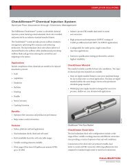
The Close Tolerance Press Fit Stop Collar (PFSC) is a new<br />
stop collar that addresses the need for tight clearance and<br />
close tolerance applications when passing casing<br />
attachments through severe restrictions. This new<br />
technology offers a unique design consisting of three slipon<br />
components, which, after assembly, provide outstanding<br />
holding force compared to conventional stop collars.<br />
Features<br />
• Rating—tested in accordance to API<br />
recommendations.<br />
• Description—comprises three components: (1) collet<br />
base with fingers (curved plates) that is axially split to<br />
conform to the curvature of the tubular and (2) sleeves.<br />
A hydraulic installation tool is required to assemble the<br />
components whereby the sleeves are pressed/forced on<br />
top of the fingers. The interference fit between the<br />
collet base fingers and the sleeves is engineered to<br />
provide optimum holding force.<br />
• Performance—outstanding holding force. Used when<br />
maximum holding forces are required. Stays in one<br />
piece, even when maximum holding force is exceeded.<br />
Applications<br />
• Engineered for tight clearance/close tolerance<br />
applications.<br />
• Ideal for under reamed holes sections.<br />
• Slim design allows for installation under SP-516 Series<br />
Close Tolerance Slip-on centralizer to allow for<br />
centralizer to be pulled in either direction.<br />
• Suitable for well environments up to 350°F+<br />
performance.<br />
• Compatible with all casing grades. Ideal for CRA<br />
tubulars.<br />
• Non-marking and non-scarring.<br />
• Can be located anywhere on flush casing joints.<br />
• Allows for rotation and reciprocation.<br />
• Casing running operations remain conventional with<br />
no interruptions.<br />
• Minimal pipe preparation<br />
Collet Base<br />
Fingers<br />
Sleeve<br />
PFSC Series SP21PF<br />
PFSC Series SP21PF and<br />
Recommended SP-516 Close Tolerance Centralizer<br />
11-27 Casing Attachments
Wall Scratchers and Wipers<br />
Scratchers and wipers help remove excess filter cake and<br />
gelled mud from the wellbore whenever the pipe moves. This<br />
action can provide better bonding surfaces for the cement<br />
and helps isolate one zone from another in the cemented<br />
area. Scratchers and the cable loops also act as steel<br />
reinforcement in the cement column. Scratchers also add<br />
localized turbulence during cementing operations. For best<br />
results, install reciprocating scratchers 2 to 3 ft apart between<br />
stop collars. Install reciprocating cable wipers 2 to 3 ft apart<br />
across the cementing interval. The looped cable design on<br />
the wiper helps remove excess filter cake, gelled mud, and bit<br />
cuttings from the wellbore wall for circulation out of the hole.<br />
Install the wiper by latching it around the casing, and then<br />
torque the Allen head bolt to approximately 25 to<br />
35 ft-lb. The looped cable wiper will serve as reinforcement<br />
steel in cement columns and will help clean the wellbore.<br />
During mud circulation and cementing, reciprocate the<br />
casing enough to scratch and wipe the entire zone.<br />
Hinged Wire Scratcher<br />
AOT Series 101<br />
Hinged Cable Type Reciprocating Wall<br />
Cleaner<br />
AOT Series 300<br />
Features<br />
• Rating—not governed by API.<br />
• Design appearance—has a hinged collar design that<br />
features a looped cable design.<br />
• Performance<br />
– Helps provide additional insurance for removal of<br />
excess filter cake, gelled mud, and bit cuttings from<br />
wellbore to be circulated from the hole.<br />
– Helps add more reinforcement and bonding to cement<br />
column.<br />
– Helps assist and prepare wellbore for cement job.<br />
• Applications—used in most types of well designs; for<br />
optimum results, casing string must be reciprocated.<br />
• Sizes available—2 3/8 to 20 in.<br />
• Minimum hole size—recommended minimum clearance<br />
between casing and hole size is 1 1/2 to 5 1/2 in.<br />
Features<br />
• Rating—not governed by API.<br />
• Design appearance—has a hinged collar design that<br />
features upwardly inclined woven wire cable finger<br />
designs.<br />
• Performance<br />
– Helps provide additional insurance for removal of<br />
excess filter cake, gelled mud, and bit cuttings from<br />
wellbore to be circulated from the hole.<br />
– Helps add more reinforcement and bonding to cement<br />
column.<br />
– Helps assist and prepare wellbore for cement job.<br />
• Applications—used in most types of well designs; for<br />
optimum results. casing string must be reciprocated.<br />
• Sizes available—2 3/8 to 20 in.<br />
• Minimum hole size—recommended minimum clearance<br />
between casing and hole size is 1 1/2 to 5 1/2 in.<br />
HAL24972<br />
HAL24960<br />
Series 101 Series 300<br />
Casing Attachments 11-28
Rotating Wipers<br />
Rotating wipers are available as a cable type design. Wipers<br />
are attached to the well casing to help remove filter cake<br />
and gelled mud from the wellbore whenever casing is<br />
rotated during cementing operations. Using today’s<br />
cementing software simulators, modeling results are<br />
showing rotation provides a better bonding environment<br />
for the cement and helps isolate one zone from another<br />
through the cemented interval. The wiper channel hugs the<br />
casing snugly and can be installed by welding to the casing<br />
or with Series 200 stop collars.<br />
Rotating Cable Wall Wipers<br />
AOT Series 333<br />
Features<br />
• Rating—not governed by API.<br />
• Design appearance—5-in. long looped cable wiper<br />
strip.<br />
• Performance—helps provide additional insurance for<br />
removal of excess filter cake, gelled mud, and bit<br />
cuttings from wellbore to be circulated from the hole.<br />
– Helps add more reenforcement and bonding to<br />
cement column.<br />
– Helps assist and prepare wellbore for cement job.<br />
– Large flow areas through and between the loops<br />
permit filter cake to pass.<br />
• Applications—used in most types of well designs; for<br />
optimum results, casing string must be rotated.<br />
• Sizes available—one size applicable to all well designs.<br />
• Minimum recommended hole size—at least 2 in. over<br />
pipe size.<br />
• Maximum effective diameter—5 1/2 in. over pipe size.<br />
Series 333 Rotating Cable Wiper<br />
Series 200 Stop Collar<br />
11-29 Casing Attachments
Cement Baskets<br />
Cement baskets are run on casing or liners above porous or<br />
weak formations that require protection from the hydrostatic<br />
pressure generated by the cement column. They can also be<br />
used to help support a cement column near the well surface<br />
while the cement sets. In stage-cementing operations, one<br />
basket is run on the joint just below the stage tool and<br />
another is run on the string above the tool. Some operators<br />
pump their first stage of cement above the lower basket and<br />
allow the cement to set while they circulate mud for the next<br />
stage. The bridge that is formed helps support the upper<br />
cement column.<br />
Metal Petal Cement Basket<br />
AOT Series 910<br />
Features<br />
• Rating—not governed by API<br />
• Design appearance—slip-on style made of high strength,<br />
flexible steel bows mounted on steel slip-on end collars<br />
with metal petals spot welded to one end of the collar.<br />
• Performance<br />
– Aids in premature cement hydration to help reduce<br />
hydrostatic fluid column above a loss zone or weak<br />
formation<br />
– Works similar in cementing applications like a coffee<br />
filter does in catching particles to form a bridge in the<br />
annulus to prevent cement from falling back<br />
• Applications<br />
– Used in most types of well designs<br />
– May be used in cased hole and openhole applications<br />
– The metal petals are convex shape for added strength<br />
and durability and afford great adaptability to expansion<br />
and contraction. This type of construction allows for<br />
the cement basket to be rotated and reciprocated if<br />
necessary. Baskets are typically installed using a 212<br />
stop collar inside the basket. For optimum results casing<br />
string must be reciprocated.<br />
• Sizes available—2 3/8 in. to 30 in.<br />
• Minimum hole size—recommended maximum<br />
clearance between casing and hole size is 1 1/2 in. to<br />
2 7/8 in.; custom applications available.<br />
Standard Canvas Cement Basket<br />
AOT Series 912<br />
Features<br />
• Rating—not governed by API.<br />
• Design appearance—slip-on style made of high strength,<br />
flexible steel staves, mounted on a steel slip-on ring with<br />
heavy duty canvas liners riveted to staves fabricated of<br />
high strength, flexible steel bows mounted on steel slipon<br />
end collars with metal petals spot welded to one end<br />
of the collar.<br />
• Performance<br />
– Aids premature cement hydration to help reduce<br />
hydrostatic fluid column above a loss zone or weak<br />
formation.<br />
– Works similar in cementing applications like a coffee<br />
filter does, catching particles to form a bridge in the<br />
annulus to prevent cement from falling back.<br />
• Applications<br />
– Used in most types of well designs.<br />
– Can be used in cased hole and openhole applications.<br />
– Basket should be allowed to travel on the joint of casing.<br />
Working casing past casing joint length will destroy the<br />
basket.<br />
• Sizes available—2 7/8 to 30 in.<br />
• Minimum hole size—recommended maximum<br />
clearance between casing and hole size is 1 1/2 to<br />
2 7/8 in.; custom applications available.<br />
HAL24968<br />
HAL24969<br />
Series 910 Series 912<br />
Casing Attachments 11-30
Casewell Drilling and Cementing Products<br />
<strong>Halliburton</strong> has used Casewell on selected projects and<br />
awarded tenders in the Eastern hemisphere. Casewell<br />
products are designed, assembled, tested, and inspected by<br />
its facility in India, which is equipped with modern<br />
machines and testing equipment, including heat treatment,<br />
state of art press shop, machine shop, paint shop, and are<br />
manufactured with rigid quality control. Quality<br />
management systems are fully practiced and adhered to as<br />
per API Specification Q1 and ISO 9001-2000.<br />
Casewell calculates the total load on centralizer at each<br />
deflection and prepares a load deflection curve using<br />
arithmetic average of force readings. This determines the<br />
restoring force specified in the API Specification10D. In<br />
addition to API testing, Casewell also performs the<br />
following test considering extreme conditions these<br />
products can encounter. Tensile stress testing on these<br />
centralizers is performed to help ensure that even a severely<br />
damaged centralizer will remain intact, rather than<br />
damaging the completion process. The compression tests<br />
are conducted to help ensure that even badly distorted<br />
centralizer bows will not fracture and leave metal<br />
fragments in the well.<br />
Offerings<br />
Non-welded Bow Spring Centralizer<br />
• Hinged non-weld bow spring centralizers.<br />
• Semi rigid non-weld bow spring centralizers.<br />
Welded Bow Spring Centralizer<br />
• Hinged welded bow spring centralizer.<br />
• Slip-on welded bow spring centralizer.<br />
• Rotating welded bow spring centralizer.<br />
The Casewell philosophy is to provide the best possible<br />
solution to any centralizing problem.<br />
Features<br />
• API certified products<br />
• Efficient management system<br />
• World-class infrastructure<br />
• High quality in production<br />
• Fully traceable QA/QC<br />
• ISO 9001, 14001, 18001 certified<br />
• Their strong and committed marketing, R&D, and<br />
operations teams continuously strive to make ever<br />
delivery on time.<br />
Slip-on, Hinged, Welded, and Non-welded Bow Spring Centralizers<br />
11-31 Casing Attachments
Rigid Positive Bow Centralizers<br />
• Hinged non-weld positive centralizer.<br />
• Slip-on positive welded spiralizer.<br />
• Heavy-duty slip-on welded spiralizer.<br />
Turbolizer Bow Spring Centralizers<br />
• Non-welded turbolizer<br />
• Welded turbolizer<br />
Solid Rigid Centralizers<br />
• Straight solid rigid centralizer<br />
• Spiral solid rigid centralizer<br />
Stop Collars<br />
• Hinged bolted stop collars.<br />
• Hinged spiral nail stop collars.<br />
• Hinged set screw stop collars.<br />
• Heavy-duty set screw stop collars.<br />
• Slip-on aluminum set screw stop collars.<br />
Rigid Positive Bow Centralizers<br />
Turbolizer and Semi Rigid Bow Spring Centralizers<br />
Solid Rigid Centralizers<br />
Stop Collars<br />
Casing Attachments 11-32
Ray Oil Tool Co. Cast Alloy Centralizers<br />
Ray Oil Tool centralizers are manufactured in Louisiana<br />
and Scotland by Ray Oil Tool Company Inc. in Broussard,<br />
Louisiana. <strong>Halliburton</strong> sells and is a provider of Ray Oil<br />
Tool Products. These solid blade centralizers are cast of a<br />
high-strength aluminum alloy, which provides high impact<br />
and shock resistance combined with high tensile and yield<br />
strength. These centralizers are also corrosion resistant.<br />
The solid centralizers are designed to slip easily over the<br />
pipe OD from the casing pin end. The centralizers should<br />
be installed between two stop rings or between a casing<br />
collar and stop ring. This method of installation allows the<br />
centralizer to move freely during running casing into the<br />
wellbore and during rotation or reciprocation of the casing<br />
during cementing operations.<br />
Solid Straight Blade Cast Alloy Centralizers<br />
Solid vane straight blade centralizers are designed to<br />
provide a fixed casing standoff, regardless of lateral load.<br />
This positive standoff helps ensure even distribution of<br />
cement around the well casing.<br />
HAL24992<br />
Solid centralizers can also be secured to the casing with set<br />
screws where it is not desirable to rotate or reciprocate the<br />
casing during cement operations.<br />
Features<br />
Straight Blade<br />
HAL31507<br />
Brand New, State-of-the-Art Drilling Rig on Construction Site in<br />
Oklahoma Ready for the Customer’s First Location<br />
• Rating—not governed by API.<br />
• Design appearance<br />
– Straight, smooth cast alloy ribs cast into solid bodies<br />
(one-piece castings).<br />
– Available with and without set screws.<br />
– Straight ribs offer 360° evenly spaced openhole<br />
coverage.<br />
• Performance<br />
– Provide positive casing standoff<br />
– Limited corrosion effects with a cast alloy product.<br />
– Reduced electrolysis due to non-similar metals.<br />
– Lighter in weight than steel versions.<br />
• Applications<br />
– Used in most types of well designs.<br />
– Most suited for horizontal and high directional well<br />
designs; favorable in cased hole situations.<br />
• Sizes available—4 1/2 to 20 in.; custom sizes available.<br />
• Actual OD—1/8 to 1 in. below stated hole size,<br />
depending on casing and hole size.<br />
• Minimum hole size—5 3/4 in.<br />
• Maximum hole size—25 in.<br />
• Length—8 to 30 in.<br />
11-33 Casing Attachments
Ray Oil Spiral Solid STAND-OFF<br />
Cast Alloy Centralizers<br />
The spiral STAND-OFF centralizer by Ray Oil is designed<br />
with a 360° overlapping solid vane to provide maximum<br />
wellbore contact and maximum wellbore fluid swirl. The<br />
spiral STAND-OFF centralizer is recommended to be used<br />
on shoe joints, through production zones, liner overlaps, and<br />
other areas where a good cement bond is essential. The<br />
recommended spacing through productive zones is every<br />
20 ft, using the left- and right-hand spiral design in every<br />
other sequence.<br />
Features<br />
• Rating—not governed by API.<br />
• Design appearance<br />
– Spiral smooth cast alloy ribs cast into solid bodies<br />
(one-piece castings).<br />
– Available with and without set screws.<br />
– Spiral ribs offer 360° evenly spaced openhole coverage.<br />
• Performance<br />
– Provide positive casing standoff<br />
– Limited corrosion effects with a cast alloy product.<br />
– Reduced electrolysis because of non-similar metals.<br />
– Lighter in weight than steel versions.<br />
• Applications<br />
– Used in most types of well designs.<br />
– Most suited for horizontal and high directional well<br />
designs; favorable in cased hole situations.<br />
• Sizes available—2 7/8 to 13 3/8 in.; custom<br />
sizes available.<br />
• Actual OD—1/8 to 1 in. below stated hole size,<br />
depending on casing and hole size,<br />
• Minimum hole size—4 1/2 in.<br />
• Maximum hole size—17 1/2 in.<br />
• Length—6 to 15 in.<br />
HAL24991<br />
Spiral Blade<br />
Ray Oil Tool Recommendations<br />
Aluminum straight blade vs. spiral blade<br />
• Straight blade advantages<br />
– Are the most wellbore friendly<br />
– Allow for self cleaning blades<br />
– Reduce drag while running casing<br />
• Spiral blade disadvantages<br />
– Acts as a plow scraping the wellbore.<br />
– Increases drag<br />
– Blades may clog<br />
– Same standoff as straight blade<br />
– Fluid agitation, turbulation, or swirling is recorded to<br />
be very short lived because pipe is never concentric<br />
to the wellbore.<br />
Ray Oil Tool Stop Rings<br />
The Ray Oil Tool Stop Ring design is a one-piece type that<br />
slips over the pin end of the pipe and secures in place with set<br />
screws. These stop rings have a superior holding force and<br />
are especially applicable in close tolerance situations.<br />
Features<br />
Stop Rings<br />
• Rating—tested in accordance to API recommendations.<br />
• Design appearance<br />
– One piece slip on with set screws.<br />
– Manufactured from high-grade tubular steel.<br />
• Performance—offer high performance to Ray Oil Tool<br />
aluminum centralizers.<br />
• Applications<br />
– Used in all types of well designs.<br />
– Sizes available—2 7/8 to 20 in. (custom sizes available).<br />
• Benefits<br />
– Flat end ring surface allows for smooth bearing surface<br />
to mated aluminum centralizers, allowing high<br />
performance during pipe rotation.<br />
Casing Attachments 11-34
• Options<br />
– Available with stainless steel set screws.<br />
– Available with one side beveled.<br />
– Available in aluminum and steel designs.<br />
• Aluminum vs. steel<br />
– Aluminum has a lower friction factor than steel.<br />
– Electrolysis occurs with dissimilar metals. Steel<br />
centralizers can cause casing electrolysis erosion.<br />
Aluminum is more the sacrificial metal.<br />
– Across production zones, aluminum has less<br />
perforation distortion.<br />
– Aluminum centralizers weigh 50% less than steel<br />
centralizers, which can be a transportation advantage.<br />
– Aluminum centralizers are manufactured by casting<br />
or extrusions, decreasing manufacturing time with<br />
constant quality assurance.<br />
Customer’s Mud Handling System on<br />
Newly Constructed Rig<br />
11-35 Casing Attachments
Downhole Products<br />
(a Varel International Energy Services Company)<br />
Downhole Products are specialist oilfield designers and<br />
manufacturers of the ultimate drag and torque reduction<br />
solid body zinc alloy centralizers, as widely used in the<br />
world’s demanding horizontal and extended-reach wells.<br />
Downhole Products is a British based company with<br />
headquarters in Aberdeen, Scotland, UK, and offices in the<br />
USA, Asia, and the Middle East. Downhole Products designs,<br />
manufactures, and supplies a wide range of casing accessories<br />
and completion tools. Its technologies are reinforced by<br />
dedicated engineering and manufacturing teams responsible<br />
for designing its selected range of products that <strong>Halliburton</strong><br />
offers, to include the Spir-O-Lizer centralizers, Spir-O-Lizer<br />
Blade Runner centralizers, and their matching series of limit<br />
clamps.<br />
Downhole Products’ commitment to quality and its<br />
customers is to deliver the best value to customers and<br />
markets by finding the optimum balance of performance,<br />
quality, and price, which, in turn, can result in the most<br />
effective solution to their completion requirements.<br />
Features<br />
• Complies with pertinent ISO and OHSAS requirements.<br />
• BS EN ISO 9001:2000 registered company.<br />
• Comply with the requirements of ISO 9001:2000 in<br />
addition to appropriate statutory and regulatory<br />
requirements.<br />
• Ongoing in-house research and development.<br />
• UK facility also accommodates Downhole Products<br />
engineering, with the provision of a purpose-built<br />
precision machine shop, with availability 24/7.<br />
• Downhole Products uses the latest CNC machines and<br />
other ancillary equipment.<br />
Offerings<br />
SPIR-O-LIZER Centralizers<br />
Spir-o-lizer centralizers are positive stand-off wellbore<br />
centralizers, specifically designed for casing, liners and sand<br />
control screens, to eliminate costly recurring problems,<br />
common in today’s demanding wells. Zinc-alloy centralizer<br />
affording proven torque and drag reduction, designed with<br />
maximum flow-by, helps ensure problem-free running with<br />
the lowest pressure drop of any centralizer available.<br />
Features<br />
• Maximum torque and drag reduction.<br />
• Spiral blade design assists hole cleaning and cement<br />
placement.<br />
• Maximum flow-by with self-cleaning blade design.<br />
• Unique non-sparking alloy<br />
• Exceptional wear resistance<br />
• Extends casing life<br />
• Designed to reduce operating costs.<br />
SPIR-O-LIZER<br />
Casing Attachments 11-36
The BLADERUNNER Centralizer<br />
Ultimate friction reduction, Spir-o-lizer centralizer<br />
performs equally in open or cased holes. Maximize drag<br />
reduction, minimize start up torque. Cost-effective<br />
alternative to roller type centralizers. Based on already<br />
proven design used in some of the world's most demanding<br />
wells completed in the past.<br />
The ultimate friction reduction Spir-o-lizer unit reduces<br />
both torque and drag with patented Ultra-Low Friction<br />
buttons and sleeves. It performs equally in open or cased<br />
hole situations and is a cost-effective alternative to roller<br />
type centralizers.<br />
The BLADERUNNER Centralizer<br />
BLADERUNNER LD Centralizer<br />
Maximum drag reduction can be achieved in cased/open<br />
holes using the BLADERUNNER LD (low drag) zinc alloy<br />
Spir-o-lizer centralizer enhanced with Ultra-Low Friction<br />
buttons. It eliminates moving parts and break down caused<br />
by ingress of cuttings.<br />
BLADERUNNER LD Centralizer<br />
BLADERUNNER LT Centralizer<br />
The BLADERUNNER LT (low torque) zinc alloy<br />
Spir-o-lizer centralizer incorporating the ultra-low friction<br />
sleeve minimizes startup torque and offers proven low<br />
friction zinc alloy construction with Spir-o-lizer features<br />
for rotating liners and casings.<br />
BLADERUNNER LT Centralizer<br />
Features<br />
• Works equally well in both cased hole and open hole,<br />
regardless of deviation.<br />
• Lower drag when running through cased hole sections<br />
and out into open hole through milled sections.<br />
• Provides enhanced clean up and cement placement<br />
properties.<br />
• Lowest friction coefficient of any centralizer available<br />
today.<br />
• The Blade Runner's patented Ultra-Low Friction<br />
buttons perform through even the longest casing runs.<br />
11-37 Casing Attachments