Turolla group 3 gear pumps - technical information - bibus sk
Turolla group 3 gear pumps - technical information - bibus sk
Turolla group 3 gear pumps - technical information - bibus sk

Create successful ePaper yourself
Turn your PDF publications into a flip-book with our unique Google optimized e-Paper software.
OpenCircuitGear<br />
<br />
MEMBER OF THE SAUER-DANFOSS GROUP<br />
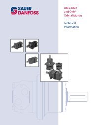
Group 3 Gear Pumps<br />
Technical Information<br />
System Requirements<br />
Reservoir<br />
The reservoir provides clean fluid, dissipates heat, removes entrained air, and allows<br />
for fluid volume changes associated with fluid expansion and cylinder differential<br />
volumes. A correctly sized reservoir accommodates maximum volume changes during<br />
all system operating modes. It promotes deaeration of the fluid as it passes through, and<br />
accommodates a fluid dwell-time between 60 and 180 seconds, allowing entrained air to<br />
escape.<br />
Minimum reservoir capacity depends on the volume required to cool and hold the oil<br />
from all retracted cylinders, allowing for expansion due to temperature changes. A fluid<br />
volume of 1 to 3 times the pump output flow (per minute) is satisfactory. The minimum<br />
reservoir capacity is 125% of the fluid volume.<br />
Install the suction line above the bottom of the reservoir to take advantage of gravity<br />
separation and prevent large foreign particles from entering the line. Cover the line with<br />
a 100-125 micron screen. The pump should be below the lowest expected fluid level.<br />
Put the return-line below the lowest expected fluid level to allow discharge into the<br />
reservoir for maximum dwell and efficient deaeration. A baffle (or baffles) between the<br />
return and suction lines promotes deaeration and reduces fluid surges.<br />
Line sizing<br />
Choose pipe sizes that accommodate minimum fluid velocity to reduce system noise,<br />
pressure drops, and overheating. This maximizes system life and performance. Design<br />
inlet piping that maintains continuous pump inlet pressure above 0.8 bar absolute<br />
during normal operation. The line velocity should not exceed the values in this table:<br />
Maximum line velocity<br />
Inlet<br />
2.5 [8.2]<br />
Outlet m/s [ft/sec] 5.0 [16.4]<br />
Return 3.0 [9.8]<br />
Most systems use hydraulic oil containing 10% dissolved air by volume. Under high inlet<br />
vacuum conditions the oil releases bubbles. They collapse when subjected to pressure,<br />
resulting in cavitation, causing adjacent metal surfaces to erode. Over-aeration is<br />
the result of air leaks on the inlet side of the pump, and flow-line restrictions. These<br />
include inadequate pipe sizes, sharp bends, or elbow fittings, causing a reduction of flow<br />
line cross sectional area. This problem will not occur if inlet vacuum and rated speed<br />
requirements are maintained, and reservoir size and location are adequate.<br />
L1016456 • June 2010 • Rev A<br />
13