Turolla group 3 gear pumps - technical information - bibus sk
Turolla group 3 gear pumps - technical information - bibus sk
Turolla group 3 gear pumps - technical information - bibus sk

You also want an ePaper? Increase the reach of your titles
YUMPU automatically turns print PDFs into web optimized ePapers that Google loves.
Group 3<br />
Gear Pumps<br />
<br />
OpenCircuitGear<br />
MEMBER OF THE SAUER-DANFOSS GROUP<br />
Technical<br />
Information
OpenCircuitGear<br />
<br />
MEMBER OF THE SAUER-DANFOSS GROUP<br />
Group 3 Gear Pumps<br />
Technical Information<br />
General Information<br />
History of revisions<br />
Table of revisions<br />
Date Page Changed Rev.<br />
28, June 2010 - First edition A<br />
Reference documents<br />
Literature reference for <strong>gear</strong> products<br />
Title Type Order number<br />
General Aluminum Gear Pumps and Motors Technical Information L1016238<br />
Group 1 Gear Pumps Technical Information L1016399<br />
Group 2 Gear Pumps Technical Information L1016341<br />
Group 1, 2 and 3 Gear Motors Technical Information L1016082<br />
Hydraulic Fluids and Lubricants Technical Information L1021414<br />
Experience with Biodegradable Hydraulic Fluids Technical Information L1021903<br />
© 2010 <strong>Turolla</strong> OpenCircuitGear. All rights reserved.<br />
<strong>Turolla</strong> OCG accepts no responsibility for possible errors in catalogs, brochures and other printed material. <strong>Turolla</strong> OCG reserves<br />
the right to alter its products without prior notice. This also applies to products already ordered provided that such alterations<br />
can be made without affecting agreed specifi cations. All trademarks in this material are properties of their respective owners.<br />
Sauer-Danfoss, <strong>Turolla</strong>, <strong>Turolla</strong> OpenCircuitGear, <strong>Turolla</strong> OCG, OpenCircuitGear, Fast Lane and PLUS+1 are trademarks of the<br />
Sauer-Danfoss Group.<br />
2<br />
L1016456 • June 2010 • Rev A
OpenCircuitGear<br />
<br />
MEMBER OF THE SAUER-DANFOSS GROUP<br />
Group 3 Gear Pumps<br />
Technical Information<br />
Contents<br />
General Information<br />
Overview............................................................................................................................................................ 4<br />
Features.............................................................................................................................................................. 4<br />
Pump displacements..................................................................................................................................... 4<br />
Group 3 <strong>gear</strong> <strong>pumps</strong>` attributes.......................................................................................................... 4<br />
SEP3NN......................................................................................................................................................... 5<br />
SNP3NN......................................................................................................................................................... 5<br />
Pump design..................................................................................................................................................... 5<br />
Gear pump in circuit...................................................................................................................................... 5<br />
Technical data.................................................................................................................................................. 6<br />
Determination of nominal pump sizes................................................................................................... 7<br />
Based on SI units/Based on US units.................................................................................................. 7<br />
Product Coding<br />
Model code....................................................................................................................................................... 8<br />
System Requirements<br />
Pressure............................................................................................................................................................10<br />
Speed................................................................................................................................................................10<br />
Hydraulic fluids..............................................................................................................................................11<br />
Temperature and viscosity........................................................................................................................11<br />
Filtration...........................................................................................................................................................12<br />
Filters............................................................................................................................................................12<br />
Selecting a filter.......................................................................................................................................12<br />
Reservoir..........................................................................................................................................................13<br />
Line sizing........................................................................................................................................................13<br />
Pump drive......................................................................................................................................................14<br />
Pump drive data form.................................................................................................................................15<br />
Pump life..........................................................................................................................................................16<br />
Sound levels....................................................................................................................................................17<br />
Pump Performance<br />
Pump performance graphs.......................................................................................................................18<br />
Product Options<br />
Shaft, flange, and port configurations...................................................................................................22<br />
Mounting flanges.........................................................................................................................................23<br />
Shaft options..................................................................................................................................................23<br />
Port configurations......................................................................................................................................24<br />
Porting..............................................................................................................................................................25<br />
Dimensions<br />
SNP3NN – 01FA, 01DA, 01BA / SEP3NN – 01BA..................................................................................26<br />
SNP3NN – 02FA, 02DA and 02BA.............................................................................................................27<br />
SNP3NN – 03FB, 03BB..................................................................................................................................28<br />
SNP3NN – 06DD, 06AA................................................................................................................................29<br />
SNP3NN and SEP3NN – 07SA, 07GA.......................................................................................................30<br />
L1016456 • June 2010 • Rev A<br />
3
OpenCircuitGear<br />
<br />
MEMBER OF THE SAUER-DANFOSS GROUP<br />
Group 3 Gear Pumps<br />
Technical Information<br />
General Information<br />
Overview<br />
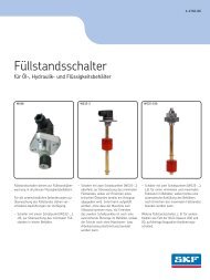
The <strong>Turolla</strong> OCG Group 3 is a range of peak performance fixed-displacement <strong>gear</strong><br />
<strong>pumps</strong>. Constructed of a high-strength extruded aluminum body with aluminum cover<br />
and flange, all <strong>pumps</strong> are pressure-balanced for exceptional efficiency.<br />
SNP3NN 07SA SEP3NN 07SA SEP3NN 07GA SNP3NN 01BA<br />
Features<br />
Group 3 <strong>gear</strong> <strong>pumps</strong>` attributes<br />
• Wide range of displacements from 22 to 90 cm 3<br />
/rev [from 1.34 to 5.49 in 3 /rev]<br />
• Continuous pressure rating up to 250 bar [3625 psi]<br />
-1<br />
• Speeds up to 3000 min (rpm)<br />
• SAE, DIN and European standard mounting flanges<br />
• High quality case hardened steel <strong>gear</strong>s<br />
• Multiple pump configurations in combination with SNP1NN, SNP2NN and SNP3NN<br />
Pump displacements<br />
Quick reference chart for pump displacements vs. rated pressure<br />
Rated pressure (bar)<br />
250<br />
200<br />
150<br />
100<br />
50<br />
SNP3NN<br />
SEP3NN<br />
0<br />
0 10 20 30 40 50 60 70 80 90 100<br />
Displacement (cm 3 /rev)<br />
4<br />
L1016456 • June 2010 • Rev A
OpenCircuitGear<br />
<br />
MEMBER OF THE SAUER-DANFOSS GROUP<br />
Group 3 Gear Pumps<br />
Technical Information<br />
General Information<br />
Pump design<br />
SEP3NN<br />
The SEP3NN <strong>gear</strong> pump is available in a limited displacement range from 22.0 to<br />
44.1 cm 3 /rev [from 1.34 to 2.69 in 3 /rev]. Suitable for applications where the pressure<br />
is lower than 210 bar [3045 psi], the SEP3NN range is released into SAE and European<br />
configurations. The overall length is reduced by 12 mm [0.47 in] in respect of the<br />
SNP3NN.<br />
SNP3NN<br />
The SNP3NN is available in the full<br />
displacement range from 22.0 to<br />
88.2 cm 3 /rev [from 1.34 to 5.38 in 3 /rev],<br />
and with higher pressure ratings than<br />
the SEP3NN. This is due to the pressure<br />
balance on each side of the <strong>gear</strong>s<br />
obtained with pressure-balance plates<br />
made in antifriction alloy that contribute<br />
to high volumetric efficiency and<br />
maximum sealing as well.<br />
SNP3NN 01BA (cut away)<br />
L1016456 • June 2010 • Rev A<br />
5
OpenCircuitGear<br />
<br />
MEMBER OF THE SAUER-DANFOSS GROUP<br />
Group 3 Gear Pumps<br />
Technical Information<br />
General Information<br />
Technical data<br />
Technical data for SNP3NN<br />
SNP3NN pump model<br />
Displacement<br />
Peak pressure<br />
Rated pressure<br />
cm 3 /rev<br />
[in 3 /rev]<br />
bar [psi]<br />
Frame size<br />
022 026 033 038 044 048 055 063 075 090<br />
22.1<br />
[1.35]<br />
270<br />
[3910]<br />
250<br />
[3625]<br />
Technical data for SEP3NN<br />
SEP3NN pump model<br />
Displacement<br />
Peak pressure<br />
Rated pressure<br />
cm 3 /rev<br />
[in 3 /rev]<br />
bar [psi]<br />
Frame size<br />
022 026 033 038 044<br />
22.1<br />
[1.35]<br />
230<br />
[3350]<br />
210<br />
[3045]<br />
26.2<br />
[1.60]<br />
230<br />
[3350]<br />
210<br />
[3045]<br />
33.1<br />
[2.02]<br />
230<br />
[3350]<br />
210<br />
[3045]<br />
37.9<br />
[2.32]<br />
230<br />
[3350]<br />
210<br />
[3045]<br />
44.1<br />
[2.69]<br />
200<br />
[2910]<br />
180<br />
[2610]<br />
Minimum speed<br />
1000 1000 1000 1000 800<br />
min -1 (rpm)<br />
Maximum speed 3000 3000 3000 2800 2600<br />
Weight<br />
26.2<br />
[1.60]<br />
270<br />
[3910]<br />
250<br />
[3625]<br />
Moment of inertia of<br />
rotating components<br />
Theoretical flow at<br />
maximum speed<br />
33.1<br />
[2.02]<br />
270<br />
[3910]<br />
250<br />
[3625]<br />
kg [lb]<br />
37.9<br />
[2.32]<br />
270<br />
[3910]<br />
250<br />
[3625]<br />
x 10 -6 kg•m 2<br />
[x 10 -6 lbf•ft 2 ]<br />
l/min<br />
[US gal/min]<br />
44.1<br />
[2.69]<br />
270<br />
[3910]<br />
250<br />
[3625]<br />
5.7<br />
[12.57]<br />
198<br />
[4698]<br />
66.3<br />
[17.5<br />
48.3<br />
[2.93]<br />
250<br />
[3625]<br />
230<br />
[3350]<br />
5.8<br />
[12.79]<br />
216<br />
[5126]<br />
78.6<br />
[20.8]<br />
55.1<br />
[3.36]<br />
250<br />
[3625]<br />
230<br />
[3350]<br />
63.4<br />
[3.87]<br />
230<br />
[3350]<br />
210<br />
[3045]<br />
6.1<br />
[13.45]<br />
246<br />
[5873]<br />
99.3<br />
[26.2]<br />
74.4<br />
[4.54]<br />
200<br />
[2910]<br />
180<br />
[2610]<br />
6.2<br />
[13.67]<br />
294.2<br />
[6981]<br />
113.7<br />
[30.0]<br />
88.2<br />
[5.38]<br />
170<br />
[2465]<br />
150<br />
[2175]<br />
Minimum speed<br />
800 800 800 800 800 800 800 600 600 600<br />
min -1 (rpm)<br />
Maximum speed 3000 3000 3000 3000 3000 3000 2500 2500 2500 2500<br />
Weight<br />
Moment of inertia of<br />
rotating components<br />
Theoretical flow at<br />
maximum speed<br />
kg [lb]<br />
x 10 -6 kg•m 2<br />
[x 10 -6 lbf•ft 2 ]<br />
l/min<br />
[US gal/min]<br />
6.8<br />
[15.0]<br />
198<br />
[4698]<br />
66.3<br />
[17.5]<br />
6.8<br />
[15.0]<br />
216<br />
[5126]<br />
78.6<br />
[20.8]<br />
7.2<br />
[15.8]<br />
246<br />
[5838]<br />
99.3<br />
[26.2]<br />
7.3<br />
[16.1]<br />
267,2<br />
[6340]<br />
113.7<br />
[30.0]<br />
7.5<br />
[16.5]<br />
294,2<br />
[6891]<br />
132.3<br />
[35.0]<br />
7.6<br />
[16.8]<br />
312,2<br />
[7408]<br />
144.9<br />
[38.3]<br />
7.8<br />
[17.3]<br />
342,3<br />
[8123]<br />
137.8<br />
[36.4]<br />
8.1<br />
[17.9]<br />
378,3<br />
[8977]<br />
158.5<br />
[41.8]<br />
8.5<br />
[18.7]<br />
426,4<br />
[10118]<br />
186<br />
[49.1]<br />
8.9<br />
[19.6]<br />
486,5<br />
[11545]<br />
220.5<br />
[58.3]<br />
6.4<br />
[14.11]<br />
312.2<br />
[7408]<br />
132.3<br />
[35.0]<br />
C Caution<br />
The rated and peak pressure mentioned are for <strong>pumps</strong> with flanged ports<br />
only. When threaded ports are required a de-rated performance has to be<br />
considered. To verify the compliance of an high pressure application with a<br />
threaded ports pump apply to a <strong>Turolla</strong> OCG representative.<br />
6<br />
L1016456 • June 2010 • Rev A
OpenCircuitGear<br />
<br />
MEMBER OF THE SAUER-DANFOSS GROUP<br />
Group 3 Gear Pumps<br />
Technical Information<br />
General Information<br />
Determination of<br />
nominal pump sizes<br />
Use these formulae to determine the nominal pump size for a specific application:<br />
Based on SI units<br />
Based on US units<br />
Output flow:<br />
Vg • n • η v<br />
Q = l/min<br />
1000<br />
Vg • n • η v<br />
Q = [US gal/min]<br />
231<br />
Input torque:<br />
M =<br />
Vg • ∆p<br />
20 • π • η m<br />
N•m<br />
M =<br />
Vg • ∆p<br />
2 • π • η m<br />
[lbf•in]<br />
Input power:<br />
M • n Q • ∆p<br />
P = = kW<br />
9550 600 • η t<br />
M • n Q • ∆p<br />
P = = [hp]<br />
63.025 1714 • η t<br />
Variables:<br />
SI units [US units]<br />
V g<br />
= Displacement per rev. cm 3 /rev [in 3 /rev]<br />
p HD<br />
= Outlet pressure bar [psi]<br />
p ND<br />
= Inlet pressure bar [psi]<br />
∆p = p HD<br />
– p ND<br />
bar [psi]<br />
n = Speed min -1 (rpm)<br />
η v<br />
= Volumetric efficiency<br />
η m<br />
= Mechanical (torque) efficiency<br />
η t<br />
= Overall efficiency (η v<br />
• η m<br />
)<br />
L1016456 • June 2010 • Rev A<br />
7
OpenCircuitGear<br />
<br />
MEMBER OF THE SAUER-DANFOSS GROUP<br />
Group 3 Gear Pumps<br />
Technical Information<br />
Product Coding<br />
Model code A B C D E F G H I J K L M N<br />
/ /<br />
A<br />
B<br />
Type<br />
SNP3NN<br />
SEP3NN<br />
Displacement<br />
Standard <strong>gear</strong> pump<br />
Medium pressure <strong>gear</strong> pump<br />
022 22.1 cm 3 /rev [1.35 in 3 /rev]<br />
026 26.2 cm 3 /rev [1.60 in 3 /rev]<br />
033 33.1 cm 3 /rev [2.02 in 3 /rev]<br />
038 37.9 cm 3 /rev [2.32 in 3 /rev]<br />
044 44.1 cm 3 /rev [2.69 in 3 /rev]<br />
048 48.3 cm 3 /rev [2.93 in 3 /rev]<br />
055 55.1 cm 3 /rev [3.36 in 3 /rev]<br />
063 63.4 cm 3 /rev [3.87 in 3 /rev]<br />
075 74.4 cm 3 /rev [4.54 in 3 /rev]<br />
090 88.2 cm 3 /rev [5.38 in 3 /rev]<br />
C<br />
D<br />
F<br />
Direction of rotation<br />
R Right hand (clockwise)<br />
L Left hand (counterclockwise)<br />
B For reversible motors<br />
Version<br />
N Standard <strong>gear</strong> pump<br />
Rear cover<br />
P1 Standard cover for pump<br />
E<br />
Mounting flange and drive <strong>gear</strong><br />
Code<br />
Description<br />
(Type of flange • type of drive <strong>gear</strong> • prefered ports for configuration)<br />
SNP3NN<br />
SEP3NN<br />
01FA European four bolt flange • Parallel shaft • European flanged ports –<br />
01BA European four bolt flange • Tapered 1:8 shaft • European flanged ports <br />
01DA European four bolt flange • Splined 15T 12x10 shaft • European flanged ports –<br />
02BA European four bolts flange • Tapered 1:8 shaft • European flanged ports –<br />
02DA European four bolts flange • DIN splined shaft • European flanged ports –<br />
02FA European four bolts flange • Parallel shaft • European flanged ports –<br />
03BB European four bolts flange • Tapered 1:8 shaft • European flanged ports –<br />
03FB European four bolts flange • Parallel shaft • European flanged ports –<br />
06AA German four bolts flange • Tapered 1:5 shaft • German standard ports –<br />
06DD German four bolts flange • DIN Splined shaft • German flanged ports –<br />
07GA SAE B flange • Parallel shaft • Vertical four bolt SAE flanged ports –<br />
07SA SAE B flange • SAE splined shaft • Vertical four bolt SAE flanged ports <br />
Legend:<br />
Standard<br />
❍ Optional<br />
– Not Available<br />
8<br />
L1016456 • June 2010 • Rev A
OpenCircuitGear<br />
<br />
MEMBER OF THE SAUER-DANFOSS GROUP<br />
Group 3 Gear Pumps<br />
Technical Information<br />
Product Coding<br />
Model code (continued) A B C D E F G H I J K L M N<br />
G<br />
Inlet port<br />
Code Description<br />
A2 8,5x22,23x47,63x ³/₈ -16UNC<br />
A3 25x26,19x52,37x ³/₈ -16UNC<br />
A4 31x30,18x58,72x 7/ ₁₆ -14UNC<br />
A5 37,5/27x35,7x69,85x ½ -13UNC<br />
B7 20x40xM6<br />
BA 18x55xM8<br />
BB 27x55xM8<br />
BC 36/27x55xM8<br />
C3 13,5x30xM6<br />
C7 20x40xM8<br />
CA 27x51xM10<br />
CD 36x62xM10<br />
E6 1 1/ ₁₆-12UN<br />
E8 1 5/ ₁₆-12UN<br />
E9 1 5/₈-12UN<br />
EA 1 ⁷/ ₈-12UN<br />
F5 ¾ GAS<br />
F6 1 GAS<br />
F7 1 ¼ GAS<br />
SAE flanged port<br />
Flanged port with thd holes in X pattern<br />
Flanged port with thd holes in + pattern<br />
Thd SAE O-ring boss port<br />
Threaded GAS (BSPP)<br />
H Outlet port<br />
For code letters and descriptions see the table above.<br />
I<br />
Port position and variant body<br />
NN Standard <strong>gear</strong> pump from catalogue<br />
L<br />
Set valve<br />
NNN<br />
V**<br />
No valve<br />
Integral RV-pressure setting.<br />
Pump speed for relief valve setting<br />
J<br />
Sealing<br />
N Standard Buna seal<br />
A Without shaft seal<br />
B VITON seals<br />
M<br />
Marking<br />
N<br />
A<br />
Z<br />
Standard marking<br />
Standard marking + customer code<br />
Without marking<br />
K<br />
Screws<br />
N Standard screws<br />
A Galvanized screws+nuts-washers<br />
B DACROMET/GEOMET screws<br />
N<br />
Mark position<br />
N<br />
A<br />
Standard marking position<br />
Mark on the bottom reffering to<br />
drive <strong>gear</strong><br />
L1016456 • June 2010 • Rev A<br />
9
OpenCircuitGear<br />
<br />
MEMBER OF THE SAUER-DANFOSS GROUP<br />
Group 3 Gear Pumps<br />
Technical Information<br />
System Requirements<br />
Pressure<br />
The inlet vacuum must be controlled in<br />
order to realize expected pump life and<br />
performance. The system design must<br />
meet inlet pressure requirements during<br />
all modes of operation. Expect lower<br />
inlet pressures during cold start. It should<br />
improve quickly as the fluid warms.<br />
Peak pressure is the highest intermittent<br />
pressure allowed. The relief valve<br />
overshoot (reaction time) determines<br />
peak pressure. It is assumed to occur for<br />
less than 100 ms. The illustration to the<br />
right shows peak pressure in relation to<br />
rated pressure and reaction time (100 ms<br />
maximum).<br />
Rated pressure is the average, regularly<br />
occurring, operating pressure that<br />
should yield satisfactory product life.<br />
The maximum machine load demand<br />
determines rated pressure. For all systems,<br />
the load should move below this pressure.<br />
Inlet pressure<br />
Max. continuous vacuum<br />
0.8 [23.6]<br />
bar abs.<br />
Max. intermittent vacuum 0.6 [17.7]<br />
[in. Hg]<br />
Max. pressure 3.0 [88.5]<br />
Time versus pressure<br />
Pressure<br />
Peak pressure<br />
Rated pressure<br />
Reaction time (100 ms max)<br />
Time<br />
System pressure is the differential of pressure between the outlet and inlet ports. It is a<br />
dominant operating variable affecting hydraulic unit life. High system pressure, resulting<br />
from high load, reduces expected life. System pressure must remain at, or below, rated<br />
pressure during normal operation to achieve expected life.<br />
Speed<br />
Maximum speed is the limit<br />
recommended by <strong>Turolla</strong> OCG for a<br />
particular <strong>gear</strong> pump when operating at<br />
rated pressure. It is the highest speed at<br />
which normal life can be expected.<br />
Speed versus pressure<br />
Rated<br />
The lower limit of operating speed is<br />
the minimum speed. It is the lowest<br />
speed at which normal life can be<br />
expected. The minimum speed increases<br />
as operating pressure increases. When<br />
operating under higher pressures,<br />
a higher minimum speed must be<br />
maintained, as illustrated to the right.<br />
Pressure<br />
P 1<br />
0<br />
N1<br />
N 2<br />
Speed<br />
Where:<br />
N 1<br />
= Minimum speed at 100 bar<br />
N 2<br />
= Minimum speed at 180 bar<br />
Operating<br />
envelope<br />
Max<br />
10<br />
L1016456 • June 2010 • Rev A
OpenCircuitGear<br />
<br />
MEMBER OF THE SAUER-DANFOSS GROUP<br />
Group 3 Gear Pumps<br />
Technical Information<br />
System Requirements<br />
Hydraulic fluids<br />
Ratings and data for SNP3NN and SEP3NN <strong>gear</strong> <strong>pumps</strong> are based on operating with<br />
premium hydraulic fluids containing oxidation, rust, and foam inhibitors. These fluids<br />
must possess good thermal and hydrolytic stability to prevent wear, erosion, and<br />
corrosion of internal components. They include:<br />
• Hydraulic fluids following DIN 51524, part 2 (HLP) and part 3 (HVLP) specifications<br />
• API CD engine oils conforming to SAE J183<br />
• M2C33F or G automatic transmission fluids<br />
• Certain agricultural tractor fluids<br />
Use only clean fluid in the pump and hydraulic circuit.<br />
C Caution<br />
Never mix hydraulic fluids.<br />
Please see <strong>Turolla</strong> OCG publication Hydraulic Fluids and Lubricants Technical<br />
Information, L1021414 for more <strong>information</strong>. Refer to publication Experience<br />
with Biodegradable Hydraulic Fluids Technical Information, L1021903 for<br />
<strong>information</strong> relating to biodegradable fluids.<br />
Temperature and<br />
Viscosity<br />
Temperature and viscosity requirements must be concurrently satisfied. Use<br />
petroleum / mineral-based fluids.<br />
High temperature limits apply at the inlet port to the pump. The pump should run at<br />
or below the maximum continuous temperature. The peak temperature is based on<br />
material properties. Don’t exceed it.<br />
Cold oil, generally, doesn’t affect the durability of pump components. It may affect the<br />
ability of oil to flow and transmit power. For this reason, keep the temperature at 16 °C<br />
[60 °F] above the pour point of the hydraulic fluid.<br />
Minimum (cold start) temperature relates to the physical properties of component<br />
materials.<br />
Minimum viscosity occurs only during brief occasions of maximum ambient temperature<br />
and severe duty cycle operation. You will encounter maximum viscosity only at cold start.<br />
During this condition, limit speeds until the system warms up. Size heat exchangers to<br />
keep the fluid within these limits. Test regularly to verify that these temperatures and<br />
viscosity limits aren’t exceeded. For maximum unit efficiency and bearing life, keep the<br />
fluid viscosity in the recommended viscosity range.<br />
Fluid viscosity<br />
Maximum (cold start)<br />
1000 [4600]<br />
mm 2 /s<br />
Recommended range 12-60 [66-290]<br />
[SUS]<br />
Minimum 10 [60]<br />
Temperature<br />
Minimum (cold start)<br />
-20 [-4]<br />
°C<br />
Maximum continuous 80 [176]<br />
[°F]<br />
Peak (intermittent) 90 [194]<br />
L1016456 • June 2010 • Rev A<br />
11
OpenCircuitGear<br />
<br />
MEMBER OF THE SAUER-DANFOSS GROUP<br />
Group 3 Gear Pumps<br />
Technical Information<br />
System Requirements<br />
Filtration<br />
Filters<br />
Use a filter that conforms to Class 22/18/13 of ISO 4406 (or better). It may be on the<br />
pump outlet (pressure filtration), inlet (suction filtration), or reservoir return (return-line<br />
filtration).<br />
Selecting a filter<br />
When selecting a filter, please consider:<br />
• contaminant ingression rate (determined by factors such as the number of actuators<br />
used in the system)<br />
• generation of contaminants in the system<br />
• required fluid cleanliness<br />
• desired maintenance interval<br />
• filtration requirements of other system components<br />
Measure filter efficiency with a Beta ratio (β X<br />
). For:<br />
• suction filtration, with controlled reservoir ingression, use a β 35-45<br />
= 75 filter<br />
• return or pressure filtration, use a pressure filtration with an efficiency of β 10<br />
= 75.<br />
β x<br />
ratio is a measure of filter efficiency defined by ISO 4572. It is the ratio of the number of particles greater<br />
than a given diameter ( “ X<br />
“ in microns) upstream of the filter to the number of these particles downstream of<br />
the filter.<br />
Fluid cleanliness level and β x<br />
ratio<br />
Fluid cleanliness level (per ISO 4406)<br />
Class 22/18/13 or better<br />
β x<br />
ratio (suction filtration) β 35-45<br />
= 75 and β 10<br />
= 2<br />
β x<br />
ratio (pressure or return filtration) β 10<br />
= 75<br />
Recommended inlet screen size<br />
100-125 µm [0.004-0.005 in]<br />
The filtration requirements for each system are unique. Evaluate filtration system<br />
capacity by monitoring and testing prototypes.<br />
12<br />
L1016456 • June 2010 • Rev A
OpenCircuitGear<br />
<br />
MEMBER OF THE SAUER-DANFOSS GROUP<br />
Group 3 Gear Pumps<br />
Technical Information<br />
System Requirements<br />
Reservoir<br />
The reservoir provides clean fluid, dissipates heat, removes entrained air, and allows<br />
for fluid volume changes associated with fluid expansion and cylinder differential<br />
volumes. A correctly sized reservoir accommodates maximum volume changes during<br />
all system operating modes. It promotes deaeration of the fluid as it passes through, and<br />
accommodates a fluid dwell-time between 60 and 180 seconds, allowing entrained air to<br />
escape.<br />
Minimum reservoir capacity depends on the volume required to cool and hold the oil<br />
from all retracted cylinders, allowing for expansion due to temperature changes. A fluid<br />
volume of 1 to 3 times the pump output flow (per minute) is satisfactory. The minimum<br />
reservoir capacity is 125% of the fluid volume.<br />
Install the suction line above the bottom of the reservoir to take advantage of gravity<br />
separation and prevent large foreign particles from entering the line. Cover the line with<br />
a 100-125 micron screen. The pump should be below the lowest expected fluid level.<br />
Put the return-line below the lowest expected fluid level to allow discharge into the<br />
reservoir for maximum dwell and efficient deaeration. A baffle (or baffles) between the<br />
return and suction lines promotes deaeration and reduces fluid surges.<br />
Line sizing<br />
Choose pipe sizes that accommodate minimum fluid velocity to reduce system noise,<br />
pressure drops, and overheating. This maximizes system life and performance. Design<br />
inlet piping that maintains continuous pump inlet pressure above 0.8 bar absolute<br />
during normal operation. The line velocity should not exceed the values in this table:<br />
Maximum line velocity<br />
Inlet<br />
2.5 [8.2]<br />
Outlet m/s [ft/sec] 5.0 [16.4]<br />
Return 3.0 [9.8]<br />
Most systems use hydraulic oil containing 10% dissolved air by volume. Under high inlet<br />
vacuum conditions the oil releases bubbles. They collapse when subjected to pressure,<br />
resulting in cavitation, causing adjacent metal surfaces to erode. Over-aeration is<br />
the result of air leaks on the inlet side of the pump, and flow-line restrictions. These<br />
include inadequate pipe sizes, sharp bends, or elbow fittings, causing a reduction of flow<br />
line cross sectional area. This problem will not occur if inlet vacuum and rated speed<br />
requirements are maintained, and reservoir size and location are adequate.<br />
L1016456 • June 2010 • Rev A<br />
13
OpenCircuitGear<br />
<br />
MEMBER OF THE SAUER-DANFOSS GROUP<br />
Group 3 Gear Pumps<br />
Technical Information<br />
System Requirements<br />
Pump drive<br />
Shaft options for Group 3 <strong>gear</strong> <strong>pumps</strong> include tapered, splined, or parallel shafts. They<br />
are suitable for a wide range of direct and indirect drive applications for radial and thrust<br />
loads.<br />
Plug-in drives, acceptable only with<br />
a splined shaft, can impose severe radial<br />
loads when the mating spline is rigidly<br />
supported. Increasing spline clearance<br />
does not alleviate this condition.<br />
Pilot cavity<br />
Mating spline<br />
Use plug-in drives if the concentricity<br />
between the mating spline and pilot<br />
diameter is within 0.1 mm [0.004 in].<br />
Lubricate the drive by flooding it with oil.<br />
A 3-piece coupling minimizes radial or<br />
thrust shaft loads.<br />
Ø 0.1 [0.004]<br />
P101 002E<br />
CCaution<br />
In order to avoid spline shaft damages it is recommended to use carburised<br />
and hardened steel couplings with 80-82 HRA surface hardness.<br />
Allowable radial shaft loads are a function of the load position, load orientation, and<br />
operating pressure of the hydraulic pump. All external shaft loads have an effect on<br />
bearing life, and may affect pump performance.<br />
In applications where external shaft loads can’t be avoided, minimize the impact on the<br />
pump by optimizing the orientation and magnitude of the load. Don’t use splined shafts<br />
for belt or <strong>gear</strong> drive applications. A spring-loaded belt tension-device is recommended<br />
for belt drive applications to avoid excessive tension. Avoid thrust loads in either direction.<br />
Contact <strong>Turolla</strong> OCG if continuously applied external radial or thrust loads occur.<br />
14<br />
L1016456 • June 2010 • Rev A
OpenCircuitGear<br />
<br />
MEMBER OF THE SAUER-DANFOSS GROUP<br />
Group 3 Gear Pumps<br />
Technical Information<br />
System Requirements<br />
Pump drive data form<br />
Photocopy this page and fax the complete form to your <strong>Turolla</strong> OCG representative for<br />
an assistance in applying <strong>pumps</strong> with belt or <strong>gear</strong> drive. This illustration shows a pump<br />
with counterclockwise orientation:<br />
Optimal radial load position<br />
90 o α a<br />
Inlet port<br />
180 o 90 o<br />
180 o 0 o<br />
0 o<br />
Inlet port<br />
270 o<br />
270 o<br />
P<br />
a<br />
a<br />
dw<br />
dw<br />
Application data<br />
Item Value Unit<br />
Pump displacement<br />
cm 3 /rev [in 3 /rev]<br />
Rated system pressure<br />
Relief valve setting<br />
bar psi<br />
Pump shaft rotation left right<br />
Pump minimum speed<br />
min -1 (rpm)<br />
Pump maximum speed<br />
Drive <strong>gear</strong> helix angle (<strong>gear</strong> drive only)<br />
degree<br />
Belt type (<strong>gear</strong> drive only) V notch<br />
Belt tension (<strong>gear</strong> drive only) P N lbf<br />
Angular orientation of <strong>gear</strong> or belt to inlet port α degree<br />
Pitch diameter of <strong>gear</strong> or pulley d w<br />
mm in<br />
Distance from flange to center of <strong>gear</strong> or pulley a<br />
L1016456 • June 2010 • Rev A<br />
15
OpenCircuitGear<br />
<br />
MEMBER OF THE SAUER-DANFOSS GROUP<br />
Group 3 Gear Pumps<br />
Technical Information<br />
System Requirements<br />
Pump life<br />
Pump life is a function of speed, system pressure, and other system parameters (such as<br />
fluid quality and cleanliness).<br />
All <strong>Turolla</strong> OCG <strong>gear</strong> <strong>pumps</strong> use hydrodynamic journal bearings that have an oil film<br />
maintained between the <strong>gear</strong> / shaft and bearing surfaces at all times. If the oil film<br />
is sufficiently sustained through proper system maintenance and operating within<br />
recommended limits, long life can be expected.<br />
B 10<br />
life expectancy number is generally associated with rolling element<br />
bearings.<br />
It does not exist for hydrodynamic bearings.<br />
High pressure, resulting from high loads, impacts pump life. When submitting an<br />
application for review, provide machine duty cycle data that includes percentages of<br />
time at various loads and speeds. We strongly recommend a prototype testing program<br />
to verify operating parameters and their impact on life expectancy before finalizing any<br />
system design.<br />
16<br />
L1016456 • June 2010 • Rev A
OpenCircuitGear<br />
<br />
MEMBER OF THE SAUER-DANFOSS GROUP<br />
Group 3 Gear Pumps<br />
Technical Information<br />
System Requirements<br />
Sound levels<br />
Fluid power systems are inherent generators of noise. As with many high power density<br />
devices, noise is an unwanted side affect. However, there are many techniques available<br />
to minimize noise from fluid power systems. To apply these methods effectively, it is<br />
necessary to understand how the noise is generated and how it reaches the listener.<br />
The noise energy can be transmitted away from its source as either fluid borne noise<br />
(pressure ripple) or as structure borne noise.<br />
Pressure ripple is the result of the number of pumping elements (<strong>gear</strong> teeth) delivering<br />
oil to the outlet and the pump’s ability to gradually change the volume of each pumping<br />
element from low to high pressure. In addition, the pressure ripple is affected by the<br />
compressibility of the oil as each pumping element discharges into the outlet of the<br />
pump. Pressure pulsations will travel along the hydraulic lines at the speed of sound<br />
(about 1400 m/s in oil) until affected by a change in the system such as an elbow fitting.<br />
Thus the pressure pulsation amplitude varies with overall line length and position.<br />
Structure borne noise may be transmitted wherever the pump casing is connected<br />
to the rest of the system. The manner in which one circuit component responds to<br />
excitation depends on its size, form, and manner in which it is mounted or supported.<br />
Because of this excitation, a system line may actually have a greater noise level than the<br />
pump. To reduce this excitation, use flexible hoses in place of steel plumbing. If steel<br />
plumbing must be used, clamping of lines is recommended. To minimize other structure<br />
borne noise, use flexible (rubber) mounts.<br />
The accompanying graph shows typical sound pressure levels for SNP2NN <strong>pumps</strong><br />
(with SAE A flange, and spline shaft in plug in drive) measured in dB (A) at 1 m [3.28 ft]<br />
from the unit in a semi-anechoic chamber. Anechoic levels can be estimated by<br />
subtracting 3 dB (A) from these values.<br />
Contact your <strong>Turolla</strong> OCG representative for assistance with system noise<br />
control.<br />
L1016456 • June 2010 • Rev A<br />
17
OpenCircuitGear<br />
<br />
MEMBER OF THE SAUER-DANFOSS GROUP<br />
Group 3 Gear Pumps<br />
Technical Information<br />
Pump Performance<br />
Pump performance<br />
graphs<br />
The graphs on the next few pages provide typical output flow and input power for<br />
Group 3 <strong>pumps</strong> at various working pressures. Data were taken using ISO VG46 petroleum<br />
/mineral based fluid at 50 °C [122 °F] (viscosity = 28 mm2/s [132 SUS]).<br />
SNP3NN/022 pump performance graph<br />
70 [18.5]<br />
SNP3NN/026 pump performance graph<br />
80 [21.1]<br />
60 [15.8]<br />
SNP3NN/022<br />
70 [18.5]<br />
SNP3NN/026<br />
Flow l/min [US gal/min]<br />
50 [13.2]<br />
40 [10.6]<br />
30 [7.9]<br />
7 bar<br />
250 bar<br />
250 bar<br />
Power kW [hp]<br />
30 [40.2]<br />
Flow l/min [US gal/min]<br />
60 [15.8]<br />
50 [13.2]<br />
40 [10.6]<br />
30 [7.9]<br />
7 bar<br />
250 bar<br />
250 bar<br />
Power kW [hp]<br />
40 [53.6]<br />
30 [40.2]<br />
20<br />
10<br />
[5.3]<br />
[2.6]<br />
150 bar<br />
100 bar<br />
20 [16.8]<br />
10 [13.4]<br />
20<br />
10<br />
[5.3]<br />
[2.6]<br />
150 bar<br />
100 bar<br />
20 [16.8]<br />
10 [13.4]<br />
0<br />
0<br />
0 500 1000 1500 2000 2500 3000<br />
Speed min -1 (rpm)<br />
0<br />
0<br />
0 500 1000 1500 2000 2500 3000<br />
Speed min -1 (rpm)<br />
SNP3NN/033 pump performance graph<br />
SNP3NN/038 pump performance graph<br />
110 [29.0]<br />
100 [26.4]<br />
90 [23.8]<br />
SNP3NN/033<br />
7 bar<br />
110 [29.0]<br />
100 [26.4]<br />
SNP3NN/038<br />
7 bar<br />
Flow l/min [US gal/min]<br />
80 [21.1]<br />
70 [18.5]<br />
60 [15.8]<br />
50 [13.2]<br />
40 [10.6]<br />
250 bar<br />
250 bar<br />
Power kW [hp]<br />
50 [67.1]<br />
40 [53.6]<br />
Flow l/min [US gal/min]<br />
90 [23.8]<br />
80 [21.1]<br />
70 [18.5]<br />
60 [15.8]<br />
50 [13.2]<br />
40 [10.6]<br />
250 bar<br />
250 bar<br />
Power kW [hp]<br />
60 [80.5]<br />
50 [67.1]<br />
40 [53.6]<br />
30<br />
20<br />
[7.9]<br />
[5.3]<br />
150 bar<br />
100 bar<br />
30 [40.2]<br />
20 [16.8]<br />
30 [7.9]<br />
20 [5.3]<br />
150 bar<br />
100 bar<br />
30 [40.2]<br />
20 [16.8]<br />
10<br />
[2.6]<br />
10 [13.4]<br />
10 [2.6]<br />
10 [13.4]<br />
0<br />
0<br />
0 500 1000 1500 2000 2500 3000<br />
Speed min -1 (rpm)<br />
0<br />
0<br />
0 500 1000 1500 2000 2500 3000<br />
Speed<br />
-1<br />
min (rpm)<br />
18<br />
L1016456 • June 2010 • Rev A
OpenCircuitGear<br />
<br />
MEMBER OF THE SAUER-DANFOSS GROUP<br />
Group 3 Gear Pumps<br />
Technical Information<br />
Pump Performance<br />
Pump performance graphs (continued)<br />
SNP3NN/044 pump performance graph<br />
140 [37.0]<br />
SNP3NN/048 pump performance graph<br />
140 [37.0]<br />
130 [34.3]<br />
120 [31.7]<br />
SNP3NN/044<br />
7 bar<br />
130 [34.3]<br />
120 [31.7]<br />
SNP3NN/048<br />
7 bar<br />
110 [29.0]<br />
100 [26.4]<br />
250 bar<br />
110 [29.0]<br />
100 [26.4]<br />
250 bar<br />
Flow l/min [US gal/min]<br />
90 [23.8]<br />
80 [21.1]<br />
70 [18.5]<br />
60 [15.8]<br />
50 [13.2]<br />
250 bar<br />
Power kW [hp]<br />
60 [80.5]<br />
50 [67.1]<br />
Flow l/min [US gal/min]<br />
90 [23.8]<br />
80 [21.1]<br />
70 [18.5]<br />
60 [15.8]<br />
50 [13.2]<br />
250 bar<br />
Power kW [hp]<br />
60 [80.5]<br />
50 [67.1]<br />
40 [10.6]<br />
30 [7.9]<br />
20 [5.3]<br />
150 bar<br />
100 bar<br />
40 [53.6]<br />
30 [40.2]<br />
20 [16.8]<br />
40 [10.6]<br />
30 [7.9]<br />
20 [5.3]<br />
150 bar<br />
100 bar<br />
40 [53.6]<br />
30 [40.2]<br />
20 [16.8]<br />
10<br />
[2.6]<br />
10 [13.4]<br />
10<br />
[2.6]<br />
10 [13.4]<br />
0<br />
0<br />
0 500 1000 1500 2000 2500 3000<br />
Speed min -1 (rpm)<br />
0<br />
0<br />
0 500 1000 1500 2000 2500 3000<br />
Speed min -1 (rpm)<br />
SNP3NN/055 pump performance graph<br />
150 [39.6]<br />
SNP3NN/063 pump performance graph<br />
160 [42.3]<br />
140 [37.0]<br />
130 [34.3]<br />
SNP3NN/055<br />
140 [37.0]<br />
SNP3NN/063<br />
Flow l/min [US gal/min]<br />
120 [31.7]<br />
110 [29.0]<br />
100 [26.4]<br />
90 [23.8]<br />
80 [21.1]<br />
70 [18.5]<br />
60 [15.8]<br />
50 [13.2]<br />
40 [10.6]<br />
30 [7.9]<br />
20 [5.3]<br />
7 bar<br />
230 bar<br />
150 bar<br />
230 bar<br />
100 bar<br />
Power kW [hp]<br />
60 [80.5]<br />
50 [67.1]<br />
40 [53.6]<br />
30 [40.2]<br />
20 [16.8]<br />
Flow l/min [US gal/min]<br />
120 [31.7]<br />
100 [26.4]<br />
80 [21.1]<br />
60 [15.8]<br />
40 [10.6]<br />
20 [5.3]<br />
7 bar<br />
210 bar<br />
150 bar<br />
210 bar<br />
100 bar<br />
Power kW [hp]<br />
60 [80.5]<br />
40 [53.6]<br />
20 [16.8]<br />
10<br />
[2.6]<br />
10 [13.4]<br />
0<br />
0<br />
0 500 1000 1500 2000 2500 3000<br />
Speed min -1 (rpm)<br />
0<br />
0<br />
0 500 1000 1500 2000 2500 3000<br />
Speed min -1 (rpm)<br />
L1016456 • June 2010 • Rev A<br />
19
OpenCircuitGear<br />
<br />
MEMBER OF THE SAUER-DANFOSS GROUP<br />
Group 3 Gear Pumps<br />
Technical Information<br />
Pump Performance<br />
Pump performance graphs (continued)<br />
SNP3NN/075 pump performance graph<br />
200 [52.8]<br />
SNP3NN/090 pump performance graph<br />
180 [47.6]<br />
SNP3NN/075<br />
220 [58.1]<br />
SNP3NN/090<br />
Flow l/min [US gal/min]<br />
Flow l/min [US gal/min]<br />
160 [42.3]<br />
140 [37.0]<br />
120 [31.7]<br />
100 [26.4]<br />
80 [21.1]<br />
80 [107.3]<br />
60 [15.8]<br />
40 [10.6]<br />
7 bar<br />
180 bar<br />
180 bar<br />
100 bar<br />
210 bar<br />
150 bar<br />
7 bar<br />
60 [80.5]<br />
40 [53.6]<br />
20 [5.3]<br />
0<br />
20 [16.8]<br />
0<br />
0 500 1000 1500 2000 2500 3000<br />
Speed min -1 (r pm)<br />
SEP3NN/022 pump performance graph<br />
70 [18.5]<br />
SEP3NN/022<br />
60 [15.8]<br />
50 [13.2]<br />
40 [10.6]<br />
30 [7.9]<br />
30 [40.2]<br />
Power kW [hp]<br />
Power kW [hp]<br />
Flow l/min [US gal/min] Flow l/min [US gal/min]<br />
200 [52.8]<br />
180 [47.6]<br />
160 [42.3]<br />
140 [37.0]<br />
120 [160.9]<br />
120 [31.7]<br />
100 [134.1]<br />
100 [26.4]<br />
80 [21.1]<br />
60 [15.8]<br />
140 bar<br />
100 bar<br />
140 bar<br />
40 [53.6]<br />
40 [10.6]<br />
20 [5.3]<br />
0<br />
20 [16.8]<br />
0<br />
0 500 1000 1500 2000 2500 3000<br />
Speed min -1 (r pm)<br />
SEP3NN/026 pump performance graph<br />
80 [21.1]<br />
SEP3NN/026<br />
70 [18.5]<br />
60 [15.8]<br />
50 [13.2]<br />
40 [10.6]<br />
7 bar<br />
210 bar<br />
7 bar<br />
80 [107.3]<br />
60 [80.5]<br />
30 [7.9]<br />
30 [40.2]<br />
Power kW [hp]<br />
Power kW [hp]<br />
20<br />
10<br />
[5.3]<br />
[2.6]<br />
210 bar<br />
150 bar<br />
100 bar<br />
20 [16.8]<br />
10 [13.4]<br />
20<br />
10<br />
[5.3]<br />
[2.6]<br />
210 bar<br />
150 bar<br />
100 bar<br />
20 [16.8]<br />
10 [13.4]<br />
0<br />
0<br />
0 500 1000 1500 2000 2500 3000<br />
Speed min -1 (r pm)<br />
0<br />
0<br />
0 500 1000 1500 2000 2500 3000<br />
Speed min -1 (r pm)<br />
20<br />
L1016456 • June 2010 • Rev A
OpenCircuitGear<br />
<br />
MEMBER OF THE SAUER-DANFOSS GROUP<br />
Group 3 Gear Pumps<br />
Technical Information<br />
Pump Performance<br />
Pump performance graphs (continued)<br />
SEP3NN/033 pump performance graph<br />
SEP3NN/038 pump performance graph<br />
100 [26.4]<br />
90 [23.8]<br />
80 [21.1]<br />
70 [18.5]<br />
SEP3NN/033<br />
7 bar<br />
100 [26.4]<br />
90 [23.8]<br />
80 [21.1]<br />
SEP3NN/038<br />
7 bar<br />
Flow l/min [US gal/min]<br />
60 [15.8]<br />
50 [13.2]<br />
40 [10.6]<br />
210 bar<br />
Power kW [hp]<br />
Flow l/min [US gal/min]<br />
70 [18.5]<br />
60 [15.8]<br />
50 [13.2]<br />
40 [10.6]<br />
210 bar<br />
Power kW [hp]<br />
40 [53.6]<br />
30<br />
20<br />
[7.9]<br />
[5.3]<br />
210 bar<br />
150 bar<br />
100 bar<br />
30 [40.2]<br />
20 [16.8]<br />
30<br />
20<br />
[7.9]<br />
[5.3]<br />
210 bar<br />
150 bar<br />
100 bar<br />
30 [40.2]<br />
20 [16.8]<br />
10<br />
[2.6]<br />
10 [13.4]<br />
10<br />
[2.6]<br />
10 [13.4]<br />
0<br />
0<br />
0 500 1000 1500 2000 2500 3000 3500<br />
Speed min -1 (rpm)<br />
0<br />
0<br />
0 500 1000 1500 2000 2500 3000<br />
Speed<br />
min<br />
-1<br />
(rpm)<br />
SEP3NN/044 pump performance graph<br />
120 [31.7]<br />
110 [29.0]<br />
100 [26.4]<br />
SEP3NN/044<br />
90 [23.8]<br />
Flow l/min [US gal/min]<br />
80 [21.1]<br />
70 [18.5]<br />
60 [15.8]<br />
50 [13.2]<br />
[10.6]<br />
40<br />
[7.9]<br />
30<br />
[5.3]<br />
20<br />
[2.6]<br />
10<br />
0<br />
7 bar<br />
180 bar<br />
180 bar<br />
150 bar<br />
100 bar<br />
Power kW [hp]<br />
40 [53.6]<br />
30 [40.2]<br />
20 [16.8]<br />
10 [13.4]<br />
0<br />
0 500 1000 1500 2000 2500 3000<br />
Speed<br />
min<br />
-1 (rpm)<br />
L1016456 • June 2010 • Rev A<br />
21
OpenCircuitGear<br />
<br />
MEMBER OF THE SAUER-DANFOSS GROUP<br />
Group 3 Gear Pumps<br />
Technical Information<br />
Product Options<br />
Shaft, flange, and port configurations<br />
Pump Code Flange Shaft Port<br />
SEP3NN<br />
SNP3NN<br />
01BA<br />
pilot Ø 50.8 mm [2.0 in]<br />
European 01, 4-bolt<br />
1:8 tapered<br />
European flanged<br />
port + pattern<br />
SNP3NN<br />
02BA<br />
pilot Ø 50.8 mm [2.0 in]<br />
European 02, 4-bolt<br />
1:8 tapered<br />
European flanged<br />
port + pattern<br />
SNP3NN<br />
03BB<br />
pilot Ø 60.3 mm [2.374 in]<br />
European 03, 4-bolt<br />
1:8 tapered<br />
European flanged<br />
port + pattern<br />
SNP3NN<br />
06AA<br />
pilot Ø 105 mm [4.133 in]<br />
German, 4-bolt<br />
1:5 tapered<br />
German std ports<br />
port X pattern<br />
SEP3NN<br />
SNP3NN<br />
01FA<br />
pilot Ø 50.8 mm [2.0 in]<br />
European 01, 4-bolt<br />
Ø 20 mm [0.787 in]<br />
parallel<br />
European flanged<br />
port + pattern<br />
SNP3NN<br />
02FA<br />
pilot Ø 50.8 mm [2.0 in]<br />
European 02, 4-bolt<br />
Ø 20 mm [0.787 in]<br />
parallel<br />
European flanged<br />
port + pattern<br />
SNP3NN<br />
03FB<br />
pilot Ø 60.3 mm [2.374 in]<br />
European 03, 4-bolt<br />
Ø 22 mm [0.866 in]<br />
parallel<br />
European flanged<br />
port + pattern<br />
SEP3NN<br />
SNP3NN<br />
07GA<br />
pilot Ø 101.6 mm [4.0 in]<br />
SAE B, 2-bolt<br />
Ø 22.225 mm [0.875 in]<br />
parallel<br />
Vertical four bolt<br />
flanged port<br />
SNP3NN<br />
01DA<br />
pilot Ø 50.8 mm [2.0 in]<br />
European 01, 4-bolt<br />
Splined shaft<br />
13T - m 1.60<br />
DIN 5482-B22x19<br />
European flanged<br />
port + pattern<br />
SNP3NN<br />
02DA<br />
pilot Ø 50.8 mm [2.0 in]<br />
European 02, 4-bolt<br />
Splined shaft<br />
13T - m 1.60<br />
DIN 5482-B22x19<br />
European flanged<br />
port + pattern<br />
SNP3NN<br />
06DD<br />
pilot Ø 105 mm [4.0 in]<br />
German, 4-bolt<br />
Splined shaft<br />
15T - m 1.75<br />
DIN 5482-B28x25<br />
German std ports<br />
port X pattern<br />
SEP3NN<br />
SNP3NN<br />
07SA<br />
pilot Ø 101.6 mm [4.0 in]<br />
SAE B, 2-bolt<br />
Splined shaft<br />
SAE J498<br />
13T - 16/32DP<br />
Vertical four bolt<br />
flanged port<br />
22<br />
L1016456 • June 2010 • Rev A
OpenCircuitGear<br />
<br />
MEMBER OF THE SAUER-DANFOSS GROUP<br />
Group 3 Gear Pumps<br />
Technical Information<br />
Product Options<br />
Mounting flanges<br />
<strong>Turolla</strong> OCG offers many types of industry standard mounting flanges. This table shows<br />
order codes for each available mounting flange and its intended use:<br />
Flange availability<br />
A B C D E F G H I J K L M N<br />
/ /<br />
Code Description<br />
01<br />
02<br />
European 50.8 mm [2.0 in] 4-bolt<br />
03 European 60.3 mm [2.374 in] 4-bolt<br />
06 German 105 mm [4.134 in] 4-bolt<br />
07 SAE B 2-bolt<br />
Shaft options<br />
Direction is viewed facing the shaft. Group 3 <strong>pumps</strong> are available with a variety of<br />
splined, parallel, and tapered shaft ends. Not all shaft styles are available with all flange<br />
styles.<br />
Shaft availability and nominal torque capability<br />
A B C D E F G H I J K L M N<br />
/ /<br />
Shaft<br />
Mounting flange code with maximum torque in Nm [lb•in]<br />
Code Description 01 02 03 06 07<br />
AA Taper 1:5 – – – 300 [2655] –<br />
BA Taper 1:8 350 [3097] 350 [3097] – – –<br />
BB Taper 1:8 – – 500 [4425] – –<br />
DA Spline 13T DIN 5482-B22X19 290 [2566] 290 [2566] – – –<br />
DD Spline 13T DIN 5482-B28X25 – – – 450 [3982] –<br />
SA SAE spline 13T 16/32p – – – – 270 [2389]<br />
FA Parallel ø20 mm 210 [1858] 210 [1858] –<br />
FB Parallel ø22.225 mm 300 [2655] –<br />
GA Parallel ø22.225 mm – 230 [2035]<br />
<strong>Turolla</strong> OCG recommends mating splines conform to SAE J498 or DIN 5482. <strong>Turolla</strong> OCG<br />
external SAE splines have a flat root side fit with circular tooth thickness reduced<br />
by 0.127 mm [0.005 in] in respect to class 1 fit. Dimensions are modified to assure a<br />
clearance fit with the mating spline.<br />
C Caution<br />
Shaft torque capability may limit allowable pressure. Torque ratings assume<br />
no external radial loading. Applied torque must not exceed these limits,<br />
regardless of stated pressure parameters. Maximum torque ratings are<br />
based on shaft torsional fatigue strength.<br />
L1016456 • June 2010 • Rev A<br />
23
OpenCircuitGear<br />
<br />
MEMBER OF THE SAUER-DANFOSS GROUP<br />
Group 3 Gear Pumps<br />
Technical Information<br />
Product Options<br />
Port configurations<br />
Various port configurations are available on Group 3 <strong>pumps</strong>. They include:<br />
• European standard flanged ports<br />
• German standard flanged ports<br />
• Gas threaded ports (BSPP)<br />
• O-Ring boss (following SAE J1926/1 [ISO 11926-1] UNF threads, standard)<br />
A table of dimensions is on the next page.<br />
Available port configurations<br />
A B C D E F G H I J K L M N<br />
/ /<br />
G<br />
Code<br />
A2<br />
A3<br />
A4<br />
A5<br />
B7<br />
BA<br />
BB<br />
BC<br />
C3<br />
C7<br />
CA<br />
CD<br />
E6<br />
E8<br />
E9<br />
EA<br />
F5<br />
F6<br />
F7<br />
Inlet port<br />
Description<br />
8,5x22,23x47,63x ³/₈ -16UNC<br />
25x26,19x52,37x ³/₈ -16UNC<br />
31x30,18x58,72x 7/ ₁₆ -14UNC<br />
37,5/27x35,7x69,85x ½ -13UNC<br />
20x40xM6<br />
18x55xM8<br />
27x55xM8<br />
36/27x55xM8<br />
13,5x30xM6<br />
20x40xM8<br />
27x51xM10<br />
36x62xM10<br />
1 1/ ₁₆-12UN<br />
1 5/ ₁₆-12UN<br />
1 5/₈-12UN<br />
1 ⁷/ ₈-12UN<br />
¾ GAS<br />
1 GAS<br />
1 ¼ GAS<br />
SAE flanged port<br />
Flanged port with thd holes in X pattern<br />
Flanged port with thd holes in + pattern<br />
Thd SAE O-ring boss port<br />
Threaded GAS (BSPP)<br />
H Outlet port<br />
For code letters and descriptions see the table above.<br />
24<br />
L1016456 • June 2010 • Rev A
OpenCircuitGear<br />
<br />
MEMBER OF THE SAUER-DANFOSS GROUP<br />
Group 3 Gear Pumps<br />
Technical Information<br />
Product Options<br />
Porting<br />
A<br />
B<br />
C<br />
E<br />
F<br />
a<br />
45 o<br />
d<br />
Ports dimensions<br />
b<br />
c (4 holes min. full thd.<br />
20 [0.787] deep)<br />
x<br />
y<br />
z<br />
(4 holes min. full thd.<br />
12 [0.472] deep)<br />
h<br />
g<br />
i<br />
(4 holes min. full thd.<br />
12 [0.472] deep)<br />
Port type A B C E F<br />
Dimensions a b d c x y z g h i e f<br />
Type (displacement)<br />
022<br />
026<br />
033<br />
038<br />
044<br />
048<br />
055<br />
063<br />
075<br />
090<br />
Inlet<br />
Outlet<br />
Inlet<br />
Outlet<br />
Inlet<br />
Outlet<br />
Inlet<br />
Outlet<br />
Inlet<br />
Outlet<br />
Inlet<br />
Outlet<br />
Inlet<br />
Outlet<br />
Inlet<br />
Outlet<br />
Inlet<br />
Outlet<br />
Inlet<br />
Outlet<br />
25.4<br />
[1.000]<br />
19.1<br />
[0.752]<br />
25.4<br />
[1.000]<br />
19.1<br />
[0.752]<br />
31.8<br />
[1.252]<br />
25.4<br />
[1.000]<br />
31.8<br />
[1.252]<br />
25.4<br />
[1.000]<br />
31.8<br />
[1.252]<br />
25.4<br />
[1.000]<br />
31.8<br />
[1.252]<br />
25.4<br />
[1.000]<br />
38.1<br />
[1.500]<br />
31.8<br />
[1.252]<br />
38.1<br />
[1.500]<br />
31.8<br />
[1.252]<br />
38.1<br />
[1.500]<br />
31.8<br />
[1.252]<br />
38.1<br />
[1.500]<br />
31.8<br />
[1.252]<br />
26.19<br />
[1.031]<br />
22.23<br />
[0.875]<br />
26.19<br />
[1.031]<br />
22.23<br />
[0.875]<br />
30.18<br />
[1.188]<br />
26.19<br />
[1.031]<br />
30.18<br />
[1.188]<br />
26.19<br />
[1.031]<br />
30.18<br />
[1.188]<br />
26.19<br />
[1.031]<br />
30.18<br />
[1.188]<br />
26.19<br />
[1.031]<br />
35.71<br />
[1.406]<br />
30.18<br />
[1.188]<br />
35.71<br />
[1.406]<br />
30.18<br />
[1.188]<br />
35.71<br />
[1.406]<br />
30.18<br />
[1.188]<br />
35.71<br />
[1.406]<br />
30.18<br />
[1.188]<br />
52.37<br />
[2.062]<br />
47.63<br />
[1.875]<br />
52.37<br />
[2.062]<br />
47.63<br />
[1.875]<br />
58.72<br />
[2.312]<br />
52.37<br />
[2.062]<br />
58.72<br />
[2.312]<br />
52.37<br />
[2.062]<br />
58.72<br />
[2.312]<br />
52.37<br />
[2.062]<br />
58.72<br />
[2.312]<br />
52.37<br />
[2.062]<br />
69.85<br />
[2.750]<br />
58.72<br />
[2.312]<br />
69.85<br />
[2.750]<br />
58.72<br />
[2.312]<br />
69.85<br />
[2.750]<br />
58.72<br />
[2.312]<br />
69.85<br />
[2.750]<br />
58.72<br />
[2.312]<br />
3/8–16UNC–2B<br />
3/8–16UNC–2B<br />
3/8–16UNC–2B<br />
3/8–16UNC–2B<br />
7/16–14UNC–2B<br />
3/8–16UNC–2B<br />
7/16–14UNC–2B<br />
3/8–16UNC–2B<br />
7/16–14UNC–2B<br />
3/8–16UNC–2B<br />
7/16–14UNC–2B<br />
3/8–16UNC–2B<br />
½–13UNC–2B<br />
7/16–14UNC–2B<br />
½–13UNC–2B<br />
7/16–14UNC–2B<br />
½–13UNC–2B<br />
7/16–14UNC–2B<br />
½–13UNC–2B<br />
7/16–14UNC–2B<br />
27<br />
[1.063]<br />
18<br />
[0.709]<br />
27<br />
[1.063]<br />
18<br />
[0.709]<br />
27<br />
[1.063]<br />
18<br />
[0.709]<br />
27<br />
[1.063]<br />
18<br />
[0.709]<br />
27<br />
[1.063]<br />
18<br />
[0.709]<br />
27<br />
[1.063]<br />
18<br />
[0.709]<br />
27<br />
[1.063]<br />
18<br />
[0.709]<br />
36<br />
[1.417]<br />
27<br />
[1.063]<br />
36<br />
[1.417]<br />
27<br />
[1.063]<br />
36<br />
[1.417]<br />
27<br />
[1.063]<br />
55<br />
[2.165]<br />
55<br />
[2.165]<br />
55<br />
[2.165]<br />
55<br />
[2.165]<br />
55<br />
[2.165]<br />
55<br />
[2.165]<br />
55<br />
[2.165]<br />
55<br />
[2.165]<br />
55<br />
[2.165]<br />
55<br />
[2.165]<br />
55<br />
[2.165]<br />
55<br />
[2.165]<br />
55<br />
[2.165]<br />
55<br />
[2.165]<br />
55<br />
[2.165]<br />
55<br />
[2.165]<br />
55<br />
[2.165]<br />
55<br />
[2.165]<br />
55<br />
[2.165]<br />
55<br />
[2.165]<br />
M8<br />
M8<br />
M8<br />
M8<br />
M8<br />
M8<br />
M8<br />
M8<br />
M8<br />
M8<br />
M8<br />
M8<br />
M8<br />
M8<br />
M8<br />
M8<br />
M8<br />
M8<br />
M8<br />
M8<br />
40<br />
[1.575]<br />
40<br />
[1.575]<br />
40<br />
[1.575]<br />
40<br />
[1.575]<br />
51<br />
[2.008]<br />
40<br />
[1.575]<br />
51<br />
[2.008]<br />
40<br />
[1.575]<br />
51<br />
[2.008]<br />
51<br />
[2.008]<br />
51<br />
[2.008]<br />
51<br />
[2.008]<br />
51<br />
[2.008]<br />
51<br />
[2.008]<br />
62<br />
[2.441]<br />
51<br />
[2.008]<br />
62<br />
[2.441]<br />
51<br />
[2.008]<br />
62<br />
[2.441]<br />
51<br />
[2.008]<br />
e<br />
20<br />
[0.787]<br />
20<br />
[0.787]<br />
20<br />
[0.787]<br />
20<br />
[0.787]<br />
27<br />
[1.063]<br />
20<br />
[0.787]<br />
27<br />
[1.063]<br />
20<br />
[0.787]<br />
27<br />
[1.063]<br />
27<br />
[1.063]<br />
27<br />
[1.063]<br />
27<br />
[1.063]<br />
27<br />
[1.063]<br />
27<br />
[1.063]<br />
36<br />
[1.417]<br />
27<br />
[1.063]<br />
36<br />
[1.417]<br />
27<br />
[1.063]<br />
36<br />
[1.417]<br />
27<br />
[1.063]<br />
f<br />
M8 15/16–12UN–2B ¾ Gas (BSPP)<br />
M8 11/16–12UN–2B ¾ Gas (BSPP)<br />
M8 15/16–12UN–2B ¾ Gas (BSPP)<br />
M8 11/16–12UN–2B ¾ Gas (BSPP)<br />
M10 15/8– 12UN–2B 1 Gas (BSPP)<br />
M8 15/16–12UN–2B ¾ Gas (BSPP)<br />
M10 15/8–12UN–2B 1 Gas (BSPP)<br />
M8 15/16–12UN–2B ¾ Gas (BSPP)<br />
M10 15/8–12UN–2B 1 Gas (BSPP)<br />
M10 15/16–12UN–2B 1 Gas (BSPP)<br />
M10 15/8–12UN–2B 1 Gas (BSPP)<br />
M10 15/16–12UN–2B 1 Gas (BSPP)<br />
M10 17/8–12UN–2B 1 Gas (BSPP)<br />
M10 15/8–12UN–2B 1 Gas (BSPP)<br />
M10 17/8–12UN–2B 1¼ Gas (BSPP)<br />
M10 15/8–12UN–2B 1 Gas (BSPP)<br />
M10 17/8–12UN–2B 1¼ Gas (BSPP)<br />
M10 15/8–12UN–2B 1 Gas (BSPP)<br />
M10 17/8–12UN–2B 1¼ Gas (BSPP)<br />
M10 15/8–12UN–2B 1 Gas (BSPP)<br />
L1016456 • June 2010 • Rev A<br />
25
OpenCircuitGear<br />
<br />
MEMBER OF THE SAUER-DANFOSS GROUP<br />
Group 3 Gear Pumps<br />
Technical Information<br />
Dimensions<br />
SNP3NN – 01FA, 01DA, 01BA / SEP3NN – 01BA<br />
The drawing shows the SNP3NN standard porting for 01FA, 01DA and 01BA. The configurations 01FA and 01BA are<br />
available for the SEP3NN.<br />
mm<br />
01FA<br />
01DA<br />
01BA<br />
[in]<br />
40 [1.574]<br />
SNP3NN – 01FA, 01BA, 01DA and SEP3NN – 01FA, 01BA dimensions<br />
Dimension<br />
Inlet<br />
Outlet<br />
46 [1.118]<br />
6 [0.236] Distance from<br />
front flange<br />
to shoulder<br />
Frame size 022 026 033 038 044 048 055 063 075 090<br />
A<br />
B<br />
34 [1.338]<br />
-0.0008<br />
0 Ø 21.5 -0.130<br />
0 [0.846 -0.005 ]<br />
-0.030<br />
Ø 50.8 -0.076<br />
-0.001<br />
[2.0 -0.003 ]<br />
Ø 22 [0.866]<br />
0<br />
Ø 20 -0.021 0<br />
[0.787 ]<br />
A<br />
A<br />
M8 (full thd 18 [0.708] deep)<br />
A - A<br />
0<br />
0<br />
5 -0.030 [0.196-0.001]<br />
+0.10 22 +0.004<br />
[0.866 -0.008 ]<br />
-0.20 63<br />
[2.480]<br />
132.5<br />
[5.216]<br />
5 [0.196] Distance from<br />
front flange<br />
to shoulder<br />
24<br />
[0.944]<br />
Spline:<br />
B22x19 DIN 5482<br />
(Profile offset -0.10 [0.024])<br />
64.5<br />
[2.539]<br />
135.5<br />
[5.334]<br />
67<br />
[2.637]<br />
140.5<br />
[5.531]<br />
X<br />
46.5 [1.83]<br />
68.8<br />
[2.708]<br />
144<br />
[5.669]<br />
20 [0.787]<br />
14.5 [0.571] 24 8 [0.314]<br />
22.22 ±0.50<br />
[0.874 ±0.020]<br />
M14x1.5-6g<br />
71<br />
[2.795]<br />
148.5<br />
[5.846]<br />
72.5<br />
[2.854]<br />
151.5<br />
[5.964]<br />
75<br />
[2.952]<br />
156.5<br />
[6.161]<br />
78<br />
[3.07]<br />
162.5<br />
[6.397]<br />
C 20 [0.787] 27 [1.063] 36 [1.417]<br />
D 40 [1.575] 51 [2.007] 62 [2.441]<br />
E M8 M10<br />
c 20 [0.787] 27 [1.063]<br />
d 40 [1.575] 51 [2.001]<br />
e M8 M10<br />
[0.944]<br />
5 [0.196]<br />
1:8<br />
B<br />
B<br />
B max<br />
22 [0.866]<br />
M8 (full thd 12 [0.472] deep)<br />
M10 (full thd 17 [0.669] deep)<br />
< 40: ±0.20 [0.008] D/d<br />
> 40: ±0.25 [0.010]<br />
4 -0.030 0 [0.158 -0.001<br />
0 ]<br />
B - B<br />
11.5<br />
A ±0.75 [±0.03]<br />
E/e<br />
[0.453 ]<br />
+0.30 +0.010<br />
-0.10 -0.004<br />
C/c<br />
(128.1 [5.043])<br />
85.2 [3.354] 42.9 [1.689]<br />
Ø0.75 X<br />
115 ±0.25 [4.527 ±0.010]<br />
11.0-11.5 [0.433-0.453]<br />
98.4 [3.874]<br />
121.5 [4.783] max<br />
82<br />
[3.228]<br />
170.5<br />
[6.712]<br />
148 [ 5.826] max<br />
(54.3 [2.137])<br />
(96.2 [3.787])<br />
150.5 [5.925] max<br />
87<br />
[3.425]<br />
180.5<br />
[7.106]<br />
The SEP3NN overall length is 12 mm [0.472 in] less than the SNP3NN for the<br />
whole range of displacements (22.1 to 44.1 cm 3 /rev [1.35 to 2.69 in 3 /rev]).<br />
Model code examples and maximum shaft torque<br />
Flange/drive <strong>gear</strong> Model code example Maximum shaft torque<br />
01DA SNP3NN/075LN01DAP1CDCANNNN/NNNNN 290 N•m [2566 lb•in]<br />
01FA SNP3NN/033RN01FAP1CAC7NNNN/NNNNN 210 N•m [1858 lb•in]<br />
01BA SNP3NN/022RN01BAP1C7C7NNNN/NNNNN 350 N•m [3097 lb•in]<br />
For further details on ordering, see Model Code, pages 8÷9.<br />
26<br />
L1016456 • June 2010 • Rev A
OpenCircuitGear<br />
<br />
MEMBER OF THE SAUER-DANFOSS GROUP<br />
Group 3 Gear Pumps<br />
Technical Information<br />
Dimensions<br />
SNP3NN – 02FA, 02DA and 02BA<br />
This drawing shows the standard porting for 02FA, 02DA and 02BA.<br />
40 [1.574]<br />
0<br />
Ø 20 -0.021 0<br />
[0.787 ]<br />
46 [1.118]<br />
6 [0.236] Distance from<br />
front flange<br />
to shoulder<br />
34 [1.338]<br />
-0.0008<br />
0 Ø 21.5 -0.130<br />
0 [0.846 -0.005 ]<br />
-0.030<br />
Ø 50.8 -0.076<br />
-0.001<br />
[2.0 -0.003 ]<br />
Ø 22 [0.866]<br />
A<br />
A<br />
02FA<br />
M8 (full thd 18 [0.708] deep)<br />
A - A<br />
0<br />
0<br />
5 -0.030 [0.196-0.001]<br />
+0.10 22 +0.004<br />
[0.866 -0.008 ]<br />
-0.20 02DA<br />
5 [0.196] Distance from<br />
front flange<br />
to shoulder<br />
24 [0.944]<br />
Spline:<br />
B22x19 DIN 5482<br />
(Profile offset -0.10 [0.024])<br />
Nut and washer supplied with pump<br />
Recommended tightening torque: 75-85 Nm<br />
X<br />
46.5 [1.83]<br />
20 [0.787]<br />
14.5 [0.571] 24 8 [0.314]<br />
22.22 ±0.50<br />
[0.874 ±0.020]<br />
M14x1.5-6g<br />
[0.944]<br />
5 [0.196]<br />
1:8<br />
B<br />
B<br />
B max<br />
22 [0.866]<br />
M8 (full thd 12 [0.472] deep)<br />
M10 (full thd 17 [0.669] deep)<br />
< 40: ±0.20 [0.008] D/d<br />
> 40: ±0.25 [0.010]<br />
4 -0.030 0 [0.158 -0.001<br />
0 ]<br />
B - B<br />
02BA<br />
11.5<br />
A ±0.75 [±0.03]<br />
E/e<br />
[0.453 ]<br />
+0.30 +0.010<br />
-0.10 -0.004<br />
C/c<br />
(137 [5.39])<br />
45 [1.77]<br />
92 [3.62]<br />
44.44 ±0.75 [1.75 ±0.03]<br />
Ø0.75 [0.030] X<br />
124.5 [4.9] max<br />
98.4 [3.87]<br />
148 [ 5.826] max<br />
115 ±0.25 [4.527 ±0.010]<br />
body width<br />
11.0-11.5 [0.433-0.453]<br />
58 [2.28] max<br />
105 [4.13] max<br />
mm<br />
[in]<br />
163 [6.42] max<br />
SNP3NN – 02FA, 02DA and 02BA dimensions<br />
Dimension<br />
Inlet<br />
Outlet<br />
Frame size 022 026 033 038 044 048 055 063 075 090<br />
A<br />
B<br />
63<br />
[2.480]<br />
132.5<br />
[5.216]<br />
64.5<br />
[2.539]<br />
135.5<br />
[5.334]<br />
67<br />
[2.637]<br />
140.5<br />
[5.531]<br />
68.8<br />
[2.708]<br />
144<br />
[5.669]<br />
71<br />
[2.795]<br />
148.5<br />
[5.846]<br />
72.5<br />
[2.854]<br />
151.5<br />
[5.964]<br />
75<br />
[2.952]<br />
156.5<br />
[6.161]<br />
78<br />
[3.07]<br />
162.5<br />
[6.397]<br />
C 20 [0.787] 27 [1.063] 36 [1.417]<br />
D 40 [1.575] 51 [2.007] 62 [2.441]<br />
E M8 M10<br />
c 20 [0.787] 27 [1.063]<br />
d 40 [1.575] 51 [2.001]<br />
e M8 M10<br />
82<br />
[3.228]<br />
170.5<br />
[6.712]<br />
87<br />
[3.425]<br />
180.5<br />
[7.106]<br />
Model code examples and maximum shaft torque<br />
Flange/drive <strong>gear</strong><br />
configuration<br />
Model code example<br />
02FA SNP3NN/044RN02FAP1CACANNNN/NNNNN 210 [1858]<br />
02DA SNP3NN/033RN02DAP1CAC7NNNN/NNNNN 290 [2566]<br />
02BA SNP3NN/026LN02BAP1C7C7NNNN/NNNNN 350 [3097]<br />
For further details on ordering, see Model Code, pages 8÷9.<br />
Maximum shaft torque<br />
N•m [lb•in]<br />
L1016456 • June 2010 • Rev A<br />
27
OpenCircuitGear<br />
<br />
MEMBER OF THE SAUER-DANFOSS GROUP<br />
Group 3 Gear Pumps<br />
Technical Information<br />
Dimensions<br />
SNP3NN – 03FB, 03BB<br />
This drawing shows the standard porting for 03FB and 03BB.<br />
50 [1.968]<br />
Ø 22 [0.866 ]<br />
-0.0008<br />
0<br />
0<br />
-0.021<br />
A<br />
A<br />
03FB<br />
59 [2.323]<br />
9 [0.354]<br />
M8 (full thd 18 [0.708] deep)<br />
Distance from<br />
front flange<br />
to shoulder<br />
Nut and washer supplied with pump<br />
Recommended tightening torque: 95-105 Nm<br />
A - A 0<br />
0<br />
5 [0.196 ]<br />
24 [0.945 ]<br />
+0.004<br />
-0.008<br />
+0.10<br />
-0.20<br />
-0.030<br />
-0.001<br />
Ø60.3 [2.374 ]<br />
-0.012<br />
-0.003<br />
-0.030<br />
-0.076<br />
X<br />
22.22 ±0.50 [0.875 ±0.020]<br />
17.5 [0.689]<br />
Ø 25 [0.984]<br />
M16x1.5-6g<br />
28.5 [1.122]<br />
1:8<br />
B-B<br />
0<br />
0<br />
4.79 [0.189 ]<br />
-0.30<br />
-0.012<br />
60 [2.362]<br />
28<br />
[1.102]<br />
8 [0.315]<br />
B<br />
B<br />
M10 (full thd 17 [0.669] deep)<br />
+0.15<br />
-0.25<br />
+0.006<br />
-0.010<br />
13.5 [0.532 ]<br />
03BB<br />
B max<br />
A<br />
14.5 [0.571] Distance from front flange<br />
to cone reference diameter<br />
22 [0.866]<br />
±0.75 [±0.030]<br />
C/c<br />
E/e<br />
(149.5 [ 5.885])<br />
D/d ±0.25 [±0.010]<br />
100 [ 3.937] 49.5<br />
44.44 ±0.75 [1.75 ±0.030]<br />
[ 1.949]<br />
Ø0.75 [0.030] X<br />
146.5 [5.768] max<br />
114.3 [4.5]<br />
115 ±0.25[4.527 ±0.010]<br />
body width<br />
11.0-11.5 [0.433-0.453]<br />
148 [ 5.826] max<br />
116 [4.566] max 65.5 [2.578] max<br />
181.5 [ 7.145] max<br />
mm<br />
[in]<br />
SNP3NN – 03FB and 03BB dimensions<br />
Type (displacement) 022 026 033 038 044 048 055 063 075 090<br />
Dimension<br />
Inlet<br />
Outlet<br />
A<br />
B<br />
63.0<br />
[2.480]<br />
132.5<br />
[5.216]<br />
64.5<br />
[2.539]<br />
135.5<br />
[5.334]<br />
67.0<br />
[2.637]<br />
140.5<br />
[5.531]<br />
68.8<br />
[2.708]<br />
144.0<br />
[5.669]<br />
71.0<br />
[2.795]<br />
148.5<br />
[5.846]<br />
72.5<br />
[2.854]<br />
151.5<br />
[5.964]<br />
75.0<br />
[2.952]<br />
156.5<br />
[6.161]<br />
78.0<br />
[3.070]<br />
162.5<br />
[6.397]<br />
C 20 [0.787] 27 [1.063] 36 [1.417]<br />
D 40 [1.575] 51 [2.007] 62 [2.441]<br />
E M8 M10<br />
c 20 [0.787] 27 [1.063]<br />
d 40 [1.575] 51 [2.001]<br />
e M8 M10<br />
82.0<br />
[3.228]<br />
170.5<br />
[6.712]<br />
87.0<br />
[3.425]<br />
180.5<br />
[7.106]<br />
Model code examples and maximum shaft torque<br />
Flange/drive <strong>gear</strong><br />
configuration<br />
Model code example<br />
03FB SNP3NN/044LN03FBP1CACANNNN/NNNNN 300 [2655]<br />
03BB SNP3NN/090RN03BBP1CDCANNNN/NNNNN 500 [4425]<br />
For further details on ordering, see Model Code, pages 8÷9.<br />
Maximum shaft torque<br />
N•m [lb•in]<br />
28<br />
L1016456 • June 2010 • Rev A
OpenCircuitGear<br />
<br />
MEMBER OF THE SAUER-DANFOSS GROUP<br />
Group 3 Gear Pumps<br />
Technical Information<br />
Dimensions<br />
SNP3NN – 06DD, 06AA<br />
This drawing shows the standard porting for 06DD and 06AA.<br />
06DD<br />
06AA<br />
51 [2.007]<br />
B max<br />
mm<br />
[in]<br />
0 Ø 27.5 -0.130<br />
0 [1.082 -0.005 ]<br />
7 [0.275]<br />
28 [1.102]<br />
40 [1.574]<br />
Distance from front<br />
flange to shoulder<br />
Ø105 [4.133 ]<br />
-0.001<br />
-0.003<br />
-0.036<br />
-0.090<br />
X<br />
22.22 ±0.50<br />
[0.874 ±0.020]<br />
23.5 [0.925]<br />
15 [0.590] 25 11 [0.433]<br />
[0.984]<br />
Ø 25 [0.984]<br />
M16x1.5-6g<br />
1:5<br />
8 [0.314] 22 [0.866]<br />
A<br />
A<br />
45 o<br />
A ±0.75 [±0.03]<br />
C/c<br />
(145 [5.708])<br />
97 [3.818] 48 [1.889]<br />
115 ±0.25 [4.527 ±0.010]<br />
body width<br />
148 [ 5.826] max<br />
(108 [4.251]) (58.5 [2.303])<br />
166.5 [ 6.555] max<br />
Spline:<br />
B28x25 DIN 5482<br />
(Profile offset: 0.202 [0.008])<br />
Nut and washer supplied with pump<br />
Recommended tightening torque: 95-105 Nm<br />
0<br />
0<br />
5 -0.030 [0.196-0.001]<br />
A - A<br />
13.0<br />
E/e M8 (full thd 12 [0.472] deep)<br />
[0.512 ]<br />
+0.30 +0.010<br />
-0.10 -0.004<br />
D/d ±0.25 [0.010]<br />
Ø0.75 [0.030] X<br />
11.0-11.5 [0.433-0.453]<br />
102.0 [4.015]<br />
123.5 [4.862] max<br />
SNP3NN – 06DD and 06AA dimensions<br />
Type (displacement) 022 026 033 038 044 048 055 063 075 090<br />
Dimension<br />
Inlet<br />
Outlet<br />
A<br />
B<br />
63.0<br />
[2.480]<br />
132.5<br />
[5.216]<br />
64.5<br />
[2.539]<br />
135.5<br />
[5.334]<br />
67.0<br />
[2.637]<br />
140.5<br />
[5.531]<br />
68.8<br />
[2.708]<br />
144.0<br />
[5.669]<br />
71.0<br />
[2.795]<br />
148.5<br />
[5.846]<br />
72.5<br />
[2.854]<br />
151.5<br />
[5.964]<br />
75.0<br />
[2.952]<br />
156.5<br />
[6.161]<br />
78.0<br />
[3.070]<br />
162.5<br />
[6.397]<br />
82.0<br />
[3.228]<br />
170.5<br />
[6.712]<br />
C 27 [1.063] 36 [1.417]<br />
D 55 [2.165]<br />
E<br />
M8<br />
c 18 [0.708] 27 [1.063]<br />
d 55 [2.165]<br />
e<br />
M8<br />
87.0<br />
[3.425]<br />
180.5<br />
[7.106]<br />
Model code examples and maximum shaft torque<br />
Flange/drive <strong>gear</strong><br />
configuration<br />
Model code example<br />
06DD SNP3NN/044RN06DDP1BBBANNNN/NNNNN 450 [3982]<br />
06AA SNP3NN/026LN06AAP1BBBANNNN/NNNNN 300 [2655]<br />
For further details on ordering, see Model Code, pages 8÷9.<br />
Maximum shaft torque<br />
N•m [lb•in]<br />
L1016456 • June 2010 • Rev A<br />
29
OpenCircuitGear<br />
<br />
MEMBER OF THE SAUER-DANFOSS GROUP<br />
Group 3 Gear Pumps<br />
Technical Information<br />
Dimensions<br />
SNP3NN and SEP3NN – 07SA, 07GA<br />
The drawing shows the SNP3NN standard porting for 07SA and 07GA. The same configurations are available for the<br />
SEP3NN.<br />
07SA<br />
B max<br />
07GA<br />
41.2 [1.622]<br />
176.5 [6.948] max<br />
mm<br />
[in]<br />
41.2 [1.622]<br />
A ±0.75 [±0.03]<br />
146.05 [5.75]<br />
7.9 [0.311]<br />
33.3 [1.311]<br />
7.9 [0.311]<br />
33.3 [1.311]<br />
R 61 [2.402] max<br />
0<br />
0<br />
Ø21.806 -0.127 [0.858 -0.005 ]<br />
25.0 [0.984]<br />
C/c<br />
E/e ±0.25 [0.010]<br />
0 0<br />
-1.5 [0.059]<br />
Splined:<br />
SAE J498-13T-16/32DP<br />
Flat root side fit<br />
(circular tooth thickness<br />
0.127 mm [0.005] less than<br />
standard class 1 fit)<br />
13.5 [0.531] 9.5 [0.374]<br />
A<br />
A<br />
F/f (full thd 20 [0.787] deep)<br />
D/d ±0.25 [0.010]<br />
A-A<br />
0<br />
0<br />
6.375 -0.025 [0.250-0.001]<br />
0<br />
Ø 22.225 -0.025<br />
0 [0.875 -0.001 ]<br />
22.22 ±0.50<br />
[0.874 ±0.020]<br />
0 Ø 101.6 -0.05<br />
0 [4.0 -0.002 ]<br />
X<br />
14.15-14.75 [0.557-0.580]<br />
Ø0.75 [0.030] X<br />
115 ±0.25 [4.527 ±0.010]<br />
body width<br />
157 [ 6.181] max<br />
24.76-25.07 [0.974-0.987]<br />
The SEP3NN overall length is 12 mm [0.472 in] less than the SNP3NN for the whole range of<br />
displacements (22.1 to 44.1 cm 3 /rev [1.35 to 2.69 in 3 /rev]).<br />
SNP3NN, SEP3NN – 07SA and 07GA dimensions<br />
Type (displacement) 022 026 033 038 044 048 055 063 075 090<br />
Dimension<br />
Inlet<br />
Outlet<br />
A<br />
B<br />
63.0<br />
[2.480]<br />
132.5<br />
[5.216]<br />
64.5<br />
[2.539]<br />
135.5<br />
[5.334]<br />
67.0<br />
[2.637]<br />
140.5<br />
[5.531]<br />
68.8<br />
[2.708<br />
144.0<br />
[5.669]<br />
71.0<br />
[2.795]<br />
148.5<br />
[5.846]<br />
72.5<br />
[2.854]<br />
151.5<br />
[5.964]<br />
75.0<br />
[2.952]<br />
156.5<br />
[6.161]<br />
78.0<br />
[3.070]<br />
162.5<br />
[6.397]<br />
82.0<br />
[3.228]<br />
170.5<br />
[6.712]<br />
C 25.4 [1] 31.8 [1.251] 38.1 [1.5]<br />
D 26.19 [1.031] 30.18 [1.188] 35.71 [1.405]<br />
E 52.37 [2.061] 58.72 [2.311] 69.85 [2.75]<br />
F 3/ 8–16UNC–2B 7/ 16–14UNC–2B ½–13UNC–2B<br />
c 19.1 [0.751] 25.4 [1.0] 31.8 [1.251]<br />
d 22.23 [0.875] 26.19 [1.031] 30.18 [1.188]<br />
e 47.63 [1.875] 52.37 [2.061] 58.72 [2.311]<br />
f 3/ 8–16UNC–2B 3/ 8–16UNC–2B 7/ 16–14UNC–2B<br />
87.0<br />
[3.425]<br />
180.5<br />
[7.106]<br />
30<br />
L1016456 • June 2010 • Rev A
OpenCircuitGear<br />
<br />
MEMBER OF THE SAUER-DANFOSS GROUP<br />
Group 3 Gear Pumps<br />
Technical Information<br />
Dimensions<br />
SNP3NN and SEP3NN –<br />
07SA, 07GA (cont.)<br />
Model code examples and maximum shaft torque<br />
Flange/drive <strong>gear</strong><br />
configuration<br />
Model code example<br />
07SA SNP3NN/063LN07SAP1A5A4NNNN/NNNNN 270 [2389]<br />
07GA SNP3NN/026LN07GAP1A3A2NNNN/NNNNN 230 [2035]<br />
Maximum shaft torque<br />
N•m [lb•in]<br />
For further details on ordering, see Model Code, pages 8÷9.<br />
L1016456 • June 2010 • Rev A<br />
31
OpenCircuitGear<br />
MEMBER OF THE SAUER-DANFOSS GROUP<br />
Our Products<br />
<strong>Turolla</strong> OpenCircuitGear<br />
Aluminum Gear Pumps<br />
Aluminum Gear Motors<br />
Cast Iron Gear Pumps<br />
Cast Iron Gear Motors<br />
Fan Drive Gear Motors Aluminum<br />
Fan Drive Gear Motors Cast Iron<br />
<strong>Turolla</strong> OCG, with more than 60 years of experience in designing<br />
and manufacturing <strong>gear</strong> <strong>pumps</strong>, <strong>gear</strong> motors and fan drive motors<br />
of superior quality, is the ideal partner ensuring robustness and<br />
reliability to your work functions.<br />
We are fast and responsive - the first to specify a customer product,<br />
the most experienced in providing <strong>technical</strong> knowledge and<br />
support for fan drive solutions.<br />
We offer a lean value chain to our partners and customers and the<br />
shortest lead time in the market.<br />
<strong>Turolla</strong> OCG is member of the Sauer-Danfoss Group.<br />
Local address:<br />
<strong>Turolla</strong> OpenCircuitGear<br />
Via Villanova 28<br />
40050 Villanova di Castenaso<br />
Bologna, Italy<br />
Phone: +39 051 6054411<br />
Fax: +39 051 6053033<br />
<strong>Turolla</strong> OpenCircuitGear<br />
Kukučínova 2148-84<br />
01701 Považ<strong>sk</strong>á Bystrica, Slovakia<br />
Phone: +421 424 301 544<br />
Fax: +421 424 301 626<br />
<strong>Turolla</strong> OpenCircuitGear<br />
2800 East 13th Street<br />
Ames, IA 50010<br />
USA<br />
Phone: +1 515 239 6000<br />
Fax: +1 515 239 6618<br />
L1016456 • June 2010 • Rev A<br />
www.<strong>Turolla</strong>OCG.com