PDF 13,6 MB - Turolla
PDF 13,6 MB - Turolla
PDF 13,6 MB - Turolla

You also want an ePaper? Increase the reach of your titles
YUMPU automatically turns print PDFs into web optimized ePapers that Google loves.
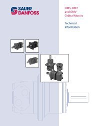
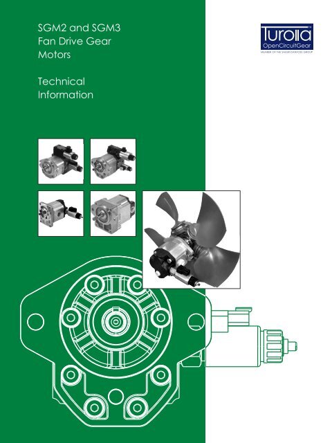
SGM2 and SGM3<br />
Fan Drive Gear<br />
Motors<br />
<br />
OpenCircuitGear<br />
ME<strong>MB</strong>ER OF THE SAUER-DANFOSS GROUP<br />
Technical<br />
Information
OpenCircuitGear<br />
<br />
ME<strong>MB</strong>ER OF THE SAUER-DANFOSS GROUP<br />
SGM2 and SGM3 Fan Drive Gear Motors<br />
Technical Information<br />
General Information<br />
History of revisions<br />
Table of revisions<br />
Date Page Changed Rev.<br />
28, June 2010 - First edition A<br />
Reference documents<br />
Literature reference for gear products<br />
System component Title Type and order number<br />
Cast Iron Hydraulic Gear Pumps Series D Technical Information 520L0781<br />
Pump<br />
Aluminium Gear Pumps Group 2<br />
Technical Information L1016341<br />
Aluminium Gear Pumps Group 3<br />
Technical Information L1016456<br />
Valve<br />
Proportional Solenoid Valves Tech Note 11022746<br />
Solenoid Valves Product Electrical Installation Tech Note 11022768<br />
Fan Drive Control Technical Information 11005336<br />
Fan drive control Fan Drive Control Temperature Sensors<br />
BLN-95-9063<br />
PLUS+1<br />
Datasheet 520L0719<br />
© 2010 <strong>Turolla</strong> OpenCircuitGear. All rights reserved.<br />
<strong>Turolla</strong> OCG accepts no responsibility for possible errors in catalogs, brochures and other printed material. <strong>Turolla</strong> OCG reserves<br />
the right to alter its products without prior notice. This also applies to products already ordered provided that such alterations<br />
can be made without affecting agreed specifi cations. All trademarks in this material are properties of their respective owners.<br />
Sauer-Danfoss, <strong>Turolla</strong>, <strong>Turolla</strong> OpenCircuitGear, <strong>Turolla</strong> OCG, OpenCircuitGear, Fast Lane and PLUS+1 are trademarks of the<br />
Sauer-Danfoss Group.<br />
2<br />
L1016036 • June 2010 • Rev A
OpenCircuitGear<br />
<br />
ME<strong>MB</strong>ER OF THE SAUER-DANFOSS GROUP<br />
SGM2 and SGM3 Fan Drive Gear Motors<br />
Technical Information<br />
Content<br />
General Information<br />
Overview........................................................................................................................................................... 5<br />
Features and benefits................................................................................................................................... 6<br />
Fan drive motor displacements................................................................................................................ 7<br />
Determination of nominal motor sizes.................................................................................................. 8<br />
Fan drive motor circuit illustrations........................................................................................................ 9<br />
System Requirements<br />
Pressure...........................................................................................................................................................10<br />
Speed...............................................................................................................................................................11<br />
Hydraulic fluids.............................................................................................................................................11<br />
Temperature and viscosity.......................................................................................................................12<br />
Filtration..........................................................................................................................................................<strong>13</strong><br />
Reservoir.........................................................................................................................................................<strong>13</strong><br />
Filters...........................................................................................................................................................<strong>13</strong><br />
Selecting a filter......................................................................................................................................<strong>13</strong><br />
Line sizing.......................................................................................................................................................14<br />
Motor shaft connection.............................................................................................................................14<br />
Motor life.........................................................................................................................................................14<br />
Group 2 Fan Drive<br />
Gear Motors – SGM2NC<br />
Motor design.................................................................................................................................................15<br />
Technical data...............................................................................................................................................15<br />
SGM2NC.....................................................................................................................................................15<br />
Model code....................................................................................................................................................16<br />
Mounting flange and shaft options......................................................................................................17<br />
SGM2NC • 02AA dimensions....................................................................................................................18<br />
SGM2NC • 06BA dimensions....................................................................................................................20<br />
SGM2NC • 06GB dimensions....................................................................................................................22<br />
Group 2 Fan Drive<br />
Gear Motors – SGM2YN<br />
Motor design.................................................................................................................................................24<br />
Technical data...............................................................................................................................................24<br />
SGM2YN.....................................................................................................................................................24<br />
Model code....................................................................................................................................................26<br />
Mounting flange and shaft options......................................................................................................29<br />
Outlet body ports configuration............................................................................................................30<br />
SGM2YN • 02AA dimensions....................................................................................................................32<br />
SGM2YN • 06BA dimensions....................................................................................................................34<br />
SGM2YN • 06GB dimensions....................................................................................................................36<br />
Group 2 Fan Drive<br />
Gear Motors – SGM2VC<br />
Group 2 Fan Drive<br />
Motor design.................................................................................................................................................38<br />
Technical data...............................................................................................................................................38<br />
SGM2VC.....................................................................................................................................................38<br />
Model code....................................................................................................................................................40<br />
Mounting flange and shaft options......................................................................................................42<br />
SGM2VC • 02AA dimensions....................................................................................................................44<br />
SGM2VC • 06BA dimensions....................................................................................................................46<br />
SGM2VC • 06GB dimensions....................................................................................................................48<br />
Outrigger bearing........................................................................................................................................50<br />
L1016036 • June 2010 • Rev A<br />
3
OpenCircuitGear<br />
<br />
ME<strong>MB</strong>ER OF THE SAUER-DANFOSS GROUP<br />
SGM2 and SGM3 Fan Drive Gear Motors<br />
Technical Information<br />
Content<br />
Gear Motors<br />
Group 3 Fan Drive<br />
Gear Motors – SGM3NC<br />
Motor design.................................................................................................................................................51<br />
Technical data...............................................................................................................................................51<br />
SGM3NC.....................................................................................................................................................51<br />
Model code....................................................................................................................................................52<br />
Mounting flange and shaft options......................................................................................................53<br />
SGM3NC • 07BC dimensions....................................................................................................................54<br />
SGM3NC • 07GB dimensions....................................................................................................................56<br />
Group 3 Fan Drive<br />
Gear Motors – SGM3YN<br />
Motor design.................................................................................................................................................58<br />
Technical data...............................................................................................................................................58<br />
SGM3YN.....................................................................................................................................................58<br />
Model code....................................................................................................................................................60<br />
Mounting flange and shaft options......................................................................................................62<br />
Outlet body port configuration..............................................................................................................62<br />
Outlet body port dimensions............................................................................................................63<br />
SGM3YN • 07BC dimensions....................................................................................................................64<br />
SGM3YN • 07GB dimensions....................................................................................................................66<br />
Group 3 Fan Drive<br />
Gear Motors – SGM3VC<br />
Motor design.................................................................................................................................................68<br />
Technical data...............................................................................................................................................68<br />
SGM3VC.....................................................................................................................................................68<br />
Model code....................................................................................................................................................70<br />
SGM3VC • 07BC dimensions.....................................................................................................................72<br />
SGM3VC • 07GB dimensions....................................................................................................................74<br />
Group 3 Fan Drive<br />
Gear Motors<br />
Outrigger bearing........................................................................................................................................76<br />
4<br />
L1016036 • June 2010 • Rev A
OpenCircuitGear<br />
<br />
ME<strong>MB</strong>ER OF THE SAUER-DANFOSS GROUP<br />
SGM2 and SGM3 Fan Drive Gear Motors<br />
Technical Information<br />
General Information<br />
Overview<br />
<strong>Turolla</strong> OCG has over many years built up a wealth of experience with its hydraulic and<br />
electro-hydraulic fan drive systems for vehicles and machines operating both on and<br />
off highway. Modern fan drives require proportional electronic control to meet new<br />
emissions legislation. SGM2 and SGM3 fan drive motors are based on the proven high<br />
performance <strong>Turolla</strong> OCG gear motors.<br />
A proportional pressure relief valve with pilot operated spool (normally closed) is<br />
integrated in the cast-iron rear cover of the motor. A gear pump supplies oil to the fan<br />
drive motor. The PWM signal to the solenoid pressure relief valve controls the oil flow<br />
through the motor which determines the fan speed. The fan speed is controlled to<br />
maintain optimum engine and hydraulic system temperatures. The SGM2YN, SGM3YN,<br />
SGM2VC and SGM3VC provide this proportional control in an integrated package within<br />
the rear cover.<br />
Bi-directional fan motor capability is necessary when it is desired to switch the rotation<br />
of the fan blade for such reasons as cleaning debris from a radiator. This allows for more<br />
efficient cooling of the machine engine and functions. The SGM2NC and SGM3NC<br />
provide the bidirectional capability for use with remote, inline mounted HIC manifolds<br />
that provide the reversing flow. The SGM2VC and the SGM3VC integrate the reversing<br />
valve capability in the rear cover of the motor.<br />
Due to the versatility, flexibility and reliability of <strong>Turolla</strong> OCG fan drive systems, they may<br />
be applied in numerous applications, such as:<br />
• Agriculture machinery<br />
• Construction machinery<br />
• Material handling vehicles<br />
• Road building vehicles<br />
• Forestry machinery<br />
• On-Highway vehicles<br />
L1016036 • June 2010 • Rev A<br />
5
OpenCircuitGear<br />
<br />
ME<strong>MB</strong>ER OF THE SAUER-DANFOSS GROUP<br />
SGM2 and SGM3 Fan Drive Gear Motors<br />
Technical Information<br />
General Information<br />
Features and benefits • Two groups of frame size (Group 2 and 3)<br />
• Steel and cast iron rear covers for 250 bar (3626 psi) continuous performance and<br />
270 bar [3916 psi] peak pressure for all port configurations<br />
• Displacement from 8 to 44 cm 3 /rev [from 0.51 to 2.69 in 3 /rev]<br />
• Maximum speed 3500 rpm for Group 2 and 2500 rpm for Group 3<br />
• Extreme temperature seals for continuous operation from -20 °C [-4 °F] up to +95 °C<br />
[+203 °F], for today's more demanding applications.<br />
• Two electro-hydraulic proportional valve options: PRV for standard fan speed<br />
modulation and optional flat curve valves for such applications as fan motors in<br />
series.<br />
• Deutch Electrical connectors as standard to withstand dust and debris in the<br />
enviroN•ment.<br />
• 12 V DC and 24 V DC coils.<br />
• Fail safe function - full fan speed if electrical signal fails.<br />
• Pressure settings factory pre-set for individual system performance.<br />
• High efficiency gear motors to reduce system losses and retain useful hydraulic<br />
power work functions<br />
• Outrigger bearings available for all 3 models to provide increased bearing capacity<br />
and therefore more durability or extended life in applications such as slewing,<br />
tracked machines, vibe and shock load applications that possess gyroscopic and<br />
impact loads or heavy steal fan blades.<br />
• Shaft seal dust protector standard on all models for extended seal life in fan drive<br />
applications<br />
• 2 Anti-Cavitation High Pressure Shock Valves, to clip pressure spikes in both<br />
directions of motor rotation, while reversing, where the competition uses only 1.<br />
• Integrated Reversing Directional Control Valves with open spool transitions to<br />
reduce system pressure spikes.<br />
• High performance valves and the use of steel / cast iron allows for full system<br />
pressure capability without de-rating the SGM product during reversing or<br />
proportional control.<br />
• Feature for Feature industry leading short package to preserve much needed engine<br />
space: integrated valves packages and factory sealed outrigger bearings with high<br />
speed capability,<br />
• PLUS+1 Compliant electronic interface allows for integration with PLUS+1<br />
microcontrollers and other compliant products including sensors and graphical<br />
displays.<br />
6<br />
L1016036 • June 2010 • Rev A
OpenCircuitGear<br />
<br />
ME<strong>MB</strong>ER OF THE SAUER-DANFOSS GROUP<br />
SGM2 and SGM3 Fan Drive Gear Motors<br />
Technical Information<br />
General Information<br />
Fan drive motor<br />
displacements<br />
Quick reference chart for fan drive motor models<br />
Rated pressure bar<br />
300<br />
250<br />
200<br />
150<br />
100<br />
50<br />
SGM2**<br />
SGM3**<br />
0<br />
0 5 10 15 20 25 30 35 40 45 50<br />
Displacement<br />
cm 3 /rev<br />
L1016036 • June 2010 • Rev A<br />
7
OpenCircuitGear<br />
<br />
ME<strong>MB</strong>ER OF THE SAUER-DANFOSS GROUP<br />
SGM2 and SGM3 Fan Drive Gear Motors<br />
Technical Information<br />
General Information<br />
Determination of<br />
nominal motor sizes<br />
Use these formulas to determine the nominal motor size for a specific application.<br />
Based on SI units<br />
Based on US units<br />
Input flow:<br />
V g • n<br />
Q = l/min<br />
1000 • η v<br />
V g • n<br />
Q = [US gal/min]<br />
231 • η v<br />
Output torque:<br />
M =<br />
V g • ∆p • η m<br />
20 • π<br />
N•m<br />
M =<br />
V g • ∆p • η m<br />
2 • π<br />
[lbf•in]<br />
Output power:<br />
P =<br />
M • n =<br />
Q • ∆p • η t kW<br />
9550 600<br />
P =<br />
M • n Q • ∆p • η = t [hp]<br />
63 025 1714<br />
Variables<br />
SI units [US units]<br />
V g<br />
= Displacement per revolution cm 3 /rev [in 3 /rev]<br />
p o<br />
= Outlet pressure bar [psi]<br />
p i<br />
= Inlet pressure bar [psi]<br />
∆p = p o<br />
– p i<br />
(system pressure) bar [psi]<br />
n = Speed min -1 (rpm)<br />
η v<br />
= Volumetric efficiency<br />
η m<br />
= Mechanical efficiency<br />
η t<br />
= Overall efficiency (η v<br />
• η m<br />
)<br />
8<br />
L1016036 • June 2010 • Rev A
OpenCircuitGear<br />
<br />
ME<strong>MB</strong>ER OF THE SAUER-DANFOSS GROUP<br />
SGM2 and SGM3 Fan Drive Gear Motors<br />
Technical Information<br />
General Information<br />
Fan drive motor circuit<br />
illustrations<br />
Gear pump/gear motor with HIC electrical control<br />
CAN Bus<br />
Microcontroller<br />
(PLUS+1 TM )<br />
Reversing<br />
Switch<br />
Reservoir<br />
Filter<br />
Engine Control<br />
Module (ECM)<br />
T1<br />
Diesel Engine<br />
Fan Drive Gear<br />
Motor (SGM3)<br />
T2<br />
Gear pump<br />
(Series D)<br />
T3<br />
Reversing and Modulating<br />
Fan Drive HIC<br />
Temperature<br />
Sensors<br />
(T1, T2, T3)<br />
Gear pump/gear motor with electro-proportional relief valve<br />
CAN Bus<br />
Reservoir<br />
Filter<br />
Microcontroller<br />
(PLUS+1 TM )<br />
T1<br />
Temperature<br />
sensors<br />
Diesel engine<br />
T2<br />
Gear pump<br />
(SNP)<br />
Fan drive<br />
gear motor<br />
T3<br />
Gear pump/gear motor with integrated reversing control valve<br />
CAN Bus<br />
Microcontroller<br />
(PLUS+1 TM )<br />
Reservoir<br />
Filter<br />
Engine Control<br />
Module (ECM)<br />
Diesel Engine<br />
Gear Pump<br />
(D Series)<br />
Case Drain<br />
T1<br />
T2<br />
Temperature<br />
Sensors<br />
T1, T2, T3<br />
SGM2VC Aluminum<br />
Fan Drive Motor with<br />
Integrated Reversing<br />
Valves<br />
T3<br />
L1016036 • June 2010 • Rev A<br />
9
OpenCircuitGear<br />
<br />
ME<strong>MB</strong>ER OF THE SAUER-DANFOSS GROUP<br />
SGM2 and SGM3 Fan Drive Gear Motors<br />
Technical Information<br />
System Requirements<br />
Pressure<br />
Peak pressure is the highest<br />
intermittent pressure allowed.<br />
The relief valve overshoot (reaction time)<br />
determines peak pressure. It is assumed<br />
to occur for less than 100 ms.<br />
The illustration to the right shows peak<br />
pressure in relation to rated pressure and<br />
reaction time (100 ms maximum).<br />
Time versus pressure<br />
Pressure<br />
Peak pressure<br />
Rated pressure<br />
Rated pressure is the average, regularly<br />
occurring operating inlet pressure that<br />
should yield satisfactory product life.<br />
The maximum machine load at the<br />
motor shaft determines rated pressure.<br />
Reaction time (100 ms max)<br />
Time<br />
System pressure is the differential between the inlet and outlet ports. It is a dominant<br />
operating variable affecting hydraulic unit life. High system pressure, resulting from high<br />
load at the motor shaft, reduces expected life. System pressure must remain at, or below,<br />
rated pressure during normal operation to achieve expected life.<br />
Back pressure is the average, regularly occurring operating outlet pressure that should<br />
yield satisfactory motor life. The hydraulic load demand downstream of the motor<br />
determines the back pressure. The fan drive gear motor can work with back pressure and<br />
the maximum back pressure allowed is 60% of the maximum rated pressure.<br />
Case drain pressure is the regularly occurring case drain line pressure that should yield<br />
satisfactory motor life. It is recommended to design the case drain piping connecting the<br />
case drain direct to the tank in order to keep the case drain pressure as low as possible.<br />
Max. continuous case drain pressure allowed is 5 bar [72.5 psi] with a peak of 7 bar<br />
[101.5 psi].<br />
10<br />
L1016036 • June 2010 • Rev A
OpenCircuitGear<br />
<br />
ME<strong>MB</strong>ER OF THE SAUER-DANFOSS GROUP<br />
SGM2 and SGM3 Fan Drive Gear Motors<br />
Technical Information<br />
System Requirements<br />
Speed<br />
Maximum speed is the limit recommended by <strong>Turolla</strong> OCG for a particular gear motor<br />
when operating at rated pressure. It is the highest speed at which normal life can be<br />
expected. N2 is max speed related to the RV valve setting ( p2) and type of fan.<br />
The lower limit of operating speed is the minimum speed. It is the lowest speed at low<br />
pressure.<br />
The minimum speed increases as operating system pressure increases. When operating<br />
under higher pressures, a higher minimum speed must be maintained, as illustrated to<br />
the right.<br />
Speed versus pressure<br />
Example of typical fan loading curve<br />
P 2<br />
Rated<br />
Pressure<br />
Start-up<br />
area<br />
Operating<br />
envelope<br />
P 1<br />
0 N<br />
1<br />
Speed<br />
N<br />
N<br />
2 max<br />
Hydraulic fluids<br />
Ratings and data for gear motors are based on operating with premium hydraulic fluids<br />
containing oxidation, rust, and foam inhibitors. These fluids must possess good thermal<br />
and hydrolytic stability to prevent wear, erosion, and corrosion of internal components.<br />
Please see <strong>Turolla</strong> OCG publication Hydraulic Fluids and Lubricants Technical<br />
Information, 520L0463 for more information. Refer to publication Experience with<br />
Biodegradable Hydraulic Fluids Technical Information, 520L0465 for information<br />
relating to biodegradable fluids.<br />
Use only clean fluid in the motor and hydraulic circuit.<br />
CCaution<br />
Never mix hydraulic fluids.<br />
L1016036 • June 2010 • Rev A<br />
11
OpenCircuitGear<br />
<br />
ME<strong>MB</strong>ER OF THE SAUER-DANFOSS GROUP<br />
SGM2 and SGM3 Fan Drive Gear Motors<br />
Technical Information<br />
System Requirements<br />
Temperature and<br />
viscosity<br />
Temperature and viscosity requirements must be concurrently satisfied.<br />
Use petroleum/mineral-based fluids.<br />
Temperature<br />
High temperature limits apply at the inlet port of the motor. The motor should run at or<br />
below the maximum continuous temperature.<br />
Cold oil, generally, doesn’t affect the durability of motor components. It may affect the<br />
ability of oil to flow and transmit power. For this reason, keep the temperature at 16°C<br />
[60 °F] above the pour point of the hydraulic fluid.<br />
Minimum (cold start) temperature<br />
relates to the physical properties of<br />
component materials.<br />
Maximum continuous temperature<br />
allowed at which normal life can be<br />
expected.<br />
Temperature<br />
Minimum (cold start)<br />
-20 [-4]<br />
Maximum<br />
°C 95 [203]<br />
continuous<br />
[°F]<br />
Peak (intermittent) 110 [230]<br />
Peak (intermittent) temperature: the overheating temperature that is tolerable by the<br />
machine for a transient/limited time.<br />
Viscosity<br />
Minimum viscosity occurs only during brief occasions of maximum ambient<br />
temperature and severe duty cycle operation. It’s the minimum acceptable viscosity to<br />
allow normal motor life.<br />
Maximum viscosity occurs only during cold start at very low ambient temperatures. It’s<br />
the upper limit of viscosity that allows the motor to start.<br />
Fluid viscosity<br />
Maximum (cold start)<br />
1600 [7273]<br />
Recommended range 12–100 [66–456]<br />
Minimum<br />
mm 2 /s<br />
[SUS]<br />
10 [60]<br />
Recommended range for high<br />
efficiency<br />
20–50 [97–231]<br />
12<br />
L1016036 • June 2010 • Rev A
OpenCircuitGear<br />
<br />
ME<strong>MB</strong>ER OF THE SAUER-DANFOSS GROUP<br />
SGM2 and SGM3 Fan Drive Gear Motors<br />
Technical Information<br />
System Requirements<br />
Filtration<br />
Filters<br />
Use a filter that conforms to Class 22/18/<strong>13</strong> of ISO 4406 (or better).<br />
It may be on the motor outlet (discharge filtration) or inlet (pressure filtration).<br />
Selecting a filter<br />
When selecting a filter, please consider:<br />
• contaminant ingression rate (determined by factors such as the number of actuators<br />
used in the system)<br />
• generation of contaminants in the system<br />
• required fluid cleanliness<br />
• desired maintenance interval<br />
• filtration requirements of other system components<br />
Measure filter efficiency with a Beta ratio (β X<br />
):<br />
• for discharge filtration with controlled reservoir ingression, use a β 35-45<br />
= 75 filter<br />
• for pressure filtration, use a filtration with an efficiency of β 10<br />
= 75<br />
βx ratio is a measure of filter efficiency defined by ISO 4572. It is the ratio of the number of particles greater<br />
than a given diameter ( “X“ in microns) upstream of the filter to the number of these particles downstream of<br />
the filter.<br />
Fluid cleanliness level and β x<br />
ratio<br />
Fluid cleanliness level (per ISO 4406) Class 22/18/<strong>13</strong> or better<br />
β x<br />
ratio (discharge filtration) β 35-45<br />
= 75 and β 10<br />
= 2<br />
β x<br />
ratio (pressure filtration) β 10<br />
= 75<br />
Recommended inlet screen size<br />
100 – 125 µm [0.0039 – 0.0049 in]<br />
The filtration requirements for each system are unique. Evaluate filtration system capacity<br />
by monitoring and testing prototypes.<br />
Reservoir<br />
The reservoir provides clean fluid, dissipates heat, removes entrained air, and allows for<br />
fluid volume changes associated with fluid expansion and during all system operating<br />
modes. A correctly sized reservoir accommodates maximum volume changes during all<br />
system operating modes. It promotes de-aeration of the fluid as it passes through, and<br />
accommodates a fluid dwell-time between 60 and 180 seconds, allowing entrained air to<br />
escape.<br />
Minimum reservoir capacity depends on the volume required to cool and hold the<br />
oil, allowing for expansion due to temperature changes. A fluid volume of one to three<br />
times the motor output flow (per minute) is satisfactory. The minimum recommended<br />
reservoir capacity is 125% of the fluid volume.<br />
Put the return-line below the lowest expected fluid level to allow discharge into the<br />
reservoir for maximum dwell and efficient de-aeration. A baffle (or baffles) between the<br />
return and suction lines promotes de-aeration and reduces fluid surges.<br />
L1016036 • June 2010 • Rev A<br />
<strong>13</strong>
OpenCircuitGear<br />
<br />
ME<strong>MB</strong>ER OF THE SAUER-DANFOSS GROUP<br />
SGM2 and SGM3 Fan Drive Gear Motors<br />
Technical Information<br />
System Requirements<br />
Line sizing<br />
Choose pipe sizes that accommodate minimum fluid velocity to reduce system noise,<br />
pressure drops and overheating in order to maximize system life and performance. Line<br />
velocity should not exceed 5.0 m/s [16.4 ft/s]:<br />
Most systems use hydraulic oil containing 10% dissolved air by volume. Over-aeration,<br />
or entrained air, is the result of flow line restrictions, where the dissolved air comes<br />
out of solution, or when air is allowed to leak into the hydraulic circuit. These include<br />
inadequate pipe sizes, sharp bends, or elbow fittings, causing a reduction of flow-line<br />
cross-sectional area. This problem will not occur if these circuit recommendations are<br />
followed, rated speed requirements are maintained, and reservoir size and location are<br />
adequate.<br />
Motor shaft connection<br />
Shaft options for fan drive gear motors include tapered (1:5 and 1:8) and parallel.<br />
Allowable radial shaft loads are a function of the load position, load orientation, and<br />
operating pressure of the hydraulic motor. All external shaft loads have an effect on<br />
bearing life, and may affect motor performance.<br />
In applications where the external shaft loads cannot be avoided, minimize the impact<br />
on the motor by optimizing the orientation and the magnitude of the load. <strong>Turolla</strong> OCG<br />
fan drive gear motors are capable of carryng most manufaturer's plastic fans up to 7.27<br />
kg (16 lb) fan blades for the Group 2 and 11.75 kg (26 lb) fan blades for the Group 3.<br />
For fan drives exceeding these loads, with presence of shock loads, or for slewing (swing)<br />
and oscilating applications such as Excavators, Wheel<br />
Loaders, Harvester, and Windrowers, please consult your<br />
<strong>Turolla</strong> OCG Technical Representative for the potential usage<br />
of an outrigger bearing.<br />
See following drawing for fan drive mounting orientation to<br />
be considered.<br />
Motor life is a function of speed, system pressure, and other<br />
Motor life<br />
system parameters (such as fluid quality and cleanliness).<br />
All <strong>Turolla</strong> OCG gear motors use hydrodynamic journal bearings that have an oil film<br />
maintained between the gear/shaft and bearing surfaces at all times. If the oil film<br />
is sufficiently sustained through proper system maintenance and operating within<br />
recommended limits, long life can be expected.<br />
B 10<br />
life expectancy number is generally associated with rolling element<br />
bearings. It does not exist for hydrodynamic bearings.<br />
High pressure impacts motor life. When submitting an application for review, provide<br />
machine duty cycle data that includes percentages of time at various loads and speeds.<br />
We strongly recommend a prototype testing program to verify operating parameters<br />
and their impact on life expectancy before finalizing any system design.<br />
14<br />
L1016036 • June 2010 • Rev A
OpenCircuitGear<br />
<br />
ME<strong>MB</strong>ER OF THE SAUER-DANFOSS GROUP<br />
SGM2 and SGM3 Fan Drive Gear Motors<br />
Technical Information<br />
SGM2NC – Group 2 Fan Drive Gear Motors<br />
Motor design<br />
SGM2NC<br />
SGM2NC is Group 2 bidirectional fan drive motor with<br />
inlet/outlet on cast iron rear cover and axial drain line<br />
Displacement range from 8.4 cm 3 /rev up to 25.2 cm 3 /rev<br />
[from 0.51 up to 1.54 in 3 /rev].<br />
Configurations include European and SAE flanges; taper<br />
1:8, taper 1:5 and parallel Ø15.875 mm [Dia 0,62 in]<br />
shafts.<br />
Outrigger bearing available as SAE A flange with taper<br />
shaft 1:8 and European flange with taper shaft 1:5.<br />
SGM2NC<br />
Technical data<br />
Technical data for SGM2NC standard fan drive gear motors<br />
Frame size 8,0 011 014 017 019 022 025<br />
Displacement<br />
Peak pressure<br />
Rated pressure<br />
Back pressure<br />
cm 3 /rev<br />
[in 3 /rev]<br />
bar<br />
[psi]<br />
8.4<br />
[0.51]<br />
270<br />
[3916]<br />
250<br />
[3626]<br />
250<br />
[3626]<br />
10.8<br />
[0.66]<br />
270<br />
[3916]<br />
250<br />
[3626]<br />
250<br />
[3626]<br />
14.4<br />
[0.88]<br />
270<br />
[3916]<br />
250<br />
[3626]<br />
250<br />
[3626]<br />
16.8<br />
[1.03]<br />
250<br />
[3626]<br />
230<br />
[3336]<br />
230<br />
[3336]<br />
19.2<br />
[1.17]<br />
230<br />
[3336]<br />
210<br />
[3046]<br />
210<br />
[3046]<br />
22.8<br />
[1.39]<br />
200<br />
[2900]<br />
180<br />
[2610]<br />
180<br />
[2610]<br />
25.2<br />
[1.54]<br />
180<br />
[2610]<br />
Maximum speed<br />
3500 3500 3500 3500 3200 3200 3200<br />
min -1 (rpm)<br />
Minimum speed 700 700 700 500 500 500 500<br />
160<br />
[2320]<br />
160<br />
[2320]<br />
Weight<br />
Moment of inertia of<br />
rotating components<br />
kg<br />
[lb]<br />
x 10 -6 kg•m 2<br />
[x 10 -6 lbf•ft 2 ]<br />
3.2<br />
[7.05]<br />
32.4<br />
[769]<br />
3.75<br />
[8.26]<br />
38.4<br />
[911]<br />
3.9<br />
[8.60]<br />
47.3<br />
[1122]<br />
4.05<br />
[8.93]<br />
53.3<br />
[1265]<br />
4.15<br />
[9.15]<br />
59.2<br />
[1405]<br />
4.3<br />
[9.48]<br />
68.1<br />
[1616]<br />
4.4<br />
[9.70]<br />
74.1<br />
[1758]<br />
L1016036 • June 2010 • Rev A<br />
15
OpenCircuitGear<br />
<br />
ME<strong>MB</strong>ER OF THE SAUER-DANFOSS GROUP<br />
SGM2 and SGM3 Fan Drive Gear Motors<br />
Technical Information<br />
SGM2NC – Group 2 Fan Drive Gear Motors<br />
Model code A B C D E F G H I J K L M N<br />
S G M 2 N C / B A N N N N N N N N / N N N<br />
A<br />
Type<br />
SGM2NC<br />
Group 2 fan drive motor with cast iron rear cover, with inlet/outlet port 7∕8–14UNF–2B,<br />
standard drain (radial position)<br />
B<br />
Displacement<br />
C<br />
Sense of rotation<br />
8,0 8.4 cm 3 /rev [0.51 in 3 /rev]<br />
011 10.8 cm 3 /rev [0.66 in 3 /rev]<br />
014 14.4 cm 3 /rev [0.88 in 3 /rev]<br />
017 16.8 cm 3 /rev [1.02 in 3 /rev]<br />
019 19.2 cm 3 /rev [1.12 in 3 /rev]<br />
022 22.8 cm 3 /rev [1.39 in 3 /rev]<br />
025 25.2 cm 3 /rev [1.54 in 3 /rev]<br />
D<br />
B<br />
Version<br />
A<br />
Bidirectional<br />
High temperature sealing<br />
Dust protector<br />
Rust protected screws<br />
E<br />
02AA<br />
Mounting flange and shaft<br />
European 02 flange, pilot Ø 80 mm<br />
[Dia 3.15 in] 4-bolts - 1:5 Tapered shaft,<br />
Key 3 – M12 x 1.25<br />
06BA<br />
SAE A flange, pilot Ø 82.55 [Dia 3.25 in]<br />
2-bolts - 1:8 Tapered shaft,<br />
Key 4 – M12 x 1.25<br />
06GB<br />
SAE A flange, pilot Ø 82.55 mm [Dia 3.25<br />
in] 2-bolts- Ø 15.875 mm [Dia 0.625 in]<br />
Parallel shaft L=50.8 mm [2 in] thd hole<br />
M6 Key 4x40 mm [1.57 in]<br />
9YDB<br />
Outrigger Bearing with dust cover -<br />
SAE A flange pilot Ø 82,55 [Dia 3.25 in]<br />
2-bolts - 1:8 Tapered shaft,<br />
Key 4 – M12 x 1.25<br />
F<br />
C5<br />
Rear cover<br />
Cast Iron cover with 7/8 14 UNF-2B<br />
In-Out Ports - 9/16-18 UNF 2B Axial Drain<br />
(idler gear side)<br />
CX<br />
Cast Iron cover with 7/8 14 UNF-2B<br />
In-Out Ports - 9/16-18 UNF 2B Radial<br />
Drain (idler gear side)<br />
G<br />
Inlet body port<br />
H<br />
Outlet body port<br />
NN<br />
No inlet on body<br />
NN<br />
No outlet on body<br />
16<br />
L1016036 • June 2010 • Rev A
OpenCircuitGear<br />
<br />
ME<strong>MB</strong>ER OF THE SAUER-DANFOSS GROUP<br />
SGM2 and SGM3 Fan Drive Gear Motors<br />
Technical Information<br />
SGM2NC – Group 2 Fan Drive Gear Motors<br />
Model code<br />
(continued)<br />
A B C D E F G H I J K L M N<br />
S G M 2 N C / B A N N N N N N N N / N N N<br />
I Outlet port position, variant body<br />
NN Standard<br />
J Sealing<br />
N Standard high temperature seals<br />
M<br />
Marking<br />
N Standard marking<br />
A Standard + customer code<br />
Z Without marking<br />
* Special customer marking<br />
K<br />
L<br />
Screws<br />
N<br />
Valve<br />
NNN<br />
Standard zinc plated screws<br />
No valve<br />
N<br />
Mark position<br />
N Standard marking position<br />
A Idler gear side<br />
Mounting flange and<br />
shaft options<br />
<strong>Turolla</strong> OCG offers two types of industry standard mounting flanges. The table below<br />
shows order codes for each available mounting flange and its intended use:<br />
A B C D E F G H I J K L M N<br />
S G M 2 N C / B A N N N N N N N N / N N N<br />
Shaft/Flange<br />
Maximum torque<br />
Code Description Code 02 flange Code 06 flange<br />
02AA<br />
06BA<br />
06GB<br />
European, pilot Ø 80 mm [Dia 3.15 in], 4-bolts<br />
Taper 1:5, Key 3 – M12 x 1.25<br />
SAE A, pilot Ø 82.55 mm [Dia 3.25 in], 2-bolts<br />
Taper 1:8, Key 4 – M12 x 1.25<br />
SAE A, pilot Ø 82.55 mm [Dia 3.25 in], 2-bolts<br />
Parallel Ø 15.875 [Dia 0.625], L 50.8 [2]<br />
140 N•m<br />
[1239 lb•in]<br />
–<br />
–<br />
–<br />
150 N•m<br />
[<strong>13</strong>28 lb•in]<br />
80 N•m<br />
[708 lb•in]<br />
Spline configuration is not available for Group 2 fan drive motors. Other shaft options<br />
may exist. Contact your <strong>Turolla</strong> OCG representative for availability.<br />
CCaution<br />
Shaft torque capability may limit allowable pressure. Torque ratings assume<br />
no external radial loading. Applied torque must not exceed these limits,<br />
regardless of stated pressure parameters. Maximum torque ratings are<br />
based on shaft torsional fatigue strength.<br />
L1016036 • June 2010 • Rev A<br />
17
OpenCircuitGear<br />
<br />
ME<strong>MB</strong>ER OF THE SAUER-DANFOSS GROUP<br />
SGM2 and SGM3 Fan Drive Gear Motors<br />
Technical Information<br />
SGM2NC – Group 2 Fan Drive Gear Motors<br />
SGM2NC • 02AA dimensions<br />
B +1.5 [+0.059] max<br />
A<br />
±1.0 [±0.04]<br />
92 max<br />
[3.622 max.]<br />
72<br />
[2.83]<br />
mm<br />
[in]<br />
15.7 ±0.5<br />
[0.62 ±0.02 ]<br />
120 [4.72] max.<br />
(100 [3.94])<br />
65.5<br />
34.5<br />
[2.59]<br />
[1.36]<br />
Inlet/Outlet: 7/8–14UNF–2B<br />
(SAE J1926/1 O-Ring boss)<br />
16.7 [0.66] min. full thread<br />
9 +0.5<br />
0<br />
+0.02<br />
[0.35 0 ]<br />
Ø 0.75<br />
X<br />
A ±1[±0.04]<br />
12.5 ±1<br />
[ 0.49 ±0.039]<br />
7.2 ±0.25<br />
[0.28 ±0.01]<br />
36.2 max.<br />
[1.425 max.]<br />
89 max<br />
[3.504 max.]<br />
-0.06<br />
-0.106<br />
Ø 80<br />
-0.002<br />
[Ø3.15 -0.004 ]<br />
X<br />
R 0.8 max.<br />
[0.03 max.]<br />
15.7 ±0.5<br />
[0.62 ±0.02 ]<br />
67.6 max.<br />
[2.66 max.]<br />
26 ±1<br />
[1.02 ±0.04 ]<br />
103 [4.055] max.<br />
Inlet/Outlet: 7/8–14UNF–2B<br />
(SAE J1926/1 O-Ring boss)<br />
16.7 [0.66] min. full thread<br />
Drain: 9/16–18UNF–2B<br />
(SAE J1926/1 O-Ring boss)<br />
12.7 [0.5] min. full thread<br />
18<br />
L1016036 • June 2010 • Rev A
OpenCircuitGear<br />
<br />
ME<strong>MB</strong>ER OF THE SAUER-DANFOSS GROUP<br />
SGM2 and SGM3 Fan Drive Gear Motors<br />
Technical Information<br />
SGM2NC – Group 2 Fan Drive Gear Motors<br />
SGM2NC • 02AA<br />
dimensions (continued)<br />
<strong>13</strong> ±0.5<br />
[0.51 ±0.02]<br />
M12x1.25-6g<br />
11.5 [0.453] min.<br />
full thread<br />
(19.3)<br />
([0.76])<br />
A<br />
38 ±1<br />
[1.5 ±0.04]<br />
5.7 ±0.75<br />
[0.22 ±0.029]<br />
16.5 ±0.75<br />
[0.65 ±0.029]<br />
P<br />
D<br />
Detail ‘D’<br />
mm<br />
[in]<br />
Ø 34 [Dia 1.34]<br />
Depth 2.4 [0.09] max<br />
Inlet/Outlet<br />
39.5 ±0.25<br />
[1.555 ±0.01]<br />
Ø 17.46<br />
[Dia 0.687]<br />
Ø 0.35<br />
A<br />
1: 5<br />
X<br />
9 +0.3<br />
-0.1<br />
+0.012<br />
-0.004<br />
[0.354 ]<br />
A-A<br />
90 ±0.25<br />
[3.54 ±0.01]<br />
Detail ‘P’<br />
3.7 max<br />
[0.14 max]<br />
3 0<br />
-0.025<br />
0<br />
-0.001<br />
[0.118 ]<br />
SGM2NC – 02AA dimensions<br />
Frame size 8,0 011 014 017 019 022 025<br />
A<br />
B<br />
Inlet/Outlet<br />
Drain port<br />
98<br />
[3.86]<br />
118.5<br />
[4.66]<br />
102<br />
[4.01]<br />
122.5<br />
[4.83]<br />
108<br />
[4.25]<br />
128.5<br />
[5.05]<br />
112<br />
[4.41]<br />
<strong>13</strong>2.5<br />
[5.22]<br />
116<br />
[4.57]<br />
<strong>13</strong>6.5<br />
[5.37]<br />
7/8–14UNF–2B (SAE J1926/1 O-Ring boss); 16.7 [0.66] min. full thread<br />
9/16–18UNF–2B (SAE J1926/1 O-Ring boss); 12.7 [0.5] min. full thread<br />
Model code example and maximum shaft torque<br />
122<br />
[4.80]<br />
142.5<br />
[5.61]<br />
126<br />
[4.96]<br />
146.5<br />
[5.77]<br />
Flange/shaft Model code example Maximum shaft torque<br />
02AA SGM2NC/011BA02AAC5NNNNNNNN/NNNNN 140 N•m [1239 lb•in]<br />
For further details on ordering, see Model Code, page 16 and 17.<br />
L1016036 • June 2010 • Rev A<br />
19
X<br />
OpenCircuitGear<br />
<br />
ME<strong>MB</strong>ER OF THE SAUER-DANFOSS GROUP<br />
SGM2 and SGM3 Fan Drive Gear Motors<br />
Technical Information<br />
SGM2NC – Group 2 Fan Drive Gear Motors<br />
SGM2NC • 06BA dimensions<br />
A<br />
±1 [±0.04]<br />
12 ±1<br />
[ 0.47 ±0.04]<br />
0<br />
6.35 -0.5<br />
[0.25 0<br />
-0.02 ]<br />
<strong>13</strong>2 max<br />
[5.2 max.]<br />
106.38<br />
[4.19]<br />
mm<br />
[in]<br />
R 48 max.<br />
[1.89] max.<br />
X<br />
R 0.8 max.<br />
[0.03 max.]<br />
B +1.5 [+0.06] max.<br />
A<br />
±1.0 [±0.04]<br />
89 max<br />
[3.504 max.]<br />
15.7 ±0.5<br />
[0.62 ±0.02 ]<br />
26 ±1<br />
[1.02 ±0.04 ]<br />
15.7 ±0.5<br />
[0.62 ±0.02 ]<br />
19.5 max.<br />
[0.77] max.<br />
115.5 max.<br />
[4.55] max.<br />
R 12.7 max.<br />
[0.5] max.<br />
11–11.6<br />
[0.43–0.46]<br />
Ø 0.75<br />
36.2 max.<br />
[1.43] max.<br />
67.6 max.<br />
[2.66] max.<br />
103 max.<br />
[4.055] max.<br />
0<br />
Ø 82.55 +0.05<br />
0<br />
[Ø3.25 +0.002 ]<br />
Inlet/Outlet: 7/8–14UNF–2B<br />
(SAE J1926/1 O-Ring boss)<br />
16.7 [0.66] min. full thread<br />
Inlet/Outlet: 7/8–14UNF–2B<br />
(SAE J1926/1 O-Ring boss)<br />
16.7 [0.66] min. full thread<br />
Drain: 9/16–18UNF–2B<br />
(SAE J1926/1 O-Ring boss)<br />
12.7 [0.5] min. full thread<br />
20<br />
L1016036 • June 2010 • Rev A
OpenCircuitGear<br />
<br />
ME<strong>MB</strong>ER OF THE SAUER-DANFOSS GROUP<br />
SGM2 and SGM3 Fan Drive Gear Motors<br />
Technical Information<br />
SGM2NC – Group 2 Fan Drive Gear Motors<br />
SGM2NC • 06BA<br />
dimensions (continued)<br />
12.5 ±0.5<br />
[0.49 ±0.02]<br />
M12x1.25-6g<br />
11 [0.433] min.<br />
full thread<br />
(21.7)<br />
([0.85])<br />
40.5 ±1<br />
[1.59 ±0.04]<br />
Detail ‘P’<br />
6.3 ±0.75<br />
[0.25 ±0.029]<br />
17 ±0.75<br />
[0.67 ±0.029]<br />
P<br />
D<br />
5.7 max.<br />
[0.22 max.]<br />
mm<br />
[in]<br />
A<br />
Ø 17.46<br />
[Dia 0.687 ]<br />
Ø 0.35<br />
A<br />
1: 8<br />
X<br />
9.5 +0.15<br />
-0.25<br />
+0.006<br />
-0.0098<br />
[0.37 ]<br />
A-A<br />
90 ±0.25<br />
[3.54 ±0.01]<br />
Detail ‘D’<br />
Ø 34 [Dia 1.34]<br />
Depth 2.4 [0.39] max<br />
Inlet/Outlet<br />
0<br />
4 -0.03<br />
0<br />
[0.16 ]<br />
-0.0012<br />
39.5 ±0.25<br />
[1.56 ±0.01]<br />
SGM2NC – 06BA dimensions<br />
Frame size 8,0 011 014 017 019 022 025<br />
A<br />
B<br />
Inlet/Outlet<br />
Drain port<br />
95.5<br />
[3.76]<br />
116<br />
[4.57]<br />
99.5<br />
[3.92]<br />
120<br />
[4.72]<br />
105.5<br />
[4.15]<br />
126<br />
[4.96]<br />
109.5<br />
[4.31]<br />
<strong>13</strong>0<br />
[5.11]<br />
1<strong>13</strong>.5<br />
[4.47]<br />
<strong>13</strong>4<br />
[5.28]<br />
7/8–14UNF–2B (SAE J1926/1 O-Ring boss); 16.7 [0.66] min. full thread<br />
9/16–18UNF–2B (SAE J1926/1 O-Ring boss); 12.7 [0.5] min. full thread<br />
119.5<br />
[4.70]<br />
140<br />
[5.51]<br />
123.5<br />
[4.86]<br />
144<br />
[5.67]<br />
Model code example and maximum shaft torque<br />
Flange/shaft Model code example Maximum shaft torque<br />
06BA SGM2NC/011BA06BAC5NNNNNNNN/NNNNN 150 N•m [<strong>13</strong>28 lb•in]<br />
For further details on ordering, see Model Code, page 16 and 17.<br />
L1016036 • June 2010 • Rev A<br />
21
X<br />
OpenCircuitGear<br />
<br />
ME<strong>MB</strong>ER OF THE SAUER-DANFOSS GROUP<br />
SGM2 and SGM3 Fan Drive Gear Motors<br />
Technical Information<br />
SGM2NC – Group 2 Fan Drive Gear Motors<br />
SGM2NC • 06GB dimensions<br />
A<br />
±1 [±0.04]<br />
12 ±1<br />
[ 0.47 ±0.04]<br />
0<br />
6.35 -0.5<br />
[0.25 0<br />
-0.02 ]<br />
<strong>13</strong>2 max<br />
[5.2 max.]<br />
106.38<br />
[4.19]<br />
mm<br />
[in]<br />
R 48 max.<br />
[1.89] max.<br />
X<br />
R 0.8 max.<br />
[0.03 max.]<br />
B +1.5 [+0.06] max.<br />
A<br />
±1.0 [±0.04]<br />
89 max<br />
[3.504 max.]<br />
15.7 ±0.5<br />
[0.62 ±0.02 ]<br />
26 ±1<br />
[1.02 ±0.04 ]<br />
19.5 max.<br />
[0.77] max.<br />
115.5 max.<br />
[4.55] max.<br />
15.7 ±0.5<br />
[0.62 ±0.02 ]<br />
R 12.7 max.<br />
[0.5] max.<br />
11–11.6<br />
[0.43–0.46]<br />
Ø 0.75<br />
36.2 max.<br />
[1.43] max.<br />
67.6 max.<br />
[2.66] max.<br />
103 max.<br />
[4.055] max.<br />
0<br />
Ø 82.55 +0.05<br />
0<br />
[Ø3.25 +0.002 ]<br />
Inlet/Outlet: 7/8–14UNF–2B<br />
(SAE J1926/1 O-Ring boss)<br />
16.7 [0.66] min. full thread<br />
Inlet/Outlet: 7/8–14UNF–2B<br />
(SAE J1926/1 O-Ring boss)<br />
16.7 [0.66] min. full thread<br />
Drain: 9/16–18UNF–2B<br />
(SAE J1926/1 O-Ring boss)<br />
12.7 [0.5] min. full thread<br />
22<br />
L1016036 • June 2010 • Rev A
OpenCircuitGear<br />
<br />
ME<strong>MB</strong>ER OF THE SAUER-DANFOSS GROUP<br />
SGM2 and SGM3 Fan Drive Gear Motors<br />
Technical Information<br />
SGM2NC – Group 2 Fan Drive Gear Motors<br />
SGM2NC • 06GB<br />
dimensions (continued)<br />
58.0 ±1<br />
[2.31 ±0.04]<br />
50.8 ±0.25<br />
[2.0 ±0.01]<br />
7.9 ±0.75<br />
[0.51 ±0.029]<br />
D<br />
mm<br />
[in]<br />
0<br />
-0.25<br />
Ø 15.875<br />
[Dia 0.625 -0.01 ]<br />
0<br />
A<br />
B<br />
B<br />
90 ±0.25<br />
[3.54 ±0.01 ]<br />
Ø 0.1 / 25.4<br />
K<br />
A<br />
M6 - 6H<br />
Ø 0.35 X<br />
B-B<br />
A-A<br />
17.475–17.729<br />
[0.688–0.698]<br />
Detail ‘D’<br />
Ø 34 [Dia 1.34]<br />
Depth 2.4 [0.39] max.<br />
Inlet/Outlet<br />
16 min.<br />
[0.63 min.]<br />
0<br />
4 -0.03<br />
0<br />
[0.16 -0.001]<br />
39.5 ±0.25<br />
[0.62 ±0.01 ]<br />
SGM2NC – 06GB dimensions<br />
Frame size 8,0 011 014 017 019 022 025<br />
A<br />
B<br />
Inlet/Outlet<br />
Drain port<br />
95.5<br />
[3.76]<br />
116<br />
[4.57]<br />
99.5<br />
[3.92]<br />
120<br />
[4.72]<br />
105.5<br />
[4.15]<br />
126<br />
[4.96]<br />
109.5<br />
[4.31]<br />
<strong>13</strong>0<br />
[5.11]<br />
1<strong>13</strong>.5<br />
[4.47]<br />
<strong>13</strong>4<br />
[5.28]<br />
7/8–14UNF–2B (SAE J1926/1 O-Ring boss); 16.7 [0.66] min. full thread<br />
9/16–18UNF–2B (SAE J1926/1 O-Ring boss); 12.7 [0.5] min. full thread<br />
119.5<br />
[4.70]<br />
140<br />
[5.51]<br />
123.5<br />
[4.86]<br />
144<br />
[5.67]<br />
Model code example and maximum shaft torque<br />
Flange/shaft Model code example Maximum shaft torque<br />
06GB SGM2NC/011BA06GBC5NNNNNNNN/NNNNN 80 N•m [708 lb•in]<br />
For further details on ordering, see Model Code, page 16 and 17.<br />
L1016036 • June 2010 • Rev A<br />
23
OpenCircuitGear<br />
<br />
ME<strong>MB</strong>ER OF THE SAUER-DANFOSS GROUP<br />
SGM2 and SGM3 Fan Drive Gear Motors<br />
Technical Information<br />
Group 2 Fan Drive Gear Motors – SGM2YN<br />
Motor design<br />
SGM2YN<br />
SGM2YN is Group 2 fan drive motor with inlet<br />
on rear cover and outlet on body.Integrated<br />
proportional relief valve, anti-cavitation check<br />
valve and axial drain line.<br />
Displacement range from 8.4 cm 3 /rev up to<br />
25.2 cm 3 /rev [from 0.51 up to 1.54 in 3 /rev].<br />
Configurations include European and SAE<br />
flanges; taper 1:8, taper 1:5 and parallel<br />
Ø15.875 mm [Dia 0,62 in] shafts.<br />
Outrigger bearing available as SAE A flange<br />
with taper shaft 1:8 and European flange with<br />
taper shaft 1:5.<br />
SGM2YN<br />
Technical data<br />
Technical data for SGM2YN standard fan drive gear motors<br />
Frame size 8,0 011 014 017 019 022 025<br />
Displacement<br />
Peak pressure<br />
Rated pressure<br />
Back pressure<br />
cm 3 /rev<br />
[in 3 /rev]<br />
bar<br />
[psi]<br />
8.4<br />
[0.51]<br />
270<br />
[3916]<br />
250<br />
[3626]<br />
150<br />
[2176]<br />
10.8<br />
[0.66]<br />
270<br />
[3916]<br />
250<br />
[3626]<br />
150<br />
[2176]<br />
14.4<br />
[0.88]<br />
270<br />
[3916]<br />
250<br />
[3626]<br />
150<br />
[2176]<br />
16.8<br />
[1.03]<br />
250<br />
[3626]<br />
230<br />
[3336]<br />
150<br />
[2176]<br />
19.2<br />
[1.17]<br />
230<br />
[3336]<br />
210<br />
[3046]<br />
<strong>13</strong>0<br />
[1885]<br />
22.8<br />
[1.39]<br />
200<br />
[2900]<br />
180<br />
[2610]<br />
100<br />
[1450]<br />
25.2<br />
[1.54]<br />
180<br />
[2610]<br />
Maximum speed<br />
3500 3500 3500 3500 3200 3200 3200<br />
min -1 (rpm)<br />
Minimum speed 700 700 700 500 500 500 500<br />
160<br />
[2320]<br />
100<br />
[1450]<br />
Weight<br />
Moment of inertia of<br />
rotating components<br />
kg<br />
[lb]<br />
x 10 -6 kg•m 2<br />
[x 10 -6 lbf•ft 2 ]<br />
4.73<br />
[10.43]<br />
32.4<br />
[769]<br />
4.83<br />
[10.65]<br />
38.4<br />
[911]<br />
5.03<br />
[11.1]<br />
47.3<br />
[1122]<br />
5.18<br />
[11.42]<br />
53.3<br />
[1265]<br />
5.23<br />
[11.53]<br />
59.2<br />
[1405]<br />
5.33<br />
[11.75]<br />
68.1<br />
[1616]<br />
5.53<br />
[12.2]<br />
74.1<br />
[1758]<br />
24<br />
L1016036 • June 2010 • Rev A
OpenCircuitGear<br />
<br />
ME<strong>MB</strong>ER OF THE SAUER-DANFOSS GROUP<br />
SGM2 and SGM3 Fan Drive Gear Motors<br />
Technical Information<br />
SGM2YN – Group 2 Fan Drive Gear Motors<br />
Technical data<br />
(continued)<br />
Electro proportional relief valve standard<br />
156 [6.14] max<br />
Electrical connectors Deutsch DT 04-2P connectors (Protection rate IP 69K DIN 40050)<br />
Electrical supply to EH valve<br />
0 to 1.1 A @ 12 V DC, with coil resistance of 7.2 Ω @ 20 °C [68 °F]<br />
0 to 0.55 A @ 24 V DC, with coil resistance of 28.8 Ω @ 20 °C [68 °F]<br />
PWM frequency<br />
from 100 to 200 Hz<br />
Electro proportional relief valve flat curve<br />
168 [6.61] max<br />
Electrical connectors Deutsch DT 04-2P connectors (Protection rate IP 69K DIN 40050)<br />
Electrical supply to EH valve<br />
0 to 1.1 A @ 12 V DC, with coil resistance of 6.4 Ω @ 20 °C [68 °F]<br />
0 to 0.55 A @ 24 V DC, with coil resistance of 26.2 Ω @ 20 °C [68 °F]<br />
PWM frequency<br />
from 100 to 250 Hz<br />
L1016036 • June 2010 • Rev A<br />
25
OpenCircuitGear<br />
<br />
ME<strong>MB</strong>ER OF THE SAUER-DANFOSS GROUP<br />
SGM2 and SGM3 Fan Drive Gear Motors<br />
Technical Information<br />
SGM2YN – Group 2 Fan Drive Gear Motors<br />
Model code A B C D E F G H I J K L M N<br />
S G M 2 Y * / A N N N N /<br />
A Type<br />
SGM2YN<br />
SGM2YL<br />
Gr2 Fan Drive Motor with EH Proportional Pressure Control;<br />
Cast Iron cover-Inlet port 7/8-14 UNF on Cover-Axial Drain Line<br />
Gr2 Fan Drive Motor with EH Proportional Pressure Control;<br />
Cast Iron cover-Inlet port 7/8-14 UNF on Cover-Radial Drain Line<br />
B<br />
Displacement<br />
8,0 8.4 cm 3 /rev [0.51 in 3 /rev]<br />
011 10.8 cm 3 /rev [0.66 in 3 /rev]<br />
014 14.4 cm 3 /rev [0.88 in 3 /rev]<br />
017 16.8 cm 3 /rev [1.02 in 3 /rev]<br />
019 19.2 cm 3 /rev [1.12 in 3 /rev]<br />
022 22.8 cm 3 /rev [1.39 in 3 /rev]<br />
025 25.2 cm 3 /rev [1.54 in 3 /rev]<br />
C<br />
D<br />
Sense of rotation<br />
R<br />
L<br />
Version<br />
A<br />
Right (clockwise)<br />
Left (counterclockwise)<br />
High-Temperature sealing<br />
Dust protector<br />
Galvanized screws<br />
E<br />
02AA<br />
Mounting flange and shaft<br />
European 02 flange, pilot Ø 80 mm<br />
[Dia 3.15 in] 4-bolts - 1:5 Tapered shaft,<br />
Key 3 – M12 x 1.25<br />
06BA<br />
SAE A flange, pilot Ø 82.55 [Dia 3.25 in]<br />
2-bolts - 1:8 Tapered shaft,<br />
Key 4 – M12 x 1.25<br />
06GB<br />
SAE A flange, pilot Ø 82.55 mm [Dia 3.25<br />
in] 2-bolts- Ø 15.875 mm [Dia 0.625 in]<br />
Parallel shaft L=50.8 mm [2 in] thd hole<br />
M6 Key 4x40 mm [1.57 in]<br />
9YDB<br />
Outrigger Bearing with dust cover -<br />
SAE A flange pilot Ø 82,55 [Dia 3.25 in]<br />
2-bolts - 1:8 Tapered shaft,<br />
Key 4 – M12 x 1.25<br />
F Rear cover<br />
Cast Iron cover with 7/8 14 UNF-2B In<br />
Y6 Port - 9/16-18 UNF 2B Axial Drain<br />
(idler gear side)<br />
Y4<br />
Cast Iron cover with 7/8 14 UNF-2B In<br />
Port - 9/16-18 UNF 2B Radial Drain<br />
(idler gear side)<br />
26<br />
L1016036 • June 2010 • Rev A
OpenCircuitGear<br />
<br />
ME<strong>MB</strong>ER OF THE SAUER-DANFOSS GROUP<br />
SGM2 and SGM3 Fan Drive Gear Motors<br />
Technical Information<br />
SGM2YN – Group 2 Fan Drive Gear Motors<br />
Model code<br />
(continued)<br />
A B C D E F G H I J K L M N<br />
S G M 2 Y * / A N N N N /<br />
G<br />
H<br />
Inlet body port<br />
NN<br />
No inlet in body<br />
Outlet body port<br />
B5 15 x 35 x M6 Flanged port, 4-threaded holes in x pattern,<br />
B7 20 x 40 x M6 (German standard)<br />
C3 <strong>13</strong>.5 x 30 x M6<br />
Flanged port, 4-threaded holes in + pattern,<br />
C7 20 x 40 x M8<br />
(European standard)<br />
C8 23.5 x 40 x M8<br />
D7 M22 x 1.5<br />
D9 M26 x 1.5<br />
Threaded metric<br />
E5 7/ 8 –14UNF<br />
E6 1–1/ ₁ ₆ –12UN<br />
Threaded SAE, O-ring boss<br />
F4 ½ GAS<br />
F5 ¾ GAS<br />
Threaded GAS (BSPP)<br />
I<br />
Outlet port position and variant body<br />
NN Standard motor - No outlet in body<br />
YY B5 or B7 with SAE-A flange off-set to rear cover<br />
ZZ B5 or B7 in the center of the body<br />
J<br />
K<br />
Sealing<br />
N<br />
Screws<br />
N<br />
Std High Temperature Seals<br />
Std Zinc Plated Screws<br />
L1016036 • June 2010 • Rev A<br />
27
OpenCircuitGear<br />
<br />
ME<strong>MB</strong>ER OF THE SAUER-DANFOSS GROUP<br />
SGM2 and SGM3 Fan Drive Gear Motors<br />
Technical Information<br />
SGM2YN – Group 2 Fan Drive Gear Motors<br />
Model code<br />
(continued)<br />
A B C D E F G H I J K L M N<br />
S G M 2 Y * / A N N N N /<br />
L<br />
XNN<br />
XA*<br />
XB*<br />
Valve set<br />
No valve<br />
Standard relief valve with coil voltage 12 V DC, DT connector<br />
Standard relief valve with coil voltage 24 V DC, DT connector<br />
X*F Select Pressure vs. Bypass flow requirements using the graph below. Three color curves<br />
represent three types of valves. Each valve is characterized by different nominal spring<br />
ranges.<br />
X*I<br />
X*M<br />
X*O<br />
X*Q<br />
X*S<br />
X*U<br />
X*W<br />
X*Y<br />
Pressure<br />
∆<br />
psi bar<br />
4000<br />
300<br />
3000<br />
2000<br />
1000<br />
250<br />
200<br />
150<br />
100<br />
50<br />
Y<br />
W<br />
U<br />
SQO<br />
M<br />
I<br />
F<br />
0<br />
0<br />
0<br />
20<br />
40<br />
60<br />
80 l/min<br />
0 4 8 12 16 20 US gal/min<br />
Bypass flow<br />
SA*<br />
SB*<br />
Flat curve valve with coil voltage 12 V DC, DT connector<br />
Flat curve valve with coil voltage 24 V DC, DT connector<br />
S*O<br />
S*S<br />
S*W<br />
S*X<br />
S*W<br />
S*X<br />
WCaution<br />
Maximum pressure setting will vary depending on pressure vs. bypass flow<br />
requirements.<br />
M<br />
Marking<br />
N Standard marking<br />
A Standard + customer code<br />
Z Without marking<br />
* Special customer marking<br />
N<br />
Mark position<br />
N Standard marking position<br />
A Idler gear side<br />
28<br />
L1016036 • June 2010 • Rev A
OpenCircuitGear<br />
<br />
ME<strong>MB</strong>ER OF THE SAUER-DANFOSS GROUP<br />
SGM2 and SGM3 Fan Drive Gear Motors<br />
Technical Information<br />
SGM2YN – Group 2 Fan Drive Gear Motors<br />
Mounting flange and<br />
shaft options<br />
<strong>Turolla</strong> OCG offers two types of industry standard mounting flanges. The table below<br />
shows order codes for each available mounting flange and its intended use:<br />
A B C D E F G H I J K L M N<br />
S G M 2 Y * / A N N N N /<br />
Shaft/Flange<br />
Maximum torque<br />
Code Description Code 02 flange Code 06 flange<br />
02AA<br />
06BA<br />
06GB<br />
European, pilot Ø 80 mm [Dia 3.15 in], 4-bolts<br />
Taper 1:5, Key 3 – M12 x 1.25<br />
SAE A, pilot Ø 82.55 mm [Dia 3.25 in], 2-bolts<br />
Taper 1:8, Key 4 – M12 x 1.25<br />
SAE A, pilot Ø 82.55 mm [Dia 3.25 in], 2-bolts<br />
Parallel Ø 15.875 [Dia 0.625], L 50.8 [2]<br />
140 N•m<br />
[1239 lb•in]<br />
–<br />
–<br />
–<br />
150 N•m<br />
[<strong>13</strong>28 lb•in]<br />
80 N•m<br />
[708 lb•in]<br />
Spline configuration is not available for Group 2 fan drive motors. Other shaft options<br />
may exist. Contact your <strong>Turolla</strong> OCG representative for availability.<br />
CCaution<br />
Shaft torque capability may limit allowable pressure. Torque ratings assume<br />
no external radial loading. Applied torque must not exceed these limits,<br />
regardless of stated pressure parameters. Maximum torque ratings are<br />
based on shaft torsional fatigue strength.<br />
L1016036 • June 2010 • Rev A<br />
29
OpenCircuitGear<br />
<br />
ME<strong>MB</strong>ER OF THE SAUER-DANFOSS GROUP<br />
SGM2 and SGM3 Fan Drive Gear Motors<br />
Technical Information<br />
SGM2YN – Group 2 Fan Drive Gear Motors<br />
Outlet body ports<br />
configuration<br />
<strong>Turolla</strong> OCG offers two types of industry standard mounting flanges. The table below<br />
shows order codes for each available outlet body ports and its intended use:<br />
Standard port configurations availability<br />
A B C D E F G H I J K L M N<br />
S G M 2 Y * / A N N N N /<br />
Code Outlet body description Standard on<br />
flange/shaft<br />
Inlet/Outlet<br />
port design<br />
B5<br />
B7<br />
C3<br />
C7<br />
C8<br />
Flanged 15 x 35 x M6 in × pattern (German standard<br />
ports)<br />
Flanged 20 x 40 x M6 in × pattern (German standard<br />
ports)<br />
Flanged 15 x 30 x M6 in + pattern (European<br />
standard ports)<br />
Flanged 20 x 40 x M8 in + pattern (European<br />
standard ports)<br />
Flanged 23 x 40 x M8 in + pattern (European<br />
standard ports)<br />
02AA<br />
Non-standard<br />
D7 Threaded metric M22 x 1.5<br />
Non-standard<br />
D9 Threaded metric M26 x 1.5<br />
E5<br />
E6<br />
SAE, O-ring boss 7/ 8 –14UNF<br />
SAE, O-ring boss 1–1/ ₁ ₆ –12UN<br />
06BA<br />
06GB<br />
9YDB<br />
F4<br />
F5<br />
Threaded ½ GAS (BSPP)<br />
Threaded ¾ GAS (BSPP)<br />
Non-standard<br />
30<br />
L1016036 • June 2010 • Rev A
OpenCircuitGear<br />
<br />
ME<strong>MB</strong>ER OF THE SAUER-DANFOSS GROUP<br />
SGM2 and SGM3 Fan Drive Gear Motors<br />
Technical Information<br />
SGM2YN – Group 2 Fan Drive Gear Motors<br />
Outlet body port<br />
dimension<br />
Available ports for Group 2 fan drive motors<br />
B*<br />
C*<br />
D* E*<br />
F*<br />
45 o<br />
g<br />
h<br />
x<br />
y<br />
d<br />
e<br />
f<br />
i (4 holes min. full thd.<br />
12 mm [0.47 in] deep)<br />
z (4 holes min. full thd.<br />
12 mm [0.47 in] deep)<br />
Group 2 fan drive motors ports dimensions (standard)<br />
Standard outlet body port<br />
B*<br />
for 02AA flange/shaft code<br />
E*<br />
for 06BA, 06GB flange/shaft code<br />
Port dimensions<br />
g h i e<br />
8,0<br />
B5 15 [0.591] 35 [1.378]<br />
E5<br />
7/8–14 UNF<br />
011 B5 15 [0.591] 35 [1.378] E5 7/8–14 UNF<br />
014 B5 15 [0.591] 35 [1.378] E5 7/8–14 UNF<br />
017 B5 15 [0.591] 35 [1.378] M6 E5 7/8–14 UNF<br />
019 B7 20 [0.787] 40 [1.575] E6 1–1/16–12 UN<br />
022 B7 20 [0.787] 40 [1.575] E6 1–1/16–12 UN<br />
025 B7 20 [0.787] 40 [1.575] E6 1–1/16–12 UN<br />
Frame size<br />
Outlet port options<br />
Outlet port options<br />
Group 2 fan drive motors ports dimensions (non-standard)<br />
Non-standard outlet port<br />
C* D* F*<br />
Port dimensions<br />
x y z d f<br />
8,0<br />
C3 <strong>13</strong>.5 [0.531] 30 [1.181] M6 D7 M22x1.5<br />
F4 ½ Gas (BSPP)<br />
011 C3 <strong>13</strong>.5 [0.531] 30 [1.181] M6 D7 M22x1.5 F4 ½ Gas (BSPP)<br />
014 C7 20 [0.787] 40 [1.575] M8 D7 M22x1.5 F4 ½ Gas (BSPP)<br />
017 C7 20 [0.787] 40 [1.575] M8 D7 M22x1.5 F4 ½ Gas (BSPP)<br />
019 C7 20 [0.787] 40 [1.575] M8 D9 M26x1.5 F5 ¾ Gas (BSPP)<br />
022 C7 20 [0.787] 40 [1.575] M8 D9 M26x1.5 F5 ¾ Gas (BSPP)<br />
025 C8 23.5 [0.925] 40 [1.575] M8 D9 M26x1.5 F5 ¾ Gas (BSPP)<br />
Frame size<br />
Outlet port options<br />
Outlet port options<br />
Outlet port options<br />
L1016036 • June 2010 • Rev A<br />
31
OpenCircuitGear<br />
<br />
ME<strong>MB</strong>ER OF THE SAUER-DANFOSS GROUP<br />
SGM2 and SGM3 Fan Drive Gear Motors<br />
Technical Information<br />
SGM2YN – Group 2 Fan Drive Gear Motors<br />
SGM2YN • 02AA dimensions<br />
mm<br />
[in]<br />
C +1.5 [+0.059] max<br />
B<br />
±1[±0.04]<br />
92 max<br />
[3.622 max.]<br />
72<br />
[2.83]<br />
156 max<br />
[6.142 max.]<br />
15.7 ±0.5<br />
[0.62 ±0.02 ]<br />
120 [4.72] max.<br />
(100 [3.94])<br />
65.5<br />
34.5<br />
[2.59]<br />
[1.36]<br />
Inlet D<br />
9 +0.5<br />
0<br />
+0.02<br />
[0.35 0 ]<br />
Ø 0.75<br />
X<br />
12.5 ±1<br />
[ 0.49 ±0.039]<br />
7.2 ±0.25<br />
[0.28 ±0.01]<br />
B ±1[±0.04]<br />
A<br />
±0.5 [±0.02]<br />
G M6-6H<br />
12 [0.47] min.<br />
full thread<br />
36.2 max.<br />
[1.425 max.]<br />
Connector: Deutsch DT 04-2P<br />
Voltage: 12V DC (Current 1.1 A)<br />
24V DC (Current 0.55 A)<br />
PWM 100-200 Hz<br />
89 max<br />
[3.504 max.]<br />
-0.06<br />
-0.106<br />
Ø 80<br />
-0.002<br />
[Ø3.15 -0.004 ]<br />
X<br />
R 0.8 max.<br />
[0.03 max.]<br />
Outlet<br />
45 o<br />
E +0.5 0<br />
F<br />
[<br />
+0.02<br />
0 ]<br />
±0.2 [±0.008]<br />
15.7 ±0.5<br />
[0.62 ±0.02 ]<br />
67.6 max.<br />
[2.66 max.]<br />
Valve type: PRV10–IS2<br />
Drain: 9/16–18UNF–2B<br />
(SAE J1926/1 O-Ring boss)<br />
12.7 [0.5] min. full thread<br />
26 ±1<br />
[1.02 ±0.04 ]<br />
103 [4.055] max.<br />
Dr<br />
32<br />
L1016036 • June 2010 • Rev A
OpenCircuitGear<br />
<br />
ME<strong>MB</strong>ER OF THE SAUER-DANFOSS GROUP<br />
SGM2 and SGM3 Fan Drive Gear Motors<br />
Technical Information<br />
SGM2YN – Group 2 Fan Drive Gear Motors<br />
SGM2YN • 02AA<br />
dimensions (continued)<br />
<strong>13</strong> ±0.5<br />
[0.51 ±0.02]<br />
38 ±1<br />
[1.5 ±0.04]<br />
Detail ‘P’<br />
mm<br />
[in]<br />
M12x1.25-6g<br />
11.5 [0.453] min.<br />
full thread<br />
(19.3)<br />
([0.76])<br />
5.7 ±0.75<br />
[0.22 ±0.029]<br />
16.5 ±0.75<br />
[0.65 ±0.029]<br />
P<br />
H<br />
3.7 max<br />
[0.14 max]<br />
Ø 17.46<br />
[Dia 0.687]<br />
Ø 0.35<br />
9 +0.3<br />
-0.1<br />
+0.012<br />
-0.004<br />
[0.354 ]<br />
A<br />
A<br />
1: 5<br />
X<br />
A-A<br />
90 ±0.25<br />
[3.54 ±0.01]<br />
Detail ‘H’<br />
Ø 34 [Dia 1.34]<br />
Depth 5 [0.2] max<br />
Inlet D<br />
(SAE J1926/1 O-Ring boss)<br />
16.7 [0.66] min. full thread<br />
3 0<br />
-0.025<br />
0<br />
-0.001<br />
[0.118 ]<br />
39.5 ±0.25<br />
[1.555 ±0.01]<br />
SGM2YN – 02AA dimensions<br />
Frame size 8,0 011 014 017 019 022 025<br />
A 43.1 [1.70] 47.5 [1.87] 47.5 [1.87] 47.5 [1.87] 47.5 [1.87] 55.0 [2.17] 64.5 [2.54]<br />
B 98 [3.86] 102 [4.01] 108 [4.25] 112 [4.41] 116 [4.57] 122 [4.80] 126 [4.96]<br />
Dimension<br />
118.5 122.5 128.5 <strong>13</strong>2.5 <strong>13</strong>6.5 142.5 146.5<br />
C<br />
[4.66] [4.83] [5.05] [5.22] [5.37] [5.61] [5.77]<br />
Inlet D 7/8–14UNF–2B (SAE J1926/1 O-Ring boss); 16.7 [0.66] min. full thread<br />
E 15 [0.59] 20 [0.79]<br />
Outlet<br />
F 35 [0.38] 40 [0.57]<br />
G<br />
M6–6H; 12 [0.47] min. full thread<br />
Drain port<br />
9/16–18UNF–2B (SAE J1926/1 O-Ring boss); 12.7 [0.5] min. full thread<br />
Inlet is always the same.<br />
Model code example and maximum shaft torque<br />
Flange/shaft Model code example Maximum shaft torque<br />
02AA SGM2YN/014LA02AAY6NNE5NNNN/XNNNN 140 N•m [1239 lb•in]<br />
For further details on ordering, see Model Code, pages 26 - 28.<br />
L1016036 • June 2010 • Rev A<br />
33
X<br />
OpenCircuitGear<br />
<br />
ME<strong>MB</strong>ER OF THE SAUER-DANFOSS GROUP<br />
SGM2 and SGM3 Fan Drive Gear Motors<br />
Technical Information<br />
SGM2YN – Group 2 Fan Drive Gear Motors<br />
SGM2YN • 06BA dimensions<br />
B<br />
±1 [±0.04]<br />
12 ±1<br />
[ 0.47 ±0.04]<br />
0<br />
6.35 -0.5<br />
[0.25 0<br />
-0.02 ]<br />
X<br />
R 48 max.<br />
[1.89] max.<br />
<strong>13</strong>2 max<br />
[5.2 max.]<br />
106.38<br />
[4.19]<br />
156 max<br />
[6.142 max.]<br />
mm<br />
[in]<br />
R 12.7 max.<br />
[0.5] max.<br />
15.7 ±0.5<br />
[0.62 ±0.02 ]<br />
0<br />
Ø 82.55 +0.05<br />
0<br />
[Ø3.25 +0.002 ]<br />
19.5 max.<br />
[0.77] max.<br />
115.5 max.<br />
[4.55] max.<br />
Inlet D<br />
R 0.8 max.<br />
[0.03 max.]<br />
11–11.6<br />
[0.43–0.46]<br />
Ø 0.75<br />
C +1.5 [+0.06] max.<br />
A<br />
±0.5 [±0.02]<br />
36.2 max.<br />
[1.43] max.<br />
Connector: Deutsch DT 04-2P<br />
Voltage: 12V DC (Current: 1.1 A)<br />
24V DC (Current: 0.55 A)<br />
PWM: 100–200 Hz<br />
89 max<br />
[3.504 max.]<br />
15.7 ±0.5<br />
[0.62 ±0.02 ]<br />
67.6 max.<br />
[2.66] max.<br />
Valve Type: PRV10-IS2<br />
26 ±1<br />
[1.02 ±0.04 ]<br />
103 max.<br />
[4.055] max.<br />
Outlet E<br />
(SAE J1926/1 O-Ring boss)<br />
F min. full thread<br />
Drain: 9/16–18UNF–2B<br />
(SAE J1926/1 O-Ring boss)<br />
12.7 [0.5] min. full thread<br />
Dr<br />
34<br />
L1016036 • June 2010 • Rev A
OpenCircuitGear<br />
<br />
ME<strong>MB</strong>ER OF THE SAUER-DANFOSS GROUP<br />
SGM2 and SGM3 Fan Drive Gear Motors<br />
Technical Information<br />
SGM2YN – Group 2 Fan Drive Gear Motors<br />
SGM2YN • 06BA<br />
dimensions (continued)<br />
12.5 ±0.5<br />
[0.49 ±0.02]<br />
M12x1.25-6g<br />
11 [0.433] min.<br />
full thread<br />
(19.3)<br />
([0.76])<br />
40.5 ±1<br />
[1.59 ±0.04]<br />
6.3 ±0.75<br />
[0.25 ±0.029]<br />
17 ±0.75<br />
[0.67 ±0.029]<br />
P<br />
H<br />
5.7 max.<br />
[0.22 max.]<br />
Detail ‘P’<br />
mm<br />
[in]<br />
A<br />
Ø 17.46<br />
[Dia 0.687 ]<br />
Ø 0.35<br />
A<br />
1: 8<br />
X<br />
90 ±0.25<br />
[3.54 ±0.01]<br />
Detail ‘H’<br />
Ø 34 [Dia 1.34]<br />
Depth 5 [0.2] max<br />
9.5 +0.15<br />
-0.25<br />
+0.006<br />
-0.0098<br />
[0.37 ]<br />
A-A<br />
Inlet D<br />
(SAE J1926/1 O-Ring boss)<br />
16.7 [0.66] min. full thread<br />
SGM2YN – 06BA dimensions<br />
Frame size 8,0 011 014 017 019 022 025<br />
Dimension<br />
A<br />
B<br />
C<br />
4 -0.03<br />
0<br />
[0.16 ]<br />
47<br />
[1.85]<br />
95.5<br />
[3.76]<br />
116<br />
[4.57]<br />
49<br />
[1.93]<br />
99.5<br />
[3.92]<br />
120<br />
[4.72]<br />
52<br />
[2.05]<br />
105.5<br />
[4.15]<br />
126<br />
[4.96]<br />
54<br />
[2.<strong>13</strong>]<br />
109.5<br />
[4.31]<br />
<strong>13</strong>0<br />
[5.11]<br />
56<br />
[2.21]<br />
1<strong>13</strong>.5<br />
[4.47]<br />
<strong>13</strong>4<br />
[5.28]<br />
59<br />
[2.32]<br />
119.5<br />
[4.70]<br />
140<br />
[5.51]<br />
Inlet D 7/8–14UNF–2B (SAE J1926/1 O-Ring boss); 16.7 [0.66] min. full thread<br />
Outlet<br />
E 7/8–14UNF–2B 1–1/16–12UN–2B<br />
F 16.7 [0.66] min. full thread 19 [0.75] min. full thread<br />
Drain port<br />
9/16–18UNF–2B (SAE J1926/1 O-Ring boss); 12.7 [0.5] min. full thread<br />
Inlet is always the same.<br />
0<br />
-0.0012<br />
39.5 ±0.25<br />
[1.56 ±0.01]<br />
61<br />
[2.40]<br />
123.5<br />
[4.86]<br />
144<br />
[5.67]<br />
Model code example and maximum shaft torque<br />
Flange/shaft Model code example Maximum shaft torque<br />
06BA SGM2YN/025RA06BAY6NNE6NNNN/XNNNN 150 N•m [<strong>13</strong>28 lb•in]<br />
For further details on ordering, see Model Code, pages 26 - 28.<br />
L1016036 • June 2010 • Rev A<br />
35
X<br />
OpenCircuitGear<br />
<br />
ME<strong>MB</strong>ER OF THE SAUER-DANFOSS GROUP<br />
SGM2 and SGM3 Fan Drive Gear Motors<br />
Technical Information<br />
SGM2YN – Group 2 Fan Drive Gear Motors<br />
SGM2YN • 06GB dimensions<br />
B<br />
±1 [±0.04]<br />
12 ±1<br />
[ 0.47 ±0.04]<br />
0<br />
6.35 -0.5<br />
[0.25 0<br />
-0.02 ]<br />
X<br />
R 48 max.<br />
[1.89] max.<br />
<strong>13</strong>2 max<br />
[5.2 max.]<br />
106.38<br />
[4.19]<br />
156 max<br />
[6.142 max.]<br />
mm<br />
[in]<br />
15.7 ±0.5<br />
[0.62 ±0.02 ]<br />
0<br />
Ø 82.55 +0.05<br />
0<br />
[Ø3.25 +0.002 ]<br />
19.5 max.<br />
[0.77] max.<br />
115.5 max.<br />
[4.55] max.<br />
R 12.7 max.<br />
[0.5] max.<br />
Inlet D<br />
R 0.8 max.<br />
[0.03 max.]<br />
11–11.6<br />
[0.43–0.46]<br />
Ø 0.75<br />
C +1.5 [+0.06] max.<br />
A<br />
±0.5 [±0.02]<br />
36.2 max.<br />
[1.43] max.<br />
Connector: Deutsch DT 04-2P<br />
Voltage: 12V DC (Current: 1.1 A)<br />
24V DC (Current: 0.55 A)<br />
PWM: 100–200 Hz<br />
89 max<br />
[3.504 max.]<br />
15.7 ±0.5<br />
[0.62 ±0.02 ]<br />
67.6 max.<br />
[2.66] max.<br />
Valve Type: PRV10-IS2<br />
26 ±1<br />
[1.02 ±0.04 ]<br />
103 max.<br />
[4.055] max.<br />
Outlet E<br />
(SAE J1926/1 O-Ring boss)<br />
F min. full thread<br />
Drain: 9/16–18UNF–2B<br />
(SAE J1926/1 O-Ring boss)<br />
12.7 [0.5] min. full thread<br />
Dr<br />
36<br />
L1016036 • June 2010 • Rev A
OpenCircuitGear<br />
<br />
ME<strong>MB</strong>ER OF THE SAUER-DANFOSS GROUP<br />
SGM2 and SGM3 Fan Drive Gear Motors<br />
Technical Information<br />
SGM2YN – Group 2 Fan Drive Gear Motors<br />
SGM2YN • 06GB<br />
dimensions (continued)<br />
58.0 ±1<br />
[2.31 ±0.04]<br />
mm<br />
[in]<br />
0<br />
-0.25<br />
Ø 15.875<br />
[Dia 0.625 -0.01 ]<br />
0<br />
50.8 ±0.25<br />
[2.0 ±0.01]<br />
P<br />
A<br />
7.9 ±0.75<br />
[0.51 ±0.029]<br />
Detail ‘P’<br />
5.7 max.<br />
[0.224 max.]<br />
Ø 0.1 / 25.4<br />
K<br />
B<br />
A<br />
B<br />
Ø 0.35 X<br />
M6 - 6H<br />
B-B<br />
A-A<br />
17.475–17.729<br />
[0.688–0.698]<br />
16 min.<br />
[0.63 min.]<br />
0<br />
4 -0.03<br />
0<br />
[0.16 -0.001]<br />
SGM2YN – 06GB dimensions<br />
Frame size 8,0 011 014 017 019 022 025<br />
Dimension<br />
A<br />
B<br />
C<br />
47<br />
[1.85]<br />
95.5<br />
[3.76]<br />
116<br />
[4.57]<br />
49<br />
[1.93]<br />
99.5<br />
[3.92]<br />
120<br />
[4.72]<br />
52<br />
[2.05]<br />
105.5<br />
[4.15]<br />
126<br />
[4.96]<br />
54<br />
[2.<strong>13</strong>]<br />
109.5<br />
[4.31]<br />
<strong>13</strong>0<br />
[5.11]<br />
56<br />
[2.21]<br />
1<strong>13</strong>.5<br />
[4.47]<br />
<strong>13</strong>4<br />
[5.28]<br />
59<br />
[2.32]<br />
119.5<br />
[4.70]<br />
140<br />
[5.51]<br />
Inlet D 7/8–14UNF–2B (SAE J1926/1 O-Ring boss); 16.7 [0.66] min. full thread<br />
Outlet<br />
E 7/8–14UNF–2B 1–1/16–12UN–2B<br />
F 16.7 [0.66] min. full thread 19 [0.75] min. full thread<br />
Drain port<br />
9/16–18UNF–2B (SAE J1926/1 O-Ring boss); 12.7 [0.5] min. full thread<br />
Inlet is always the same.<br />
Model code example and maximum shaft torque<br />
61<br />
[2.40]<br />
123.5<br />
[4.86]<br />
144<br />
[5.67]<br />
Flange/shaft Model code example Maximum shaft torque<br />
06GB SGM2YN/022L406GBY6NNE6NNNN/XNNNN 80 N•m [708 lb•in]<br />
For further details on ordering, see Model Code, pages 26 - 28.<br />
L1016036 • June 2010 • Rev A<br />
37
OpenCircuitGear<br />
<br />
ME<strong>MB</strong>ER OF THE SAUER-DANFOSS GROUP<br />
SGM2 and SGM3 Fan Drive Gear Motors<br />
Technical Information<br />
Group 2 Fan Drive Gear Motors – SGM2VC<br />
Motor design<br />
SGM2VC<br />
SGM2VC is Group 2 fan drive motor<br />
with integrated DCV valve for “reverse<br />
function”, anti-shock and proportional<br />
relief valve. Inlet/outlet and radial drain<br />
line are on cast iron rear cover.<br />
Displacement range from 8.4 cm 3 /rev up<br />
to 25.2 cm 3 /rev [from 0.51 up to 1.54 in 3 /<br />
rev].<br />
Configurations include European and<br />
SAE flanges; taper 1:8, taper 1:5 and<br />
parallel Ø15.875 mm [Dia 0,62 in] shafts.<br />
Outrigger bearing available as SAE A<br />
flange with taper shaft 1:8 and European<br />
flange with taper shaft 1:5.<br />
SGM2VC<br />
Technical data<br />
Technical data for SGM2VC standard fan drive gear motors<br />
Frame size 8,0 011 014 017 019 022 025<br />
Displacement<br />
Peak pressure<br />
Rated pressure<br />
Back pressure<br />
cm 3 /rev<br />
[in 3 /rev]<br />
bar<br />
[psi]<br />
8.4<br />
[0.51]<br />
270<br />
[3916]<br />
250<br />
[3626]<br />
150<br />
[2176]<br />
10.8<br />
[0.66]<br />
270<br />
[3916]<br />
250<br />
[3626]<br />
150<br />
[2176]<br />
14.4<br />
[0.88]<br />
270<br />
[3916]<br />
250<br />
[3626]<br />
150<br />
[2176]<br />
16.8<br />
[1.03]<br />
250<br />
[3626]<br />
230<br />
[3336]<br />
150<br />
[2176]<br />
19.2<br />
[1.17]<br />
230<br />
[3336]<br />
210<br />
[3046]<br />
<strong>13</strong>0<br />
[1885]<br />
22.8<br />
[1.39]<br />
200<br />
[2900]<br />
180<br />
[2610]<br />
100<br />
[1450]<br />
25.2<br />
[1.54]<br />
180<br />
[2610]<br />
Maximum speed<br />
3500 3500 3500 3500 3200 3200 3200<br />
min -1 (rpm)<br />
Minimum speed 700 700 700 500 500 500 500<br />
160<br />
[2320]<br />
100<br />
[1450]<br />
Weight<br />
Moment of inertia of<br />
rotating components<br />
kg<br />
[lb]<br />
x 10 -6 kg•m 2<br />
[x 10 -6 lbf•ft 2 ]<br />
8.41<br />
[18.54]<br />
32.4<br />
[769]<br />
8.96<br />
[19.75]<br />
38.4<br />
[911]<br />
9.11<br />
[20.08]<br />
47.3<br />
[1122]<br />
9.26<br />
[20.41]<br />
53.3<br />
[1265]<br />
9.36 [<br />
20.63]<br />
59.2<br />
[1405]<br />
9.51<br />
[20.96]<br />
68.1<br />
[1616]<br />
9.61<br />
[21.19]<br />
74.1<br />
[1758]<br />
38<br />
L1016036 • June 2010 • Rev A
OpenCircuitGear<br />
<br />
ME<strong>MB</strong>ER OF THE SAUER-DANFOSS GROUP<br />
SGM2 and SGM3 Fan Drive Gear Motors<br />
Technical Information<br />
SGM2VC – Group 2 Fan Drive Gear Motors<br />
Technical data<br />
(continued)<br />
Electro proportional relief valve - standard and D03 directional valve<br />
159 [6.26] max<br />
Electrical connectors Deutsch DT 04-2P connectors (Protection rate IP 69K DIN 40050)<br />
Electrical supply to EH valve<br />
0 to 1.1 A @ 12 V DC, with coil resistance of 7.2 Ω @ 20 °C [68 °F]<br />
0 to 0.55 A @ 24 V DC, with coil resistance of 28.8 Ω @ 20 °C [68 °F]<br />
Directional valve coil<br />
12 - 24 V DC<br />
PWM frequency<br />
from 100 to 200 Hz<br />
Electro proportional relief valve - flat curve and D03 directional valve<br />
170 [6.69] max<br />
Electrical connectors Deutsch DT 04-2P connectors (Protection rate IP 69K DIN 40050)<br />
Electrical supply to EH valve<br />
0 to 1.1 A @ 12 V DC, with coil resistance of 6.4 Ω @ 20 °C [68 °F]<br />
0 to 0.55 A @ 24 V DC, with coil resistance of 26.2 Ω @ 20 °C [68 °F]<br />
Directional valve coil<br />
12 - 24 V DC<br />
PWM frequency<br />
from 100 to 250 Hz<br />
L1016036 • June 2010 • Rev A<br />
39
OpenCircuitGear<br />
<br />
ME<strong>MB</strong>ER OF THE SAUER-DANFOSS GROUP<br />
SGM2 and SGM3 Fan Drive Gear Motors<br />
Technical Information<br />
SGM2VC – Group 2 Fan Drive Gear Motors<br />
Model code A B C D E F G H I J K L M N<br />
S G M 2 V C / A N N N N N N N N /<br />
A<br />
Type<br />
SGM2VC<br />
Gr2 Fan Drive Motor with EH Proportional Reverse Control ;<br />
Inlet-Outlet on Cast Iron Cover - Radial Drain<br />
B<br />
Displacement<br />
C<br />
Sense of rotation<br />
8,0 8.4 cm 3 /rev [0.51 in 3 /rev]<br />
011 10.8 cm 3 /rev [0.66 in 3 /rev]<br />
014 14.4 cm 3 /rev [0.88 in 3 /rev]<br />
017 16.8 cm 3 /rev [1.02 in 3 /rev]<br />
019 19.2 cm 3 /rev [1.12 in 3 /rev]<br />
022 22.8 cm 3 /rev [1.39 in 3 /rev]<br />
025 25.2 cm 3 /rev [1.54 in 3 /rev]<br />
D<br />
R<br />
L<br />
A<br />
Right (Clockwise) with Left Hand<br />
Reversing-Drain on Drive gear side<br />
Left (Counterclockwise) with Right Hand<br />
Reversing-Drain on Idler gear side<br />
Version<br />
High temperature sealing,<br />
Dust protector, Galvanized screws<br />
E<br />
Mounting flange and shaft<br />
02AA<br />
European 02 flange, pilot Ø 80 mm<br />
[Dia 3.15 in] 4-bolts - 1:5 Tapered shaft,<br />
Key 3 – M12 x 1.25<br />
06BA<br />
SAE A flange, pilot Ø 82.55 [Dia 3.25 in]<br />
2-bolts - 1:8 Tapered shaft,<br />
Key 4 – M12 x 1.25<br />
06GB<br />
SAE A flange, pilot Ø 82.55 mm [Dia 3.25<br />
in] 2-bolts- Ø 15.875 mm [Dia 0.625 in]<br />
Parallel shaft L=50.8 mm [2 in] thd hole<br />
M6 Key 4x40 mm [1.57 in]<br />
9YDB<br />
Outrigger Bearing with dust cover -<br />
SAE A flange pilot Ø 82,55 [Dia 3.25 in]<br />
2-bolts - 1:8 Tapered shaft,<br />
Key 4 – M12 x 1.25<br />
F<br />
RA<br />
Rear cover<br />
Proportional PRV Reversing Valve Cover,<br />
12 V DCV03 Deutsch connector,<br />
Anti-Shock-MakeUp Valve, 7/8-14 UNF Work Ports,<br />
9/16-18 UNF Radial Drain Port<br />
RB<br />
Proportional PRV Reversing Valve Cover,<br />
24 V DCV03 Deutsch connector,<br />
Anti-Shock-MakeUp Valve, 7/8-14 UNF Work Ports,<br />
9/16-18 UNF Radial Drain Port<br />
G<br />
Inlet body port<br />
NN<br />
No inlet on body<br />
40<br />
L1016036 • June 2010 • Rev A
OpenCircuitGear<br />
<br />
ME<strong>MB</strong>ER OF THE SAUER-DANFOSS GROUP<br />
SGM2 and SGM3 Fan Drive Gear Motors<br />
Technical Information<br />
SGM2VC – Group 2 Fan Drive Gear Motors<br />
Model code<br />
(continued)<br />
A B C D E F G H I J K L M N<br />
S G M 2 V C / A N N N N N N N N /<br />
H<br />
Outlet body port<br />
NN<br />
No outlet on body<br />
J<br />
Sealing<br />
N<br />
Standard high temperature seals<br />
I Outlet port position, variant body<br />
NN<br />
Standard<br />
K<br />
Screws<br />
N<br />
Standard zinc plated screws<br />
WCaution<br />
Maximum pressure setting<br />
will vary depending<br />
on pressure vs. bypass<br />
flow requirements.<br />
L<br />
XNN<br />
XA*<br />
XB*<br />
Valve<br />
No valve<br />
Standard relief valve with coil voltage 12 V DC, DT connector<br />
Standard relief valve with coil voltage 24 V DC, DT connector<br />
X*F<br />
X*I<br />
X*M<br />
X*O<br />
X*Q<br />
X*S<br />
X*U<br />
X*W<br />
X*Y<br />
Pressure<br />
∆<br />
psi bar<br />
4000<br />
300<br />
3000<br />
2000<br />
1000<br />
0<br />
250<br />
200<br />
150<br />
100<br />
50<br />
0<br />
0<br />
20<br />
40<br />
60<br />
Y<br />
W<br />
U<br />
SQO<br />
M<br />
I<br />
F<br />
80 l/min<br />
0 4 8 12 16 20 US gal/min<br />
Bypass flow<br />
Select Pressure vs. Bypass flow<br />
requirements using the graph.<br />
Three color curves represent<br />
three types of valves.<br />
Each valve is characterized by<br />
different nominal spring ranges.<br />
SA*<br />
SB*<br />
Flat curve valve with coil voltage 12 V DC, DT connector<br />
Flat curve valve with coil voltage 24 V DC, DT connector<br />
S*O<br />
S*S<br />
S*W<br />
S*X<br />
Select Pressure vs. Bypass flow<br />
requirements using the graph.<br />
Each valve is characterized by<br />
different nominal spring ranges.<br />
M Marking<br />
N Standard marking<br />
A Standard + customer code<br />
Z Without marking<br />
* Special customer marking<br />
N<br />
Mark position<br />
N Standard marking position<br />
A Idler gear side<br />
L1016036 • June 2010 • Rev A<br />
41
OpenCircuitGear<br />
<br />
ME<strong>MB</strong>ER OF THE SAUER-DANFOSS GROUP<br />
SGM2 and SGM3 Fan Drive Gear Motors<br />
Technical Information<br />
SGM2VC – Group 2 Fan Drive Gear Motors<br />
Mounting flange and<br />
shaft options<br />
<strong>Turolla</strong> OCG offers two types of industry standard mounting flanges. The table below<br />
shows order codes for each available mounting flange and its intended use:<br />
A B C D E F G H I J K L M N<br />
S G M 2 V C / A N N N N N N N N /<br />
Flange/Shaft<br />
Maximum torque<br />
Code Description Code 02 flange Code 06 flange<br />
02AA<br />
06BA<br />
06GB<br />
European, pilot Ø 80 mm [Dia 3.15 in], 4-bolts<br />
Taper 1:5, Key 3 – M12 x 1.25<br />
SAE A, pilot Ø 82.55 mm [Dia 3.25 in], 2-bolts<br />
Taper 1:8, Key 4 – M12 x 1.25<br />
SAE A, pilot Ø 82.55 mm [Dia 3.25 in], 2-bolts<br />
Parallel Ø 15.875 [Dia 0.625], L 50.8 [2]<br />
140 N•m<br />
[1239 lb•in]<br />
–<br />
–<br />
–<br />
150 N•m<br />
[<strong>13</strong>28 lb•in]<br />
80 N•m<br />
[708 lb•in]<br />
Spline configuration is not available for Group 2 fan drive motors. Other shaft options<br />
may exist. Contact your <strong>Turolla</strong> OCG representative for availability.<br />
CCaution<br />
Shaft torque capability may limit allowable pressure. Torque ratings assume<br />
no external radial loading. Applied torque must not exceed these limits,<br />
regardless of stated pressure parameters. Maximum torque ratings are<br />
based on shaft torsional fatigue strength.<br />
42<br />
L1016036 • June 2010 • Rev A
OpenCircuitGear<br />
<br />
ME<strong>MB</strong>ER OF THE SAUER-DANFOSS GROUP<br />
SGM2 and SGM3 Fan Drive Gear Motors<br />
Technical Information<br />
Notes<br />
L1016036 • June 2010 • Rev A<br />
43
OpenCircuitGear<br />
<br />
ME<strong>MB</strong>ER OF THE SAUER-DANFOSS GROUP<br />
SGM2 and SGM3 Fan Drive Gear Motors<br />
Technical Information<br />
SGM2VC – Group 2 Fan Drive Gear Motors<br />
SGM2VC • 02AA<br />
dimensions<br />
92 max<br />
[3.622 max.]<br />
72<br />
[2.83]<br />
mm<br />
[in]<br />
24.1 ±0.5<br />
[0.949 ±0.02 ]<br />
120 [4.72] max.<br />
(100 [3.94])<br />
65.5<br />
34.5<br />
[2.59]<br />
[1.36]<br />
B ±1 [±0.04]<br />
Inlet: 7/8–14UNF–2B<br />
(SAE J1926/1 O-Ring boss)<br />
16.7 [0.66] min. full thread<br />
9 0.5<br />
0<br />
[0.35 0.02<br />
0 ]<br />
Ø 0.75<br />
X<br />
159 max<br />
[6.26 max.]<br />
C ±1.5 [±0.06] max<br />
109 max<br />
[4.29 max.]<br />
12.5 ±1<br />
[ 0.49 ±0.039 ]<br />
-0.06<br />
-0.106<br />
Ø 80<br />
X<br />
-0.002<br />
[Ø3.15 -0.004 ]<br />
R 0.8 max.<br />
[0.03 max.]<br />
7.2 ±0.25<br />
[0.28 ±0.01]<br />
25.6 ±0.5<br />
[1 ±0.02]<br />
36 max<br />
[1.42] max.<br />
67 max<br />
[2.64] max.<br />
15.7 ±0.5<br />
[0.62 ±0.02 ]<br />
100.5 [3.96] max. 76 max<br />
[2.99] max.<br />
A ±1 [±0.04]<br />
Outlet: 7/8–14UNF–2B<br />
(SAE J1926/1 O-Ring boss)<br />
16.7 [0.66] min. full thread<br />
88.5 max<br />
[3.48 max.]<br />
P<br />
Dr<br />
T<br />
44<br />
L1016036 • June 2010 • Rev A
OpenCircuitGear<br />
<br />
ME<strong>MB</strong>ER OF THE SAUER-DANFOSS GROUP<br />
SGM2 and SGM3 Fan Drive Gear Motors<br />
Technical Information<br />
SGM2VC – Group 2 Fan Drive Gear Motors<br />
SGM2VC • 02AA<br />
dimensions (continued)<br />
<strong>13</strong> ±0.5<br />
[0.51 ±0.02]<br />
38 ±1<br />
[1.5 ±0.04]<br />
mm<br />
[in]<br />
(19.3)<br />
([0.76])<br />
5.7 ±0.75<br />
[0.22 ±0.029]<br />
M12x1.25-6g<br />
11.5 [0.453] min.<br />
full thread<br />
16.5 ±0.75<br />
[0.65 ±0.029]<br />
P<br />
A<br />
90 ±0.25<br />
[3.54 ±0.01]<br />
Ø 17.46<br />
[Dia 0.687]<br />
A<br />
1: 5<br />
Ø 0.35 X<br />
Detail ‘P’<br />
3.7 max<br />
[0.14 max]<br />
9 +0.3<br />
-0.1<br />
+0.012<br />
[0.354 -0.004 ]<br />
A-A<br />
3 0<br />
-0.025<br />
0<br />
[0.118 -0.001]<br />
Drain: 9/16–18UNF–2B<br />
(SAE J1926/1 O-Ring boss)<br />
12.7 [0.5] min. full thread<br />
D ±1 [±0.04]<br />
SGM2VC – 02AA dimensions<br />
Frame size 8,0 011 014 017 019 022 025<br />
A 97.5 [3.84] 101.5 [4.0] 107.5 [4.23] 111.5 [4.39] 115.5 [4.55] 121.5 [4.78] 125.5 [4.94]<br />
B 114 [4.49] 118 [4.65] 124 [4.88] 128 [5.04] <strong>13</strong>2 [5.20] <strong>13</strong>8 [5.43] 142 [5.59]<br />
C 160 [6.30] 164 [6.46] 170 [6.69] 174 [6.85] 178 [7.0] 184 [7.24] 188 [7.40]<br />
D 98.5 [3.88] 102.5 [4.04] 108.5 [4.27] 112.5 [4.43] 116.5 [4.59] 122.5 [4.82] 126.5 [4.98]<br />
Inlet/Outlet 7/8–14UNF–2B (SAE J1926/1 O-Ring boss); 16.7 [0.66] min. full thread<br />
Drain port 9/16–18UNF–2B (SAE J1926/1 O-Ring boss); 12.7 [0.5] min. full thread<br />
Dimension<br />
Model code example and maximum shaft torque<br />
Flange/shaft Model code example Maximum shaft torque<br />
02AA SGM2VC/014LA02AARANNNNNNNN/XASNN 140 N•m [1239 lb•in]<br />
For further details on ordering, see Model Code, pages 40 and 41.<br />
L1016036 • June 2010 • Rev A<br />
45
X<br />
OpenCircuitGear<br />
<br />
ME<strong>MB</strong>ER OF THE SAUER-DANFOSS GROUP<br />
SGM2 and SGM3 Fan Drive Gear Motors<br />
Technical Information<br />
SGM2VC – Group 2 Fan Drive Gear Motors<br />
SGM2VC • 06BA dimensions<br />
<strong>13</strong>2 max<br />
[5.2 max.]<br />
106.38<br />
[4.19]<br />
mm<br />
[in]<br />
R 48 max.<br />
[1.89] max.<br />
(R 12.7 max.)<br />
[0.5] max.<br />
24.1±0.5<br />
[0.949 ±0.02]<br />
B ±1 [±0.04]<br />
Ø 0.75<br />
Inlet: 7/8–14UNF–2B<br />
(SAE J1926/1 O-Ring boss)<br />
16.7 [0.66] min. full thread<br />
C ±1.5 [±0.06] max<br />
159 max<br />
[6.26 max.]<br />
109 max<br />
[4.29 max.]<br />
Ø 82.55 -0.05<br />
0<br />
[Dia 3.25 -0.002 ]<br />
0<br />
X<br />
R 0.8 max.<br />
[0.03 max.]<br />
12 ±1<br />
[ 0.47 ±0.039]<br />
0<br />
6.35 -0.5<br />
[0.25 0<br />
-0.02 ]<br />
A ±1 [±0.04]<br />
25.6 ±0.5<br />
[1 ±0.02]<br />
36 max<br />
[1.42] max.<br />
67 max<br />
[2.64] max.<br />
Outlet: 7/8–14UNF–2B<br />
(SAE J1926/1 O-Ring boss)<br />
16.7 [0.66] min. full thread<br />
88.5 max<br />
[3.48 max.]<br />
15.7 ±0.5<br />
[0.62 ±0.02 ]<br />
100.5 [3.96] max. 76 max<br />
[2.99] max.<br />
P<br />
Dr<br />
T<br />
46<br />
L1016036 • June 2010 • Rev A
OpenCircuitGear<br />
<br />
ME<strong>MB</strong>ER OF THE SAUER-DANFOSS GROUP<br />
SGM2 and SGM3 Fan Drive Gear Motors<br />
Technical Information<br />
SGM2VC – Group 2 Fan Drive Gear Motors<br />
SGM2VC • 06BA<br />
dimensions (continued)<br />
12.5 ±0.5<br />
[0.49 ±0.02]<br />
40.5 ±1<br />
[1.594 ±0.04]<br />
(21.7)<br />
[0.85]<br />
6.3±0.75<br />
[0.248±0.029]<br />
17±0.75<br />
[0.669±0.029]<br />
P<br />
mm<br />
[in]<br />
Ø 17.46<br />
[Dia 0.687]<br />
M12x1.25-6g<br />
11.5 [0.45]<br />
min. full thread<br />
A<br />
1 : 8<br />
A<br />
90 ±0.25<br />
[3.54 ±0.01]<br />
Ø 0.35<br />
X<br />
Detail ‘P’<br />
5.5 max.<br />
[0.217 max.]<br />
A-A<br />
9.5 +0.15<br />
-0.25<br />
+0.006<br />
[0.374 -0.010 ]<br />
0<br />
4 -0.03<br />
0<br />
[0.16 -0.001]<br />
Drain: 9/16–18UNF–2B<br />
(SAE J1926/1 O-Ring boss)<br />
12.7 [0.5] min. full thread<br />
D±1 [±0.04]<br />
SGM2VC – 06BA dimensions<br />
Frame size 8,0 011 014 017 019 022 025<br />
A 95 [3.74] 99 [3.90] 105 [4.<strong>13</strong>] 109 [4.29] 1<strong>13</strong> [4.45] 119 [4.69] 123 [4.84]<br />
B 111.4 [4.39] 115.4 [4.54] 121.4 [4.78] 125.4 [4.94] 129.4 [5.09] <strong>13</strong>5.4 [5.33] <strong>13</strong>9.4 [5.49]<br />
C 157.4 [6.20] 161.4 [6.35] 167.4 [6.59] 171.4 [6.75] 175.4 [6.90] 181.4 [7.14] 185.4 [7.30]<br />
D 96 [3.78] 100 [3.94] 106 [4.17] 110 [4.33] 114 [4.49] 120 [4.72] 124 [4.88]<br />
Inlet/Outlet 7/8–14UNF–2B (SAE J1926/1 O-Ring boss); 16.7 [0.66] min. full thread<br />
Drain port 9/16–18UNF–2B (SAE J1926/1 O-Ring boss); 12.7 [0.5] min. full thread<br />
Dimension<br />
Model code example and maximum shaft torque<br />
Flange/shaft Model code example Maximum shaft torque<br />
06BA SGM2VC/014LA06BARANNNNNNNN/XASNN 150 N•m [<strong>13</strong>28 lb•in]<br />
For further details on ordering, see Model Code, pages 40 and 41.<br />
L1016036 • June 2010 • Rev A<br />
47
X<br />
OpenCircuitGear<br />
<br />
ME<strong>MB</strong>ER OF THE SAUER-DANFOSS GROUP<br />
SGM2 and SGM3 Fan Drive Gear Motors<br />
Technical Information<br />
SGM2VC – Group 2 Fan Drive Gear Motors<br />
SGM2VC • 06GB dimensions<br />
<strong>13</strong>2 max<br />
[5.2 max.]<br />
106.38<br />
[4.19]<br />
mm<br />
[in]<br />
R 48 max.<br />
[1.89] max.<br />
24.1±0.5<br />
[0.949 ±0.02]<br />
115.5 max.<br />
[4.55] max.<br />
19.5 max.<br />
[0.77] max.<br />
(R 12.7 max.)<br />
[0.5] max.<br />
B ±1 [±0.04]<br />
11–11.6<br />
[0.43–0.46]<br />
Ø 0.75<br />
Inlet: 7/8–14UNF–2B<br />
(SAE J1926/1 O-Ring boss)<br />
16.7 [0.66] min. full thread<br />
159 max<br />
[6.26 max.]<br />
C ±1.5 [±0.06] max<br />
109 max<br />
[4.29 max.]<br />
Ø 82.55 -0.05<br />
0<br />
[Dia 3.25 -0.002 ]<br />
0<br />
X<br />
R 0.8 max.<br />
[0.03 max.]<br />
12 ±1<br />
[ 0.47 ±0.039]<br />
0<br />
6.35 -0.5<br />
[0.25 0<br />
-0.02 ]<br />
A ±1 [±0.04]<br />
25.6 ±0.5<br />
[1 ±0.02]<br />
36 max<br />
[1.42] max.<br />
67 max<br />
[2.64] max.<br />
Outlet: 7/8–14UNF–2B<br />
(SAE J1926/1 O-Ring boss)<br />
16.7 [0.66] min. full thread<br />
88.5 max<br />
[3.48 max.]<br />
15.7 ±0.5<br />
[0.62 ±0.02 ]<br />
100.5 [3.96] max. 76 max<br />
[2.99] max.<br />
P<br />
Dr<br />
T<br />
48<br />
L1016036 • June 2010 • Rev A
OpenCircuitGear<br />
<br />
ME<strong>MB</strong>ER OF THE SAUER-DANFOSS GROUP<br />
SGM2 and SGM3 Fan Drive Gear Motors<br />
Technical Information<br />
SGM2VC – Group 2 Fan Drive Gear Motors<br />
SGM2VC • 06GB<br />
dimensions (continued)<br />
58.0 ±1<br />
[2.31 ±0.04]<br />
mm<br />
[in]<br />
0<br />
-0.25<br />
Ø 15.875<br />
0<br />
[Dia 0.625 -0.01 ]<br />
50.8 ±0.25<br />
[2.0 ±0.01]<br />
P<br />
A<br />
7.9 ±0.75<br />
[0.51 ±0.029]<br />
Detail ‘P’<br />
5.7 max.<br />
[0.224 max.]<br />
Ø 0.1 / 25.4<br />
K<br />
B<br />
A<br />
B<br />
Ø 0.35 X<br />
M6 - 6H<br />
B-B<br />
A-A<br />
17.475–17.729<br />
[0.688–0.698]<br />
16 min.<br />
[0.63 min.]<br />
0<br />
4 -0.03<br />
0<br />
[0.16 -0.001]<br />
SGM2VC – 06GB dimensions<br />
Frame size 8,0 011 014 017 019 022 025<br />
A 95 [3.74] 99 [3.90] 105 [4.<strong>13</strong>] 109 [4.29] 1<strong>13</strong> [4.45] 119 [4.69] 123 [4.84]<br />
B 111.4 [4.39] 115.4 [4.54] 121.4 [4.78] 125.4 [4.94] 129.4 [5.09] <strong>13</strong>5.4 [5.33] <strong>13</strong>9.4 [5.49]<br />
C 157.4 [6.20] 161.4 [6.35] 167.4 [6.59] 171.4 [6.75] 175.4 [6.90] 181.4 [7.14] 185.4 [7.30]<br />
D 96 [3.78] 100 [3.94] 106 [4.17] 110 [4.33] 114 [4.49] 120 [4.72] 124 [4.88]<br />
Inlet/Outlet 7/8–14UNF–2B (SAE J1926/1 O-Ring boss); 16.7 [0.66] min. full thread<br />
Drain port 9/16–18UNF–2B (SAE J1926/1 O-Ring boss); 12.7 [0.5] min. full thread<br />
Dimension<br />
Model code example and maximum shaft torque<br />
Flange/shaft Model code example Maximum shaft torque<br />
06GB SGM2VC/014RA06GBRANNNNNNNN/SASNN 80 N•m [708 lb•in]<br />
For further details on ordering, see Model Code, pages 40 and 41.<br />
L1016036 • June 2010 • Rev A<br />
49
OpenCircuitGear<br />
<br />
ME<strong>MB</strong>ER OF THE SAUER-DANFOSS GROUP<br />
SGM2 and SGM3 Fan Drive Gear Motors<br />
Technical Information<br />
Group 2 Fan Drive Gear Motor<br />
Outrigger bearing<br />
SGM2NC and SGM2YN dimensions<br />
B<br />
A<br />
35 ±0.1<br />
[1.378±0.004]<br />
6<br />
[0.236]<br />
44 ±0.75<br />
[1.732 ±0.03]<br />
4<br />
0<br />
-0.03<br />
0<br />
[0.16 -0.001]<br />
Taper 1:8<br />
+0.15<br />
9.5 -0.25<br />
+0.006<br />
[0.374 -0.010 ]<br />
Frame size 8,0 011 014 017 019 022 025<br />
A 95.5 [3.76] 99.5 [3.92] 105.5 [4.15] 109.5 [4.31] 1<strong>13</strong>.5 [4.47] 119.5 [4.70] 123.5 [4.86]<br />
B 116 [4.66] 120 [4.83] 126 [5.05] <strong>13</strong>0 [5.22] <strong>13</strong>4 [5.37] 140 [5.61] 144 [5.77]<br />
SGM2VC dimensions<br />
C<br />
35 ±0.1<br />
[1.378±0.004]<br />
44 ±0.75<br />
[1.732 ±0.03]<br />
6<br />
[0.236]<br />
0<br />
4 -0.03<br />
0<br />
[0.16 -0.001]<br />
Taper 1:8<br />
+0.15<br />
9.5 -0.25<br />
+0.006<br />
[0.374 -0.010 ]<br />
A<br />
B<br />
Frame size 8,0 011 014 017 019 022 025<br />
A 95 [3.74] 99 [3.90] 105 [4.<strong>13</strong>] 109 [4.29] 1<strong>13</strong> [4.45] 119 [4.69] 123 [4.84]<br />
B 111.4 [4.39] 115.4 [4.54] 121.4 [4.78] 125.4 [4.94] 129.4 [5.09] <strong>13</strong>5.4 [5.33] <strong>13</strong>9.4 [5.49]<br />
C 157.4 [6.20] 161.4 [6.35] 167.4 [6.59] 171.4 [6.75] 175.4 [6.90] 181.4 [7.14] 185.4 [7.30]<br />
50<br />
L1016036 • June 2010 • Rev A
OpenCircuitGear<br />
<br />
ME<strong>MB</strong>ER OF THE SAUER-DANFOSS GROUP<br />
SGM2 and SGM3 Fan Drive Gear Motors<br />
Technical Information<br />
Group 3 Fan Drive Gear Motors – SGM3NC<br />
Motor design<br />
SGM3NC<br />
SGM3NC is Group 3 bidirectional fan drive<br />
motor with inlet/outlet on cast iron rear<br />
cover and axial drain line<br />
Displacement range from 22.1 cm 3 /rev up<br />
to 44.1 cm 3 /rev [from 1.34 in 3 /rev up to<br />
2.69 in 3 /rev].<br />
Configurations include European and SAE<br />
flanges; taper 1:8, taper 1:5 and parallel<br />
Ø15.875 mm [Dia 0,62 in] shafts.<br />
Outrigger bearing available as SAE A<br />
flange with taper shaft 1:8 and European<br />
flange with taper shaft 1:5.<br />
SGM3NC<br />
Technical data<br />
Technical data for SGM3NC standard fan drive gear motors<br />
Frame size 022 026 033 038 044<br />
Displacement cm 3 /rev [in 3 /rev] 22.1 [1.34] 26.2 [1.60] 33.1 [2.02] 37.9 [2.31] 44.1 [2.69]<br />
Peak pressure<br />
270 [3916] 270 [3916] 270 [3916] 270 [3916] 270 [3916]<br />
Rated pressure bar [psi] 250 [3626] 250 [3626] 250 [3626] 250 [3626] 250 [3626]<br />
Back pressure 250 [3626] 250 [3626] 250 [3626] 250 [3626] 250 [3626]<br />
Maximum speed<br />
2500 2500 2500 2500 2300<br />
Minimum speed<br />
min -1 (rpm)<br />
800 800 800 800 800<br />
Weight kg [lb] 8.62 [19.0] 8.72 [19.23 8.82 [19.45] 8.88 [19.58] 9.02 [19.89]<br />
Moment of inertia of rotating x 10 -6 kg•m 2<br />
components<br />
[x 10 -6 lbf•ft 2 ]<br />
198 [4699] 216 [5126] 246 [5838] 267.2 [6341] 294.2 [6981]<br />
L1016036 • June 2010 • Rev A<br />
51
OpenCircuitGear<br />
<br />
ME<strong>MB</strong>ER OF THE SAUER-DANFOSS GROUP<br />
Model code<br />
SGM2 and SGM3 Fan Drive Gear Motors<br />
Technical Information<br />
SGM3NC – Group 3 Fan Drive Gear Motors<br />
A B C D E F G H I J K L M N<br />
S G M 3 N C / A N N N N N N / N N N<br />
A<br />
Type<br />
SGM3NC<br />
Group 3 Fan Drive Motor Cast Iron rear cover Inlet Outlet 1' 1/16-12 UN - Axial Drain<br />
E<br />
Mounting flange and shaft<br />
07BC<br />
SAE B flange pilot Ø101,6 [Dia 4 in] 2-bolts<br />
1:8 Tapered shaft thread 5/8-18UNF,<br />
Key 6,375mm [0.25 in]<br />
B<br />
Displacement<br />
022 22.1 cm 3 /rev [1.34 in 3 /rev]<br />
026 26.2 cm 3 /rev [1.60 in 3 /rev]<br />
033 33.1 cm 3 /rev [2.02 in 3 /rev]<br />
038 37.9 cm 3 /rev [2.31 in 3 /rev]<br />
044 44.1 cm 3 /rev [2.69 in 3 /rev]<br />
07GB<br />
SAE B flange pilot Ø101,6 [Dia 4 in] 2-bolts -<br />
22.225 mm parallel shaft L=25.4mm [1in]<br />
Key 6,375mm [0,25in]-Threaded hole 1/4-20 UNC<br />
C<br />
D<br />
Sense of rotation<br />
B<br />
Version<br />
A<br />
Bidirectional<br />
High temperature sealing<br />
Dust protector<br />
Rust protected screws<br />
9YDA<br />
Outrigger Bearing with dust cover - SAE B flange<br />
pilot Ø101,6 [Dia 4 in] 2-bolts - 1:8 Tapered shaft<br />
thread 5/8-18UNF, Key 6,375mm [0.25 in]<br />
F Rear cover<br />
C6 Cast Iron cover with 1'-1/16 12 UN In-Out<br />
Ports - 9/16-18 UNF Axial Drain (idler<br />
gear side)<br />
J<br />
K<br />
Sealing<br />
N<br />
Screws<br />
N<br />
Standard high temperature seals<br />
Standard zinc plated screws<br />
L<br />
Valve<br />
NNN<br />
No valve<br />
G<br />
H<br />
Inlet body port<br />
NN No inlet on body<br />
Outlet body port<br />
NN No outlet on body<br />
M<br />
Marking<br />
N Standard marking<br />
A Standard + customer code<br />
Z Without marking<br />
* Special customer marking<br />
I Outlet port position, variant body<br />
NN<br />
Standard<br />
N<br />
Mark position<br />
N Standard marking position<br />
A Idler gear side<br />
52<br />
L1016036 • June 2010 • Rev A
OpenCircuitGear<br />
<br />
ME<strong>MB</strong>ER OF THE SAUER-DANFOSS GROUP<br />
SGM2 and SGM3 Fan Drive Gear Motors<br />
Technical Information<br />
SGM3NC – Group 3 Fan Drive Gear Motors<br />
Mounting flange and<br />
shaft options<br />
<strong>Turolla</strong> OCG offers two types of industry standard mounting flanges. The table below<br />
shows order codes for each available mounting flange and its intended use:<br />
A B C D E F G H I J K L M N<br />
S G M 3 N C / B A N N N N N N N N / N N N<br />
Shaft/Flange<br />
Maximum torque<br />
Code Description Code 07 flange<br />
07BC<br />
07GB<br />
SAE B, pilot Ø 101.6 mm [Dia 4 in], 2-bolts<br />
Taper 1:8, 5/8–18UNF, Key 6.375 [0.25]<br />
SAE B, pilot Ø 101.6 mm [Dia 4 in], 2-bolts<br />
Parallel drive Ø 22.225 [Dia 0.875], L = 25.4 [1] ,Key 6.375 [0.25]<br />
300 N•m<br />
[2655 lb•in]<br />
230 N•m<br />
[2036 lb•in]<br />
Spline configuration is not available for Group 3 fan drive motors. Other shaft options<br />
may exist. Contact your <strong>Turolla</strong> OCG representative for availability.<br />
CCaution<br />
Shaft torque capability may limit allowable pressure. Torque ratings assume<br />
no external radial loading. Applied torque must not exceed these limits,<br />
regardless of stated pressure parameters. Maximum torque ratings are<br />
based on shaft torsional fatigue strength.<br />
L1016036 • June 2010 • Rev A<br />
53
X<br />
OpenCircuitGear<br />
<br />
ME<strong>MB</strong>ER OF THE SAUER-DANFOSS GROUP<br />
SGM2 and SGM3 Fan Drive Gear Motors<br />
Technical Information<br />
SGM3NC – Group 3 Fan Drive Gear Motors<br />
SGM3NC • 07BC dimensions<br />
mm<br />
[in]<br />
176.5 max<br />
[6.949 max]<br />
146.05 [5.75]<br />
123 min.<br />
[4.84 min.]<br />
A ±1 [±0.04]<br />
R 61 max.<br />
[2.4 max.]<br />
22.22 ±0.5<br />
[0.875 ±0.02 ]<br />
157 max<br />
[6.18 max]<br />
27 max<br />
[1.06 max]<br />
12.8 max<br />
[0.504 max]<br />
R 15.3 max.<br />
[0.602 max.]<br />
Inlet: 1 1/16–12UN–2B<br />
(SAE J1926/1 O-Ring boss)<br />
19 [0.75] min. full thread<br />
Ø 0.75<br />
14.15 - 14.75<br />
[0.557 - 0.581]<br />
115 max<br />
[4.53 max]<br />
R 141 max.<br />
[5.55 max.]<br />
B<br />
±1.5 [±0.06] max.<br />
A<br />
±1 [±0.04]<br />
0<br />
9.65 -0.5<br />
0<br />
[0.38 -0.02]<br />
<strong>13</strong>.5 ±1<br />
[0.532 ±0.04]<br />
52.8 max<br />
[2.08 max]<br />
115 max<br />
[4.53 max.]<br />
0<br />
Ø 101.6 -0.05<br />
[Dia 3.999 0<br />
-0.002 ]<br />
X<br />
22.22 ±0.5<br />
[0.875 ±0.02 ]<br />
97.2 max<br />
[3.83 max]<br />
22.22 ±1<br />
[0.875 ±0.0394 ]<br />
148 max<br />
[5.83 max]<br />
R 0.8 max.<br />
[0.03 max.]<br />
Outlet: 1 1/16–12UN–2B<br />
(SAE J1926/1 O-Ring boss)<br />
19 [0.75] min. full thread<br />
Drain: 9/16–18UNF–2B<br />
(SAE J1926/1 O-Ring boss)<br />
12.7 [0.5] min. full thread<br />
SGM3NC – 07GB dimensions<br />
Frame size 022 026 033 038 044<br />
Dimension<br />
A 127.1 [5.04] <strong>13</strong>0.1 [5.12] <strong>13</strong>5.1 [5.32] <strong>13</strong>8.6 [5.46] 143.1 [5.63]<br />
B 150.1 [5.91] 153.1 [6.03] 158.1 [6.22] 161.6 [6.36] 166.1 [6.54]<br />
Inlet/Outlet<br />
1–1/16–12UN–2B (SAE J1925/1, O-Ring boss); 19 [0.748] min. full thread<br />
Drain port<br />
9/16–18UNF–2B (SAE J1925/1, O-Ring boss); 12.7 [0.5] min. full threads<br />
54<br />
L1016036 • June 2010 • Rev A
OpenCircuitGear<br />
<br />
ME<strong>MB</strong>ER OF THE SAUER-DANFOSS GROUP<br />
SGM2 and SGM3 Fan Drive Gear Motors<br />
Technical Information<br />
SGM3NC – Group 3 Fan Drive Gear Motors<br />
SGM3NC • 07BC<br />
dimensions<br />
(continued)<br />
42.9 ±0.25<br />
[1.69 ±0.01]<br />
28.4 ±0.5<br />
[1.12 ±0.02]<br />
67.5 ±1<br />
[2.657 ±0.04]<br />
15.9 ±0.75<br />
[0.59 ±0.029]<br />
Detail ‘H’<br />
Ø 41 [Dia 1.61]<br />
Depth 5 [0.2] max.<br />
mm<br />
[in]<br />
Inlet / Outlet<br />
(SAE J1926/1 O-Ring boss)<br />
19 [0.748] min. full thread<br />
5/8–18UNF–2A<br />
21.5 [0.846]<br />
min. full thread<br />
23.1 [0.91]<br />
A<br />
H<br />
52.6 ±0.5<br />
[2.07 ±0.02]<br />
Ø 22.225<br />
115 ±0.25<br />
[4.53 ±0.01]<br />
[Dia 0.875]<br />
Ø 4 ±0.1<br />
[Dia 0.16 ±0.02]<br />
A<br />
Ø 0.35<br />
1: 8<br />
X<br />
A-A<br />
3.33 – 3.07<br />
[0.<strong>13</strong> – 0.12]<br />
6.375<br />
0<br />
-0.025<br />
0<br />
[0.25 ]<br />
-0.001<br />
Model code example and maximum shaft torque<br />
Flange/shaft Model code example Maximum shaft torque<br />
07BC SGM3NC/026BA07BCC6NNNNNNNN/NNNNN 300 N•m [2655 lb•in]<br />
For further details on ordering, see Model Code, page 52.<br />
L1016036 • June 2010 • Rev A<br />
55
X<br />
OpenCircuitGear<br />
<br />
ME<strong>MB</strong>ER OF THE SAUER-DANFOSS GROUP<br />
SGM2 and SGM3 Fan Drive Gear Motors<br />
Technical Information<br />
SGM3NC – Group 3 Fan Drive Gear Motors<br />
SGM3NC • 07GB dimensions<br />
176.5 max<br />
[6.949 max]<br />
146.05 [5.75]<br />
mm<br />
[in]<br />
B ±1 [±0.0394]<br />
123 min.<br />
[4.84 min.]<br />
R 61 max.<br />
[2.4 max.]<br />
22.22 ±0.5<br />
[0.875 ±0.02 ]<br />
157 max<br />
[6.18 max]<br />
27 max<br />
[1.06 max]<br />
12.8 max<br />
[0.504 max]<br />
R 15.3 max.<br />
[0.602 max.]<br />
Inlet: 1 1/16–12UN–2B<br />
(SAE J1926/1 O-Ring boss)<br />
19 [0.75] min. full thread<br />
C<br />
±1.5 [±0.06] max.<br />
Ø 0.75<br />
14.15 - 14.75<br />
[0.557 - 0.581]<br />
115 max<br />
[4.53 max]<br />
R 141 max.<br />
[5.55 max.]<br />
B<br />
±1 [±0.04]<br />
A<br />
±0.5 [±0.02]<br />
0<br />
9.65 -0.5<br />
0<br />
[0.38 -0.02]<br />
<strong>13</strong>.5 ±1<br />
[0.532 ±0.04]<br />
52.8 max<br />
[2.08 max]<br />
115 max<br />
[4.53 max.]<br />
0<br />
Ø 101.6 -0.05<br />
[Dia 3.999 0<br />
-0.002 ]<br />
X<br />
22.22 ±0.5<br />
[0.875 ±0.02 ]<br />
97.2 max<br />
[3.83 max]<br />
22.22 ±1<br />
[0.875 ±0.0394 ]<br />
148 max<br />
[5.83 max]<br />
R 0.8 max.<br />
[0.03 max.]<br />
Outlet: 1 1/16–12UN–2B<br />
(SAE J1926/1 O-Ring boss)<br />
19 [0.75] min. full thread<br />
Drain: 9/16–18UNF–2B<br />
(SAE J1926/1 O-Ring boss)<br />
12.7 [0.5] min. full thread<br />
SGM3NC – 07GB dimensions<br />
Frame size 022 026 033 038 044<br />
Dimension<br />
A 127.1 [5.04] <strong>13</strong>0.1 [5.12] <strong>13</strong>5.1 [5.32] <strong>13</strong>8.6 [5.46] 143.1 [5.63]<br />
B 150.1 [5.91] 153.1 [6.03] 158.1 [6.22] 161.6 [6.36] 166.1 [6.54]<br />
Inlet/Outlet<br />
1–1/16–12UN–2B (SAE J1925/1, O-Ring boss); 19 [0.748] min. full thread<br />
Drain port<br />
9/16–18UNF–2B (SAE J1925/1, O-Ring boss); 12.7 [0.5] min. full threads<br />
56<br />
L1016036 • June 2010 • Rev A
OpenCircuitGear<br />
<br />
ME<strong>MB</strong>ER OF THE SAUER-DANFOSS GROUP<br />
SGM2 and SGM3 Fan Drive Gear Motors<br />
Technical Information<br />
SGM3NC – Group 3 Fan Drive Gear Motors<br />
SGM3NC • 07GB<br />
dimensions<br />
(continued)<br />
49.2 ±1<br />
[1.937 ±0.04]<br />
33.3 ±0.25<br />
[1.31 ±0.01]<br />
15.9 ±0.75<br />
[0.59 ±0.029]<br />
H<br />
Detail ‘H’<br />
Ø 41 [Dia 1.61]<br />
Depth 5 [0.2] max.<br />
mm<br />
[in]<br />
Inlet / Outlet<br />
(SAE J1926/1 O-Ring boss)<br />
19 [0.748] min. full thread<br />
Ø 22.225<br />
[Dia 0.875 ]<br />
A<br />
52.6 ±0.5<br />
[2.07 ±0.02]<br />
B<br />
B<br />
115 ±0.25<br />
[4.53 ±0.01]<br />
Ø 0.1 / 25.4 K<br />
Ø 0.35 X<br />
A<br />
1/4–20UNC–2B<br />
B-B<br />
A-A<br />
24.76 – 25.07<br />
[0.975 – 0.987]<br />
25 min.<br />
[0.98]<br />
0<br />
6.375 -0.025<br />
0<br />
[0.25-0.001<br />
]<br />
Model code example and maximum shaft torque<br />
Flange/drive gear Model code example Maximum shaft torque<br />
07GB SGM3NC/026BA07GBC6NNNNNNNN/NNNNN 230 N•m [2036 lb•in]<br />
For further details on ordering, see Model Code, page 52.<br />
L1016036 • June 2010 • Rev A<br />
57
OpenCircuitGear<br />
<br />
ME<strong>MB</strong>ER OF THE SAUER-DANFOSS GROUP<br />
SGM2 and SGM3 Fan Drive Gear Motors<br />
Technical Information<br />
Group 3 Fan Drive Gear Motors – SGM3YN<br />
Motor design<br />
SGM3YN<br />
SGM3YN is Group 3 fan drive motor with<br />
inlet on rear cover and outlet on body.<br />
Integrated proportional relief valve, anticavitation<br />
check valve and axial drain line.<br />
Displacement range from 22.1 cm 3 /rev up<br />
to 44.1 cm 3 /rev [from 1.34 in 3 /rev up to<br />
2.69 in 3 /rev].<br />
SGM3YN<br />
Configurations include European and SAE flanges; taper 1:8, taper 1:5 and parallel<br />
Ø15.875 mm [Dia 0,62 in] shafts.<br />
Outrigger bearing available as SAE A flange with taper shaft 1:8 and European flange<br />
with taper shaft 1:5.<br />
Technical data<br />
Technical data for SGM3YN standard fan drive gear motors<br />
Frame size 022 026 033 038 044<br />
Displacement cm 3 /rev [in 3 /rev] 22.1 [1.34] 26.2 [1.60] 33.1 [2.02] 37.9 [2.31] 44.1 [2.69]<br />
Peak pressure<br />
270 [3916] 270 [3916] 270 [3916] 270 [3916] 270 [3916]<br />
Rated pressure bar [psi] 250 [3626] 250 [3626] 250 [3626] 250 [3626] 250 [3626]<br />
Back pressure 150 [2176] 150 [2176] 150 [2176] 150 [2176] 150 [2176]<br />
Maximum speed<br />
2500 2500 2500 2500 2300<br />
Minimum speed<br />
min -1 (rpm)<br />
800 800 800 800 800<br />
Weight kg [lb] 8.62 [19.0] 8.72 [19.23 8.82 [19.45] 8.88 [19.58] 9.02 [19.89]<br />
Moment of inertia of rotating x 10 -6 kg•m 2<br />
components<br />
[x 10 -6 lbf•ft 2 ]<br />
198 [4699] 216 [5126] 246 [5838] 267.2 [6341] 294.2 [6981]<br />
58<br />
L1016036 • June 2010 • Rev A
OpenCircuitGear<br />
<br />
ME<strong>MB</strong>ER OF THE SAUER-DANFOSS GROUP<br />
SGM2 and SGM3 Fan Drive Gear Motors<br />
Technical Information<br />
SGM3YN – Group 3 Fan Drive Gear Motors<br />
Technical data<br />
(continued)<br />
Electro proportional relief valve standard<br />
166.5 [6.56] max<br />
Electrical connectors Deutsch DT 04-2P connectors (Protection rate IP 69K DIN 40050)<br />
Electrical supply to EH valve<br />
0 to 1.1 A @ 12 V DC, with coil resistance of 7.2 Ω @ 20 °C [68 °F]<br />
0 to 0.55 A @ 24 V DC, with coil resistance of 28.8 Ω @ 20 °C [68 °F]<br />
PWM frequency<br />
from 100 to 200 Hz<br />
Electro proportional relief valve flat curve<br />
182 [7.17] max<br />
Electrical connectors Deutsch DT 04-2P connectors (Protection rate IP 69K DIN 40050)<br />
Electrical supply to EH valve<br />
0 to 1.1 A @ 12 V DC, with coil resistance of 6.4 Ω @ 20 °C [68 °F]<br />
0 to 0.55 A @ 24 V DC, with coil resistance of 26.2 Ω @ 20 °C [68 °F]<br />
PWM frequency<br />
from 100 to 250 Hz<br />
L1016036 • June 2010 • Rev A<br />
59
OpenCircuitGear<br />
<br />
ME<strong>MB</strong>ER OF THE SAUER-DANFOSS GROUP<br />
Model code<br />
SGM2 and SGM3 Fan Drive Gear Motors<br />
Technical Information<br />
SGM3YN – Group 3 Fan Drive Gear Motors<br />
A B C D E F G H I J K L M N<br />
S G M 3 Y N / A N N N N N N /<br />
A<br />
Type<br />
SGM3YN<br />
Gr3 Fan Drive Motor with EH Proportional Pressure Control; Cast Iron cover-<br />
Inlet port 1'-1/16 12UN on Cover-Axial Drain Line<br />
B<br />
Displacement<br />
022 22.1 cm 3 /rev [1.34 in 3 /rev]<br />
026 26.2 cm 3 /rev [1.60 in 3 /rev]<br />
033 33.1 cm 3 /rev [2.02 in 3 /rev]<br />
038 37.9 cm 3 /rev [2.31 in 3 /rev]<br />
044 44.1 cm 3 /rev [2.69 in 3 /rev]<br />
C<br />
Sense of rotation<br />
R Right (Clockwise)<br />
L Left (Counterclockwise)<br />
D<br />
Version<br />
A<br />
High-Temperature sealing, Dust protector, Rust protected screws<br />
E<br />
Mounting flange and shaft<br />
07BC<br />
SAE B flange pilot Ø101,6 [Dia 4 in] 2-bolts<br />
1:8 Tapered shaft thread 5/8-18UNF,<br />
Key 6,375mm [0.25 in]<br />
07GB<br />
SAE B flange pilot Ø101,6 [Dia 4 in] 2-bolts -<br />
22.225 mm parallel shaft L=25.4mm [1in]<br />
Key 6,375mm [0,25in]-Threaded hole 1/4-20 UNC<br />
9YDA<br />
Outrigger Bearing with dust cover - SAE B flange<br />
pilot Ø101,6 [Dia 4 in] 2-bolts - 1:8 Tapered shaft<br />
thread 5/8-18UNF, Key 6,375mm [0.25 in]<br />
F Rear cover<br />
C6 Cast Iron cover with 1'-1/16 12 UN In-Out<br />
Ports - 9/16-18 UNF Axial Drain (idler<br />
gear side)<br />
G<br />
Inlet body port<br />
NN<br />
No inlet in body<br />
H<br />
Outlet body port<br />
A3 25 x 26.19 x 52.37 x 3∕8–16UNC Flanged SAE port<br />
C7 20 x 40 x M8 Flanged port, 4-threaded holes in + pattern,<br />
CA 27 x 51 x M10<br />
(European standard ports)<br />
E6 1-1∕16–12UN Threaded SAE, O-ring boss port<br />
F5 ¾ Gas<br />
F6 1 Gas<br />
Threaded Gas, (BSPP)<br />
60<br />
L1016036 • June 2010 • Rev A
OpenCircuitGear<br />
<br />
ME<strong>MB</strong>ER OF THE SAUER-DANFOSS GROUP<br />
SGM2 and SGM3 Fan Drive Gear Motors<br />
Technical Information<br />
SGM3YN – Group 3 Fan Drive Gear Motors<br />
Model code<br />
(continued)<br />
A B C D E F G H I J K L M N<br />
S G M 3 Y N / A N N N N N N /<br />
H<br />
Outlet body port<br />
NN<br />
No inlet in body<br />
J<br />
Sealing<br />
N<br />
Std High Temperature Seals<br />
I Outlet port position, variant body<br />
NN<br />
Std motor - No outlet in body<br />
K<br />
Screws<br />
N<br />
Std Rust Protected Screws<br />
WCaution<br />
Maximum pressure setting<br />
will vary depending<br />
on pressure vs. bypass<br />
flow requirements.<br />
L<br />
XNN<br />
XA*<br />
XB*<br />
Valve set<br />
No valve<br />
Standard relief valve with coil voltage 12 V DC, DT connector<br />
Standard relief valve with coil voltage 24 V DC, DT connector<br />
X*F<br />
X*I<br />
X*M<br />
X*O<br />
X*Q<br />
X*R<br />
X*S<br />
X*U<br />
X*W<br />
Pressure<br />
∆<br />
psi bar<br />
4000<br />
300<br />
3000<br />
2000<br />
1000<br />
0<br />
250<br />
200<br />
150<br />
100<br />
50<br />
W<br />
USRQ<br />
O<br />
M<br />
I<br />
F<br />
0<br />
0 40 80 120 160 l/min<br />
0 8 16 24 32 40 US gal/min<br />
Bypass flow<br />
Select Pressure vs. Bypass flow<br />
requirements using the graph.<br />
Three color curves represent three<br />
types of valves.<br />
Each valve is characterized by<br />
different nominal spring ranges.<br />
SA*<br />
SB*<br />
Flat curve valve with coil voltage 12 V DC, DT connector<br />
Flat curve valve with coil voltage 24 V DC, DT connector<br />
S*O<br />
S*S<br />
S*W<br />
S*X<br />
Select Pressure vs. Bypass flow<br />
requirements using the graph.<br />
Each valve is characterized<br />
by different nominal spring<br />
ranges.<br />
M<br />
Marking<br />
N Standard marking<br />
A Standard + customer code<br />
Z Without marking<br />
* Special customer marking<br />
N<br />
Mark position<br />
N Standard marking position<br />
A Idler gear side<br />
L1016036 • June 2010 • Rev A<br />
61
OpenCircuitGear<br />
<br />
ME<strong>MB</strong>ER OF THE SAUER-DANFOSS GROUP<br />
SGM2 and SGM3 Fan Drive Gear Motors<br />
Technical Information<br />
SGM3YN – Group 3 Fan Drive Gear Motors<br />
Mounting flange and<br />
shaft options<br />
<strong>Turolla</strong> OCG offers two types of industry standard mounting flanges. The table below<br />
shows order codes for each available mounting flange and its intended use:<br />
A B C D E F G H I J K L M N<br />
S G M 3 Y N / A N N N N N N /<br />
Code Shaft/Flange Maximum torque<br />
07BC<br />
07GB<br />
SAE B, pilot Ø 101.6 mm [Dia 4 in], 2-bolts<br />
Taper 1:8, 5/8–18UNF, Key 6.375 [0.25]<br />
SAE B, pilot Ø 101.6 mm [Dia 4 in], 2-bolts<br />
Parallel drive Ø 22.225 [Dia 0.875], L = 25.4 [1] ,Key 6.375 [0.25]<br />
300 N•m<br />
[2655 lb•in]<br />
230 N•m<br />
[2036 lb•in]<br />
Spline configuration is not available for Group 2 fan drive motors. Other shaft options<br />
may exist. Contact your <strong>Turolla</strong> OCG representative for availability.<br />
CCaution<br />
Shaft torque capability may limit allowable pressure. Torque ratings assume<br />
no external radial loading. Applied torque must not exceed these limits,<br />
regardless of stated pressure parameters. Maximum torque ratings are<br />
based on shaft torsional fatigue strength.<br />
Outlet body port<br />
configuration<br />
Standard Outlet port configuration availability<br />
A B C D E F G H I J K L M N<br />
S G M 3 / /<br />
Code Outlet body description Standard on<br />
flange/shaft<br />
Inlet/Outlet<br />
port design<br />
A3<br />
Flanged SAE port<br />
25 x 26.19 x 52.37 x 3∕8–16UNC<br />
Non-standard<br />
C7<br />
CA<br />
Flanged port, 4-threaded holes in + pattern,<br />
(European standard) 20 x 40 x M8<br />
Flanged port, 4-threaded holes in + pattern,<br />
(European standard ports) 27 x 51 x M10<br />
Non-standard<br />
E6<br />
SAE, O-ring boss 1–1/ ₁ ₆ –12UN<br />
Standard on<br />
07BC, 07GB<br />
F5<br />
F6<br />
Threaded ¾ GAS (BSPP)<br />
Threaded 1 GAS (BSPP)<br />
Non-standard<br />
62<br />
L1016036 • June 2010 • Rev A
OpenCircuitGear<br />
<br />
ME<strong>MB</strong>ER OF THE SAUER-DANFOSS GROUP<br />
SGM2 and SGM3 Fan Drive Gear Motors<br />
Technical Information<br />
SGM3YN – Group 3 Fan Drive Gear Motors<br />
Outlet body port<br />
(continued)<br />
Outlet body port dimensions<br />
Available ports for Group 3 fan drive motors<br />
A3<br />
C*<br />
E6<br />
F*<br />
a<br />
x<br />
d<br />
c<br />
z<br />
b<br />
y<br />
e<br />
f<br />
Group 3 fan drive motor port dimensions (non-standard)<br />
Non-standard outlet port<br />
Code A3 C* F*<br />
Frame size a b c d x y z f<br />
022<br />
026<br />
033<br />
038<br />
044<br />
25.4<br />
[1]<br />
25.4<br />
[1]<br />
25.4<br />
[1]<br />
25.4<br />
[1]<br />
25.4<br />
[1]<br />
26.19<br />
[1.03]<br />
26.19<br />
[1.03]<br />
26.19<br />
[1.03]<br />
26.19<br />
[1.03]<br />
26.19<br />
[1.03]<br />
Group 3 fan drive motor port dimension (standard)<br />
Standard outlet port<br />
Outlet port<br />
code<br />
E6<br />
Dimension<br />
e<br />
022 1–1/16–12UN<br />
026 1–1/16–12UN<br />
033 1–1/16–12UN<br />
038 1–1/16–12UN<br />
044 1–1/16–12UN<br />
Frame size<br />
3/8–16UNC,<br />
min full thd. 20 [0.79] deep<br />
3/8–16UNC<br />
min full thd. 20 [0.79] deep<br />
3/8–16UNC<br />
min full thd. 20 [0.79] deep<br />
3/8–16UNC<br />
min full thd. 20 [0.79] deep<br />
3/8–16UNC<br />
min full thd. 20 [0.79] deep<br />
52.37<br />
[2.06]<br />
52.37<br />
[2.06]<br />
52.37<br />
[2.06]<br />
52.37<br />
[2.06]<br />
52.37<br />
[2.06]<br />
Outlet options<br />
C7<br />
C7<br />
CA<br />
CA<br />
CA<br />
20<br />
[0.79]<br />
20<br />
[0.79]<br />
27<br />
[1.06]<br />
27<br />
[1.06]<br />
27<br />
[1.06]<br />
40<br />
[1.58]<br />
40<br />
[1.58]<br />
51<br />
[2.0]<br />
51<br />
[2.0]<br />
51<br />
[2.0]<br />
M8<br />
min full thd. 12 [0.47] deep<br />
M8<br />
min full thd. 12 [0.47] deep<br />
M10<br />
min full thd. 17 [0.67] deep<br />
M10<br />
min full thd. 17 [0.67] deep<br />
M10<br />
min full thd. 17 [0.67] deep<br />
Outlet options<br />
F5<br />
F5<br />
F6<br />
F6<br />
F6<br />
¾ Gas (BSPP)<br />
¾ Gas (BSPP)<br />
1 Gas (BSPP)<br />
1 Gas (BSPP)<br />
1 Gas (BSPP)<br />
L1016036 • June 2010 • Rev A<br />
63
X<br />
OpenCircuitGear<br />
<br />
ME<strong>MB</strong>ER OF THE SAUER-DANFOSS GROUP<br />
SGM2 and SGM3 Fan Drive Gear Motors<br />
Technical Information<br />
SGM3YN – Group 3 Fan Drive Gear Motors<br />
SGM3YN • 07BC dimensions<br />
176.5 max<br />
[6.949 max]<br />
146.05 [5.75]<br />
mm<br />
[in]<br />
B ±1 [±0.0394]<br />
123 min.<br />
[4.84 min.]<br />
R 61 max.<br />
[2.4 max.]<br />
22.22 ±0.5<br />
[0.875 ±0.02 ]<br />
157 max<br />
[6.18 max]<br />
27 max<br />
[1.06 max]<br />
12.8 max<br />
[0.504 max]<br />
R 15.3 max.<br />
[0.602 max.]<br />
Inlet: 1 1/16–12UN–2B<br />
(SAE J1926/1 O-Ring boss)<br />
19 [0.75] min. full thread<br />
Ø 0.75<br />
14.15 - 14.75<br />
[0.557 - 0.581]<br />
115 max<br />
[4.53 max]<br />
R 141 max.<br />
[5.55 max.]<br />
C<br />
±1.5 [±0.06] max.<br />
0<br />
9.65 -0.5<br />
0<br />
[0.38 -0.02]<br />
B<br />
±1 [±0.04]<br />
A<br />
<strong>13</strong>.5 ±1<br />
[0.532 ±0.04]<br />
±0.5 [±0.02]<br />
52.8 max<br />
[2.08 max]<br />
Connector: Deutsch DT 04-2P<br />
Voltage:12 V DC (Current: 1.1A); 24 V DC (Current: 0.55A)<br />
PWM 100-200 Hz<br />
115 max<br />
[4.53 max.]<br />
0<br />
Ø 101.6 -0.05<br />
[Dia 3.999 0<br />
-0.002 ]<br />
X<br />
22.22 ±0.5<br />
[0.875 ±0.02 ]<br />
97.2 max<br />
[3.83 max]<br />
Valve type: PRV12–IS2<br />
22.22 ±1<br />
[0.875 ±0.0394 ]<br />
148 max<br />
[5.83 max]<br />
R 0.8 max.<br />
[0.03 max.]<br />
Outlet: 1 1/16–12UN–2B<br />
(SAE J1926/1 O-Ring boss)<br />
19 [0.75] min. full thread<br />
168.5 max<br />
[6.63 max]<br />
Drain: 9/16–18UNF–2B<br />
(SAE J1926/1 O-Ring boss)<br />
12.7 [0.5] min. full thread<br />
Dr<br />
64<br />
L1016036 • June 2010 • Rev A
OpenCircuitGear<br />
<br />
ME<strong>MB</strong>ER OF THE SAUER-DANFOSS GROUP<br />
SGM2 and SGM3 Fan Drive Gear Motors<br />
Technical Information<br />
SGM3YN – Group 3 Fan Drive Gear Motors<br />
SGM3YN • 07BC<br />
dimensions (continued)<br />
67.5 ±1<br />
[2.657 ±0.04]<br />
mm<br />
[in]<br />
42.9 ±0.25<br />
[1.69 ±0.01]<br />
28.4 ±0.5<br />
[1.12 ±0.02]<br />
23.1 [0.91]<br />
15.9 ±0.75<br />
[0.59 ±0.029]<br />
H<br />
Detail ‘H’<br />
Ø 41 [Dia 1.61]<br />
Depth 5 [0.2] max.<br />
Inlet<br />
(SAE J1926/1 O-Ring boss)<br />
19 [0.748] min. full thread<br />
5/8–18UNF–2A<br />
21.5 [0.846]<br />
min. full thread<br />
A<br />
52.6 ±0.5<br />
115 ±0.25<br />
[4.53 ±0.01]<br />
[2.07 ±0.02]<br />
Ø 22.225<br />
[Dia 0.875]<br />
Ø 4 ±0.1<br />
[Dia 0.16 ±0.02]<br />
A<br />
Ø 0.35<br />
1: 8<br />
X<br />
Outlet<br />
A-A<br />
3.33 – 3.07<br />
[0.<strong>13</strong> – 0.12]<br />
6.375<br />
0<br />
-0.025<br />
0<br />
[0.25 ]<br />
-0.001<br />
SGM3YN – 07BC dimensions<br />
Frame size 022 026 033 038 044<br />
A 63 [2.48] 64.5 [2.54] 67 [2.64] 68.8 [2.71] 71 [2.8]<br />
B 127.1 [5.04] <strong>13</strong>0.1 [5.12] <strong>13</strong>5.1 [5.32] <strong>13</strong>8.6 [5.46] 143.1 [5.63]<br />
C 150.1 [5.91] 153.1 [6.03] 158.1 [6.22] 161.6 [6.36] 166.1 [6.54]<br />
Inlet/Outlet 1–1/16–12UN–2B (SAE J1925/1, O-Ring boss); 19 [0.748] min. full thread<br />
Drain port 9/16–18UNF–2B (SAE J1925/1, O-Ring boss); 12.7 [0.5] min. full threads<br />
Model code example and maximum shaft torque<br />
Flange/shaft Model code example Maximum shaft torque<br />
07BC SGM3YN/033LA07BCY6NNE6NNNN/XNNNN 300 N•m [2655 lb•in]<br />
For further details on ordering, see Model Code, pages 60 and 61.<br />
L1016036 • June 2010 • Rev A<br />
65
X<br />
OpenCircuitGear<br />
<br />
ME<strong>MB</strong>ER OF THE SAUER-DANFOSS GROUP<br />
SGM2 and SGM3 Fan Drive Gear Motors<br />
Technical Information<br />
SGM3YN – Group 3 Fan Drive Gear Motors<br />
SGM3YN • 07GB dimensions<br />
176.5 max<br />
[6.949 max]<br />
146.05 [5.75]<br />
mm<br />
[in]<br />
B ±1 [±0.0394]<br />
123 min.<br />
[4.84 min.]<br />
R 61 max.<br />
[2.4 max.]<br />
22.22 ±0.5<br />
[0.875 ±0.02 ]<br />
157 max<br />
[6.18 max]<br />
27 max<br />
[1.06 max]<br />
12.8 max<br />
[0.504 max]<br />
R 15.3 max.<br />
[0.602 max.]<br />
Inlet: 1 1/16–12UN–2B<br />
(SAE J1926/1 O-Ring boss)<br />
19 [0.75] min. full thread<br />
C<br />
±1.5 [±0.06] max.<br />
Ø 0.75<br />
14.15 - 14.75<br />
[0.557 - 0.581]<br />
115 max<br />
[4.53 max]<br />
R 141 max.<br />
[5.55 max.]<br />
0<br />
9.65 -0.5<br />
0<br />
[0.38 -0.02]<br />
B<br />
±1 [±0.04]<br />
A<br />
<strong>13</strong>.5 ±1<br />
[0.532 ±0.04]<br />
±0.5 [±0.02]<br />
52.8 max<br />
[2.08 max]<br />
Connector: Deutsch DT 04-2P<br />
Voltage:12 V DC (Current: 1.1A); 24 V DC (Current: 0.55A)<br />
PWM 100-200 Hz<br />
115 max<br />
[4.53 max.]<br />
0<br />
Ø 101.6 -0.05<br />
[Dia 3.999 0<br />
-0.002 ]<br />
X<br />
22.22 ±0.5<br />
[0.875 ±0.02 ]<br />
97.2 max<br />
[3.83 max]<br />
Valve type: PRV12–IS2<br />
22.22 ±1<br />
[0.875 ±0.0394 ]<br />
148 max<br />
[5.83 max]<br />
R 0.8 max.<br />
[0.03 max.]<br />
Outlet: 1 1/16–12UN–2B<br />
(SAE J1926/1 O-Ring boss)<br />
19 [0.75] min. full thread<br />
168.5 max<br />
[6.63 max]<br />
Drain: 9/16–18UNF–2B<br />
(SAE J1926/1 O-Ring boss)<br />
12.7 [0.5] min. full thread<br />
Dr<br />
66<br />
L1016036 • June 2010 • Rev A
OpenCircuitGear<br />
<br />
ME<strong>MB</strong>ER OF THE SAUER-DANFOSS GROUP<br />
SGM2 and SGM3 Fan Drive Gear Motors<br />
Technical Information<br />
SGM3YN – Group 3 Fan Drive Gear Motors<br />
SGM3YN • 07GB<br />
dimensions (continued)<br />
33.3 ±0.25<br />
[1.31 ±0.01]<br />
49.2 ±1<br />
[1.937 ±0.04]<br />
15.9 ±0.75<br />
[0.59 ±0.029]<br />
H<br />
mm<br />
[in]<br />
Ø 22.225<br />
[Dia 0.875 ]<br />
A<br />
B<br />
B<br />
115 ±0.25<br />
[4.53 ±0.01]<br />
Ø 0.1 / 25.4<br />
K<br />
Ø 0.35 X<br />
A<br />
Outlet<br />
Detail ‘H’<br />
Ø 41 [Dia 1.61]<br />
Depth 5 [0.2] max<br />
1/4–20UNC–2B<br />
B-B<br />
25 min.<br />
[0.98]<br />
A-A<br />
24.76 – 25.07<br />
[0.975 – 0.987]<br />
0<br />
6.375 -0.025<br />
0<br />
[0.25-0.001<br />
]<br />
Inlet<br />
(SAE J1926/1 O-Ring boss)<br />
19 [0.748] min. full thread<br />
52.6 ±0.5<br />
[2.07 ±0.02]<br />
SGM3Y – 07GB dimensions<br />
Frame size 022 026 033 038 044<br />
A 63 [2.48] 64.5 [2.54] 67 [2.64] 68.8 [2.71] 71 [2.8]<br />
B 127.1 [5.04] <strong>13</strong>0.1 [5.12] <strong>13</strong>5.1 [5.32] <strong>13</strong>8.6 [5.46] 143.1 [5.63]<br />
C 150.1 [5.91] 153.1 [6.03] 158.1 [6.22] 161.6 [6.36] 166.1 [6.54]<br />
Inlet/Outlet 1–1/16–12UN–2B (SAE J1925/1, O-Ring boss); 19 [0.748] min. full thread<br />
Drain port 9/16–18UNF–2B (SAE J1925/1, O-Ring boss); 12.7 [0.5] min. full threads<br />
Model code example and maximum shaft torque<br />
Flange/drive gear Model code example Maximum shaft torque<br />
07GB SGM3YN/022RA07GBY6NNE6NNNN/XNNNN 230 N•m [2036 lb•in]<br />
For further details on ordering, see Model Code, pages 60 and 61.<br />
L1016036 • June 2010 • Rev A<br />
67
OpenCircuitGear<br />
<br />
ME<strong>MB</strong>ER OF THE SAUER-DANFOSS GROUP<br />
SGM2 and SGM3 Fan Drive Gear Motors<br />
Technical Information<br />
Group 3 Fan Drive Gear Motors – SGM3VC<br />
Motor design<br />
SGM3VC<br />
SGM3VC is Group 3 fan drive motor with<br />
integrated DCV valve for “reverse function”, antishock<br />
and proportional relief valve. Inlet/outlet<br />
and radial drain line are on cast iron rear cover.<br />
Displacement range from 22.1 cm 3 /rev up to<br />
44.1 cm 3 /rev [from 1.34 in 3 /rev up to 2.69 in 3 /rev].<br />
Configurations include European and SAE<br />
flanges; taper 1:8, taper 1:5 and parallel<br />
Ø15.875 mm [Dia 0,62 in] shafts.<br />
Outrigger bearing available as SAE A flange with<br />
taper shaft 1:8 and European flange with taper<br />
shaft 1:5.<br />
SGM3VC<br />
Technical data<br />
Technical data for SGM3VC standard fan drive gear motors<br />
Frame size 022 026 033 038 044<br />
Displacement cm 3 /rev [in 3 /rev] 22.1 [1.34] 26.2 [1.60] 33.1 [2.02] 37.9 [2.31] 44.1 [2.69]<br />
Peak pressure<br />
270 [3916] 270 [3916] 270 [3916] 270 [3916] 270 [3916]<br />
Rated pressure bar [psi] 250 [3626] 250 [3626] 250 [3626] 250 [3626] 250 [3626]<br />
Back pressure 150 [2176] 150 [2176] 150 [2176] 150 [2176] 150 [2176]<br />
Maximum speed<br />
2500 2500 2500 2500 2300<br />
Minimum speed<br />
min -1 (rpm)<br />
800 800 800 800 800<br />
Weight kg [lb] 16.32 [35.80] 16.42 [36.20] 16.52 [36.42] 16.62 [36.64] 16.72[36.86]<br />
Moment of inertia of rotating x 10 -6 kg•m 2<br />
components<br />
[x 10 -6 lbf•ft 2 ]<br />
198 [4699] 216 [5126] 246 [5838] 267.2 [6341] 294.2 [6981]<br />
68<br />
L1016036 • June 2010 • Rev A
OpenCircuitGear<br />
<br />
ME<strong>MB</strong>ER OF THE SAUER-DANFOSS GROUP<br />
SGM2 and SGM3 Fan Drive Gear Motors<br />
Technical Information<br />
SGM3VC – Group 3 Fan Drive Gear Motors<br />
Technical data<br />
(continued)<br />
Electro proportional relief valve standard and D03 directional valve<br />
Electrical connectors Deutsch DT 04-2P connectors (Protection rate IP 69K DIN 40050)<br />
Electrical supply to EH valve<br />
0 to 1.1 A @ 12 V DC, with coil resistance of 7.2 Ω @ 20 °C [68 °F]<br />
0 to 0.55 A @ 24 V DC, with coil resistance of 28.8 Ω @ 20 °C [68 °F]<br />
Directional valve coil<br />
12 - 24 V DC<br />
PWM frequency<br />
from 100 to 200 Hz<br />
Electro proportional relief valve flat curve and D03 directional valve<br />
Electrical connectors Deutsch DT 04-2P connectors (Protection rate IP 69K DIN 40050)<br />
Electrical supply to EH valve<br />
0 to 1.1 A @ 12 V DC, with coil resistance of 6.4 Ω @ 20 °C [68 °F]<br />
0 to 0.55 A @ 24 V DC, with coil resistance of 26.2 Ω @ 20 °C [68 °F]<br />
Directional valve coil<br />
12 - 24 V DC<br />
PWM frequency<br />
from 100 to 250 Hz<br />
L1016036 • June 2010 • Rev A<br />
69
OpenCircuitGear<br />
<br />
ME<strong>MB</strong>ER OF THE SAUER-DANFOSS GROUP<br />
SGM2 and SGM3 Fan Drive Gear Motors<br />
Technical Information<br />
SGM3VC – Group 3 Fan Drive Gear Motors<br />
Model code A B C D E F G H I J K L M N<br />
S G M 3 V C / A N N N N N N N N /<br />
A<br />
Type<br />
SGM3VC<br />
Group 3 Fan Drive Motor with EH Proportional Reverse Control ;<br />
Inlet-Outlet on Cast Iron Cover - Radial Drain<br />
B<br />
Displacement<br />
022 22.1 cm 3 /rev [1.34 in 3 /rev]<br />
026 26.2 cm 3 /rev [1.60 in 3 /rev]<br />
033 33.1 cm 3 /rev [2.02 in 3 /rev]<br />
038 37.9 cm 3 /rev [2.31 in 3 /rev]<br />
044 44.1 cm 3 /rev [2.69 in 3 /rev]<br />
C<br />
Sense of rotation<br />
R Right (Clockwise) with Left Hand Reversing-Drain on Drive gear side<br />
L Left (Counterclockwise) with Right Hand Reversing-Drain on Idler gear side<br />
E<br />
D Version<br />
Mounting flange and shaft<br />
07BC<br />
SAE B flange pilot Ø101,6 [Dia 4 in] 2-bolts<br />
1:8 Tapered shaft thread 5/8-18UNF,<br />
Key 6,375mm [0.25 in]<br />
07GB<br />
SAE B flange pilot Ø101,6 [Dia 4 in] 2-bolts -<br />
22.225 mm parallel shaft L=25.4mm [1in]<br />
Key 6,375mm [0,25in]-Threaded hole 1/4-20 UNC<br />
9YDA<br />
Outrigger Bearing with dust cover - SAE B flange<br />
pilot Ø101,6 [Dia 4 in] 2-bolts - 1:8 Tapered shaft<br />
thread 5/8-18UNF, Key 6,375mm [0.25 in]<br />
F<br />
RA<br />
RB<br />
Rear cover<br />
Proportional PRV Reversing Valve Cover,<br />
12 V DCV03 Deutsch connector,<br />
Anti-Shock-MakeUp Valve,<br />
1'-1/16 12UN Work Ports,<br />
9/16-18UNF Radial Drain Port<br />
Proportional PRV Reversing Valve Cover,<br />
24 V DCV03 Deutsch connector,<br />
Anti-Shock-MakeUp Valve,<br />
1'-1/16 12UN Work Ports,<br />
9/16-18UNF Radial Drain Port<br />
G<br />
Inlet body port<br />
NN<br />
No inlet in body<br />
70<br />
L1016036 • June 2010 • Rev A
OpenCircuitGear<br />
<br />
ME<strong>MB</strong>ER OF THE SAUER-DANFOSS GROUP<br />
SGM2 and SGM3 Fan Drive Gear Motors<br />
Technical Information<br />
SGM3VC – Group 3 Fan Drive Gear Motors<br />
Model code<br />
(continued)<br />
A B C D E F G H I J K L M N<br />
S G M 3 V C / A N N N N N N N N /<br />
H<br />
Outlet body port<br />
NN<br />
No inlet in body<br />
J<br />
Sealing<br />
N<br />
Std High Temperature Seals<br />
I Outlet port position, variant body<br />
NN<br />
Std motor - No outlet in body<br />
K<br />
Screws<br />
N<br />
Std Rust Protected Screws<br />
WCaution<br />
Maximum pressure setting<br />
will vary depending<br />
on pressure vs. bypass<br />
flow requirements.<br />
L<br />
XNN<br />
XA*<br />
XB*<br />
Valve set<br />
No valve<br />
Standard relief valve with coil voltage 12 V DC, DT connector<br />
Standard relief valve with coil voltage 24 V DC, DT connector<br />
X*F<br />
X*I<br />
X*M<br />
X*O<br />
X*Q<br />
X*R<br />
X*S<br />
X*U<br />
X*W<br />
Pressure<br />
∆<br />
psi bar<br />
4000<br />
300<br />
3000<br />
2000<br />
1000<br />
0<br />
250<br />
200<br />
150<br />
100<br />
50<br />
W<br />
USRQ<br />
O<br />
M<br />
I<br />
F<br />
0<br />
0 40 80 120 160 l/min<br />
0 8 16 24 32 40 US gal/min<br />
Bypass flow<br />
Select Pressure vs. Bypass flow<br />
requirements using the graph.<br />
Three color curves represent three<br />
types of valves.<br />
Each valve is characterized by<br />
different nominal spring ranges.<br />
SA*<br />
SB*<br />
Flat curve valve with coil voltage 12 V DC, DT connector<br />
Flat curve valve with coil voltage 24 V DC, DT connector<br />
S*O<br />
S*S<br />
S*W<br />
S*X<br />
Select Pressure vs. Bypass flow<br />
requirements using the graph.<br />
Each valve is characterized<br />
by different nominal spring<br />
ranges.<br />
M<br />
Marking<br />
N Standard marking<br />
A Standard + customer code<br />
Z Without marking<br />
* Special customer marking<br />
N<br />
Mark position<br />
N Standard marking position<br />
A Idler gear side<br />
L1016036 • June 2010 • Rev A<br />
71
X<br />
OpenCircuitGear<br />
<br />
ME<strong>MB</strong>ER OF THE SAUER-DANFOSS GROUP<br />
SGM2 and SGM3 Fan Drive Gear Motors<br />
Technical Information<br />
SGM3VC – Group 3 Fan Drive Gear Motors<br />
SGM3VC • 07BC dimensions<br />
176.5 max<br />
[6.95 max]<br />
146.05<br />
[5.75]<br />
123 min<br />
[4.84 min]<br />
R 61 max<br />
[2.4 max]<br />
mm<br />
[in]<br />
157 max<br />
[6.18 max]<br />
25.7±0.5<br />
[1.012 ±0.02]<br />
27 max<br />
[1.06 max]<br />
12.8 min<br />
[0.504 min]<br />
R 15.3 max<br />
[0.6 max]<br />
B ±1 [±0.04]<br />
Inlet: 1-1/16–12UN–2B<br />
(SAE J1926/1 O-Ring boss)<br />
19 [0.748] min. full thread<br />
Ø 0.75<br />
14.15 - 14.75<br />
115 max<br />
[4.53 max]<br />
R 141 max<br />
[5.55 max]<br />
C ±1.5 [±0.06] max<br />
<strong>13</strong>.5 ±1<br />
[ 0.53 ±0.039]<br />
160 max<br />
[6.30 max]<br />
Ø 101.6 -0.05<br />
[Dia 3.4 0<br />
-0.002 ]<br />
0<br />
X<br />
0<br />
9.65 -0.5<br />
[0.38 0<br />
-0.02 ]<br />
R 0.8 max.<br />
[0.03 max.]<br />
21.2 ±0.75<br />
[0.83 ±0.03]<br />
52.8 max<br />
[2.08] max.<br />
97.2 max<br />
[3.83] max.<br />
89.3 max<br />
[3.52] max<br />
112.5 max<br />
[4.43] max<br />
93.5 max<br />
[3.68] max<br />
A ±1 [±0.04]<br />
Outlet: 1-1/16–12UN–2B<br />
(SAE J1926/1 O-Ring boss)<br />
19 [0.748] min. full thread<br />
111.5 max<br />
[4.39 max.]<br />
P<br />
Dr<br />
T<br />
72<br />
L1016036 • June 2010 • Rev A
OpenCircuitGear<br />
<br />
ME<strong>MB</strong>ER OF THE SAUER-DANFOSS GROUP<br />
SGM2 and SGM3 Fan Drive Gear Motors<br />
Technical Information<br />
SGM3VC – Group 3 Fan Drive Gear Motors<br />
SGM3VC • 07BC<br />
dimensions (continued)<br />
42.9 ±0.25<br />
[1.69 ±0.01]<br />
67.5 ±1<br />
[2.657 ±0.04]<br />
mm<br />
[in]<br />
28.4 ±0.5<br />
[1.12 ±0.02]<br />
15.9 ±0.75<br />
[0.59 ±0.029]<br />
23.1 [0.91]<br />
5/8–18UNF–2A<br />
21.5 [0.846]<br />
min. full thread<br />
A<br />
63.2 max<br />
[2.49]<br />
115 ±0.25<br />
[4.53 ±0.01]<br />
Ø 22.225<br />
[Dia 0.875]<br />
Ø 4 ±0.1<br />
[Dia 0.16 ±0.02]<br />
A<br />
Ø 0.35<br />
1: 8<br />
X<br />
Outlet<br />
A-A<br />
3.33 – 3.07<br />
[0.<strong>13</strong> – 0.12]<br />
0<br />
6.375 -0.025<br />
0 [0.25 ] -0.001<br />
SGM3VC – 07BC dimensions<br />
Frame size 022 026 033 038 044<br />
A (inlet)<br />
B (inlet)<br />
C (overall)<br />
D (drain)<br />
Inlet/Outlet<br />
Drain port<br />
181.6<br />
[7.15]<br />
140.1<br />
[5.52]<br />
204.8<br />
[8.06]<br />
149.1<br />
[5.87]<br />
184.6<br />
[7.27]<br />
143.1<br />
[5.63]<br />
207.8<br />
[8.18]<br />
152.1<br />
[5.99]<br />
189.6<br />
[7.46]<br />
148.1<br />
[5.83]<br />
212.8<br />
[8.38]<br />
157.1<br />
[6.19]<br />
193.1<br />
[7.62]<br />
151.1<br />
[5.95]<br />
216.3<br />
[8.52]<br />
160.6<br />
[6.32]<br />
1–1/16–12UN–2B (SAE J1925/1, O-Ring boss); 19 [0.748] min. full thread<br />
9/16–18UNF–2B (SAE J1925/1, O-Ring boss); 12.7 [0.5] min. full threads<br />
197.6<br />
[7.78]<br />
156.1<br />
[6.15]<br />
220.1<br />
[8.67]<br />
165.1<br />
[6.50]<br />
Model code example and maximum shaft torque<br />
Flange/drive gear Model code example Maximum shaft torque<br />
07BC SGM3VC/033LA07BCYENNE6NNNN/XNNNN 230 N•m [2036 lb•in]<br />
For further details on ordering, see Model Code, page 70 and 71.<br />
L1016036 • June 2010 • Rev A<br />
73
X<br />
OpenCircuitGear<br />
<br />
ME<strong>MB</strong>ER OF THE SAUER-DANFOSS GROUP<br />
SGM2 and SGM3 Fan Drive Gear Motors<br />
Technical Information<br />
SGM3VC – Group 3 Fan Drive Gear Motors<br />
SGM3VC • 07GB dimensions<br />
176.5 max<br />
[6.95 max]<br />
146.05<br />
[5.75]<br />
123 min<br />
[4.84 min]<br />
R 61 max<br />
[2.4 max]<br />
mm<br />
[in]<br />
157 max<br />
[6.18 max]<br />
25.7±0.5<br />
[1.012 ±0.02]<br />
27 max<br />
[1.06 max]<br />
12.8 min<br />
[0.504 min]<br />
R 15.3 max<br />
[0.6 max]<br />
B ±1 [±0.04]<br />
Inlet: 1-1/16–12UN–2B<br />
(SAE J1926/1 O-Ring boss)<br />
19 [0.748] min. full thread<br />
Ø 0.75<br />
14.15 - 14.75<br />
115 max<br />
[4.53 max]<br />
R 141 max<br />
[5.55 max]<br />
C ±1.5 [±0.06] max<br />
<strong>13</strong>.5 ±1<br />
[ 0.53 ±0.039]<br />
160 max<br />
[6.30 max]<br />
Ø 101.6 -0.05<br />
[Dia 3.4 0<br />
-0.002 ]<br />
0<br />
X<br />
0<br />
9.65 -0.5<br />
[0.38 0<br />
-0.02 ]<br />
R 0.8 max.<br />
[0.03 max.]<br />
21.2 ±0.75<br />
[0.83 ±0.03]<br />
52.8 max<br />
[2.08] max.<br />
97.2 max<br />
[3.83] max.<br />
89.3 max<br />
[3.52] max<br />
112.5 max<br />
[4.43] max<br />
93.5 max<br />
[3.68] max<br />
A ±1 [±0.04]<br />
Outlet: 1-1/16–12UN–2B<br />
(SAE J1926/1 O-Ring boss)<br />
19 [0.748] min. full thread<br />
111.5 max<br />
[4.39 max.]<br />
P<br />
Dr<br />
T<br />
74<br />
L1016036 • June 2010 • Rev A
OpenCircuitGear<br />
<br />
ME<strong>MB</strong>ER OF THE SAUER-DANFOSS GROUP<br />
SGM2 and SGM3 Fan Drive Gear Motors<br />
Technical Information<br />
SGM3VC – Group 3 Fan Drive Gear Motors<br />
SGM3VC • 07GB<br />
dimensions (continued)<br />
33.3 ±0.25<br />
[1.31 ±0.01]<br />
49.2 ±1<br />
[1.937 ±0.04]<br />
15.9 ±0.75<br />
[0.59 ±0.029]<br />
mm<br />
[in]<br />
Ø 22.225<br />
[Dia 0.875 ]<br />
B<br />
A<br />
B<br />
63.2 [2.49] max<br />
115 ±0.25<br />
[4.53 ±0.01]<br />
Ø 0.1 / 25.4<br />
K<br />
A<br />
Ø 0.35 X<br />
Outlet<br />
1/4–20UNC–2B<br />
B-B<br />
A-A<br />
24.76 – 25.07<br />
[0.975 – 0.987]<br />
25 min.<br />
[0.98]<br />
0<br />
6.375 -0.025<br />
0<br />
[0.25-0.001<br />
]<br />
SGM3VC – 07GB dimensions<br />
Frame size 022 026 033 038 044<br />
A (inlet)<br />
B (inlet)<br />
C (overall)<br />
D (drain)<br />
Inlet/Outlet<br />
Drain port<br />
181.6<br />
[7.15]<br />
140.1<br />
[5.52]<br />
204.8<br />
[8.06]<br />
149.1<br />
[5.87]<br />
184.6<br />
[7.27]<br />
143.1<br />
[5.63]<br />
207.8<br />
[8.18]<br />
152.1<br />
[5.99]<br />
189.6<br />
[7.46]<br />
148.1<br />
[5.83]<br />
212.8<br />
[8.38]<br />
157.1<br />
[6.19]<br />
193.1<br />
[7.62]<br />
151.1<br />
[5.95]<br />
216.3<br />
[8.52]<br />
160.6<br />
[6.32]<br />
1–1/16–12UN–2B (SAE J1925/1, O-Ring boss); 19 [0.748] min. full thread<br />
9/16–18UNF–2B (SAE J1925/1, O-Ring boss); 12.7 [0.5] min. full threads<br />
197.6<br />
[7.78]<br />
156.1<br />
[6.15]<br />
220.1<br />
[8.67]<br />
165.1<br />
[6.50]<br />
Model code example and maximum shaft torque<br />
Flange/drive gear Model code example Maximum shaft torque<br />
07GB SGM3VC/022RA07GBY6NNE6NNNN/XNNNN 230 N•m [2036 lb•in]<br />
For further details on ordering, see Model Code, page 70 and 71.<br />
L1016036 • June 2010 • Rev A<br />
75
OpenCircuitGear<br />
<br />
ME<strong>MB</strong>ER OF THE SAUER-DANFOSS GROUP<br />
SGM2 and SGM3 Fan Drive Gear Motors<br />
Technical Information<br />
Group 3 Fan Drive Gear Motor<br />
Outrigger bearing<br />
SGM3NC and SGM3YN dimensions<br />
0<br />
6.375 -0.025<br />
B<br />
A<br />
42 ±0.1<br />
[1.654±0.004]<br />
67.5 ±0.75<br />
[2.657 ±0.03]<br />
9.5<br />
[0.374]<br />
3.3-3.07<br />
[0.<strong>13</strong>-0.121]<br />
0<br />
[0.251 -0.001]<br />
Taper 1:8<br />
Frame size 022 026 033 038 044<br />
Dimension<br />
A 127.1 [5.04] <strong>13</strong>0.1 [5.12] <strong>13</strong>5.1 [5.32] <strong>13</strong>8.6 [5.46] 143.1 [5.63]<br />
B 150.1 [5.91] 153.1 [6.03] 158.1 [6.22] 161.6 [6.36] 166.1 [6.54]<br />
SGM3VC dimensions<br />
C<br />
42 ±0.1<br />
[1.654±0.004]<br />
0<br />
67.5 ±0.75<br />
6.375 -0.025<br />
[2.657 ±0.03] 0<br />
[0.251 -0.001]<br />
9.5<br />
[0.374]<br />
3.3-3.07<br />
[0.<strong>13</strong>-0.121]<br />
Taper 1:8<br />
A<br />
B<br />
Frame size 022 026 033 038 044<br />
A (inlet) 181.6 [7.15] 184.6 [7.27] 189.6 [7.46] 193.1 [7.60] 197.6 [7.78]<br />
Dimension<br />
B (outlet) 140.1 [5.52] 143.1 [5.63] 148.1 [5.83] 151.1 [5.95] 156.1 [6.15]<br />
C (overall) 204.8 [8.06] 207.8 [8.18] 212.8 [8.38] 216.3 [8.52] 220.1 [8.67]<br />
76<br />
L1016036 • June 2010 • Rev A
OpenCircuitGear<br />
<br />
ME<strong>MB</strong>ER OF THE SAUER-DANFOSS GROUP<br />
SGM2 and SGM3 Fan Drive Gear Motors<br />
Technical Information<br />
Notes<br />
L1016036 • June 2010 • Rev A<br />
77
OpenCircuitGear<br />
ME<strong>MB</strong>ER OF THE SAUER-DANFOSS GROUP<br />
Our Products<br />
<strong>Turolla</strong> OpenCircuitGear<br />
Aluminum Gear Pumps<br />
Aluminum Gear Motors<br />
Cast Iron Gear Pumps<br />
Cast Iron Gear Motors<br />
Fan Drive Gear Motors Aluminum<br />
Fan Drive Gear Motors Cast Iron<br />
<strong>Turolla</strong> OCG, with more than 60 years of experience in designing<br />
and manufacturing gear pumps, gear motors and fan drive motors<br />
of superior quality, is the ideal partner ensuring robustness and<br />
reliability to your work functions.<br />
We are fast and responsive - the first to specify a customer product,<br />
the most experienced in providing technical knowledge and<br />
support for fan drive solutions.<br />
We offer a lean value chain to our partners and customers and the<br />
shortest lead time in the market.<br />
<strong>Turolla</strong> OCG is member of the Sauer-Danfoss Group.<br />
Local address:<br />
<strong>Turolla</strong> OpenCircuitGear<br />
Via Villanova 28<br />
40050 Villanova di Castenaso<br />
Bologna, Italy<br />
Phone: +39 051 6054411<br />
Fax: +39 051 6053033<br />
<strong>Turolla</strong> OpenCircuitGear<br />
Kukučínova 2148-84<br />
01701 Považská Bystrica, Slovakia<br />
Phone: +421 424 301 544<br />
Fax: +421 424 301 626<br />
<strong>Turolla</strong> OpenCircuitGear<br />
2800 East <strong>13</strong>th Street<br />
Ames, IA 50010<br />
USA<br />
Phone: +1 515 239 6000<br />
Fax: +1 515 239 6618<br />
L1016036 • June 2010 • Rev A<br />
www.<strong>Turolla</strong>OCG.com