Troubleshooting the IFT Module
Troubleshooting the IFT Module
Troubleshooting the IFT Module
Create successful ePaper yourself
Turn your PDF publications into a flip-book with our unique Google optimized e-Paper software.
C956i, C966i (Gen 06) Treadmill<br />
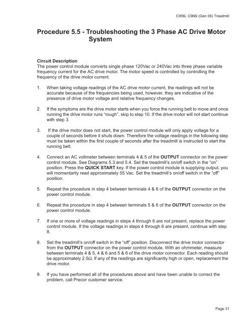
Procedure 5.5 - <strong>Troubleshooting</strong> <strong>the</strong> 3 Phase AC Drive Motor<br />
System<br />
Circuit Description<br />
The power control module converts single phase 120Vac or 240Vac into three phase variable<br />
frequency current for <strong>the</strong> AC drive motor. The motor speed is controlled by controlling <strong>the</strong><br />
frequency of <strong>the</strong> drive motor current.<br />
1. When taking voltage readings of <strong>the</strong> AC drive motor current, <strong>the</strong> readings will not be<br />
accurate because of <strong>the</strong> frequencies being used, however, <strong>the</strong>y are indicative of <strong>the</strong><br />
presence of drive motor voltage and relative frequency changes.<br />
2. If <strong>the</strong> symptoms are <strong>the</strong> drive motor starts when you force <strong>the</strong> running belt to move and once<br />
running <strong>the</strong> drive motor runs “rough”, skip to step 10. If <strong>the</strong> drive motor will not start continue<br />
with step 3.<br />
3. If <strong>the</strong> drive motor does not start, <strong>the</strong> power control module will only apply voltage for a<br />
couple of seconds before it shuts down. Therefore <strong>the</strong> voltage readings in <strong>the</strong> following step<br />
must be taken within <strong>the</strong> first couple of seconds after <strong>the</strong> treadmill is instructed to start <strong>the</strong><br />
running belt.<br />
4. Connect an AC voltmeter between terminals 4 & 5 of <strong>the</strong> OUTPUT connector on <strong>the</strong> power<br />
control module. See Diagrams 5.3 and 5.4. Set <strong>the</strong> treadmill’s on/off switch in <strong>the</strong> “on”<br />
position. Press <strong>the</strong> QUICK START key. If <strong>the</strong> power control module is supplying output, you<br />
will momentarily read approximately 55 Vac. Set <strong>the</strong> treadmill’s on/off switch in <strong>the</strong> “off”<br />
position.<br />
5. Repeat <strong>the</strong> procedure in step 4 between terminals 4 & 6 of <strong>the</strong> OUTPUT connector on <strong>the</strong><br />
power control module.<br />
6. Repeat <strong>the</strong> procedure in step 4 between terminals 5 & 6 of <strong>the</strong> OUTPUT connector on <strong>the</strong><br />
power control module.<br />
7. If one or more of voltage readings in steps 4 through 6 are not present, replace <strong>the</strong> power<br />
control module. If <strong>the</strong> voltage readings in steps 4 through 6 are present, continue with step<br />
8.<br />
8. Set <strong>the</strong> treadmill’s on/off switch in <strong>the</strong> “off” position. Disconnect <strong>the</strong> drive motor connector<br />
from <strong>the</strong> OUTPUT connector on <strong>the</strong> power control module. With an ohmmeter, measure<br />
between terminals 4 & 5, 4 & 6 and 5 & 6 of <strong>the</strong> drive motor connector. Each reading should<br />
be approximately 2.5Ω. If any of <strong>the</strong> readings are significantly high or open, replacement <strong>the</strong><br />
drive motor.<br />
9. If you have performed all of <strong>the</strong> procedures above and have been unable to correct <strong>the</strong><br />
problem, call Precor customer service.<br />
Page 31
C956i, C966i (Gen 06) Treadmill<br />
10. Connect an AC voltmeter between terminals 4 & 5 of <strong>the</strong> OUTPUT connector on <strong>the</strong> power<br />
control module. See Diagrams 5.3 and 5.4. Set <strong>the</strong> treadmill’s on/off switch in <strong>the</strong> “on”<br />
position. Press <strong>the</strong> QUICK START key. If <strong>the</strong> power control module is supplying output, you<br />
will momentarily read approximately 55 Vac.<br />
11. Repeat <strong>the</strong> procedure in step 4 between terminals 4 & 6 of <strong>the</strong> OUTPUT connector on <strong>the</strong><br />
power control module.<br />
12. Repeat <strong>the</strong> procedure in step 4 between terminals 5 & 6 of <strong>the</strong> OUTPUT connector on <strong>the</strong><br />
power control module.<br />
13. If one or more of voltage readings in steps 4 through 6 are not present, replace <strong>the</strong> power<br />
control module. If <strong>the</strong> voltage readings in steps 10 through 12 are present, skip to step 8<br />
Page 1-32 Page 32


