R8C/17 IIC Sample Project (Using HEW4 and E8) - von Gunthard ...
R8C/17 IIC Sample Project (Using HEW4 and E8) - von Gunthard ...
R8C/17 IIC Sample Project (Using HEW4 and E8) - von Gunthard ...

Create successful ePaper yourself
Turn your PDF publications into a flip-book with our unique Google optimized e-Paper software.
App199/1.0<br />
<strong>R8C</strong>/<strong>17</strong> I 2 C <strong>Sample</strong> <strong>Project</strong> (<strong>Using</strong> <strong>HEW4</strong> <strong>and</strong> <strong>E8</strong>)<br />
Introduction<br />
The purpose of this application note is to provide example serial communication code for the<br />
<strong>R8C</strong><strong>17</strong> device.<br />
The application utilises an MB<strong>R8C</strong><strong>17</strong> board, an <strong>E8</strong> debugger <strong>and</strong> a dual power supply. This<br />
board has an external crystal, a power connector, microcontroller connections <strong>and</strong> an <strong>E8</strong><br />
connector.<br />
All code was developed using Renesas’s High Performance Embedded Workshop 4 (HEW) with<br />
the M16C toolchain, Ver 5.30.02. The code was developed on an <strong>R8C</strong>/<strong>17</strong> using the On-Chip<br />
Debug functionality via an <strong>E8</strong> Emulator.<br />
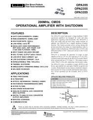
A picture of the MB<strong>R8C</strong><strong>17</strong> is shown below in figure 1.<br />
Figure 1: MB<strong>R8C</strong><strong>17</strong> board<br />
Application Note 199/1.0 July 2005 Page 1 of 30
App199/1.0<br />
Contents<br />
INTRODUCTION .......................................................................................................................................... 1<br />
CONTENTS.................................................................................................................................................. 2<br />
<strong>R8C</strong> FAMILY OVERVIEW............................................................................................................................ 4<br />
SYSTEM OVERVIEW .................................................................................................................................. 4<br />
THE LCD MODULE ..................................................................................................................................... 8<br />
HARDWARE SETUP USING I 2 C COMMUNICATION .............................................................................. 10<br />
THE I 2 C PERIPHERAL .............................................................................................................................. 13<br />
1. ICCR1 & 2 BUS CONTROL REGISTERS H’00B8 & H’00B9 ........................................... 15<br />
2. ICMR – I 2 C BUS MODE REGISTER H’00BA................................................................ <strong>17</strong><br />
3. ICIER – I 2 C BUS INTERTRUPT ENABLE REGISTER H’00BB .......................................... 18<br />
4. ICSR – I 2 C BUS STATUS REGISTER H’00BC.............................................................. 20<br />
5. SAR – SLAVE ADDRESS REGISTER H’00BD .............................................................. 21<br />
6. ICDRT – I 2 C BUS TRANSMIT DATA REGISTER H’00BE ................................................ 22<br />
7. ICDRR – I 2 C BUS RECEIVE DATA REGISTER H’00BF .................................................. 22<br />
8. ICDRS – I 2 C BUS SHIFT REGISTER................................................................................ 22<br />
SOFTWARE DESCRIPTION FOR DEMONSTRATION............................................................................ 23<br />
9. CODE PURPOSE............................................................................................................. 23<br />
10. EXTERNAL CODE OPERATION.......................................................................................... 23<br />
11. <strong>R8C</strong><strong>17</strong> WORKSPACE ..................................................................................................... 23<br />
FILE NAMES AND PURPOSES............................................................................................................... 23<br />
12. CODE FUNCTIONS .......................................................................................................... 24<br />
VOID MAIN(VOID) ................................................................................................................................ 24<br />
VOID SWITCH_MAIN_CLOCK(VOID) ...................................................................................................... 25<br />
VOID INIT_LEDS(VOID)......................................................................................................................... 26<br />
VOID FLASH_LED2(VOID).................................................................................................................... 26<br />
Application Note 199/1.0 July 2005 Page 2 of 30
App199/1.0<br />
VOID DELAY(VOID) ............................................................................................................................. 27<br />
INIT_<strong>IIC</strong>(VOID).................................................................................................................................... 27<br />
VOID WRITE_BYTES(VOID) .................................................................................................................. 28<br />
WRITE_DATA_END() ................................................................................................................................ 29<br />
CONCLUSION ........................................................................................................................................... 29<br />
Application Note 199/1.0 July 2005 Page 3 of 30
<strong>R8C</strong>/<strong>17</strong> <strong>IIC</strong> <strong>Sample</strong> <strong>Project</strong> (<strong>Using</strong> <strong>HEW4</strong> <strong>and</strong> <strong>E8</strong>)<br />
<strong>R8C</strong> Family Overview<br />
The <strong>R8C</strong> devices have an internal 16-bit architecture, 89 instructions, 2 banks of seven 16-bit<br />
registers <strong>and</strong> various peripheral functions.<br />
The relatively low pin count, peripheral mix <strong>and</strong> high performance of the <strong>R8C</strong> range make them<br />
ideal for applications within Security Alarms, Small Sensors, Utility Meters, Small applications,<br />
White Goods, toys <strong>and</strong> TV equipment plus many others.<br />
System Overview<br />
The <strong>R8C</strong><strong>17</strong> has an <strong>R8C</strong> core with 89 instructions, a minimum instruction execution time of 50nS<br />
at 20MHz <strong>and</strong> a memory space of 1 Mbyte.<br />
It has the following peripherals:<br />
• Timer X: 8 bits × 1 channel,<br />
• Timer Z: 8 bits × 1 channel<br />
• Timer C: 16 bits × 1 channel<br />
• I 2 C bus Interface (I 2 C)(1) 1 channel<br />
• A/D Converter 10-bit A/D converter: 1 circuit, 4 channels<br />
• Watchdog Timer 15 bits ×1 channel (with prescaler), Reset start selectable, Count source<br />
protection mode<br />
• Interrupt Internal: 9 factors, External: 4 factors, Software: 4 factors,<br />
• Priority level: 7 levels<br />
• Clock Generation Circuit 2 circuits<br />
• Main clock oscillation circuit (Equipped with a built-in feedback resistor), On-chip<br />
oscillator (high speed, low speed) Equipped with frequency adjustment function on highspeed<br />
on-chip oscillator<br />
• Oscillation Stop Detection Function, Main clock oscillation stop detection function<br />
• Voltage Detection Circuit Included<br />
• Power-On Reset Circuit Included<br />
Figure 2 shows the peripherals used in this demo<br />
Application Note 199/1.0 July 2005 Page 4 of 30
<strong>R8C</strong>/<strong>17</strong> <strong>IIC</strong> <strong>Sample</strong> <strong>Project</strong> (<strong>Using</strong> <strong>HEW4</strong> <strong>and</strong> <strong>E8</strong>)<br />
Figure 2: <strong>R8C</strong><strong>17</strong> Peripheral use in application<br />
Some I/O pins are used to drive LEDs. The I 2 C interface is used for communication with an<br />
LCD module. The on chip emulator was used in conjunction with an <strong>E8</strong> for code development.<br />
Application Note 199/1.0 July 2005 Page 5 of 30
<strong>R8C</strong>/<strong>17</strong> <strong>IIC</strong> <strong>Sample</strong> <strong>Project</strong> (<strong>Using</strong> <strong>HEW4</strong> <strong>and</strong> <strong>E8</strong>)<br />
Development Environment<br />
Figure 3 shows the environment (hardware <strong>and</strong> software) used to develop the application.<br />
Figure 3: Application Set-up<br />
Application Note 199/1.0 July 2005 Page 6 of 30
<strong>R8C</strong>/<strong>17</strong> <strong>IIC</strong> <strong>Sample</strong> <strong>Project</strong> (<strong>Using</strong> <strong>HEW4</strong> <strong>and</strong> <strong>E8</strong>)<br />
The laptop PC runs <strong>HEW4</strong> <strong>and</strong> has the <strong>E8</strong> drivers installed. HEW provides a code developing<br />
environment, <strong>and</strong> also allows code to be debugged on the device using the <strong>E8</strong>.<br />
A 3.3V power supply is required to power the micon board when the final application is running<br />
without intervention with the <strong>E8</strong>. The <strong>E8</strong> may be used to power the micon board when using the<br />
<strong>E8</strong> to debug the board.<br />
A 5V supply is required to power the LCD.<br />
Some interfacing circuitry was made to perform the level shifting needed between the 3V3<br />
<strong>R8C</strong><strong>17</strong> I 2 C lines <strong>and</strong> the 5V I 2 C interface on the LCD.<br />
Application Note 199/1.0 July 2005 Page 7 of 30
<strong>R8C</strong>/<strong>17</strong> <strong>IIC</strong> <strong>Sample</strong> <strong>Project</strong> (<strong>Using</strong> <strong>HEW4</strong> <strong>and</strong> <strong>E8</strong>)<br />
The LCD Module<br />
The LCD used for this application was a LCD216S made by Mindsensors; a picture of the LCD<br />
is shown in figure 4. It has a 16 column by 2-line text display <strong>and</strong> a backlight which can be<br />
turned ON/OFF via software. It is possible to communicate with the LCD module via RS232,<br />
serial peripheral interface (SPI) or I 2 C.<br />
The Pin connection for the LCD is shown in figure 4.<br />
Figure 4: LCD top view <strong>and</strong> Pin Connection<br />
The pins are as follows<br />
Pin 1: +5V supply voltage for Module<br />
Pin 2: Serial clock for I 2 C <strong>and</strong> SPI <strong>and</strong> Rx for RS232<br />
Pin 3: GND connection for Module <strong>and</strong> reference for data communication<br />
Pin 4: No connects<br />
Pin 5: Serial Data in for I 2 C <strong>and</strong> SPI<br />
Pin 6: No connects<br />
Pin 7: CS\ for SPI <strong>and</strong> RS232<br />
When the LCD is first powered from a 5V power supply, it is configured for I 2 C<br />
communications with the slave address 0xE0. A setup switch is provided on the LCD module for<br />
selection <strong>and</strong> configuration of communication interface. To enter the setup interface on the LCD<br />
module, the setup switch should be pressed whilst the power is cycled until “Setup” appears on<br />
the display. When the switch is released, the LCD will display the current communication<br />
interface settings. The desired interface may then be selected by pressing the set up switch<br />
repeatedly if required. When the correct communication settings are displayed, the module<br />
should be powered down. The module will then power up in the new communication settings.<br />
Once the LCD is appropriately set up for communication, characters may be displayed on the<br />
LCD by sending the characters' ASCII value to the LCD. Table 1 below shows the relationship<br />
of the value sent to the LCD <strong>and</strong> the character displayed on the LCD.<br />
The LCD also has a number of comm<strong>and</strong>s which may be used to move the cursor, show the<br />
cursor, clear the screen, turn the backlight On/OFF etc. All the comm<strong>and</strong>s start 0xFE (this is<br />
blank in the character table) which is then immediately followed by the comm<strong>and</strong> number.<br />
Application Note 199/1.0 July 2005 Page 8 of 30
<strong>R8C</strong>/<strong>17</strong> <strong>IIC</strong> <strong>Sample</strong> <strong>Project</strong> (<strong>Using</strong> <strong>HEW4</strong> <strong>and</strong> <strong>E8</strong>)<br />
Table 1: Relationship between the data value sent to LCD <strong>and</strong> the character displayed.<br />
Application Note 199/1.0 July 2005 Page 9 of 30
<strong>R8C</strong>/<strong>17</strong> <strong>IIC</strong> <strong>Sample</strong> <strong>Project</strong> (<strong>Using</strong> <strong>HEW4</strong> <strong>and</strong> <strong>E8</strong>)<br />
Hardware Setup <strong>Using</strong> I 2 C Communication<br />
The <strong>R8C</strong><strong>17</strong> device is operable from the 3V3 supply, however the LCD requires 5V CMOS levels<br />
at its I 2 C pins. Some hardware interface is therefore required to perform the voltage translation<br />
between the LCD <strong>and</strong> <strong>R8C</strong><strong>17</strong> device. The following figure 5 shows this hardware interface.<br />
Application Note 199/1.0 July 2005 Page 10 of 30
<strong>R8C</strong>/<strong>17</strong> <strong>IIC</strong> <strong>Sample</strong> <strong>Project</strong> (<strong>Using</strong> <strong>HEW4</strong> <strong>and</strong> <strong>E8</strong>)<br />
Figure 5: Hardware interface for I 2 C Communication between LCD <strong>and</strong> <strong>R8C</strong><strong>17</strong> device.<br />
The device used for performing the level shifting is a P82B96. This is designed for I 2 C<br />
communications up to 400KHz. For this purpose it is possible to connect the Rx <strong>and</strong> Tx lines<br />
together <strong>and</strong> connect this to one of the I 2 C communication lines. Other I 2 C applications may<br />
require that they be kept separate. The P82B96 requires that one side of the I 2 C lines operates<br />
from 5V. The other side may operate from any voltage between 2 <strong>and</strong> 15V. For this application<br />
Application Note 199/1.0 July 2005 Page 11 of 30
<strong>R8C</strong>/<strong>17</strong> <strong>IIC</strong> <strong>Sample</strong> <strong>Project</strong> (<strong>Using</strong> <strong>HEW4</strong> <strong>and</strong> <strong>E8</strong>)<br />
we require the LCD I 2 C communications to be at a 5V level <strong>and</strong> the <strong>R8C</strong><strong>17</strong> I 2 C communications<br />
to be at a 3V3 level. Therefore the VCC level of the P82B96 is set to 3V3 volts.<br />
The SDA <strong>and</strong> SCL lines on the microcontroller side are pulled to the 3V3 power supply via 4K7<br />
resistors. This is a requirement of I 2 C communications, as the devices pulls the line low when<br />
required. Similarly, therefore, the SDA <strong>and</strong> SCL lines on the LCD side also have 4K7 resistors<br />
which pull these lines to 5V. Figure 6 is a picture of the board used as the I 2 C interface<br />
Figure 6: I 2 C Interface Board<br />
5V I/P Line<br />
3V3 I/P Line<br />
LCD Connector<br />
GND Line<br />
P82B96<br />
LCD Support<br />
Pull Up Resistors<br />
Application Note 199/1.0 July 2005 Page 12 of 30
<strong>R8C</strong>/<strong>17</strong> <strong>IIC</strong> <strong>Sample</strong> <strong>Project</strong> (<strong>Using</strong> <strong>HEW4</strong> <strong>and</strong> <strong>E8</strong>)<br />
The I 2 C Peripheral<br />
• I 2 C bus format<br />
- Selectable for master / slave device<br />
- Continuous transmit/receive (shift, transmit <strong>and</strong> receive registers are independent)<br />
- Start / stop conditions are automatically generated in master mode<br />
- Automatic loading of acknowledge bit when transmit<br />
- Bit synchronization/wait function<br />
- Direct drive of the SCL <strong>and</strong> SDA pins (NMOS open drain output) is enabled<br />
• Clock Synchronous Serial Format<br />
- Continuous transmit/receive (shift, transmit <strong>and</strong> receive registers are independent)<br />
- Selectable for master / slave device<br />
- Start / stop conditions are automatically generated in master mode<br />
- Automatic loading of acknowledge bit when transmit<br />
- Bit synchronization / wait function.<br />
- Direct drive of the SCL <strong>and</strong> SDA pins (NMOS open drain output) is enabled<br />
• Detects overrun error (clock synchronous serial format)<br />
• I 2 C bus format 6 types of interrupt error<br />
- Transmit data empty, transmit ends, receive data full, arbitration lost, NACK detection<br />
<strong>and</strong> stop condition detection.<br />
• Clock synchronous serial format 4 types of interrupt error<br />
- Transmit data empty, transmit ends, receive data full <strong>and</strong> overrun error<br />
• Clock synchronous serial format<br />
- Selectable for the MSB-first or LSB-first to the data transfer direction<br />
A block diagram of the I 2 C peripheral is shown in the following figure 7<br />
Application Note 199/1.0 July 2005 Page 13 of 30
<strong>R8C</strong>/<strong>17</strong> <strong>IIC</strong> <strong>Sample</strong> <strong>Project</strong> (<strong>Using</strong> <strong>HEW4</strong> <strong>and</strong> <strong>E8</strong>)<br />
Figure 7: I 2 C Block Diagram<br />
The ICCR1 register enables the I 2 C peripheral, sets the clock rate <strong>and</strong> the operation mode. The<br />
ICCR2 register contains the busy bit, a I 2 C reset bit, start/stop generation bit <strong>and</strong> determines the<br />
SDA/SCL pin values after a read or write. The ICMR register determines MSB or LSB first<br />
transmission, contains a bit counter <strong>and</strong> a wait bit for wait insertion. The SAR register contains<br />
the slave address for the <strong>R8C</strong><strong>17</strong> device when it acts as a slave. This register also sets whether the<br />
peripheral is the I 2 C format or the clock synchronous format. The ICIER register enables the I 2 C<br />
interrupts while the ICSSR holds the status of these interrupts (flags). The <strong>IIC</strong>DRT stores<br />
transmit data, which is then transferred to the ICDRS (shift) register. The ICDRR stores any<br />
received data.<br />
Application Note 199/1.0 July 2005 Page 14 of 30
<strong>R8C</strong>/<strong>17</strong> <strong>IIC</strong> <strong>Sample</strong> <strong>Project</strong> (<strong>Using</strong> <strong>HEW4</strong> <strong>and</strong> <strong>E8</strong>)<br />
1. ICCR1 & 2 Bus Control Registers H’00B8 & H’00B9<br />
ICCR1:<br />
7<br />
6 5 4 3 2 1 0<br />
ICE<br />
RCVD<br />
MST<br />
TRS<br />
CKS3<br />
CKS2<br />
CKS1<br />
CKS0<br />
Initial Value:<br />
Read/Write:<br />
0<br />
R/W<br />
0 0 0 0 0 0 0<br />
R/W R/W R/W R/W R/W R/W R/W<br />
ICCR2:<br />
7<br />
6 5 4 3 2 1 0<br />
BBSY<br />
SCP<br />
SDAO<br />
SDAOP<br />
SCLO<br />
-<br />
ICCRST<br />
-<br />
Initial Value:<br />
Read/Write:<br />
0<br />
R/W<br />
1 1 1 1 1 0 1<br />
R/W R/W R/W R0 - R/W -<br />
Bit 7:<br />
ICE – Bus Busy Bit<br />
0: I 2 C module is halted<br />
1: I 2 C module is enabled<br />
Bit 6:<br />
RCVD – Receive Disable bit<br />
0: Enables receive operation<br />
1: Disables receive operation<br />
Bit [5:4] MST – Master/Slave Device Select bit<br />
TRS – Transmit /Receive select bit<br />
MST TRS Mode<br />
0 0 Slave Receive mode<br />
0 1 Slave Transmit mode<br />
1 0 Master Receive mode<br />
1 1 Master Transmit mode<br />
Application Note 199/1.0 July 2005 Page 15 of 30
<strong>R8C</strong>/<strong>17</strong> <strong>IIC</strong> <strong>Sample</strong> <strong>Project</strong> (<strong>Using</strong> <strong>HEW4</strong> <strong>and</strong> <strong>E8</strong>)<br />
Bit [3:0]:<br />
CKS[3:0] - Transmit Clock Select bits<br />
CKS3 CKS2 CKS1 CKS0 Transfer Rate<br />
0 0 0 0 f1/28<br />
0 0 0 1 f1/40<br />
0 0 1 0 f1/48<br />
0 0 1 1 f1/64<br />
0 1 0 0 f1/80<br />
0 1 0 1 f1/100<br />
0 1 1 0 f1/112<br />
0 1 1 1 f1/128<br />
1 0 0 0 f1/56<br />
1 0 0 1 f1/80<br />
1 0 1 0 f1/96<br />
1 0 1 1 f1/128<br />
1 1 0 0 f1/160<br />
1 1 0 1 f1/200<br />
1 1 1 0 f1/224<br />
1 1 1 1 f1/256<br />
Bit 7:<br />
BBSY – Bus Busy Bit<br />
0: The bus in in a released state<br />
1: The bus is occupied<br />
Bit 6:<br />
SCP – Start/Stop Condition<br />
Write a "0" to this bit simultaneously with the BBSY bit to generate a start bit.<br />
Bit 5:<br />
SDAO – SDA Output Value Control bit<br />
0: Read; SDA pin is held low, Write; SDA pin is changed to low<br />
1: Read; SDA pin is held high, Write; SDA pin is changed to high<br />
Application Note 199/1.0 July 2005 Page 16 of 30
<strong>R8C</strong>/<strong>17</strong> <strong>IIC</strong> <strong>Sample</strong> <strong>Project</strong> (<strong>Using</strong> <strong>HEW4</strong> <strong>and</strong> <strong>E8</strong>)<br />
Bit 4:<br />
SDAOP – SDAO Write Protect bit<br />
When rewrite to SDAO bit, write "0" simultaneously.<br />
Bit 3:<br />
SCLO – SCL Monitor Flag<br />
0: SCL pin is set to Low<br />
1: SCL pin is set to high<br />
Bit 2:<br />
Reserved<br />
Bit 1:<br />
Bit 0:<br />
ICCRST – I 2 C Control Part Reset bit<br />
When hang up occurs due to communication failure during I 2 C bus interface<br />
operation, write a "1" to reset the control part of the I 2 C bus interface without<br />
setting port <strong>and</strong> initialisaing all the registers.<br />
Reserved<br />
2. ICMR – I 2 C Bus Mode Register H’00BA<br />
7<br />
6 5 4 3 2 1 0<br />
MLS<br />
WAIT<br />
-<br />
-<br />
BCWP<br />
BC2<br />
BC1<br />
BC0<br />
Initial Value:<br />
Read/Write:<br />
0<br />
R/W<br />
0 0 1 1 0 0 0<br />
R/W R/W - R/W R/W R/W R/W<br />
Bit 7:<br />
MLS - MSB First / LSB First Select bit<br />
0: Transfers data MSB first<br />
1: Transfers data LSB first<br />
Bit 6:<br />
WAIT - SSCK Clock Polarity Select bit<br />
0: "H" when clock stops<br />
1; "L" when clock stops<br />
Bit [5:4]:<br />
Reserved<br />
Application Note 199/1.0 July 2005 Page <strong>17</strong> of 30
<strong>R8C</strong>/<strong>17</strong> <strong>IIC</strong> <strong>Sample</strong> <strong>Project</strong> (<strong>Using</strong> <strong>HEW4</strong> <strong>and</strong> <strong>E8</strong>)<br />
Bit 3:<br />
BCWP – BC Write Protect Bit<br />
Bit [2:0]: BC[2:0] - Bit counter 2 to 0<br />
Clock Synchronous Format<br />
I 2 C Bus FOrmat<br />
BC2 BC1 BC0 Bits left BC2 BC1 BC0 Bits left<br />
0 0 0 8 bit 0 0 0 9 bits<br />
0 0 1 1 bit 0 0 1 2 bits<br />
0 1 0 2 bit 0 1 0 3 bits<br />
0 1 1 3 bit 0 1 1 4 bits<br />
1 0 0 4 bit 1 0 0 5 bits<br />
1 0 1 5 bit 1 0 1 6 bits<br />
1 1 0 6 bit 1 1 0 7 bits<br />
1 1 1 7 bit 1 1 1 8 bits<br />
3. ICIER – I 2 C Bus Intertrupt Enable Register H’00BB<br />
7<br />
6 5 4 3 2 1 0<br />
TIE<br />
TEIE<br />
RIE<br />
NAKIE<br />
STIE<br />
ACKE<br />
ACKBR<br />
ACKBT<br />
Initial Value:<br />
Read/Write:<br />
Bit 7:<br />
0<br />
R/W<br />
0 0 0 0 0 0 0<br />
R/W R/W R/W R/W R/W RO R/W<br />
TIE – Transmit Interrupt Enable bit<br />
0: Transmit Interrupt is disabled<br />
1: Transmit Interrupt enabled<br />
Bit 6:<br />
TEIE – Transmit End Interrupt Enable bit<br />
0: Transmit End Interrupt is disabled<br />
1; Transmit End Interrupt is enabled<br />
Bit 5:<br />
RIE – Receive Interrupt Enable bit<br />
0: Receive Interrupt is disabled<br />
1: Receive Interrupt is enabled<br />
Application Note 199/1.0 July 2005 Page 18 of 30
<strong>R8C</strong>/<strong>17</strong> <strong>IIC</strong> <strong>Sample</strong> <strong>Project</strong> (<strong>Using</strong> <strong>HEW4</strong> <strong>and</strong> <strong>E8</strong>)<br />
Bit 4:<br />
NAKIE – NACK Receive Interrupt Enable Bit<br />
0: Disables NACK receive interrupt request<br />
1: Enables NACK receive interrupt request<br />
Bit 3:<br />
STIE – Stop Condition Detection Interrupt Enable<br />
0: Disables stop condition detection interrupt enable bit<br />
1: Enables stop condition detection interrupt enable bit<br />
Bit 2:<br />
ACKE – Acknowledge Bit<br />
0: Value of receive acknowledge bit is ignored<br />
1: Receive acknowledge bit is set to "1", continuous transfer is halted.<br />
Bit 1:<br />
ACKBR – Receive Acknowledge Bit<br />
0: Acknowledge bit received from receive device in transmit mode is set to 0<br />
1: Acknowledge bit received from receive device in transmit mode is set to 1<br />
Bit 0:<br />
ACKBT – Transmit Acknowledge Bit<br />
0: 0 is transmitted as acknowledge bit in receive mdoe<br />
1: 1 is tranmsitted as acknowledge bit in receive mode<br />
Application Note 199/1.0 July 2005 Page 19 of 30
<strong>R8C</strong>/<strong>17</strong> <strong>IIC</strong> <strong>Sample</strong> <strong>Project</strong> (<strong>Using</strong> <strong>HEW4</strong> <strong>and</strong> <strong>E8</strong>)<br />
4. ICSR – I 2 C Bus Status Register H’00BC<br />
7<br />
6 5 4 3 2 1 0<br />
TDRE<br />
TEND<br />
RDRF<br />
NACKF<br />
STOP<br />
AL<br />
AAS<br />
ADZ<br />
Initial Value:<br />
Read/Write:<br />
0<br />
R/W<br />
0 0 0 0 0 0 0<br />
R/W R/W R/W R/W R/W R/W R/W<br />
Bit 7: TDRE – Transmit Data Empty<br />
The following conditions set this flag:<br />
• Data is transferred from ICDRT to ICDRS registers <strong>and</strong> ICDRT register is empty<br />
• When setting the TRS bit in the ICCR1 register to “1” (transmit mode)<br />
• When generating the start condition (including retransmit)<br />
• When changing from slave receive mode to slave transmit mode<br />
Bit 6: TEND – Transmit End<br />
The following conditions set this flag:<br />
• When the 9th clock of the SCL signal w ith the I2C bus format w hile the TDRE bit is<br />
set to “1”, this flag is set to “1”<br />
• When the final bit of the transmit frame is transmitted w ith the clock synchronous<br />
format.<br />
Bit 5:<br />
RDRF – Receive Data Register Full<br />
This flag is set when receive data is transferred from ICDRS to ICDRR registers.<br />
Bit 4:<br />
NACKF – No Acknowledge Detection Flag<br />
This flag is set to 1 when no ACKnow ledge is detected from receive<br />
Bit 3:<br />
STOP – Stop Condition Detection Flag<br />
This flag is set to 1 when the stop condition is detected after the frame is<br />
transferred<br />
Application Note 199/1.0 July 2005 Page 20 of 30
<strong>R8C</strong>/<strong>17</strong> <strong>IIC</strong> <strong>Sample</strong> <strong>Project</strong> (<strong>Using</strong> <strong>HEW4</strong> <strong>and</strong> <strong>E8</strong>)<br />
Bit 2: AL – Overrun Error Flag<br />
When the I 2 C bus format is used, this flag indicates that arbitration is lost in master mode. In the<br />
following case, this flag is set to “1”<br />
• When the internal SDA signal <strong>and</strong> SDA pin level do not match at the rise of the SCL signal<br />
in master transmit mode<br />
• When the start condition is detected <strong>and</strong> the SDA pin is held “H” in master transmit / receive<br />
mode.<br />
This flag indicates that an overrun error occurs when the clock synchronous format is used<br />
In the follow ing case, this flag is set to “1”.<br />
• When the last bit of the follow ing data is received w hile the RDRF bit is set to 1.<br />
Bit 1: AAS - Slave Address Recognition Flag<br />
This flag is set to “1” w hen the first frame following start condition matches the SVA0 to SVA6<br />
bits in the SAR register in slave receive mode. (Detect the slave address <strong>and</strong> generate call<br />
address).<br />
Bit 0: ADZ – General Call Address Recognition Flag<br />
When detecting the general call address, this flag is set to “1”.<br />
5. SAR – Slave Address Register H’00BD<br />
7<br />
6 5 4 3 2 1 0<br />
SVA6<br />
SVA5<br />
SVA4<br />
SVA3<br />
SVA2<br />
SVA1<br />
SVA0<br />
FS<br />
Initial Value:<br />
Read/Write:<br />
0<br />
R/W<br />
0 0 0 0 0 0 0<br />
R/W R/W R/W R/W R/W R/W R/W<br />
Bit [7:1]: SVA[6:2] – Slave address 6:0<br />
Set the different address from the other slave devices which are connected to the I2C bus. When<br />
the 7 high-order bits of the first frame transmitted after the starting condition match the SVA0 to<br />
SVA6 bits in slave mode of the I2C bus format, the microcomputer operates as a slave device.<br />
Bit 0:<br />
FS – Format Select Bit<br />
0: I 2 C bus format<br />
1: Clock synchronous serial format<br />
Application Note 199/1.0 July 2005 Page 21 of 30
<strong>R8C</strong>/<strong>17</strong> <strong>IIC</strong> <strong>Sample</strong> <strong>Project</strong> (<strong>Using</strong> <strong>HEW4</strong> <strong>and</strong> <strong>E8</strong>)<br />
6. ICDRT – I 2 C Bus Transmit Data Register H’00BE<br />
This register store the transmit data. When detecting that the ICDRS register is empty, the stored<br />
transmit data is transferred to the ICDRS register <strong>and</strong> the starts transmit data. When the next<br />
transmit data is written to the ICDRT register during transmitting the data of the ICDRS register,<br />
continuous transmit is enabled. When the MLS bit in the ICMR register is set to “1” (data<br />
transferred by LSB-first) <strong>and</strong> after the data is written to the ICDRT register, the MSB <strong>and</strong> LSB<br />
inverted data is read.<br />
7. ICDRR – I 2 C Bus Receive Data Register H’00BF<br />
This register stores any received data. When the ICDRS register receives 1-byte data, the<br />
receive data is transferred to the ICDRR register <strong>and</strong> the next receive is enabled.<br />
8. ICDRS – I 2 C Bus Shift Register<br />
This register is used to transmit <strong>and</strong> receive data. The transmit data is transferred from the<br />
ICRDT to ICDRS registers <strong>and</strong> data is transmitted from the SDA pin when transmitting. When<br />
1-byte data is received, data is transferred from the ICDRS to ICDRR registers when receiving.<br />
Application Note 199/1.0 July 2005 Page 22 of 30
<strong>R8C</strong>/<strong>17</strong> <strong>IIC</strong> <strong>Sample</strong> <strong>Project</strong> (<strong>Using</strong> <strong>HEW4</strong> <strong>and</strong> <strong>E8</strong>)<br />
Software Description for demonstration.<br />
9. Code Purpose<br />
The software for this application is designed to demonstrate the I 2 C interface of the <strong>R8C</strong><strong>17</strong>.<br />
10. External code operation<br />
The software runs on MB<strong>R8C</strong><strong>17</strong>. When the code starts to execute Led 2 will flash, which<br />
notifies the user that the board is functional. The I 2 C peripheral is then initialised <strong>and</strong> then starts<br />
to communicate with the LCD. The phrase "<strong>R8C</strong><strong>17</strong>" is then displayed on the screen repeatedly.<br />
11. <strong>R8C</strong><strong>17</strong> Workspace<br />
The workspace when opened within <strong>HEW4</strong> will appear as figure 8.<br />
Figure 8: Workspace view<br />
File Names <strong>and</strong> Purposes<br />
“<strong>R8C</strong><strong>17</strong>.c”: Contains the main function called “main.c”. This function performs some system<br />
initialisations <strong>and</strong> runs the infinite loop for writing to the LCD. It also holds the LED control<br />
functions.<br />
“<strong>R8C</strong><strong>17</strong>_<strong>IIC</strong>.c”: Contains all the I 2 C initialisation <strong>and</strong> communication functions.<br />
“ncrt0.a30”: An assembly file for performing some system setups to do with memory <strong>and</strong> stack.<br />
Sets entry into main function.<br />
Application Note 199/1.0 July 2005 Page 23 of 30
<strong>R8C</strong>/<strong>17</strong> <strong>IIC</strong> <strong>Sample</strong> <strong>Project</strong> (<strong>Using</strong> <strong>HEW4</strong> <strong>and</strong> <strong>E8</strong>)<br />
12. Code Functions<br />
Void main(void)<br />
When the <strong>R8C</strong><strong>17</strong> comes out of reset the assembler code in ncrt0.a30 is run <strong>and</strong> entry into the<br />
main function occurs. The code for the main function is shown below.<br />
The first function performed by main is to switch the CPU clock from the on chip low speed<br />
oscillator to the high speed on chip oscillator. This enables the I 2 C interface to be used.<br />
LED 2 is then flashed to show that the board has successfully been reset <strong>and</strong> is working as<br />
expected.<br />
The I 2 C peripheral is then initialised for communication with the LCD. The code then enters an<br />
infinite for loop. This loop continuously performs the following functions:<br />
1. Writes a comm<strong>and</strong> via the I 2 C to the LCD to send the LCD cursor home. Any character<br />
now written to the LCD will be displayed in the top left corner of the glass.<br />
2. Writes a comm<strong>and</strong> to switch off the blinking cursor<br />
Application Note 199/1.0 July 2005 Page 24 of 30
<strong>R8C</strong>/<strong>17</strong> <strong>IIC</strong> <strong>Sample</strong> <strong>Project</strong> (<strong>Using</strong> <strong>HEW4</strong> <strong>and</strong> <strong>E8</strong>)<br />
3. Writes a comm<strong>and</strong> to clear the LCD screen<br />
4. The characters "<strong>R8C</strong><strong>17</strong>." are then written sequentially to the LCD via the I 2 C interface.<br />
A delay is present between each comm<strong>and</strong> <strong>and</strong> to ensure that the LCD has sufficient<br />
time to execute the previous comm<strong>and</strong> or to write the previous character to the screen.<br />
Void switch_main_clock(void)<br />
The code used to switch the device clock from the low speed on chip oscillator to the high speed<br />
on chip oscillator is shown below<br />
Firstly the protect bit, PRC0, is switched off to allow settings to be made to the system clock <strong>and</strong><br />
oscillation registers. The CM06 bit is then set to 1 to allow settings to be made for the CM16 <strong>and</strong><br />
CM<strong>17</strong> bits. These bits are then set to no division mode. The HRA00 bit is then set to enable the<br />
on chip oscillator <strong>and</strong> is followed by a few nops to give it time to settle. The high-speed<br />
oscillator is then selected by setting HRA01. CM06 is the cleared <strong>and</strong> the PRC0 protect bit is<br />
cleared. Any attempt to write to the system clock <strong>and</strong> oscillation registers is now invalid.<br />
Application Note 199/1.0 July 2005 Page 25 of 30
<strong>R8C</strong>/<strong>17</strong> <strong>IIC</strong> <strong>Sample</strong> <strong>Project</strong> (<strong>Using</strong> <strong>HEW4</strong> <strong>and</strong> <strong>E8</strong>)<br />
void init_leds(void)<br />
The code used to initialise the port pins connected to LED 1 <strong>and</strong> LED 2 on the MB<strong>R8C</strong><strong>17</strong> is<br />
shown below:<br />
Firstly the data port pins are cleared to 0. This will turn on the LED's when the direction registers<br />
are set as current is sunk by the device through the LED's. The direction register bits for the LED<br />
port pins are then set to 1 for output.<br />
void Flash_Led2(void)<br />
This function flashes LED2 10 times.<br />
Two loop variables are first declared, these being i <strong>and</strong> j. The first loop determines how<br />
many times the LED flashes <strong>and</strong> is set to ten times. The second <strong>and</strong> third loops determine<br />
Application Note 199/1.0 July 2005 Page 26 of 30
<strong>R8C</strong>/<strong>17</strong> <strong>IIC</strong> <strong>Sample</strong> <strong>Project</strong> (<strong>Using</strong> <strong>HEW4</strong> <strong>and</strong> <strong>E8</strong>)<br />
how long the LED is on <strong>and</strong> off for during the flash. These have to be long loops for the<br />
flash to be observable.<br />
Void Delay(void)<br />
The function Delay() is used to give the LCD time to recover from comm<strong>and</strong>s, writing<br />
text to the screen.<br />
This is a for loop which loops round for a period of time.<br />
Init_<strong>IIC</strong>(void)<br />
The initialisation procedure for the I 2 C peripheral is shown in the following code. This function<br />
performs the initialisation of the I 2 C peripheral in order that the <strong>R8C</strong><strong>17</strong> device may write bytes<br />
onto the I 2 C bus. The I 2 C bus consists of two signals, SCL <strong>and</strong> SDA. The SDA lines is used for<br />
the device to write data onto. The clock signal SCL is used to determine the timing to read/place<br />
the data on the I 2 C bus.<br />
Firstly the <strong>IIC</strong>R1 register is setup to enable the I 2 C interface <strong>and</strong> set the transfer clock rate. In<br />
this case the value 0100 is used which corresponds to 100KHz with an 8MHz oscillator. The<br />
ICMR register is then written to ensure MSB first transmission <strong>and</strong> for no wait bit. The ICIER is<br />
Application Note 199/1.0 July 2005 Page 27 of 30
<strong>R8C</strong>/<strong>17</strong> <strong>IIC</strong> <strong>Sample</strong> <strong>Project</strong> (<strong>Using</strong> <strong>HEW4</strong> <strong>and</strong> <strong>E8</strong>)<br />
cleared to ensure no interrupts are enabled <strong>and</strong> all the flags are cleared in ICSR. The code then<br />
waits for the BBSY flag to clear (i.e. it waits for the I 2 C bus to be released).<br />
void Write_bytes(void)<br />
This function transmits two bytes of data on the I 2 C bus to the LCD.<br />
The code sets the MST <strong>and</strong> TRS bit so that the I 2 C peripheral is in master transmit mode. A start<br />
condition may then be issued by writing a 1 <strong>and</strong> a 0 to the BBST <strong>and</strong> SCP bits respectively. The<br />
slave address may then be placed in the ICDRT register ready for transmission. In this case the<br />
data should only be transmitted to the LCD <strong>and</strong> not received from the LCD so the read/write part<br />
of the slave address (this is the last bit of the slave address value) is 0. The code then waits for<br />
the TEND flag in ICSR to become set, i.e. for the transmission of the slave address to finish. The<br />
first byte of data is then placed in the ICDRT register <strong>and</strong> the code waits for this to be<br />
transmitted. The last byte of data is then passed to the Write_data_End function.<br />
Application Note 199/1.0 July 2005 Page 28 of 30
<strong>R8C</strong>/<strong>17</strong> <strong>IIC</strong> <strong>Sample</strong> <strong>Project</strong> (<strong>Using</strong> <strong>HEW4</strong> <strong>and</strong> <strong>E8</strong>)<br />
Write_data_end()<br />
The Write_data_End function writes the last byte of data to be transmitted to the I 2 C interface.<br />
The last byte is put in the ICDRT register ready for transmission. The code then waits for the<br />
TEND flag to be set, which is then cleared for safety. The stop bit is then cleared <strong>and</strong> a stop<br />
condition is issued on the I 2 C bus by clearing SCP <strong>and</strong> BBSY. The transmit <strong>and</strong> master bits are<br />
cleared along with the TDRE flag.<br />
Conclusion<br />
The I 2 C peripheral of the <strong>R8C</strong><strong>17</strong> was successfully demonstrated using the Micon Board <strong>R8C</strong><strong>17</strong><br />
<strong>and</strong> an LCD. Some interfacing circuitry was used to connect the MB<strong>R8C</strong><strong>17</strong> with the LCD. Code<br />
was written which flashed LED 2 of the micon board <strong>and</strong> displayed "<strong>R8C</strong><strong>17</strong>" on the LCD.<br />
Application Note 199/1.0 July 2005 Page 29 of 30
<strong>R8C</strong>/<strong>17</strong> <strong>IIC</strong> <strong>Sample</strong> <strong>Project</strong> (<strong>Using</strong> <strong>HEW4</strong> <strong>and</strong> <strong>E8</strong>)<br />
Cautions<br />
Keep safety first in your circuit designs!<br />
• Renesas Technology Corporation puts the maximum effort into making semiconductor products better <strong>and</strong><br />
more reliable, but there is always the possibility that trouble may occur with them. Trouble with<br />
semiconductors may lead to personal injury, fire or property damage.<br />
Remember to give due consideration to safety when making your circuit designs, with appropriate measures<br />
such as (i) placement of substitutive, auxiliary circuits, (ii) use of nonflammable material or (iii) prevention<br />
against any malfunction or mishap.<br />
Notes regarding these materials<br />
• These materials are intended as a reference to assist our customers in the selection of the Renesas<br />
Technology Corporation product best suited to the customer's application; they do not convey any license<br />
under any intellectual property rights, or any other rights, belonging to Renesas Technology Corporation or a<br />
third party.<br />
• Renesas Technology Corporation a<strong>IIC</strong>mes no responsibility for any damage, or infringement of any thirdparty's<br />
rights, originating in the use of any product data, diagrams, charts, programs, algorithms, or circuit<br />
application examples contained in these materials.<br />
• All information contained in these materials, including product data, diagrams, charts, programs <strong>and</strong><br />
algorithms represents information on products at the time of publication of these materials, <strong>and</strong> are subject<br />
to change by Renesas Technology Corporation without notice due to product improvements or other<br />
reasons. It is therefore recommended that customers contact Renesas Technology Corporation or an<br />
authorized Renesas Technology Corporation product distributor for the latest product information before<br />
purchasing a product listed herein.<br />
The information described here may contain technical inaccuracies or typographical errors.<br />
Renesas Technology Corporation a<strong>IIC</strong>mes no responsibility for any damage, liability, or other loss rising<br />
from these inaccuracies or errors.<br />
Please also pay attention to information published by Renesas Technology Corporation by various means,<br />
including the Renesas Technology Corporation Semiconductor home page (http://www.renesas.com).<br />
• When using any or all of the information contained in these materials, including product data, diagrams,<br />
charts, programs, <strong>and</strong> algorithms, please be sure to evaluate all information as a total system before making<br />
a final decision on the applicability of the information <strong>and</strong> products. Renesas Technology Corporation<br />
a<strong>IIC</strong>mes no responsibility for any damage, liability or other loss resulting from the information contained<br />
herein.<br />
• Renesas Technology Corporation semiconductors are not designed or manufactured for use in a device or<br />
system that is used under circumstances in which human life is potentially at stake. Please contact Renesas<br />
Technology Corporation or an authorized Renesas Technology Corporation product distributor when<br />
considering the use of a product contained herein for any specific purposes, such as apparatus or systems<br />
for transportation, vehicular, medical, aerospace, nuclear, or undersea repeater use.<br />
• The prior written approval of Renesas Technology Corporation is necessary to reprint or reproduce in whole<br />
or in part these materials.<br />
• If these products or technologies are subject to the Japanese export control restrictions, they must be<br />
exported under a license from the Japanese government <strong>and</strong> cannot be imported into a country other than<br />
the approved destination.<br />
Any diversion or reexport contrary to the export control laws <strong>and</strong> regulations of Japan <strong>and</strong>/or the country of<br />
destination is prohibited.<br />
• Please contact Renesas Technology Corporation for further details on these materials or the products<br />
contained therein.<br />
Copyright © Renesas Technology Europe Ltd. All rights reserved<br />
Application Note 199/1.0 July 2005 Page 30 of 30