Transmission Line Model - von Gunthard Kraus
Transmission Line Model - von Gunthard Kraus
Transmission Line Model - von Gunthard Kraus

You also want an ePaper? Increase the reach of your titles
YUMPU automatically turns print PDFs into web optimized ePapers that Google loves.
Document 342-1<br />
<strong>Transmission</strong> <strong>Line</strong> <strong>Model</strong><br />
Maxi<br />
Springs<br />
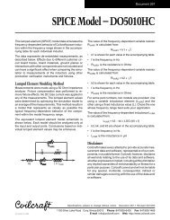
These transmission line models accurately simulate the<br />
frequency-dependent behavior of Coilcraft surface mount<br />
“Spring” air core inductors within the frequency limits<br />
shown in the accompanying table for each individual<br />
inductor. They are based on de-embedded measurements<br />
using a 2-port network analyzer.<br />
The model schematic, shown below, combines an ideal<br />
transmission line model with lumped elements. Each<br />
model should be analyzed only as a whole at the input and<br />
output ports. Conclusions based on individual lumped<br />
element values may be erroneous. The individual element<br />
values R1, R2, C, Z0, EL, and F0 are listed in the table for<br />
each individual spring inductor.<br />
P1<br />
50 Ohm<br />
C<br />
TL1<br />
Z0<br />
EL<br />
F0<br />
R1<br />
R2<br />
P2<br />
50 Ohm<br />
Effects due to different circuit board traces, board<br />
materials, ground planes or interactions with other components<br />
are not included. They will have a significant<br />
effect when comparing the simulation to measurements<br />
of the individual inductors using other production verification<br />
instruments and fixtures.<br />
Typically, the Self-Resonant Frequency (SRF) of the<br />
inductor model will be higher than a measurement of the<br />
component mounted on a circuit board. The parasitic<br />
reactive elements of a circuit board or fixture will effectively<br />
lower the circuit resonant frequency, especially for<br />
very small inductance values. Data sheet specifications<br />
are based on typical production measurements. These<br />
models are based on de-embedded 2-port measurements<br />
as described below, so the model results may be different<br />
from the data sheet specifications.<br />
Lumped Element <strong>Model</strong>ing Method<br />
The measurements were made over a brass ground plane<br />
with each component centered over an air gap, as<br />
illustrated in Figure 1. The gap width for the Maxi Spring<br />
is 0.120 in. (3,048 mm). The test pads were 30 mil<br />
(50 Ohm) wide traces of tinned gold over 25 mil thick<br />
alumina, and were not included in the gap. The TRL*<br />
calibration plane is also illustrated in Figure 1.<br />
Calibration<br />
plane<br />
The lumped element values were determined by matching<br />
the simulation model to an average of the measurements.<br />
This method results in a model that represents as closely<br />
as possible the typical frequency-dependent behavior of<br />
the component within the specified frequency limits of the<br />
model. The lumped element models were used to<br />
generate our 2-port S-parameters and therefore give<br />
identical results with the same number of simulation<br />
frequency points. The S-parameters are available on<br />
our web site at http://www.coilcraft.com/models.cfm.<br />
Disclaimer<br />
Pad Air gap Pad Brass<br />
ground<br />
plane<br />
Figure 1. Test Setup<br />
Coilcraft makes every attempt to provide accurate measurement<br />
data and software, representative of our components,<br />
in a usable format. Coilcraft, however, disclaims<br />
all warrants relating to the use of its data and software,<br />
whether expressed or implied, including without limitation<br />
any implied warranties of merchantability or fitness for a<br />
particular purpose. Coilcraft cannot and will not be liable<br />
for any special, incidental, consequential, indirect or<br />
similar damages occurring with the use of the data and/<br />
or software.<br />
Specifications subject to change without notice. Document 342-1 Revised 05/28/03
Document 342-2<br />
<strong>Transmission</strong> <strong>Line</strong> <strong>Model</strong> for Coilcraft Maxi Springs<br />
Frequency limit<br />
Part of <strong>Model</strong> (MHz) TL1<br />
number Lower Upper R1 () R2 () C (pF) Z0 () EL (degrees) F0 (MHz)<br />
132-09SM 1 1500 1.921 0.2452 0.1774 307.5 76.06 725.2<br />
132-10SM 1 1200 2.221 0.3273 0.2105 336.5 77.28 654.7<br />
132-11SM 1 1200 1.963 0.3840 0.2520 363.2 82.64 646.3<br />
132-12SM 1 1000 2.341 0.4527 0.2103 443.0 86.95 638.5<br />
132-13SM 1 1000 8.285 0.5557 0.1789 515.7 94.73 664.5<br />
132-14SM 1 1000 10.000 0.6117 0.2089 511.0 91.76 592.9<br />
132-15SM 1 920 9.601 0.6547 0.2133 516.5 79.87 471.6<br />
132-16SM 1 850 9.309 0.8173 0.2071 579.4 77.34 411.7<br />
132-17SM 1 720 8.766 1.000 0.1808 650.3 78.17 378.2<br />
132-18SM 1 670 8.411 1.091 0.2221 645.7 87.64 381.0<br />
132-19SM 1 670 10.56 1.276 0.1823 756.7 93.23 408.1<br />
132-20SM 1 550 13.05 1.476 0.2130 722.8 88.90 341.4<br />
Specifications subject to change without notice. Document 342-2 Revised 05/28/03