BV 70 E.indd - Tools.by
BV 70 E.indd - Tools.by
BV 70 E.indd - Tools.by

Create successful ePaper yourself
Turn your PDF publications into a flip-book with our unique Google optimized e-Paper software.
IT - Generatore d’aria Calda<br />
GB - Portable forced air heaters<br />
DE - Tragbare hochdruck-heissluftturbinen<br />
ES - Calentadores móviles de aire forzado<br />
FR - Appareils de chauffage individuels à air forcé<br />
NL - Mobiele ventilator-luchtverwarmer<br />
PT - Aquecedores portáteis com ventilação forçada<br />
DK - Flytbare luftcirkulations apparater<br />
FI - Siirrettävä kuumailmapuhallin<br />
NO - Flyttbar varmekanon<br />
SV - Portabel varmluftsfläkt<br />
PL - Przenośne nagrzewnice powietrza pod ciśnieniem<br />
RU - Тепловой генератор<br />
CZ - Přenosná topná tělesa na dm chan vzduch<br />
HU - Hordozható hőlégfúvók<br />
Libretto uso e manutenzione - Operation and maintenance manual -<br />
Bedienungsanweisung - Manual del proprietario - Manuel de L’utilisateur<br />
- Gebruiksaanwijzing en onderhoud - Manual de instruções - Brugs- og vedli<br />
geholdelsesvejledning - Käyttö-ja huoltokirja - Bruks- og vedlikeholdsmanual<br />
- Bruksanvisning - Instrukcja obsługi i konserwacji - Руководство по<br />
эксплуатации и уходу - Návod k použití a k údržbě - Használati utasítás<br />
<strong>BV</strong> <strong>70</strong> E<br />
.
2<br />
<strong>BV</strong> <strong>70</strong> E<br />
SPECIFICATIONS - SPÉCIFICATIONS - TECHNISCHE DATEN - TECHNISCHE<br />
GEGEVENS - DATI TECNICI - ASPECIFICACIONES - CARACTERÍSTICAS<br />
TÉCNICAS - TEKNISKE KARAKTERISTIKKER - SPECIFIKATIONER<br />
- SPECIFIKATIONER - TECHNICKÉ ÚDAJE - MŰSZAKI ADATOK -<br />
SPESIFIKASJONER - SPECYFIKACJE - TEXHИЧECKИE XAPAKTEPИCTИKИ<br />
Potenza max - Max power - Max Wärmeleistung - Potencia max - Puissance ther. max. -<br />
Max Vermogen - Värmestyrka max - Enimmäislämpöteho - Maks. Termisk Effekt - Maksimal<br />
varmeeffekt - Wydajność - Hoминaльнaя выxoднaя мoщнocть - Teljesítmény - Jmenovitá<br />
vákon<br />
- Portata d’aria - Air output - Luftstrom - Heißluftausstoß - Salida de aire caliente - Débit<br />
D’air - Blaasvermogen hete lucht - Hetluftsutsläpp - Kuumailmateho - Varmluftmængde i m3<br />
i minuttet - Varmluftskapasitet - Wydajnosc cieplego powietrza - Bыxoд гopячeгo вoздyxa<br />
- Meleg levegő kibocsátás - Vástup horkého vzduchu<br />
Consumo di combustibile - Fuel Consumption - Kraftstoffverbrauch - Consumo<br />
de combustible - Consommation Fuel - Brandstofverbruik - Bränsleförbrukning -<br />
Polttoaineenkulutus - Petroleumsforbrug - Brennstofforbruk - Zuzycie paliwa - Pacxoд<br />
топлива - Fűtőolaj fogyasztás - Spotreba paliva<br />
<strong>BV</strong> <strong>70</strong> E<br />
17 kW<br />
15.000 Kcal/h<br />
550 m³/h<br />
1,47 kg/h<br />
Combustibile - Fuel - Kraftstoff - Combustible - Brandstof - Bränsle - Polttoaine - Brændstof<br />
- Brennstoff - Paliwo - Toпливо - Fűtőolaj - Palivo diesel<br />
Capacità serbatoio - Fuel Tank Capacity - Kraftstofftank / Fassungsvermögen - Capacidad<br />
del tanque de combustible - Capacité Du Reservoir Fuel - Tankinhoud - Tankstorlek -<br />
40 Lt<br />
Polttoainesäiliön tilavuus - Tankkapacitet i liter - Størrelse på brennstofftanken - Pojemność<br />
zbiornika paliwa - Eмкость топливного бaкa - Fűtőolajtartály térfogata - Kapacita palivové<br />
nádrže<br />
Temperatura di gittata a 20 cm di distanza e 15°C temperatura ambiente 98 °C<br />
Alimentazione elettrica - Electric Requirements - Elektrischer Anschluß - Tension-V -<br />
Requisitos eléctricos - Netvoeding - Elektrisk ström - Sähkövirta - El-type - Elektriske krav<br />
230 V / 50 Hz<br />
- Wymagania odnosnie zasilania - Элeктpoпитaниe - Villamos csatlakozás - Potrebné<br />
elektrické napetí<br />
Potenza assorbita - Electric power absorbed - Aufgenommene E-Leistung - Potencia<br />
300 W<br />
eléctrica absorbida - Puissance électrique absorbée - Geabsorbeerd elektrisch vermogen<br />
- Potência eléctrica absorvida - Absorberet elektrisk kraft - Ottoteho - Forbruk elektrisitet<br />
- Upptagen elektrisk effekt - Pobór mocy - Поглощаeмая элeктричeская мощность - V kon<br />
spotřebovane elektřiny - Felvett teljesítmény<br />
Forma di corrente<br />
AC<br />
Peso - Weight - Gewicht - Peso - Poids - Gewicht - Varmeapparat vægt - Lämmittimen paino -<br />
40 kg<br />
Vekt varmekanon - Vikt värmefläkt - Cię ar nagrzewnicy - Вeс нагрeватeля - Hmotnost topného<br />
tělesa - Hőlégfúvó súlya<br />
Ø uscita fumi - Ø of fume outlet - Durchmesser Abgasrohr - Ø salida humos - Ø sortie fumée<br />
- Ø rookafvoer - Ø da saída de gases - Røgudgang Ø - Savukaasun poistoputken halkaisija<br />
120 mm<br />
- Ø røykutførsel - Ø skorstensutlopp - Średnica wylotu spalin - Диамeтр выходного<br />
отвeрстия дыма - Průměr v pustě kouře - Füstgázelvezetés átmérő<br />
Ugello - Nozzle - Düse - Boquilla - Buse - Straalpijp - Bico - Dyse - Polttoainesuutin - Kran -<br />
Munstycke - Dysza - Форсунка - Tryska - Fúvóka 0,40 US gal/h 80°<br />
Prex pompa - Fuel pump pressure - Druck Brennstoffpumpe - Presión bomba combust.<br />
- Pression pompe combust. - Druk brandstofpomp - pressão da bomba de combust. -<br />
9,5 bar<br />
Brændstofpumpe tryk - Polttoainepumpun paine - Trykk i oljepumpen - tryck bränslepump<br />
- Ciśnienie pompy paliwa - Давление насоса топлива - Tlak čerpadla paliva -<br />
Üzemanyagszivattyú noyomás
HOT AIR GENERATOR<br />
7<br />
GB<br />
CONTENTS<br />
IDENTIFICATION OF PART “B” AND “<strong>BV</strong>” 7<br />
SAFETY INFORMATION 7<br />
STARTING THE HEATER 7<br />
TURNING OFF THE HEATER 8<br />
SAFETY DEVICES 8<br />
MOVING AND TRANSPORTING THE HEATER 8<br />
PREVENTATIVE MAINTENANCE PROGRAMME 8<br />
HEATER FUNCTIONING DIAGRAM 9<br />
ELECTRIC CONTROL PANEL 9<br />
TROUBLESHOOTING 10<br />
IDENTIFICATION OF PART “B”<br />
AND “<strong>BV</strong>”<br />
Series B is a line of hot air generators with direct heating system<br />
that mix the heat released externally with combustion residues.<br />
These heaters are particularly suitable to be used for heating,<br />
defrosting and drying both outdoors and in areas with frequent<br />
air exchanges.<br />
Series <strong>BV</strong> is a line of hot air generators with indirect heating<br />
system. These generators have a heat exchanger that enables<br />
to separate exhaust combustion gases from the heat released in<br />
the environment, so that it is possible to inject a fl ow of clean hot<br />
air in the area that needs to be heated and to discharge exhaust<br />
fumes externally.<br />
Series B and <strong>BV</strong> hot air generators are designed in compliance<br />
with current safety, performance and life standards, are fitted<br />
with safety devices confi gured to guarantee continuous<br />
operation, minimize noise and are manufactured in carefully<br />
selected materials that ensure maximum reliability.<br />
SAFETY INFORMATION<br />
WARNING<br />
IMPORTANT: Read the manual carefully before attempting<br />
to assemble,switch on or service this heater. The use<br />
of the heater may cause serious or fatal injuries resulting<br />
from burns, fire, explosion, electrical discharge or carbon<br />
monoxide poisoning.<br />
DANGER:Carbon monoxide poisoning can be fatal!<br />
Carbon monoxide poisoning The fi rst symptoms of carbon<br />
monoxide poisoning are similar to those of fl u, with headache,<br />
dizziness and/or nausea.These symptoms may be caused <strong>by</strong><br />
the defective functioning of the heater. Go outside into the open<br />
air immediately! Have the heater repaired. Some people feel<br />
the effects of carbon monoxide to a greater extent, especially<br />
pregnant women, those suffering from anaemia, cardiac or lung<br />
conditions, those who are drunk and anyone at a high altitude.<br />
Ensure that you have read and understood all the warnings.<br />
Keep this manual for future reference – it is a guide to the safe<br />
and correct functioning of the heater.<br />
• Use only fuel oil no.1 in order to avoid the risk of fi re or explosion.<br />
Never use petrol, naphtha, paint solvents, alcohol or other<br />
highly infl ammable combustibles.<br />
• Fuelling<br />
a) The individual responsible for fuelling the heater must have<br />
the relevant competence and be completely familiar with the<br />
manufacturer’s instructions and with current norms concerning<br />
the safe fuelling of the heaters.<br />
b) Only use the type of fuel expressly specifi ed on the identifi cation<br />
label of the heater.<br />
c) Before adding fuel, extinguish all fl ames, including the pilot<br />
light, and wait until the heater has cooled down.<br />
d) While adding fuel, inspect all the fuel lines and joins to make<br />
sure there are no leaks.<br />
Any leak whatsoever must be repaired before switching on<br />
the heater.<br />
e) In no circumstances must more than one day’s supply of<br />
fuel be stored in the same building in proximity to the heater.<br />
Fuel storage tanks must be kept in a separate location.<br />
f) All fuel tanks must be kept at a minimum distance from heaters,<br />
oxyacetylene torches, welding equipment etc. (with the<br />
exception of the fuel tank incorporated into the heater) following<br />
regulations.<br />
g) Wherever possible, fuel should be stored in a place where<br />
the fl oor does not allow fuel to seep through and drip onto live<br />
fl ames beneath, which might cause fi re.<br />
h) Fuel must be stored in compliance with current norms.<br />
• Never use the heater anywhere where petrol, paint solvents or<br />
other highly infl ammable vapours are present.<br />
• While using the heater, follow all local ordinances and current<br />
norms.<br />
• Heaters used in the proximity of tarpaulins, curtains<br />
or other covering materials must be situated<br />
at a safe distance following regulations.<br />
It is also recommended to use fi reproof materials.<br />
These materials should be fi xed safely so as to ensure that<br />
they do not catch fi re and are not blown <strong>by</strong> the wind.<br />
• Only use in locations where there are no infl ammable fumes or<br />
high concentrations of dust.<br />
• Power the heater only with electric power that has the voltage,<br />
frequency and number of phases specified on the identifi cation<br />
label.<br />
• Only use earthed three-wire extension cords.<br />
• In order to avoid the risk of fi re, make sure the heater is on a<br />
fi rm, fl at surface when it is being used or is hot.<br />
• When moving or storing the heater, keep it level to avoid fuel<br />
loss.<br />
• Keep children and animals away from the heater.<br />
• Disconnect the heater from the mains supply when not in use.<br />
• When controlled <strong>by</strong> a thermostat, the heater may come on at<br />
any moment.<br />
• Never use the heater in frequently used rooms or in bedrooms.<br />
• Never obstruct the air intake (rear end) or the air output (front<br />
end) of the heater.<br />
• When the heater is hot, connected to the mains supply or in<br />
use, it must never be moved, handled, fi lled up with fuel or<br />
serviced in any way.<br />
STARTING THE HEATER<br />
Before turning on the heater and therefore before attaching it<br />
to the mains power supply, check that the characteristics of the<br />
mains power supply are the same as those indicated on the<br />
identifi cation label.
8<br />
GB<br />
HOT AIR GENERATOR<br />
WARNING:The electric power cable of the heater must<br />
be earthed and must have a differential magnetothermal<br />
switch.The electric plug must be connected to a socket<br />
which has a disconnecting switch.<br />
The heater can only work automatically when a control mechanism,<br />
for example a thermostat or clock, is connected to it <strong>by</strong> attaching<br />
the cable to terminals 3 and 4 of plug 3 (Fig.2) supplied<br />
with the product (the electric wire that links the two terminals<br />
must be removed and remounted only if the heater is to be used<br />
without the control mechanism).<br />
To turn on the machine, do the following:<br />
• If the control mechanism is connected, adjust it so that the<br />
machine can function (for example, the thermostat must be set<br />
to the maximum temperature).<br />
• Flip switch 1 (Fig. 2) to the position with the symbol: ON – the<br />
fan comes on and after several seconds the heater starts burning.<br />
The fi rst time the heater is used, or after the fuel circuit has been<br />
completely drained, the fl ow of fuel oil to the nozzle may be insuffi<br />
cient and may activate the fl ame cut out mechanism, which<br />
will turn off the heater;if this happens, wait for about a minute<br />
and then press the reset button 1 (Fig. 2) to start the machine<br />
again.<br />
The fi rst steps to take if the machine does not work are the<br />
following:<br />
1. Check that there is fuel in the tank.<br />
2. Press the reset button 1 (Fig.2) ON.<br />
3. If the heater still does not work, consult the<br />
“TROUBLESHOOTING”guide.<br />
Before lifting or moving the heater, make sure that the fuel tank<br />
cap is fi rmly in place.<br />
The heater may be supplied in a portable version, with wheels,<br />
or a suspended version, mounted on a support structure and<br />
fi xed in place with wires or chains. In the former case, to move<br />
the heater, simply grasp the support handle and wheel the heater.<br />
In the latter case, the heater must be lifted with a fork-lift<br />
truck or a similar piece of equipment.<br />
PREVENTATIVE MAINTENAN-<br />
CE PROGRAMME<br />
To ensure that the heater continues to work properly, it is necessary<br />
to periodically clean the combustion chamber, the burner<br />
and the fan.<br />
WARNING The following steps must be carried out before<br />
servicing the heater: turn the heater off, following the<br />
instructions in the previous section; disconnect the plug<br />
from the power supply and wait for the heater to cool.<br />
Every 50 hours of use it is necessary to:<br />
• Dismantle the fi lter cartridge, remove it and clean it with clean<br />
fuel oil.<br />
• Remove the exterior cylindrical casing and clean the inside<br />
and the blades of the fan.<br />
• Check the condition of the cables and the high voltage connections<br />
on the electrodes.<br />
• Dismantle the burner, clean the parts, then clean the electrodes<br />
and regulate them to the distance indicated on page 61 in<br />
the electrode regulation diagram.<br />
TURNING OFF THE HEATER<br />
To turn off the machine, move switch 1 (Fig. 2) to the “0” position<br />
or adjust the control mechanism, for example turning the thermostat<br />
to a lower position. The fl ame will go off and the fan will<br />
continue to function until the combustion chamber has cooled<br />
down completely.<br />
SAFETY DEVICES<br />
The heater is equipped with an electronic device to control the<br />
fl ame.If there is an anomaly in the functioning, the machine will<br />
be turned off and the reset button light 1 (Fig.2) will come on.<br />
An over-heating thermostat cuts in and shuts off the fuel supply<br />
if the heater overheats:the thermostat resets itself automatically<br />
when the temperature in the combustion chamber diminishes<br />
and reaches the maximum permitted value.<br />
Before turning the heater on again, the cause of the overheating<br />
must be identifi ed and removed (for example, a blockage in the<br />
suction orifi ce and/or of the air fl ow duct, the non-functioning<br />
of the fan). To turn on the machine again, press the reset button<br />
and repeat the specifi c instructions outlined in the section<br />
“STARTING THE HEATER”.<br />
MOVING AND TRANSPORTING<br />
THE HEATER<br />
WARNING The following steps must be carried out before<br />
moving the heater: turn the heater off, following the<br />
instructions in the previous section; disconnect the plug<br />
from the power supply and wait for the heater to cool.
HOT AIR GENERATOR<br />
9<br />
GB<br />
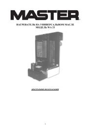
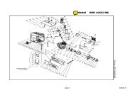
HEATER FUNCTIONING DIAGRAM<br />
1 2 3 4 5 6<br />
7 8 9<br />
10<br />
11<br />
Figur 1 - Heater functioning diagram.<br />
1. Combustion chamber, 2. Anti-wind fl ue connection, 3. Burner, 4. Nozzle,<br />
5. Fuel circuit, 6. Electric fuel valve, 7. Fuel pump, 8. Motor, 9. Fan,<br />
10. Filter, 11. Fuel tank.<br />
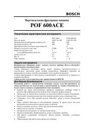
ELECTRIC CONTROL PANEL<br />
1 2 3 4<br />
Figur 2 - Electric control panel.<br />
1. Main cable, 2. Power indicator, 3. Socket for ambient thermostat,<br />
4. Power cable.
10<br />
GB<br />
HOT AIR GENERATOR<br />
TROUBLESHOOTING<br />
Observed fault Possible cause Solution<br />
The fan does not come on<br />
and the fl ame does not light<br />
The fan comes on but the<br />
fl ame does not light or does<br />
not remain lit<br />
The fan comes on and the<br />
fl ame lights, but produces<br />
smoke<br />
The heater does not switch<br />
off<br />
1. No electric current<br />
2. Incorrect setting on the control mechanism<br />
(if fitted)<br />
3. Faulty control mechanism<br />
4. Motor winding burnt out or broken<br />
1. Ignitor is not functioning<br />
2. Faulty flame cut out mechanism<br />
3. Non-functioning photoelectric cell<br />
4. Fuel is not reaching the burner or a suffi -<br />
cient a mount is not arriving<br />
5. Electric valve is not functioning<br />
1 Insuffi cient air for combustion<br />
2 Too much air for combustion<br />
3 Fuel is dirty or contains water<br />
4 Air has fi ltered into the fuel circuit<br />
5 Inadequate quantity of fuel in burner<br />
6 Too much fuel in burner<br />
1.Defective electric valve seal<br />
1a Check the characteristics of the electrical system<br />
(230V - 1~ - 50 Hz)<br />
1b Check that the switch works and is in the correct<br />
position<br />
1c Check that the fuse has not blown<br />
2 Check that the control mechanism setting is correct<br />
(e.g.the temperature setting on the thermostat must<br />
be higher than the ambient temperature)<br />
3 Replace the control mechanism<br />
4 Replace the motor<br />
1a Check the connections of the ignition cables to the<br />
electrodes and transformer<br />
1b Check the position of the electrodes and the<br />
distance between them, in accordance with the<br />
diagram<br />
1c Check that the electrodes are clean<br />
1d Replace the ignition transformer<br />
2 Replace the mechanism<br />
3 Clean or replace the photoelectric cell<br />
4a Check that the connection between the pump and<br />
the motor is intact<br />
4b Check that air has not filtered into the fuel circuit,<br />
checking the tubes and the fi lter seal<br />
4c Clean or, if necessary, replace the nozzle<br />
5a Check the electrical connection<br />
5b Check the LI thermostat<br />
5c Clean or, if necessary, replace the electricvalve<br />
1a Remove anything blocking or obstructing theaspiration<br />
and/or airfl ow ducts<br />
1b Check the position of the air regulation ring<br />
1c Clean the burner disc<br />
2 Check the position of the air regulation ring<br />
3a Replace the fuel with clean fuel<br />
3b Clean the fuel fi lter<br />
4 Check the condition of the tubes and the sealof the<br />
fuel fi lter<br />
5a Check the pump pressure<br />
5b Clean or replace the nozzle<br />
6a Check the pump pressure<br />
6b Replace the nozzle<br />
1.Replace the electric valve part<br />
The fan does not switch off 1.Faulty fan thermostat 2.Replace the FA thermostat
59<br />
REGOLAZIONE ELETTRODI - REGULATION OF ELECTRODES -<br />
EINSTELLUNG DER ELEKTRODEN - REGULACIÓN ELECTRODOS -<br />
RÉGLAGE DES ÉLECTRODES - ELEKTRODE-AFSTELLING - REGULAGEM<br />
DOS ELETRODOS - ELEKTRODE JUSTERING - ELEKTRODIEN SÄÄTÖ<br />
- REGULERING AV ELEKTRODER - ELEKTRODREGLERING - REGULACJA<br />
ELEKTROD - PEГУЛИPOBKA ЭЛEKTPOДOB - REGULACE ELEKTROD -<br />
ELEKTRÓDÁK BEÁLLÍTÁSA<br />
2-3 mm<br />
REGOLAZIONE SERRANDA ARIA COMBURENTE - REGULATION<br />
OF COMBUSTION AIR SHUTTER - REGELUNG DER<br />
VERBRENNUNGSLUFTKLAPPE - REGULACIÓN REGISTRO AIRE<br />
PARA LA COMBUSTIÓN - RÉGLAGE DU RIDEAU AIR COMBURANT -<br />
AFSTELLING VERBRANDINGSLUCHTKLEP - REGULAGEM DA VÁLVULA<br />
DE AR COMBURENTE - ILTNÆRENDE LUFTSLUSE JUSTERING -<br />
POLTTOILMAN OTON SÄÄDÖT - REGULERING AV VARMLUFTSGITTERET<br />
- FLÖDESREGLERING LUFT-BRÄNSLESJÄLL - REGULACJO POKRYWY<br />
POWIETRZE Z PALIWEM - PEГУЛИPOBKA ЗACЛOHKИ BOЗДУXA,<br />
ПOДДEPЖИBAЮЩEГO ГOPEHИE - REGULACE HRADÍTKA SPALOVACÍHO<br />
VZDUCHU - ÉGÉSI LEVEGŐ ZSALU SZABÁLYOZÁSA<br />
A<br />
A= 3,5 mm (<strong>BV</strong> <strong>70</strong> E)
60<br />
SCHEMA DI FISSAGGIO - FLUE CONNECTIONS DIAGRAM - BEFESTIGUNG<br />
DES RAUCHABZUGS - ESQUEMA FIJACIÓN CHIMENEA - SCHÉMA DE<br />
FIXATION DE LA CHEMINÉE - AFVOERMONTAGESCHEMA - ESQUEMA DE<br />
FIXAÇÃO DA CHAMINÉ - SKORSTEN FASTGØRELSESSKEMA - SAVUPIIPUN<br />
KIINNITYSKAAVIO - OVERSIKT OVER FASTMONTERING AV SKORSTEIN -<br />
INFÄSTNING AV KAMINRÖR - SCHEMAT ZAMOCOWANIAKOMINA - CXEMA<br />
KPEПЛEHИЯ BOЗДУXOBOДA<br />
1. Ø 120 mm<br />
1.<br />
SCHEMA POSIZIONAMENTO TUBO FUMI - FLUE PIPE POSITIONING<br />
DIAGRAM - ANBRINGUNG DES ABZUGSROHRS - ESQUEMA<br />
POSICIONAMIENTO TUBO HUMOS - SCHÉMA DE POSITIONNEMENT DU<br />
CONDUIT DE FUMÉE - PLAATSINGSSCHEMA ROOKBUIS - ESQUEMA DE<br />
COLOCAÇÃO DO TUBO DA CHAMINÉ - RØGRØR INSTALLERINGSSKEMA<br />
- SAVUKAASUN POISTOPUTKIEN KIINNITYSKAAVIO - OVERSIKT OVER<br />
PLASSERING AV RØYKUTFØRSELSRØR - SKORSTENENS PLACERING<br />
OCH DIMENSIONER - SCHEMAT ZAINSTALOWANIA RURY SPALIN - CXEMA<br />
PACПOЛOЖEHИЯ ДЫMOBOЙ TPYБЫ - SCHÉMA UMÍSTĚNÍ TRUBEK NA<br />
KOUŘ<br />
A= >1m<br />
B= >1m<br />
C= il più corto possibile/as short as<br />
possible/so kurz wie möglich/lo más<br />
corto posible/le plus court possible/zo<br />
kort mogelijk/o mais curto possível/så<br />
kort som muligt/lyhin mahdollinen/<br />
så kort som mulig/minsta möjliga<br />
avstånd/Najbardziej mo liwie krótki/<br />
Как можно мeньшe/Pokud možno co<br />
nejkratší/A lehető legrövidebb<br />
D= ≥ 120 mm<br />
1= > 5°<br />
A<br />
1<br />
C<br />
D<br />
B
61<br />
SCHEMA ELETTRICO - ELECTRIC DIAGRAM - ELEKTROSCHALTPLAN -<br />
ESQUEMA ALÁMBRICO - SCHÉMA ÉLECTRIQUE - BEDRADINGSSCHEMA<br />
- ESQUEMA ELÉCTRICO - ELEKTRISK SKEMA - SÄHKÖKAAVIO - OVERSIKT<br />
OVER ELEKTRISKE FUNKSJONER - ELSCHEMA - SCHEMAT ELEKTRYCZNY<br />
- ЭЛEKTPOCXEMA - SCHÉMA ELEKTŘINY - VILLAMOS BEKÖTÉSI RAJZ<br />
FU= 4 A<br />
FU= Fusibile/Fuse/Schmelzsicherung/Fusible/Zekering/Fusível/Sikring/Sulake/Sikring/Säkring/Bezpiecznik topikowy/Прeдохранитeль/Tavná pojistka/Olvadóbiztosíték<br />
IT=trasformatore alta tensione/High voltage transformer/Hochspannungstransformator/Transform. alta tensión/Transform. haute tension/Hoogspanningstransformat<br />
or/Transform. de alta tensão/Højspænding transform./Korkeajännitemuuntaja/Høyspenningstransformator/Transform. hög spänning/Transform.o wysokim napięciu/<br />
Tрансформатор высокого напряжeния/Transform.vysokého napûtí/Nagyfeszültség transzformátor<br />
EV=elettrovalvola/Electric valve/Elektroventil/Electro-válvula/Électrovanne/Elektromagnetische klep/Eletroválvula/Sähköventtiili/Elventil/Elektrozawór/Элeктрокпан/<br />
Elektrick ventil/Mágnesszelep<br />
FO=fotoresistenza/Photoresistance/Fotozelle/Fotorresistencia/Photorésistance/Fotoweerstand/Fotoresistência/Fotomodstand/Valovastus/Fotoresistens/Fotocell/<br />
Fotoodpornoś/Фоторeзистор/Fotoelektrick odpor/Fotoellenállás<br />
FA=termostato ventilatore/Fan thermostat/Ventilatorthermostat/Termostato ventilador/Thermostat ventilateur/Thermostaatventilator/Termostato do ventilador/Blæser<br />
termostat/Tuulettimen termostaatti/Viftetermostat/Termostat fläkt/Termostat wentylator/Teрмостат вeнтилятора/Termostat ventilátoru/Ventilátor termosztát<br />
MV=motore ventilatore/Fan/Ventilatormotor/Motor ventilador/Moteur ventilateur/Motorventilator/Motor do ventilador/Blæser motor/Moottorin tuuletin/Viftemotor/<br />
Fläktmotor/Silnik wentylator/Мотро вeнтилятора/Motor ventilátoru/Ventilátor motor<br />
SB=spia tensione/Power indicator/Spannungsanzeige/Luz indicadora tensión/Témoin de tension/Spanningsspion/Sinal de tensão elétrica/Spænding kontrollampe/<br />
Jännitteen merkkivalo/Varsellampe, trykk/Indikeringslampa spänning/Wskaźnik napięcia/Индикатор напряжeния/Kontrolka napûtí/Feszültség jelzőlámpa<br />
IN=Interruttore-Riarmo/Switch-Reset/Schalter-Entrigelungs/Interruptor-Restablecimiento/Interrupteur-Rearmement/Schakelaar/Kontakt/Katkaisija/Bryter/<br />
Brytarkontakt/Wyłącznik/Пeрeключатeль/Spínaã/Megszakító<br />
TA=presa termostato ambiente/Ambient therm. socket/Steckvorrichtung Raumthermostat/Toma termostato ambiente/Prise therm. ambiant/Aansluiting kamerthermostaat/<br />
Tomada term. ambiente/Indvendig temperatur term. stik/Huoneenlämpötermostaatin pistoke/Kontakt for romtermostaten/Uttag för extern term./Gniazdo termostatu<br />
pokojowego/Рoзeтка тeрмостата внeшнeй срeды/Zásuvka termostatu pro okolní ovzduší/Környezeti levegő termosztát csatlakozó<br />
R=relè/Relay/Relais/Relê/Relæ/Relä/Przekaźnik/Peлe<br />
AP=apparecchiatura di controllo/Control equipment/Steuergerät/Dispositivo de control/Appareillage de contrôle/Controle-instrument/Aparelhagem de controle/<br />
Kontrolanordning/Valvontalaite/Kontrollapparat/Styrapparatur/Aparatura kontrolna/Контрoльныe приборы/Kontrolní zafiízení/Vezérlő készülék
IT - CERTIFICATO CE DI CONFORMITÀ<br />
GB - CERTIFICATE CE OF CONFORMITY<br />
DE - KONFORMITÄTSBESCHEINIGUNG<br />
ES - CERTIFICADO CE DE CONFORMIDAD<br />
FR - CERTIFICAT CE DE CONFORMITE<br />
NL - CE CONFORMITEITSVERKLARING<br />
PT - CERTIFICADO CE DE CONFORMIDADE<br />
DK - KONFORMITETS - SERTIFITIKAT<br />
FI - KELPOISUUSTODISTUS<br />
NO - CE - KONFORMITETSERKLÆRING<br />
sv - INTYG OM ÖVERENSSTÄMMELSE MED CE NORMER PCH REGELVERK<br />
PL - DEKLARACJA ZGODNOŚCI CE<br />
RU - ДЕКЛАPАЦИЯ COOTBETCTBИЯ EC<br />
CZ - PROHLÁŠENÍ O DODRŽENÍ NAŘÍZENÍ EC<br />
HU - MEGFELELŐSÉGI BIZONYÍTVÁNY<br />
La sottostritta ditta: - The underwrite company: - Die undterzeichnende Firma: - La Firma que suscribe: - La société suivante: - Ondergetekende:<br />
- A abaixo-escrita fi rma: - Det undertegnede selskap: - Herved erklærer vi: - Фирма: - Niżej podpisane:<br />
DESA Europe B.V. Postbus 271 - 4<strong>70</strong>0 AG Roosendaal - NL<br />
Dichiara sotto la propria responsabilità che la macchina: - Declares under its responsability that the machine<br />
Ertklärt auf eigene Verantwortung, dass die Maschine: - Declara bajo su propia responsabilidad, que la màquina:<br />
Atteste sous sa responsabilité que la machine: - Verklaart verantwoordelijk te zijn voor onderstaande machine:<br />
Declara abaixo,a própria responsabilidade que la máquina: - Enkarer pri eget ansvar at mzikin:<br />
Allekirjoittanut yritys ilmoittaa vastuuntuntoisena että laite vastaa laite: - Verklaart verantwoordelijk te zijn voor onderstaande machine:<br />
Försäkrar under eget ansvar att maskinen - Przedsiebiorstwo swiadome swojej odpowiedzialnosci oznajmie, ze maszyna:<br />
- Нидерланды Заявляет в свою ответственность что оборудование: - Prohlašujeme, že tyto modely odpovídají uvedenám<br />
nařízením: - Alulírott vállalat felelőssége tudatában kijelenti, hogy a gép:<br />
Generatore d’aria calda - Hot air generator - Warmlufterhitzer - Generadores de aire caliente -<br />
Generateurs d’air chaud - Varwarmingstoestellen op gas - Gerador de ar quente - Luftopvarmer indretning<br />
- Ilmanlämmityslaite - Luftvarmeapparat - Varmluftpanna - Urzadzenie ogrzewcze powietrza - Нагревательный<br />
прибор - Horkovzdušný agregát - Légfütö berendezés<br />
<strong>BV</strong> <strong>70</strong> E<br />
E’ conforme alle direttive: - The machine complies with: - Entspricht den:<br />
Està realizada conforme a las directivas: - Est conforme aux normes: - Is in overeenstemming met de richtijnen:<br />
E’ conforme as diretrizes: - Apparatet modsvarer: - Laite vastaa:<br />
Er i konformitet med EU-direktiv: - Mostvarar riktlinjerna enligt - Maszyna odpowiada: - Отвечает норме:<br />
Zařízení vyhovuje: - A gép megfelel:<br />
98/37 CE, 91/368, 93/44, EMC 89/336, 92/31, 93/68, 73/23<br />
Roosendaal, 08/19/2005<br />
DESA ITALIA s.r.l.<br />
via Tione, 12 - 3<strong>70</strong>10 Pastrengo<br />
(Verona) - Italy<br />
www.desaitalia.com<br />
info@desaitalia.com<br />
DESA POLAND Sp. Z.o.o<br />
ul Rolna 8, Sady<br />
62-080 Tarnowo Podgorne, Poland<br />
www.desapoland.pl -<br />
offi ce@desapoland.pl<br />
Augusto Millan (managing Director)<br />
DESA UK Ltd.<br />
Unit 3 Easter Court Gemini<br />
Business Park Warrington, Cheshire<br />
WA5 7ZB United Kingdom