Download - GÜNTHER Hot Runner Technology
Download - GÜNTHER Hot Runner Technology
Download - GÜNTHER Hot Runner Technology

You also want an ePaper? Increase the reach of your titles
YUMPU automatically turns print PDFs into web optimized ePapers that Google loves.
Index<br />
iT<br />
Materials<br />
3<br />
Reference values for maximum throughput in cm /s<br />
Reference values for gate diameter<br />
Processing temperatures for common plastics<br />
Processing of POM, TPE, PP and shear-sensitive materials<br />
Gate point<br />
Gate geometry, gate inspection<br />
Reworking the gate<br />
Gate diameters < 1,2 mm, reducing gate ø<br />
Vacuoles under the gate, gate ø for reinforced materials<br />
Potential error sources in the gate area<br />
Gating<br />
Injection into an intermediate gate<br />
Gating into an angled surface<br />
Gating into a high gloss facing surface<br />
Part with a film hinge<br />
<strong>Hot</strong> runner nozzles<br />
Nozzle length at room temperature, modified forechamber geometry, use of a titanium sleeve<br />
References values for screw sizes<br />
Designation/assignment of the cables<br />
BlueFlow®<br />
product description<br />
OktaFlow®<br />
assembly notes<br />
PektaFlow®<br />
product description<br />
Extended nozzle tips, side gating<br />
Reference notes on a disassembly of a multi-tip nozzle<br />
Valve-gate technology<br />
Commissioning of valve-gate system, operating pressure levels for drive mechanisms<br />
NEST single valve-gate nozzle assembly<br />
Drive mechanisms<br />
Notes on valve-gate needle / maintenance of the sliding cam mechanism<br />
<strong>Hot</strong> runner systems / manifolds<br />
Manifolds<br />
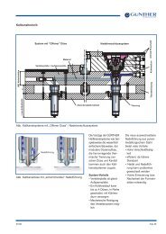
Heater connections, straight / frame version<br />
Structural notices for air circulation and high-temperature applications<br />
Screw fastenings for _MT/_NT/_TT nozzles<br />
Manifold power calculation, correlation of cables<br />
Construction of the hot-runner system<br />
Complete mold halves “hot halves”<br />
Service program<br />
CADHOC System-Designer<br />
Delta tool calculation program, application database<br />
Online-catalog, MoldCae/Moldflow analyse<br />
Seminars for users and designers<br />
Page<br />
1.4. 2 + 3<br />
1.4. 4 + 5<br />
1.4. 6<br />
1.4. 7<br />
1.4. 10<br />
1.4. 10<br />
1.4. 11<br />
1.4. 11<br />
1.4. 12<br />
1.4. 20<br />
1.4. 20<br />
1.4. 21<br />
1.4. 21<br />
1.4. 30<br />
1.4. 31<br />
1.4. 32<br />
1.4. 33 + 34<br />
1.4. 35<br />
1.4. 35<br />
1.4. 36<br />
1.4. 37<br />
1.4. 40<br />
1.4. 41<br />
1.4. 42<br />
1.4. 43<br />
1.4. 50<br />
1.4. 51<br />
1.4. 52<br />
1.4. 53<br />
1.4. 54<br />
1.4. 55<br />
1.4. 56<br />
1.4. 60<br />
1.4. 61<br />
1.4. 62<br />
1.4. 63<br />
www.guenther-hotrunner.com<br />
4/11 Subject to technical changes<br />
1.4. 1
iT<br />
<strong>Hot</strong> runner nozzle<br />
Fig. Disassembly of a multi-tip nozzle<br />
Reference notes on disassembly<br />
of a multi-tip nozzle<br />
To avoid damaging nozzle tips, we<br />
suggest a mechanical construction<br />
which imposes a change in the way<br />
the nozzle is disassembled :<br />
1. Loosen the wedge and the counter-pressure<br />
insert.<br />
2. Push out the divided form inserts<br />
to the right and left over the nozzle<br />
tips to their limits.<br />
3. Now pull out the form inserts<br />
downwards in the direction of the<br />
cavity.<br />
4. Loosen the screw fastening for<br />
the suppressor and remove it<br />
5. Now the nozzle can be taken upwards.<br />
What should be observed in the<br />
construction phase:<br />
1 To prevent jetting, inject against a<br />
core, for example.<br />
2. The shear edge must amount to at<br />
least the injection gate diameter<br />
+ 0.2 mm (see drawing).<br />
3. There should not be any draft<br />
angle in the injection gate area<br />
(see drawing).<br />
1.4. 37<br />
www.guenther-hotrunner.com<br />
Subject to technical changes 4/11
Materials<br />
iT<br />
Reference values for maximum nozzle throughput per second<br />
Nozzle length: 50/ 100 mm<br />
3<br />
Throughput in cm /s<br />
Low viscosity material: e. g. PA, PS, PP<br />
120<br />
100<br />
80<br />
60<br />
40<br />
20<br />
0<br />
ø 4 mm<br />
Nozzle length 50 mm<br />
Nozzle length 100 mm<br />
ø 5 mm<br />
ø 6 mm<br />
The specified throughputs are reference<br />
values. Considerable deviations<br />
for specific materials cannot<br />
be excluded. We will be glad to<br />
assist you with the selection of<br />
channel Ø.<br />
Additional applications which have<br />
already been implemented can be<br />
found in the application database on<br />
our website<br />
www.guenther-hotrunner.com<br />
menu item: “Application Database”.<br />
Medium viscosity material: e. g. ABS, PPO<br />
120<br />
3<br />
Throughput in cm /s<br />
100<br />
80<br />
60<br />
40<br />
20<br />
0<br />
ø 4 mm<br />
Nozzle length 50 mm<br />
Nozzle length 100 mm<br />
ø 5 mm<br />
ø 6 mm<br />
High viscosity material: e. g. Polycarbonate, Bayblend, Polysulfon<br />
30<br />
3<br />
Throughput in cm /s<br />
25<br />
20<br />
15<br />
10<br />
5<br />
0<br />
ø 4 mm<br />
Nozzle length 50 mm<br />
Nozzle length 100 mm<br />
ø 5 mm<br />
ø 6 mm<br />
www.guenther-hotrunner.com<br />
4/11 Subject to technical changes<br />
1.4. 2
iT<br />
Materials<br />
The specified throughputs are<br />
reference values. Considerable<br />
deviations for specific materials<br />
cannot be excluded. We will be glad<br />
to assist you with the selection of<br />
channel Ø.<br />
Additional applications which have<br />
already been implemented can be<br />
found in the application database on<br />
our website<br />
www.guenther-hotrunner.com<br />
menu item: “Application Database”.<br />
Reference values for maximum nozzle throughput per second<br />
Nozzle lengths: 60/ 100 mm<br />
3<br />
Throughput in cm /s<br />
Low viscosity material: e. g. PA, PS, PP<br />
2500<br />
2250<br />
2000<br />
1750<br />
1500<br />
1250<br />
1000<br />
750<br />
500<br />
250<br />
0<br />
ø 8 mm ø 10 mm ø 12 mm<br />
Nozzle length 60 mm<br />
Nozzle length 100 mm<br />
Medium viscosity: e. g. ABS, PPO<br />
2500<br />
2000<br />
3<br />
Throughput in cm /s<br />
1500<br />
1000<br />
500<br />
0<br />
ø 8 mm ø 10 mm ø 12 mm<br />
Nozzle length 60 mm<br />
Nozzle length 100 mm<br />
3<br />
Throughput in cm /s<br />
High viscosity material: e. g. Polycarbonate, Bayblend,<br />
Polysulphone<br />
500<br />
450<br />
400<br />
350<br />
300<br />
250<br />
200<br />
150<br />
100<br />
50<br />
0<br />
ø 8 mm ø 10 mm ø 12 mm<br />
Nozzle length 60 mm<br />
Nozzle length 100 mm<br />
1.4. 3<br />
www.guenther-hotrunner.com<br />
Subject to technical changes 4/11
Materials<br />
iT<br />
Determining the gate diameter for standard materials depending on<br />
the part weight<br />
Gate diameter<br />
Please note:<br />
All specified reference values for the<br />
gate diameter apply only to hot<br />
runner nozzles with vertical gating.<br />
Gate diameter for fibre reinfor-ced<br />
materials<br />
The gate diameters for glass fibre<br />
reinforced materials or materials<br />
containing additives (flame retardants,<br />
heat stabilisers) 0.2 to 0.3 mm<br />
larger.<br />
The same applies to multi-tip nozzles.<br />
Please contact us for all other types<br />
of gating.<br />
Article weight<br />
Material: PC + ABS<br />
Material: PE<br />
Ø D mm<br />
2.8<br />
2.4<br />
2.0<br />
1.6<br />
1.2<br />
0.8<br />
0.4<br />
0.1 1 3 5 8 10 100 1000<br />
Article weight g<br />
Ø D mm<br />
2.8<br />
2.4<br />
2.0<br />
1.6<br />
1.2<br />
0.8<br />
0.4<br />
0.1 1 3 5 8 10 100 1000<br />
Article weight g<br />
Material: PMMA<br />
Material: POM, PA 6, ABS<br />
Ø D mm<br />
2.8<br />
2.4<br />
2.0<br />
1.6<br />
1.2<br />
0.8<br />
0.4<br />
0.1 1 3 5 8 10 100 1000<br />
Article weight<br />
g<br />
Ø D mm<br />
2.8<br />
2.4<br />
2.0<br />
1.6<br />
1.2<br />
0.8<br />
0.4<br />
0.1 1 3 5 8 10 100 1000<br />
Article weight g<br />
www.guenther-hotrunner.com<br />
4/11 Subject to technical changes<br />
1.4. 4
iT<br />
Materials<br />
Material: PBT<br />
Material: PA 6.6 (glas filled + 0.3 mm)<br />
Ø D mm<br />
2.8<br />
2.4<br />
2.0<br />
1.6<br />
1.2<br />
0.8<br />
0.4<br />
0.1 1 3 5 8 10 100 1000<br />
Article weight g<br />
Ø D mm<br />
2.8<br />
2.4<br />
2.0<br />
1.6<br />
1.2<br />
0.8<br />
0.4<br />
0.1 1 3 5 8 10 100 1000<br />
Article weight g<br />
Material: PS<br />
Material: TPU, TPE<br />
Ø D mm<br />
2.8<br />
2.4<br />
2.0<br />
1.6<br />
1.2<br />
0.8<br />
0.4<br />
0.1 1 3 5 8 10 100 1000<br />
Article weight g<br />
Ø D mm<br />
2.8<br />
2.4<br />
2.0<br />
1.6<br />
1.2<br />
0.8<br />
0.4<br />
0.1 1 3 5 8 10 100 1000<br />
Article weight g<br />
Material: PPO<br />
Material: SB, SAN<br />
Ø D mm<br />
2.8<br />
2.4<br />
2.0<br />
1.6<br />
1.2<br />
0.8<br />
0.4<br />
0.1 1 3 5 8 10 100 1000<br />
Article weight g<br />
Ø D mm<br />
2.8<br />
2.4<br />
2.0<br />
1.6<br />
1.2<br />
0.8<br />
0.4<br />
0.1 1 3 5 8 10 100 1000<br />
Article weight g<br />
Material: PSU, PC<br />
Material: PP<br />
Ø D mm<br />
2.8<br />
2.4<br />
2.0<br />
1.6<br />
1.2<br />
0.8<br />
0.4<br />
0.1 1 3 5 8 10 100 1000<br />
Article weight g<br />
Ø D mm<br />
2.8<br />
2.4<br />
2.0<br />
1.6<br />
1.2<br />
0.8<br />
0.4<br />
0.1 1 3 5 8 10 100 1000<br />
Article weight g<br />
Material: LCP<br />
Ø D mm<br />
2.8<br />
2.4<br />
2.0<br />
1.6<br />
1.2<br />
0.8<br />
0.4<br />
0.1 0,5 1 3 5 8 10 100 1000<br />
Article weight g<br />
1.4. 5<br />
www.guenther-hotrunner.com<br />
Subject to technical changes 4/11
Materials<br />
iT<br />
Material<br />
Recommended<br />
processing temperature (°C)<br />
Recommended<br />
WZ-temperatur (°C)<br />
Processing window for common<br />
plastics<br />
PP<br />
PE<br />
PS<br />
ABS<br />
SAN<br />
PA 6<br />
PA 6.6<br />
POM<br />
PC<br />
PMMA<br />
PBT<br />
ABS / PC<br />
LCP*<br />
PPS<br />
PEEK<br />
220 - 280<br />
220 - 280<br />
220 - 280<br />
220 - 250<br />
220 - 250<br />
240 - 250<br />
270 - 290<br />
205 - 215<br />
280 - 310<br />
220 - 250<br />
245 - 270<br />
260 - 270<br />
300 - 345<br />
310 - 340<br />
360 - 400<br />
20 - 60<br />
20 - 60<br />
20 - 70<br />
40 - 80<br />
40 - 80<br />
40 - 60<br />
40 - 80<br />
60 - 120<br />
80 - 120<br />
40 - 90<br />
60 - 80<br />
70 - 100<br />
80 - 120<br />
140 - 145<br />
140 - 180<br />
* depending on polymer-type<br />
Price / performance<br />
The performance pyramid<br />
High temperature resistant<br />
plastics<br />
(HDT > 150°C)<br />
Technical plastics<br />
(HDT = 100 - 150°C)<br />
COC<br />
PAR<br />
PES<br />
PC<br />
PPO<br />
PI<br />
PEI<br />
PSU<br />
PEK<br />
FP<br />
LCP PAI<br />
PPS<br />
PA 46 PPA<br />
PET<br />
PBT PA6.6<br />
POM<br />
LFT<br />
High temperature resistant<br />
plastics<br />
High temperature resistant plastics<br />
with processing temperatures<br />
>300°C:<br />
• Liquid Crystal Polymer (LCP)<br />
• Polyphenylene sulphide (PPS)<br />
• Polyetherketone /<br />
Polyetheretherketone<br />
(PEK/ PEEK)<br />
• Polysulphone (PSU)<br />
• Polyether-Imide (PEI) etc.<br />
Standardplastics<br />
SAN ABS PMMA PP<br />
PS<br />
PVC<br />
SAN<br />
PE-LD<br />
amorphous<br />
PE-HD<br />
semy-crystalline<br />
www.guenther-hotrunner.com<br />
4/11 Subject to technical changes<br />
1.4. 6
iT<br />
Materials<br />
ØD1<br />
ØD2<br />
Fig. Gate design A and hot-runner nozzle with<br />
nozzle piece version C<br />
Polyacetal (POM) and Thermo Plastic Elastomers (TPE)<br />
Gate design A<br />
When processing polyacetal (POM) and thermoplastic<br />
elastomers (TPE) with a hot runner nozzle with nozzle<br />
piece, version C and the gate design A, a good injection<br />
gate quality should be attained. <strong>Hot</strong> runner nozzles with<br />
nozzle piece, version C can be used for injection onto an<br />
intermediate gate and also for direct gating. In direct<br />
gating a higher residual sprue must be expected than<br />
when a nozzle with tip is used. The gate design A must<br />
be used for nozzles with tip and for open nozzles. It must<br />
be taken into account here that the injection gate<br />
diameter in gate bushing "D1" must be smaller than the<br />
diameter in the nozzle piece "D2”<br />
(D1 < D2). When a nozzle piece, version C is used, the<br />
shear in the melt in the area of the injection gate is lower<br />
than when a nozzle with tip is used.<br />
Shear-sensitive materials<br />
Gate design C<br />
Single nozzles are mostly used when processing shearsensitive<br />
materials through an intermediate gate. The<br />
gate design C is exclusively used for open nozzles with a<br />
nozzle piece, version A.<br />
ØD2<br />
It must be taken into account here that the injection gate<br />
diameter in the "D1" gate bushing must be larger than<br />
the diameter of the nozzle piece "D2" (D1 > D2).<br />
ØD1<br />
Fig. Gate design version C and hot-runner nozzle with<br />
nozzle piece version A<br />
55°<br />
2,5...3,5<br />
Parts made of Polypropylene (PP)<br />
<strong>Hot</strong> runner nozzles with modified tip geometry should be<br />
used to process polypropylene. At a height of 2.5 to 3.5<br />
mm (depending on the nozzle type) the tip angle is<br />
reduced from 55° to 40°.<br />
This modified geometry must be ordered separately.<br />
40°<br />
Fig.Tip geometry for polypropylene<br />
1.4. 7<br />
www.guenther-hotrunner.com<br />
Subject to technical changes 4/11
Gating<br />
iT<br />
80°<br />
6,3<br />
Gating<br />
The hot runner nozzle’s function is<br />
essentially influenced by gate size<br />
diameter “D”.<br />
d<br />
H<br />
An enlargement of gate size must<br />
be done at an 80° angle. The edge<br />
must be sharp to achieve clean<br />
separation.<br />
Fig. Gate geometry<br />
ØD<br />
sharp-edged<br />
Note:<br />
The most frequented faults on<br />
commissioning a mould are due to<br />
the incorrect design of the gate<br />
geometry.<br />
H [mm]<br />
4,0<br />
Inspecting the gate<br />
The correct position of the 80° angle<br />
is inspected with a measuring ball.<br />
d = 4 mm<br />
3,5<br />
d = 3 mm<br />
3,0<br />
2,5<br />
2,0<br />
1,0 1,5 2,0 2,5 3,0<br />
Ø D [mm]<br />
Fig. Inspecting the gate<br />
Reworking the gate<br />
It is wrong to rework the gate by<br />
boring it out. The flow gap will not be<br />
substatially enlarged but the tear-off<br />
height on the part will become larger.<br />
Wrong<br />
Fig. Reworking the gate<br />
www.guenther-hotrunner.com<br />
4/11 Subject to technical changes<br />
1.4. 10
iT<br />
Gating<br />
L + L + 0.02<br />
Reworking the gate<br />
With gate diameters smaller than<br />
ØD = 1.2 mm, the nozzle must<br />
beinstalled further back.<br />
You will find a Delta Tool calculation<br />
program on our homepage at<br />
www.guenther-hotrunner.com<br />
available for download free of charge.<br />
ØD<br />
Fig. Nozzle installed in a retracted position<br />
Within the framework of permissible processing<br />
parameters, the smallest possible gate diameter means:<br />
small gate diameter<br />
tool temperature<br />
processing temperature<br />
Reducing the gate diameter<br />
The gate diameter cannot be<br />
arbitrarily reduced. The smallest<br />
permissible diameter is dependent<br />
on the material used.<br />
Furthermore, the gate size is also influenced<br />
by the mold temperature<br />
and processing temperature.<br />
Fig. Reducing the gate diameter<br />
This is the point at<br />
which the material<br />
solidifies at last.<br />
Vacuoles under the gate<br />
Direct gating with a hot runner system<br />
can produce vacuoles under the<br />
gate.<br />
Remedy:<br />
Longer holding pressure time to<br />
compensate for shrinkage.<br />
Fig. Vacuoles under the gate<br />
Gate diameter for fibre reinforced<br />
materials<br />
The gate diameters for glass fibre<br />
reinforced materials or materials<br />
containing additives (flame retardants,<br />
heat stabilisers) 0.2 to 0.3 mm<br />
larger. The same applies to multi-tip<br />
nozzles.<br />
1.4. 11<br />
www.guenther-hotrunner.com<br />
Subject to technical changes 4/11
Gating<br />
iT<br />
0.5<br />
At 250°C the hot runner nozzle extends 0.5 mm into<br />
the part if the nozzle is installed to the nominal<br />
length.<br />
Fig. <strong>Hot</strong> runner nozzle installed correctly<br />
Potential error sources<br />
Problem:<br />
- Higher vestige<br />
- No flow gap despite a larger gate<br />
Fig. Cylindrical part at the gate<br />
Problem:<br />
- The expanded nozzle closes the gate.<br />
Fig. Gate
Injection<br />
iT<br />
ØD<br />
L<br />
Correct injection into an intermediate<br />
gate<br />
In order to obtain defined separation,<br />
the aperture in the face surface of the<br />
intermediate gate Ød should be<br />
larger than ØD. This is particularly<br />
true for reinforced thermoplastics<br />
(engineering plastics).<br />
If possible, employ a catch pit in the<br />
intermediate gate.<br />
Ød<br />
˜<br />
1 mm > ØD<br />
catch pits<br />
Fig. Injection into an intermediate gate<br />
advantageous<br />
Gating into an angled surface<br />
Direct gating into an angled surface<br />
never results in an optimal gate point<br />
with a small vestige. We therefore<br />
recommend gating into a surface at<br />
right angle to the nozzle axis.<br />
advantageous<br />
disadvantageous<br />
Fig. Gating into an angled surface<br />
www.guenther-hotrunner.com<br />
4/11 Subject to technical changes<br />
1.4. 20
iT<br />
Gating<br />
Tempering<br />
Reserve gating into a high gloss<br />
facing surface<br />
Sufficient cooling is recommended<br />
for the gate area, next to the nozzle<br />
and on the ejector side to dissipate<br />
the heat additionally induced by<br />
shear.<br />
Insert<br />
The cooling circuit control must be<br />
separated from the other tempering<br />
circuits.<br />
Tempering<br />
Fig. Reserve gating into a high gloss facing surface<br />
Film hinge<br />
Articles with a film hinge<br />
When gating a part with a film hinge,<br />
the gating point must be located<br />
away from the surface center<br />
opposite to the film hinge. The flow<br />
front may not come to a standstill<br />
during the filling process. The film<br />
hinge must be filled last.<br />
Fig. Parts with a film hinge<br />
1.4. 21<br />
www.guenther-hotrunner.com<br />
Subject to technical changes 4/11
<strong>Hot</strong> runner nozzle<br />
iT<br />
Z ±0.02<br />
Fig. Nozzle length at room temperature<br />
Nozzle length at room temperature<br />
Our nozzle length is made to the size<br />
that already provides for ist length<br />
change when heated to 250° C. The<br />
nozzle tip will then extend by 0.5 mm<br />
into the cavity contour. Dimension Z<br />
(as measured at room temperature)<br />
is equal to:<br />
Z = L + 0.5 - l (250°)<br />
l consequently depending on L<br />
itself.<br />
l is the temperature dependent<br />
longitudinal expansion of the<br />
hot runner nozzle.<br />
Standard<br />
90°<br />
Increased angle<br />
120°<br />
Attention!<br />
Provide for adequate<br />
wall thickness.<br />
Insulation gap<br />
Insulation gap<br />
Modification of fore chamber<br />
geometry<br />
Fore chamber geometry can be<br />
modified for special applications or<br />
difficult-to-process materials (e. g.<br />
V0-adjusted materials).<br />
To avoid mistakes, we recommend<br />
that you consult with our<br />
application engineers.<br />
Enlarging the angle to 120°<br />
The standard angle of 90° in the forechamber<br />
can be widened to 120°.<br />
This will enlarge the insulation gap<br />
between the hot runner nozzle and<br />
the mold. The nozzle can be operated<br />
at a lower temperature so that<br />
thermally sensitive material will not<br />
be damaged.<br />
Fig. Modification of forechamber geometry<br />
Using a titanium sleeve over the<br />
nozzle shaft in combination with<br />
an angle of 120 °.<br />
The insulation gap between the hot<br />
runner nozzle and the mold also<br />
becomes larger and the heat transfer<br />
to the cavity plate is reduced.<br />
Titanium sleeve<br />
Insulation gap<br />
120°<br />
Fig. Employment from a titanium sleeve<br />
www.guenther-hotrunner.com<br />
4/11 Subject to technical changes<br />
1.4. 30
iT<br />
<strong>Hot</strong> runner nozzle<br />
Reference values for screw sizes<br />
The centering flange and screws of<br />
single nozzles must absorb the<br />
emerging lift forces.<br />
Screws and centering flange are to<br />
be appropriately dimensioned and<br />
the pitch circle of the screws is to be<br />
kept as small as possible.<br />
Guide values for screw selection can<br />
taken from the table below. Tightening<br />
torque M A for producing the screw<br />
connection must afford sufficient<br />
pretensioning force F v so that the<br />
required initial tension is still present<br />
when under the influence of operating<br />
force (i. e. operating force of the hot<br />
runner nozzle).<br />
Pretensioning force F v should be a<br />
factor 2 to 4 greater than the anticipated<br />
operating force. Screws<br />
should be selected which are as<br />
long as possible.<br />
F = force<br />
p = injection<br />
pressure<br />
A = area of the<br />
nozzles shaft Ø<br />
Example:<br />
<strong>Hot</strong> runner nozzle: 5SET50 ( ØS = 22 mm)<br />
Injection pressure: 2000 bar (200 N/ mm 2)<br />
Number of screws: 4<br />
Reliability: 2-cavity<br />
Lift force on the hot runner nozzle:<br />
p<br />
D 2 ( mm) • π<br />
A =<br />
4<br />
A =<br />
F = p (N/ mm 2) • A ( mm 2)<br />
F = 200 N/ mm 2 • 380 mm2<br />
F<br />
= F A<br />
= 76000 N<br />
F = 76000<br />
ges<br />
22 mm 2 • π<br />
4<br />
A = 380 mm 2<br />
N<br />
Tightening torque for hot runner nozzles<br />
Pretension F v and tightening tor-que M A,<br />
for screws with head beaning surfaces per<br />
DIN EN ISO 4762 and 4014.<br />
Shaft screws ( µ ges. = 0.125)<br />
Pretension<br />
F v =<br />
F v =<br />
F v<br />
per screw:<br />
F ges ( N)<br />
Number of screws<br />
76000 N<br />
4<br />
F v = 38000 N per screw<br />
• Sicherheit<br />
• 2 (-fach)<br />
Chosen screws in consideration of 2-cavity<br />
reliability.<br />
4 x M10 - 12.9 je 45 kN per scres<br />
Thread<br />
designation<br />
Regular type<br />
screw threads<br />
M8<br />
M10<br />
M12<br />
M16<br />
M20<br />
M24<br />
Maximum pretension<br />
Property class<br />
10.9 12.9<br />
24<br />
38<br />
56<br />
105<br />
165<br />
235<br />
28<br />
45<br />
65<br />
122<br />
190<br />
275<br />
F V<br />
in kN<br />
Fine pitch<br />
thread<br />
M8x 1 26 31<br />
40<br />
M10x1,25 41 43<br />
77<br />
M12x1,5<br />
M16x1,5<br />
M20x1,5<br />
M24x2<br />
59<br />
114<br />
188<br />
265<br />
69<br />
134<br />
220<br />
310<br />
Maximum tightening torque M in Nm A<br />
Property class<br />
10.9 12.9<br />
37<br />
73<br />
125<br />
315<br />
615<br />
1050<br />
132<br />
340<br />
680<br />
1150<br />
43<br />
84<br />
148<br />
370<br />
700<br />
1250<br />
46<br />
90<br />
155<br />
390<br />
800<br />
1350<br />
1.4. 31<br />
www.guenther-hotrunner.com<br />
Subject to technical changes 4/11
<strong>Hot</strong> runner nozzle<br />
iT<br />
Power receptacle,<br />
alternating 230 V<br />
PE=earthed lead<br />
N = Neutral lead<br />
L = earthed lead<br />
Thermoplug CMLK<br />
Nozzle type:<br />
- 8-10SET/DET<br />
- 5-12NEST<br />
- 4-6SHT/DHT/NHT<br />
- 8-16SLT/DLT<br />
- 8-12NLT<br />
- 4-6SMT/DMT/NMT<br />
Red = plus<br />
Blue = minus<br />
Shield<br />
Fig. Designation / correlation of cables<br />
Power receptacle,<br />
alternating 230 V<br />
PE = earthed lead<br />
N = Neutral lead<br />
L = earthed lead<br />
Thermoplug CMLK<br />
Nozzle type:<br />
- 4-6STT/DTT/NTT<br />
- 4-6SMHT/DMHT<br />
Red = Plus<br />
Blue = Minus<br />
Shield<br />
Fig. Designation / correlation of cables<br />
www.guenther-hotrunner.com<br />
4/11 Subject to technical changes<br />
1.4. 32
iT<br />
<strong>Hot</strong> runner nozzle<br />
Thickfilm heaters for hot-runner<br />
nozzles<br />
BlueFlowGünther's new BlueFlow ®<br />
technology incorporates several<br />
advantages as compared to<br />
conventional heating methods: the<br />
heating elements are not only<br />
considerably smaller in diameter,<br />
they also allow a substantially better<br />
temperature distribution and<br />
accordingly, a quicker thermal<br />
response.<br />
Further outstanding features are<br />
their high electric strength and<br />
resistance to moisture. All in all,<br />
these four features are important<br />
steps taken towards a more spacesaving,<br />
precise and energy-efficient<br />
hot runner design and, therefore, a<br />
more effective injection molding<br />
process.<br />
<strong>Hot</strong> runner nozzle heater<br />
Heater are pressed into a brass<br />
body. The heater is fixed in place by<br />
the mechanical structure of the<br />
carrier body. The homogeneous<br />
brass body ensures optimal heat<br />
transfer from the heater to the<br />
material tube, showing a highly<br />
reproducible temperature pattern.<br />
Thermoplug CMLK<br />
Shield<br />
Blue = minus<br />
Red = plus<br />
Power receptacle,<br />
alternating 230 V<br />
Nozzle type:<br />
- 5SEF/DEF<br />
- SMF/DMF/NMF<br />
PE=earthed lead<br />
N = Neutral lead<br />
L = earthed lead<br />
Fig. Designation / correlation of cables<br />
22 mm<br />
18 mm<br />
Brass body with pressed-in heater<br />
BlueFlow® <strong>Hot</strong> runner nozzle<br />
Fig. <strong>Hot</strong> runner nozzle heater<br />
1.4. 33<br />
www.guenther-hotrunner.com<br />
Subject to technical changes 4/11
<strong>Hot</strong> runner nozzle<br />
iT<br />
High Quality. Blue. BlueFlow®<br />
The BlueFlow® hot runner nozzle<br />
sets new standards for quality and<br />
design of parts made of thermally<br />
sensitive plastics. This re-sults in<br />
better or even completely new<br />
application possibilities, depending<br />
on the application area in different<br />
sectors of industry.<br />
The thick film heater makes it<br />
possible to adjust the heating capacity<br />
to the exact power requirement<br />
in each single section over the<br />
entire nozzle length in order to reach<br />
a homogenous temperature.<br />
The plastic material in the material<br />
tube is hardly exposed to thermal<br />
stress, which means that the<br />
physical properties of the end<br />
product are obtainable even with<br />
thermally sensitive plastics and very<br />
small parts.<br />
FIg. Microfilter<br />
Example: Microfilter (automotive<br />
sector)<br />
Microfilter (outlet valve for an<br />
automotive application), injectionmolded<br />
in one process step from<br />
unreinforced PA66. This method has<br />
replaced the earlier procedure of<br />
insert-molding of an available metal<br />
or plastic mesh to obtain a ready-toinstall<br />
component. The resulting<br />
savings are dramatic: costs have<br />
decreased by 60-80%, depending<br />
on the product.<br />
Details: thread size 0.13;<br />
1848 gaps with 0.07 x 0.07 mm. 2<br />
Passage surface approx. 9 mm .<br />
Max. allowed flash is 4.5 µm.<br />
www.guenther-hotrunner.com<br />
4/11 Subject to technical changes<br />
1.4. 34
iT<br />
<strong>Hot</strong> runner nozzle<br />
<strong>Hot</strong>-runner nozzle OktaFlow ®<br />
for side multi-tip gatin under 90°<br />
without cold slug, in connection with a<br />
manifold or can be used as a single<br />
nozzle with heated adaptor.)<br />
Assembly of the star manifold<br />
Insert the star manifold and use 4<br />
hexagon socket head cap screws<br />
M3x12 to fasten it to the sleeve-type<br />
heating.<br />
Assembly of support<br />
Insert the support and mount the lid<br />
from the parting line. Note: the lid<br />
must be solidly bonded to the insert.<br />
Assembly of the hot-runner nozzle<br />
Push the hot-runner nozzle (MT) in<br />
from the nozzle side!<br />
<strong>Hot</strong>-runner nozzle PektaFlow®<br />
Number of tips: up to 24 tips, for side<br />
multi-tip gating under 90° without<br />
cold slug.<br />
Be used as a single nozzle with<br />
heated adaptor.<br />
<strong>Hot</strong>-runner nozzle Pekta Flow ® type PLT<br />
are designed for challenging applications<br />
e.g. in medical technology<br />
and packaging.<br />
• Direct injection onto the product<br />
• Divided inserts<br />
• Tips individually replaceable<br />
• Leading-edge area heated for<br />
optimum temperature<br />
development<br />
• Supported on floating bearings and<br />
therefore independent of the ther<br />
mal expansions<br />
1.4. 35<br />
www.guenther-hotrunner.com<br />
Subject to technical changes 4/11
<strong>Hot</strong> runner nozzle<br />
iT<br />
Without extended nozzle tip<br />
L +0.02<br />
With extended nozzle tip<br />
L1 +0.02<br />
L1 +0.02<br />
Extended nozzle tips in<br />
connection with the material<br />
It is often necessary to use several<br />
different nozzle lengths when gating<br />
a part. Extended nozzle tips allow<br />
sprueless molding of parts even in<br />
space constrained environments.<br />
Shimmed<br />
Inserted<br />
L1 +0.02<br />
L1 +0.02<br />
Fig. Use of nozzle with extended tip<br />
Side gating<br />
Under 90° without a ”cold slug” in<br />
combination with a manifold. Gating<br />
should always be against the core.<br />
Always specify the material to be<br />
processed and the part weight when<br />
making inqiries. Also specify whether<br />
a part is to be gated with several tips,<br />
or if several parts are to be molded.<br />
Note:<br />
Slide out the inserts only horizontally!<br />
Fig. Side gating under 90° without a “cold slug”<br />
www.guenther-hotrunner.com<br />
4/11 Subject to technical changes<br />
1.4. 36
Valve gate technology<br />
iT<br />
When the hot-runner system is being turned off, all<br />
control circuits can be turned off at the same time. To<br />
prevent the hot-runner system being damaged by the<br />
build-up of heat, let the mould cooling run on at about<br />
30°C for another 30 minutes approximately. The valve<br />
gate needles should be in the “closed” position here.<br />
Fig. Valve gate system<br />
Commissioning the valve gate system<br />
Before heating the nozzles and the manifold, switch on<br />
the mould temperature control.<br />
Heating the hot-runner system:<br />
- Heat the manifold with the controller unit's soft start<br />
function. With the softstart function the manifold is<br />
heated to about 100°C and held at this temperature<br />
for approximately 10 minutes.<br />
- The nozzles and manifold must be heated evenly.<br />
Heating the manifold to the target temperature can<br />
take up to 20 minutes.<br />
The needle mechanism may be put into operation when<br />
the hot-runner system reaches production temperature.<br />
The idle system must be held at production temperature<br />
for at least 10 minutes to ensure thermal stability.<br />
When putting into operation for the first time, several<br />
injections may be necessary in order to fill the hot runner<br />
completely with plastic. Until the parts are filled<br />
completely, the cavities must be checked after every<br />
cycle for parts that have not been filled completely.<br />
If the process is interrupted, the hot-runner temperature<br />
must be lowered (depending on the material and<br />
downtime by 100…150°C). The needles must be in the<br />
"closed" position. To prevent damage being caused to<br />
the gate bores / valve needles by cold material, the valve<br />
needles may not be actuated when the injection<br />
moulding machine is being set up or during injection out<br />
through the unit. If the melt is to be injected out through<br />
the open mould / hot runner, the needles must be opened<br />
during the injecting-through process and closed during<br />
the dosing phase.<br />
Before doing any disassembly, make sure the hot runner<br />
is switched off. To prevent damage to the needle guide /<br />
needle, the needles must be in the opened position.<br />
Before putting the system into operation again, make<br />
sure the needles are in the “closed” position again.<br />
Connection values<br />
Electric<br />
Voltage 230 V~<br />
System *<br />
max. permissible operating<br />
pressure in the hot-runner system 2000 bar<br />
*<br />
If special nozzles or other components with a pressure limit (less<br />
than 2000 bar) are fitted to systems or individual tools, this situation<br />
is documented in the height adjustment and on the type plate.<br />
Hydraulic<br />
Single valve- gate nozzle<br />
Lifting plate mechanism<br />
Sliding cam mechanism<br />
Pneumatic<br />
max. permissible operating<br />
pressure in the hot-runner system<br />
Single valve gate nozzle<br />
Single needle valve<br />
Lifting plate mechanism<br />
Sliding cam mechanism<br />
To attain the right needle speed (needle closing time 20-<br />
40 ms / 7-10 mm travel), the valve must be designed to be<br />
large enough for the actuation (hydraulic/pneumatic).<br />
The connection hoses too must be dimensioned to suit<br />
the flow volume.<br />
The distance between the pressure generation and the<br />
pressure consumption (mould) should be as small as<br />
possible.<br />
Note!<br />
The first filling of the hydraulic cylinders should be done<br />
at a low speed or the cylinders should be deaerated.<br />
40<br />
40-60<br />
40-60<br />
8<br />
mind. 8-10<br />
8<br />
8-10<br />
8-10<br />
bar<br />
bar<br />
bar<br />
bar<br />
bar<br />
bar<br />
bar<br />
bar<br />
www.guenther-hotrunner.com<br />
4/11 Subject to technical changes<br />
1.4. 40
iT<br />
Valve gate technology<br />
Insulation ring<br />
Steel piston ring, large<br />
Marking XXX<br />
Steel piston ring, small<br />
Power connection<br />
Marking XXX<br />
Fixed thermocouple<br />
connection<br />
Power connection<br />
Fixed thermocouple<br />
Scew M10x1<br />
Needle closing<br />
Needle opening<br />
Fig. Single valve-gate nozzle 12NEST<br />
There are three 0.1-mm shims over / under the needle<br />
head.<br />
Caution<br />
When assembling / dismantling the needle holder (A/F<br />
10), care must be taken not to deform the steel piston<br />
rings. Use the flat of the piston! It is essential to put the<br />
metal O ring back in after replacing the disk package. The<br />
piston and/or the steel piston rings must be greased<br />
again before assembly (<strong>GÜNTHER</strong> recommends Klüber<br />
paste UH 196-402 [NSF registered]).<br />
Furthermore, it is essential to ensure that the steel piston<br />
rings have been inserted correctly. The rings have a<br />
marking (XXX) on the face surface, indicating the side<br />
that must point towards the pressurised side.<br />
Installation of the complete nozzle<br />
The cables for activating the needles are located at the<br />
bottom of the nozzle. Accordingly the centring ring can be<br />
produced as a “bell”. This measure makes it possible to<br />
reduce the height of the mould.<br />
Screw centring with at least 4x M12 (10.9) screws, with<br />
due consideration to lift forces. For an optimum thermal<br />
separation between the nozzle and the mould, use the<br />
(blue) insulation ring.<br />
Caution: Grind in the K dimension in compliance with the<br />
data in the chapter. 2.3 yellow page.<br />
Inlet/ outlet pipes for activating the needle<br />
It is preferable to use channels with diameters of 6 mm<br />
and a minimum length of 200 mm. The inlet and outlet<br />
lines must be placed in the cooled mould plate in order to<br />
prevent the medium overheating. If the mould<br />
temperatures exceed the thermal stress capability of the<br />
pneumatic valves, a separately cooled manifold must be<br />
installed. The mechanics of the needle drive and the<br />
valve gate nozzle are absolutely capable of withstanding<br />
high temperatures.<br />
Note on guarantee<br />
<strong>GÜNTHER</strong> guarantees nozzle type NEST only if they<br />
have been fitted or serviced on <strong>GÜNTHER</strong> premises or<br />
by a <strong>GÜNTHER</strong> specialist. <strong>GÜNTHER</strong> will not provide<br />
any guarantee for damage caused by the incorrect fitting<br />
of the steel piston ring operated nozzle type NEST by<br />
the pur-chaser, its representatives or contractors.<br />
The same applies to inappropriate or neglected<br />
maintenance.<br />
1.4. 41<br />
www.guenther-hotrunner.com<br />
Subject to technical changes 4/11
Valve gate technology<br />
iT<br />
Electromagnet ME 10/UV75<br />
The ME 10 bistable heavy-duty lifting magnet serves<br />
to actuate the valve gate needles in valve gate<br />
systems.<br />
Excellent for fully electric injection moulding machines<br />
and for clean room use.<br />
Single needle valve ENV<br />
Needle actuation in single and multiple systems.<br />
Sequential opening and closing of the needles.<br />
Special holes in the mould clamping plate allow the<br />
down-stroke depth of the valve gate to be adjusted<br />
individually from the outside.<br />
Maximum working temperature is 100° C.<br />
Pay attention to the balancing of the oil feed and oil<br />
outlet ducts as well as of the air feed and air outlet ducts.<br />
Note on guarantee<br />
<strong>GÜNTHER</strong> guarantees single needle valves only if they have been fitted or serviced on <strong>GÜNTHER</strong> premises or by a<br />
<strong>GÜNTHER</strong> specialist. <strong>GÜNTHER</strong> will not provide any guarantee for damage caused by the incorrect fitting of the O-rings<br />
in hydraulically/pneumatically operated single needle valves by the purchaser, its representatives or contractors.<br />
The same applies to inappropriate or neglected maintenance.<br />
Note: See operating instructions for details.<br />
Lifting plate mechanism ANEH<br />
The lifting mechanism is recommendable for a precisely<br />
simultaneous opening and closing of all needles.<br />
Special holes in the mould clamping plate allow the<br />
down-stroke depth of the valve needles to be adjusted<br />
individually from the outside.<br />
The maximum working temperature is 100° C.<br />
Sliding cam mechanism ANES<br />
For narrow cavity spacing a sliding cam mechanism is the<br />
preferred drive.<br />
Exact opening and closing of all needles.<br />
Special holes in the mould clamping plate allow the<br />
down-stroke depth of the valve gate to be adjusted<br />
individually from the outside.<br />
Maximum working temperature is 100° C.<br />
www.guenther-hotrunner.com<br />
4/11 Subject to technical changes<br />
1.4. 42
iT<br />
Valve gate technology<br />
Notes on valve needles<br />
The needle length is dependent on the nozzle length,<br />
type of actuation and manifold structure. The needles<br />
have a basic hardness of 64 HRC (HSS steel) and are<br />
coated. The needles are fitted with a cylindrical seal<br />
towards the cavity and are adjustable.<br />
The 2 mm Ø needle design for nozzles with material<br />
tube-Ø 4-6 mm, threads M6x 0,5<br />
gate-Ø: 0,8 mm, 1,0 m, 1,2 mm, 1,4 mm, (1,6 mm).<br />
The 3 mm Ø needle design for nozzles with material<br />
tube- Ø 8 mm, threads M8 x 0,5<br />
gate Ø: 2,0 mm, 2,5 mm.<br />
The 5 mm Ø needle design for nozzles with material<br />
tube- Ø 10-12 mm, threads M10 x 0,75<br />
gate- Ø: 3,0 mm, 4,0 mm.<br />
Tools to disassembling the needle guide (piece of PM),<br />
see chapter 7.<br />
Maintenance<br />
Sliding cam mechanismus -ANES-<br />
When fitting the sliding cam mechanism, use a hightemperature<br />
long-life grease to lubricate the movable<br />
parts. This allows the sliding cam mechanism to work<br />
without any problems even at higher temperatures over a<br />
long period of time. Make sure the mould temperature<br />
does not exceed 100° C in the area of the frame plate/<br />
clamping plate.<br />
During maintenance the sliding cam mechanism must be<br />
checked for dirt and wear. Melts that have exuded from<br />
the manifold sealing because of the stroke movement of<br />
the needles must be removed. In older hot-runner<br />
systems the sliding cam mechanism can be relubricated<br />
through the ball impact holes (DIN 3410 Form F); in new<br />
systems the sliding cam mechanism can be relubricated<br />
without disassembly.<br />
Thread tightening torque for needle adjustment<br />
Needle Ø Thread Tightening torque<br />
M A [Nm]<br />
Ø 2 mm M6 x 0,50 15<br />
Ø 3 mm M8 x 0,50 30<br />
Ø 5 mm M10 x 0,75 45<br />
Type NEP<br />
Type NHP<br />
Fig.<br />
Sliding cam mechanism<br />
with externally accessible<br />
grease fittings<br />
Fig.<br />
Ball impact holes<br />
To ensure optimal greasing performance also at higher<br />
temperatures, avoid using different greases. We<br />
recommend the lubricating grease from Klueber<br />
Barrierta L55/2 high temperature long-life grease. The<br />
lubricating grease can be purchased either directly from<br />
the manufacturer or from us. Safety data sheets can be<br />
called up at www.klueber.com.<br />
Introduction: Lubrication after 150.000 shots or<br />
1x weekly.<br />
Maintainance work (cleaning) must be done on the<br />
needle-driving mechanisms every 400.000 shots!<br />
This frequency depends greatly on the material to be<br />
processed or the application. If a thermoplastic<br />
elastomer (TPE) is being processed, it may be necessary<br />
to do maintenance work on the sliding cam after just<br />
approximately 200.000 shots. This also concerns<br />
polymers, in which the viscosity is greatly reduced by the<br />
shearing.<br />
1.4. 43<br />
www.guenther-hotrunner.com<br />
Subject to technical changes 4/11
<strong>Hot</strong> runner systems / manifolds<br />
iT<br />
V2<br />
NEW: Sign up at www.guenther-hotrunner.com to start<br />
configuring your individual hot runner system with<br />
CADHOC V2 System Designer.<br />
You will save time and cut costs by having detailed<br />
information at an early phase of your project.<br />
NEW: <strong>Hot</strong> half on the basis of the<br />
• 8-cavity H manifold“<br />
• 2-cavity straight manifold" and<br />
• 4-cavity cross manifold"<br />
For mould size up 196x296 mm to 796x996 mm<br />
(depending on the manifold size and manifold design).<br />
<strong>Hot</strong> half as 2-plate system, incl. guide elements, cable<br />
duct, cooling etc.<br />
NEW: <strong>Hot</strong> half as 2-plate system, incl. guide elements,<br />
cable duct, cooling etc. All system nozzles with a tip<br />
and an open nozzle piece can be used (Catalogue<br />
Chapter 2.1).<br />
NEW: Valve-gate systems with<br />
single needle valves for “individual” types of manifold.<br />
• Straight manifold 1-cavity, 2-cavity und 4-cavity<br />
• H manifold 4-cavity and 8-cavity,<br />
• T manifold 2-cavity and<br />
• Cross manifold 4-cavity<br />
with nozzles from our valve gate portfolio.<br />
Catalogue Chapter 2.3).<br />
www.guenther-hotrunner.com<br />
4/11 Subject to technical changes<br />
1.4. 50
iT<br />
<strong>Hot</strong> runner systems / manifolds<br />
View straight/frame version<br />
Position of power connections<br />
Note:<br />
• Nozzles should always be surrounded by heater loops.<br />
• Heater lines should be routed mirror-inverted (cold<br />
ends of the tube heaters compensate for one another).<br />
• When possible, reserve an area for connectors where<br />
no material-carrying bore holes are located.<br />
• For high temperature applications > 320°C external<br />
connectors are appropriate.<br />
Fig. View: straight version<br />
Fig. Internal heater<br />
connections<br />
Fig. External heater<br />
connections<br />
Frame plate / rail<br />
Edges absolutely burr-free<br />
Supporting plate /<br />
cavity plate<br />
Fig. View: f rame version<br />
Fig. Cable channel<br />
Not recommended<br />
Recommended<br />
Fig. Cable channel<br />
Fig. Cable channel<br />
1.4. 51<br />
www.guenther-hotrunner.com<br />
Subject to technical changes 4/11
<strong>Hot</strong> runner systems / manifolds<br />
iT<br />
Air circulation<br />
Attachment<br />
:<br />
housing<br />
Insulating plate<br />
Clamping plate<br />
Fig. Optimal air circulation<br />
Distance bolts<br />
Manifold<br />
Frame structure<br />
Fig. Cross section of a mold - optimal air circulation<br />
High temperature application<br />
Special hot runner design is necessary<br />
for plastics with processing<br />
temperatures over 320°C. This includes<br />
full insulation, external heater<br />
connectors and high tempe-rature<br />
resistant thermo-couples.<br />
In the nozzle area it requires a fixed,<br />
high temperature resistant thermocouple<br />
connection, a hard metal tip<br />
(for reinforced polymers) as well as a<br />
high temperature pro-tective sleeve<br />
for cables.<br />
Fig. Manifold for high temperature application<br />
www.guenther-hotrunner.com<br />
4/11 Subject to technical changes<br />
1.4. 52
iT<br />
<strong>Hot</strong> runner systems / manifolds<br />
Titanium washer<br />
Screw M6,<br />
M8, M10, (12.9)<br />
depending on<br />
manifold design<br />
Nozzle type<br />
_MT, _NT, _TT<br />
Fig. Manifold with _TT nozzle type, screwed to the<br />
parting line<br />
Fig. Screw fastenings for _MT/_NT/_TT nozzles<br />
Note:<br />
<strong>Hot</strong> runner nozzles of the _MT/_NT/_TT type are not<br />
screw-fastened to the manifold. The system is started<br />
with cold-state play. Please refer to the respective heat<br />
expansion table. In its cold state, the hot runner system<br />
has no positive seal between nozzles and manifold.<br />
Operating temperature must first be reached in order to<br />
seal the system. Please provide for adequate screw<br />
fixation of the clamping plate towards the cavity plate<br />
close enough to the manifold with at least 2x M10 per<br />
nozzle or, based on the length, 2x M10 per every 80 mm.<br />
We recommend connecting with screws of the 12.9<br />
property class.<br />
Advantages:<br />
• For high number of cavities and tight pitch spacing<br />
• Easy front mounting of the nozzles -<br />
the mold can remain on the machine for maintenance<br />
• Two fits provide a precise positioning to the pitch<br />
distance<br />
• Safety due to spatial and thermal separation of the<br />
connecting cable from the manifold<br />
• Protection against leakage by sealing the manifold<br />
from the cable channels om the cable channels<br />
Please use a pry bar or a nozzle extractor tool to<br />
professionally disassemble the nozzle from the gate<br />
bushing and/or cavity plate. See chapter 8.<br />
1.4. 53<br />
www.guenther-hotrunner.com<br />
Subject to technical changes 4/11
<strong>Hot</strong> runner systems / manifolds<br />
iT<br />
Manifold power calculation (230 V)<br />
Power Voltage Current Approximate resistance<br />
Watt Volt A<br />
values to be measured in<br />
Ohm [S]<br />
2300<br />
3680<br />
1500<br />
1400<br />
1100<br />
1000<br />
750<br />
500<br />
630<br />
500<br />
400<br />
250<br />
600 (max.)<br />
600 (max.)<br />
230<br />
230<br />
230<br />
230<br />
230<br />
230<br />
230<br />
230<br />
230<br />
230<br />
230<br />
230<br />
5<br />
24<br />
10<br />
16<br />
6.5<br />
6.1<br />
4.8<br />
4.4<br />
3.3<br />
2.8<br />
2.2<br />
1.8<br />
1.4<br />
1.1<br />
125 (max.)<br />
25 (max.)<br />
23.0<br />
14.375<br />
35.4<br />
37.7<br />
47.9<br />
52.3<br />
69.1<br />
82.1<br />
104.5<br />
127.8<br />
164.3<br />
209.1<br />
0.1 - 0.2<br />
0.2 - 0.4<br />
P = U • I<br />
R = U/I<br />
P = U 2 / R<br />
Example:<br />
P = (230 V) 2 / 23 Ohm<br />
P = 2300 W<br />
PE earthed lead<br />
Thermocouple<br />
cable<br />
Alternating current 230 V<br />
Red = plus<br />
Blue = minus<br />
Fig. Manifold - correlation of cables<br />
www.guenther-hotrunner.com<br />
4/11 Subject to technical changes<br />
1.4. 54
iT<br />
<strong>Hot</strong> runner systems / manifolds<br />
Assembly of the manifold<br />
1 2 3 4 5 6 7<br />
24<br />
8<br />
23<br />
22<br />
9<br />
10<br />
21<br />
11<br />
20<br />
19<br />
SNT SMT SHT STT<br />
12<br />
11 12 10 18<br />
17 16 15<br />
14 13<br />
Signs and symbols<br />
1<br />
PE-ground cabel connection, chap. 7<br />
9<br />
Manifold, chap. 4<br />
18<br />
Cylindrical pin to prevent twisting, chap. 4.1<br />
2<br />
Connection elements, chap. 6<br />
10<br />
Nozzle holding plate<br />
19<br />
Nozzle protrusion<br />
3<br />
4<br />
Bores in the clamping plate<br />
to fix the nozzle<br />
Surface mounted thermocouple,<br />
chap. 7<br />
11<br />
12<br />
13<br />
Cable channel<br />
Cavity plate<br />
<strong>Hot</strong> runner nozzles, chap. 2<br />
20<br />
21<br />
22<br />
Nozzle lengt, chap. 2<br />
Height of the nozzle head, chap. 2<br />
Manifold height<br />
5<br />
6<br />
7<br />
8<br />
Pressure pads, chap. 8<br />
Heat expansion gap dimension K,<br />
chap. 4.1<br />
Clamping plate<br />
Air gap at the top and bottom<br />
depending on tool position<br />
14<br />
15<br />
16<br />
17<br />
High temperature insulating plate, optional<br />
Gate bushing, chap. 2.2<br />
Support piece, chap. 8<br />
Tempering<br />
23<br />
24<br />
Installation height of the hotrunner<br />
Height of the pressure pad +<br />
Heat expansion gap dimension K<br />
1.4. 55<br />
www.guenther-hotrunner.com<br />
Subject to technical changes 4/11
<strong>Hot</strong> runner systems / manifolds<br />
iT<br />
Complete “<strong>Hot</strong> Halves”<br />
The hot half is delivered as a nozzleside<br />
mold half without cavity plates.<br />
The nozzle overhang over the supporting<br />
plate can be set individually.<br />
The height-matched hot runner is<br />
completely wired and functionally<br />
tested. This ready-to-install solution<br />
eliminates extensive design matching<br />
work and possible installation errors.<br />
Prior to delivery, hot halves are<br />
subjected to a functional test which is<br />
documented according to DIN EN<br />
ISO 9001:2000.<br />
Complete “<strong>Hot</strong> Halves” normally<br />
guarantee a smooth production<br />
start-up.<br />
Fig. Cross section of a mold<br />
Fig. Complete mold half “<strong>Hot</strong> Half”, valve gate system<br />
www.guenther-hotrunner.com<br />
4/11 Subject to technical changes<br />
1.4. 56
Service program<br />
iT<br />
Our comprehensive program of services<br />
is meant to provide you with the<br />
service you need, from consul-tation<br />
and layout for hot runner systems to<br />
practice-oriented seminars for users<br />
and designers.<br />
On the <strong>GÜNTHER</strong> website you will<br />
find many tools and programs to<br />
make your work easier.<br />
You can now configure your hot<br />
runner system individually via the<br />
<strong>GÜNTHER</strong> Internet platform. 3-D CAD<br />
data including negative volume and<br />
drawings are available for downloading<br />
for each hot runner system.<br />
To round this service off, price<br />
information (as a PDF file) is also<br />
provided.<br />
Once you have configured your<br />
individual hot runner system, you<br />
can select various data formats. The<br />
„CADHOC V2“ System Designer and<br />
the systems running in the background<br />
generate the required data.<br />
All files are then compressed and<br />
made available for downloading.<br />
You will be notified by e-mail a few<br />
minutes later.<br />
This e-mail will contain a link to the<br />
product data for the configured hot<br />
runner system.<br />
With its high functionality, the system<br />
is designed to suit the requirements<br />
of our customers, first of all<br />
designers of injection molds and<br />
sales personnel, to meet the desire<br />
for quicker availability of complete<br />
hot runner systems including negative<br />
volumes.<br />
Register once on our Internet platform „www.guenther-hotrunner.com“ and<br />
you can then start the CADHOC V2 system designer to configure your own<br />
individual hot-runner system.<br />
Advantages of the new CADHOC system-designers version 2:<br />
• optimised calculation of the nozzle size<br />
• extensive choice of types of plastic<br />
• two different methods of configuration<br />
- application-specific by entering processing parameters<br />
- direct configuration without entering processing parameters<br />
• shorter waiting periods during the configuration process<br />
www.guenther-hotrunner.com<br />
4/11 Subject to technical changes<br />
1.4. 60
iT<br />
Service program<br />
Reworking the 1.2 mm gate<br />
For gate diameters smaller than ØD<br />
= 1.2 mm, the nozzle must be<br />
installed further back from the gate.<br />
You will find a Delta Tool calculation<br />
program on our homepage at<br />
www.guenther-hotrunner.com under<br />
the menu item “Service” available<br />
for download free of charge.<br />
Fig. Delta Tool calculation program<br />
Application database<br />
The application database is a program<br />
for selecting from design proposals<br />
and machine parameter data.<br />
Following the entry of simple search<br />
criteria for hot runner requirements<br />
and material compa-tibility, the<br />
program makes available a selection<br />
of systems which have already been<br />
implemented along with their results.<br />
You can also enter your own applications<br />
directly into the data-base.<br />
The application will be reviewed and<br />
subsequently released under the<br />
menu item “Service”.<br />
The registration is free of charge.<br />
Fig. Application database with many applications already implemented<br />
1.4. 61<br />
www.guenther-hotrunner.com<br />
Subject to technical changes 4/11
Service program<br />
iT<br />
<strong>Download</strong> / catalog<br />
Under the menu item Catalog you<br />
will find all hot runner components<br />
with their relevant data available as a<br />
PDF file.<br />
The online catalog provides you with<br />
the newest version of the technical<br />
information.<br />
Here you can find <strong>GÜNTHER</strong> hot runner<br />
components with all the relevant information<br />
as a PDF file. Make use of extensive<br />
TM<br />
Acrobat Reader features, such as shortcuts,<br />
bookmarks and icons, for a comfortable and<br />
quick search for information!<br />
Fig. Online catalog<br />
Pressure drop /<br />
Filling analysis<br />
The melt channels are dimensioned<br />
by <strong>GÜNTHER</strong> on the basis of application-specific<br />
rheologic calculations,<br />
with pressure drop, shear<br />
and dwell time standing in the foreground.<br />
Our calculations can be expanded to<br />
include the filling analysis of plastic<br />
parts per Moldflow. This is particularly<br />
advisable when laying out family<br />
molds with different cavities. By<br />
performing this calcu-lation, we offer<br />
you support in determining an optimal<br />
gate position and demon-strate the<br />
flow front course for the ideal part<br />
filling along with anticipated air<br />
pockets and the course of the weld<br />
line.<br />
Fig. Filling analysis<br />
www.guenther-hotrunner.com<br />
4/11 Subject to technical changes<br />
1.4. 62
iT<br />
Service program<br />
Seminars for users and designers<br />
Topics, such as layout, smooth<br />
running operation and professional<br />
maintenance of <strong>GÜNTHER</strong> hot runner<br />
systems, are handled in a comprehensive<br />
manner.<br />
Additional services in our program<br />
include performing injection molding<br />
experiments in our in-house labora-<br />
tory as well as conducting external<br />
seminars. Please look for dates and<br />
locations on our website<br />
www.guenther-hotrunner.com under<br />
the menu item ”Seminars” or ask by<br />
phone at<br />
+49 (0) 64 51 - 5008-0.<br />
Fig. Seminars for designers and users<br />
Webinar, what's that?<br />
Webinar is an acronym formed from<br />
the words web (world wide web) and<br />
seminar.<br />
In short, it is a seminar held over the<br />
Internet.<br />
Advantages for you:<br />
•<br />
•<br />
concise and specific information<br />
no travelling and overnight accommodation<br />
expenses,<br />
no loss of working days!<br />
•<br />
See website<br />
www.guenther-hotrunner.com<br />
1.4. 63<br />
www.guenther-hotrunner.com<br />
Subject to technical changes 4/11